视觉定位软件VisionKit软件说明书
PTV Vision VISUM软件用户手册说明书
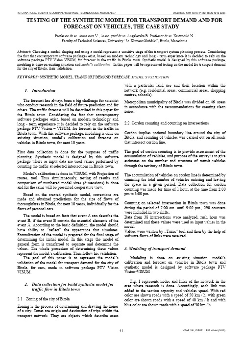
TESTING OF THE SYNTHETIC MODEL FOR TRANSPORT DEMAND AND FOR FORECAST ON VEHICLES, THE CASE STADYProfessor dr.sc. Atanasova V., Assoc. prof.dr.sc. Angelevska B. Professor dr.sc. Krstanoski N.Faculty of Technical Sciences, University “St. Kliment Ohridski”, Bitola, MacedoniaAbstract: Choosing a model, shaping and using a model represent a sensitive stage of the transport system planning process. Considering the fact that contemporary software packages exist, based on modern technology and long - term experience it is decided to rely on the software package PTV Vision VISUM, for forecast in the traffic in Bitola town. Synthetic model is designed by this software package, modeling is done on existing situation and model’s calibration. In this paper will be represented testing on the model for transport demand for the city of Bitola, their validation.KEYWORDS: SYNTHETIC MODEL, TRANSPORT DEMAND FORECAST, MODEL’S VALIDATION1.IntroductionThe forecast has always been a big challenge for scientist who conduct research in the field of future prediction and for others. The traffic forecast will be described in this paper for the Bitola town. Considering the fact that contemporary software packages exist, based on modern technology and long - term experience it is decided to rely on the software package PTV Vision – VISUM, for forecast in the traffic in Bitola town. With this software package, modeling is done on existing situation, model’s calibration and forecast on vehicles in Bitola town, for next 10 years.First data collection is done for the purposes of traffic planning. Synthetic model is designed by this software package where as input data are used values performed by counting the traffic at selected intersections in Bitola town.Model’s calibration is done in VISUM, with Projection of routes, tool. Thus simultaneously, testing of results and comparison of numbered model sizes (dimensions) is done and for the same will be presented cooperative view.Based on the created synthetic model, corrections are made and obtained predictions for the size of flows of thoroughfares in Bitola, for next 10 years, individually for the flows of personal cars.The model is based on facts that event A can describe the event B, if the event B contain the essential elements of the event A. According to the basic definition, the model should have ability to “reflect” the appearance that simulates. Formalization of the model is prepared for the final stage of determining the initial model. In this stage the model of general form is transferred to separate and determine the values. The whole procedure of determining these values represent the model’s ca libration. Then follow his validation.The goal of this paper is to represent the model’s validation of the model for transport demand for the city of Bitola, for cars, made in software package PTV Vision VISUM.2.Data collection for build synthetic model fortraffic flow in Bitola town2.1Zoning of the city of BitolaZoning is the process of determining and drawing the zones of a city. Zones are origin and destination of trips within the transport network. They are objects which describe areas with a particular land use and their location within the network (e.g. residential areas, commercial areas, shopping centres, schools).Metropolitan municipality of Bitola was divided on 46 areas in accordance with the recommendations for creating clean zones.2.2. Cordon counting and counting on intersectionsCordon implies notional boundary line around the city of Bitola, and counting of vehicles was carried out on all roads that intersect cordon line.The goal of cordon counting is to provide assessment of the accumulation of vehicles, and purpose of the survey is to give estimates on the number and structure of transit vehicles through the territory of Bitola town.The accumulation of vehicles on cordon line is determined by summing the total number of vehicles entering and leaving the space in a given period. Data collection for cordon counting was made for time of 1 hour, at the time from 2:00 pm to 3:00 pm.Counting on selected intersection in Bitola town was done during the period of 7:00 am. until 9:00 pm., 290 counters were included in two shifts.Data from 38 intersections were analyzed, rush hour was determined and these values were used as input values in the model.Values were written by ,,Turns” tool and then by the help of software flows of links were received.3. Modeling of transport demandModeling is done on existing situation, model’s calibration and forecast on vehicles in Bitola town and synthetic model is designed by software package PTV Vision-VISUMFig. 1 represents nodes and links of the network in the area where research is done. Accordingly, each link was added to the section capacity and vehicles speed. With red color are shown roads with a speed of 50 km / h, with green color are shown roads with a speed of 40 km / h and with blue color are shown roads with a speed of 30 km / h.Figure 1.Graphic display of roads network with different speed.First, in the proces of modeling in exsiting situation,for the purposes of the model is further zoning done. The main area include a different number of zones, so there are 46 zones. Fig. 2 represented the main zones (total 13) with blue, zones (total 40) with green and zones outside the city (total 6) with red color.Figure 2.Separation of the major areas in Zones.Second, we did choosing a model forecast of transport demand. The formulation of the model depends on the initial sizes and input variables that will encompass. The basic definition is that the model should have the ability to "reflect" the appearance that simulates.As input sizes in synthetic model are used the values of the counting of traffic at selected intersections, marked in red and shown on Fig. 3. Also are used data from cordon counting (cordon counting results are given in Section 2.2).Figure 3.Intersections counting in the area where research is done. Model’s calibration is done in VISUM, with Projection of routes, tool. The goal of calibration is bringing on counting and modals sizes together. Thus simultaneously, testing of results and comparison of numbered model sizes (dimensions) is done.Following comparative display of counting values (green color) and model’s sizes (in red) for personal cars.Figure 4.Counted values for cars on intersections, calculate in Visum, presented in sections.Figure 5.Modal values for cars on all network - existing situation.Figure 6.Counted and modal values for cars - existing situation.4. Forecast of traffic flow in Bitola townForecast is scientific prediction of some phenomena that are of great importance to human society. Based oncreatedsynthetic model, corrections are made and forecast on vehicles in Bitola town, for next 10 years.In the process of forecast the increase of 2% annually is taken into account. For the zones 26 and 27, taking into account the DUP (detailed urban plan) in this part of town, taken a balanced growth of 3% annually for the next years, in the process of forecast on vehicles for next 10 years.Figure 7.Forecast on vehicles in Bitola town, for next 10 years.Illustrative, in particular section would look like this: The section between the two junctions Partizanska –Toso Daskalot and Partizanska – Gorgi Naumov, are counted 555 vehicles, while the model gives us the value of 504 vehicles. The projected forecast for 10 years, obtained 651 vehicle.On Fig. 8 counted values are represented by green, and red-values obtained model sizes.Figure 8.An illustrated example for the section Partizanska - Ivo Lola Ribar and Partizanska –VaskoKarangelevski.Figure 9.Forecast on vehicle for next 10 years, on an illustrated example for the section Partizanska -Ivo Lola Ribar and Partizanska –VaskoKarangelevski.5.Model’s validationIn the frame of data collected analysis, in the traffic engineering practice often are used different statistical tests. Common used tests are the following:∙Testing the reliability of the sample,∙Compared or ,,Before and after” tests,∙Unparametric tests.In the actual study model’s validation is made according to the international standards. The cost of the reliability of the model is made according to the Design Manual for Roads and Bridges, Vol 12a, which is released the English Department for Transport. Model is good if it meets the following criteria:∙85% of obtained modal val ues shouldn’t have values of GEH greater than 5. The statistic method GEH isshape of the X2test, which is calculate with thefollowing formula:)(5,0)(2iriiriyyyyGEH+⋅-=Where:- y ri – is traffic flow from the model- y i – is counting traffic flow∙When the maximum deviation is 15%, deviations of modal from the counted values is according to thefollowing criteria:−for flows less than 700 veh/h, difference can be at most 100 veh/h−for flows from 700 to 2000 veh/h, difference can be most to 15%−For flows greater from 2700 veh/h, difference can be at most 400 veh/h.Testing the model, with Assignment analysis tool in software package PTV Vision Visum, got values from 92% (Photo 1) which is quite high value and indicate suitability for modal used.Standard deviation is:99,62)(2=-=∑nyyS iriywhich is as full acceptable value.Photo 1: Model’s validation6.ConclusionUsing the software package PTV Vision –VISUM we made forecast on vehicles in Bitola town, for next 10 years, based on a lot of input data, we got investigation outreach and data collection. We made comparative analyses of counted, modal and forecasted values. From output results can conclude that have an acceptable deviation of modals values from counted values that mean suitability for modal’s usage.Model testing, with Assignment analysis tool in software package PTV Vision Visum, indicate suitability for modal used. In output results for GEH are got values 0 and 1 which is smaller than 5, and with this is meet criteria obtained modal values to have values of GEH smaller than 5. Because this criteria is meet, that means that the model is good. For standard deviations is obtained value 62,99 which is as full acceptable. In this paper are represented photos which represented counted values for cars on intersections, calculate in Visum, presented in sections and obtained modal values for cars on all network.REFERENCES[1] Atanasova V., Ph. D., M.S.E., grad. traffic. Eng."Transport datacollection and analysis", internal lectures, University "St.Kliment Ohridski ", Faculty of Technical Sciences, Bitola, 2011.[2] Atanasova, V., Detelbach, S., Markovik, l., HANDBOOK PTVVision VISUM, Faculty of Technical Sciences, Bitola, 2012 [3] Traffic study for Bitola town, Agreement number 08-1124/1,from 03.06.2010, during one year (June 1 2010 to June 2011). [4] General urban plan of the city of Bitola, I book, Institute ofUrban Planning and Design, LLC, Bitola, Bitola, 1999.[5] Vaska Atanasova, Ph. D., M.S.E., grad. traffic. Eng."TrafficPlanning", internal lectures, University"Ss.Kliment Ohridski ", Faculty of Technical Sciences, Bitola, 2010.[6] Towards sustainable urban transport policies, Recommendationfor local authorities, SMILE project, European Commission, 2004.[7] PTV America, VISUM User Manual, Version 7.50. 2. MODELDESCRlPTlON. 2.1. Network Model. 2-3. 2.1.1. Transport systems, April 2001.。
视觉定位软件VisionKit软件说明书完整版

视觉定位软件V i s i o n K i t软件说明书 HEN system office room 【HEN16H-HENS2AHENS8Q8-HENH1688】文件名称:视觉定位软件VisionKit使用说明书文件版本:中文简体版文件页数:共 42 页(含此页)编制:审核:标准化:批准:日期:大族激光科技产业集团股份有限公司视觉定位软件VisionKit使用说明书(版本:中文简体版)大族激光科技产业集团股份有限公司声明版权所有 ? 大族激光科技产业集团股份有限公司保留一切权利。
未经大族激光科技股份有限公司的许可,任何组织和个人不得擅自摘抄、复制文档内容的部分或全部,并不得以任何形式传播。
商标声明和其它大族商标均为大族激光科技产业集团股份有限公司的注册商标,并对其享有独占使用、许可使用、转让、续展等各项法定权利,未经大族激光科技产业集团股份有限公司允许,任何组织或个人不得在商品上使用相同或类似的商标。
注意在所规定的支持保修范围内,大族激光科技产业集团股份有限公司履行承诺的保修服务,超出所在规定的保修范围的,恕不承担保修服务。
对于在使用本产品过程中可能造成的损失,大族激光科技产业集团股份有限公司不承担相关责任。
如发生任何争议,应按中华人民共和国的相关法律解决。
大族激光科技产业集团股份有限公司随时可能因为软件或硬件升级对使用说明书的内容进行更新,所有这些更新都将纳入使用说明书新的版本中,恕不另行通知。
目录一、软件概述视觉定位软件VIsionKit是大族激光科技产业集团股份有限公司光纤打标产品线开发的一款定制的机器视觉定位软件,通过CCD视觉定位后将位置偏差数据发送至打标软件系统进行补偿校正打标,实现产品精确定位打标功能。
视觉定位打标系统通常由CCD定位软件、具有数据通讯和偏位补偿功能的打标软件系统、以及数据通讯网络(COM232或IP/TCP网络)等三大模块组成。
二、环境安装环境要求操作系统:Windows XP以上,推荐Windows 7(32)位系统,暂不支持64位系统。
VisionShow软件说明书
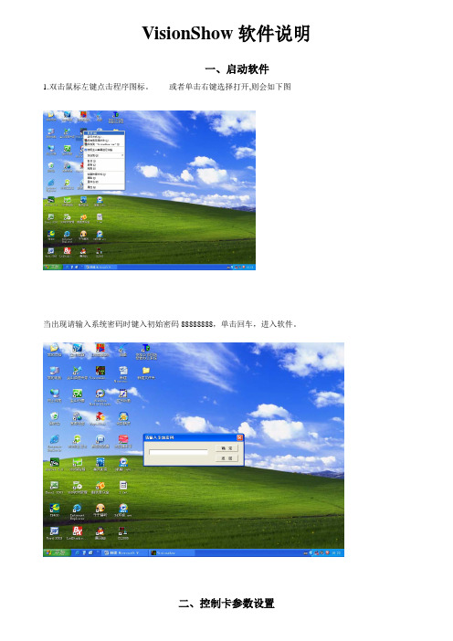
VisionShow软件说明一、启动软件1.双击鼠标左键点击程序图标。
或者单击右键选择打开,则会如下图当出现请输入系统密码时键入初始密码88888888,单击回车,进入软件。
步骤1:在菜单栏选择系统设置控制卡设置,输入系统密码键入初始密码88888888单击回车。
系统设置控制卡设置步骤2:进入控制卡设置界面,单击建立通讯与显示屏控制板建立通信。
备注:每次要输入新的数据都要进行建立通讯建立通讯界面上出现读取控制卡参数正常控制卡地址=00 说明计算机与控制卡连接正常步骤3:参数设置1、基本参数设置高度、宽度、通讯方式、串口号、IP地址高度:LED显示屏纵向点数宽度:LED显示屏横向点数通讯方式:串口通讯或是网络通讯串口号:串口通讯时,串口的选择。
IP地址:网络通讯时,设置IP地址2、扫描输出参数设置单击扫描输出参数(1)设置控制信号特性极性相反选择不正确时为黑字黄底色使能相反选择不正确时屏幕非常的暗逆向扫描选择不正确时字是显示镜像行取反选择不正确时字上下相反红绿反色选择不正确时发红时出绿字根据显示屏出现的现象选择!(2)设置扫描方式选择选择通讯方选择串口高度宽度IP地址的设置步骤4:将设置好的参数下载到主板,主板将按照新的参数运行。
扫描输出参数控制信号特性扫描方式选择单击设置参数:将设置好的参数下载到主板,主板将按照新的参数单击“是”控制板的基本设置参数完成单击“是”控制卡设置完成控制卡设置成功步骤1:单击一下控制卡,设置高度、宽度、通讯方式、宽度和高度的设置根据显示屏的横、纵点数来设置,设置后显示的黑屏就是显示屏的虚拟屏。
通讯方式的设置根据连接的方式是串口通讯还是网络通讯。
控制卡黑屏步骤2:单击显示页面设置,设置所发数据在显示屏上显示的时间。
时间以秒计算显示设置页面显示时间设置步骤3:添加数据,在红色框里选择添加自己所要添加的文本、word对象、图片、时钟。
选择添加数据样实例:通常我们使用的是“单行文本”出现如下图所示然后在单行文本上双击鼠标左键,如下图示在此处单击后增加“单行文本”在文字输入窗口中输入要发送到屏幕上的文字例如“欢迎光临依格电子”后再单击”确定”按钮如下图注意:一定要单击确定才能保存改变文字单击此处更改字此处更改数字改变字大小此处更改字的进入方式也可以用鼠标拖动文本框的边角上的白方块改变大小,点住左键来移动文本框的位置.总而言之:整个文本框的.字的颜色,大小,尺寸,位置, 显示方式(左滚动右滚动上翻页等)各种属性都在”对象属性的对应栏里更改.当更改完成后:我们再单击”显示页面1”单击这里把改好的内容发送到屏幕上(图1—1)在此处修改这个页面显示的时间设置页面的显示时间和显示速度:页面显示时间从0—999999999秒选择,单行文本字最多可以输入32768个汉字.显示速度一级最慢,八级最快.这样我们就完成了单行文本的输入,然后单击上面(图1-1)标注的位置的类似卫星的图标发送容到显示屏上.,单击”添加显示页”然后再重复上面的添加文本的操作,三.增加时间窗口比较重要的是”时间格式属性:这里可以选择: 年月日格式 ,但是只能选择一种,如果想要年单击此处增加时间窗口在此对象属性栏中修改日期时间的属性.和单行文本的修改类似,修改完成后把位置调整好,再发送到屏幕上再次单击增加,再排好位置月日,时分秒都显示的话,需要再增加一个”日期时间”然后排好两个日期时间窗口的位置,选好时间格式.再发送到显示屏上.。
全能视觉软件说明书(视觉)2015.9.28

视觉联机激光控制软件-使用说明书-深圳市智远数控有限公司目录上层软件使用操作说明第一章驱动和软件的安装 (2)1.1 数控系统软件简介 (3)1.2 控制系统的组成 (3)1.3 驱动和软件的安装 (3)1.3.1视觉驱动MIL的安装与卸载 (4)1.3.2视觉切割软件的安装 (10)1.4软件特点 (13)1.5单反相机应用步骤 (14)1.6界面说明 (15)第二章设备参数的设置 (17)第三章工作面板 (21)3.1 图层管理 (21)3.2 手动控制 (23)3.2.1标定管理 (24)3.2.2 模版切割设置 (29)3.2.3 寻边切割设置 (38)3.2.4寻边切割功能对材料要求 (40)3.3设备控制 (40)3.4加工信息 (41)底层软件/硬件使用说明及接线 (42)第一章概述 (42)1.1 系统功能 (42)第二章安装接线说明 (43)2.1 安装尺寸 (43)2.2 接线说明 (44)2.21 接口板 (44)2.22 接线图 (44)2.3 端口定义说明 (47)2.32 U盘接口 (48)2.33 PC接口 (48)2.34 网络接口 (48)2.35 端口定义 (48)第三章常见问题排除 (51)3.1 电脑连接问题 (51)3.2 U盘读写问题 (51)3.3 相机连接问题 (51)3.4 问题现象: (51)3.5 机器不动作 (52)第四章经典激光切割机接线图 (53)4.1 标准激光切割机接线图 (53)第一章驱动和软件的安装1.1 数控系统软件简介PowerCut视觉激光切割控制软件是深圳市智远数控有限公司集多年行业经验、业内知名研发团队精心打造的一款激光切割数控精品。
该软件简单易学、运动控制算法成熟稳定、切割工艺完备、人机交互界面友好,适用于服装、亚克力、家俱等非金属激光切割控制。
1.2 控制系统的组成控制系统由硬件(运动控制卡及配件)和软件两部分组成。
(完整word版)VISION中文的使用说明
NI Vision 控件模板Vision控件模板位于LabVIEW控件模板的最顶层,由一下元素组成:IMAQ Image.ctl—该控件是一个类型定义,用于声明图象类型的数据。
在V I的前面板中使用该控件代表图象类型数据。
例如,使用该控件作为一个子程序的输入或输出,使调用成成可以将一幅图像传送给子程序。
图像显示(Image Display)—该控件用于在LabVIEW 中直接显示图像。
也可以利用该控件创建关注区域 (ROIs)。
图像显示控件提供标准和3D版两种外观。
IMAQ 视觉控件(IMAQ Vision controls)—这里的控件用于将NI Vision的程序控件直接加入入用户自己的程序中获得相应的功能。
机器视觉控件(Machine Vision controls)—这里的控件用于将NI Vision 的机器视觉控件直接加入到用户自己的程序中以获得相应的功能。
NI Vision 函数模板NI Vision for LabVIEW 由三个主要的函数模板组成:常用视觉程序(Vision Utilities), 图像处理(Image Processing), 和机器视觉(Machine Vision)。
本节介绍这些模板以及它们的子模板。
常用视觉程序(Vision Utilities)常用视觉函数用于在NI Vision中处理和显示图像。
Image Management—管理图像程序组。
利用这些程序可以建立和释放图像,设置和读取图像的属性例如尺寸和偏移量,复制图象。
也可以使用一些高级的V is来定义图像的边框区域以及访问图像数据的指针。
Files—一组使用不同格式读、写图像文件,并从文件中获得所包含的图像的信息的程序模块。
External Display—用于在外部窗口显示图像的程序模块组。
使用这些程序模块可以完成以下任务:读取和设置窗口属性,如尺寸、位置、缩放系数为图像窗口设置调色板建立及使用图像浏览器在图像窗口上为选中的关注区域建立和使用不同的交互式绘图工具。
视觉软件说明文档
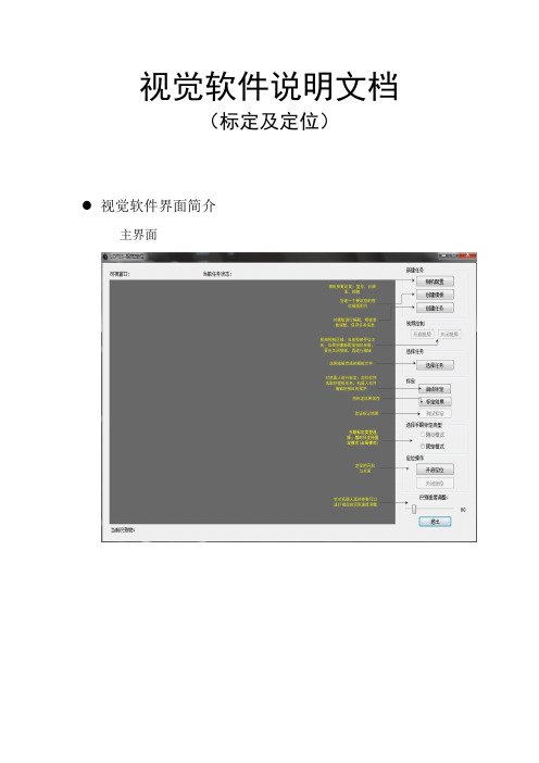
视觉软件说明文档(标定及定位)视觉软件界面简介主界面界面功能模块介绍1.可视窗口:实时视频的显示,物体识别显示,如下图所示:2.当前任务状态:当“鼠标”移动到该位置会弹出浮动提示,将显示当前相机参数,任务数量,模板参数等信息,如下图所示:3.相机配置:暂时只支持映镁精的相机,参数配置如下图所示:4.创建模板:点击按钮后,会自动截取一张完整的相应分辨率大小的图片,然后选取想要的区域,进行保存。
5.创建任务:点击后,会弹出如下窗口:1)选择相应的模板打开模板图片后,选择一个抓取点(这将是匹配参数的一部分) 2)选择算法后会弹出窗口进行参数的调节,如下图所示:注意事项:1.抓取点:不用自己输入(之前打开模板图片选择的抓取点就是改抓取点)2.金字塔层数越高,识别越快(相反的,识别度就会下降,建议选择4)3.边缘阈值下限/上限:上限值始终要保持大于下限值实时调整这项值,窗体下面会进行实时预览显示。
对照下面的判别方式,将值调整到合适为止好坏的判别方式:效果好:如下图效果差:如下图4.角度范围下限/上限:上限值始终要保持大于下限值如果是有角度:比如矩形等:范围一般设置为:0-360如果是没有角度的(或是细微的):比如圆形之类的,范围一般设置为:0-0.1 (上限值绝对不能设置为0)4.匹配阈值:范围是0-1:值越低:匹配度越低(拿类似边缘的也有可能识别到,对环境要求较低)值越高:匹配度越高(比如设置为1,那么将匹配一模一样的才行,对环境较高)推荐设置:光源做好后,匹配度一般设置为0.7-0.9之间6.保存好模板参数,保存任务名(请保存到当前视觉软件TaskTemplate目录下,格式为.ini)7.选择任务:任务支持单选,多选,追加8.启动标定:将相机固定好,并调整好位置,光源做好;选择好模板任务后,机器人软件:标定程序配置完毕后,点击按钮就能进行对机器人的标定。
标定时间需要15分钟左右!标定之前,请先启动机器人软件,标定模式为:固定模式(全局模式)9.标定结果:待标定完成后,点击此按钮,将会把标定文件保存到当前视觉软件CalibData目录下文件名为:calibration001.yml10.测试标定:测试标定文件是否正确,精度知否达标,视觉软件识别到物体后,机器人能否正确的抓取到识别物!操作简介:1:机器人操作软件,利用视觉模块编辑一段视觉相关的程序(具体参考机器人软件操作说明书)2:视觉定位软件,选择好手眼标定文件:点击“固定模式”复选框,选择calibration001.yml标定文件3:点击“测试标定”按钮即可观察11.手眼标定类型的选择暂时只支持固定模式,点击“固定模式”复选框,选择calibration001.yml标定文件12.开启定位选择好任务,手眼标定文件,点击此按钮就能和机器人软件配合做定位识别了13.关闭定位将停止定位识别14.识别速度调整在实际应用中,机器人软件编好程序后,里面将会用来延时等相关操作控制视觉定位,这个选项能配合机器人软件,通过调整参数值,达到想要的识别速度视觉标定操作(机器人部分)一,概述视觉标定的思路为:使用多个特征点分别在图像坐标系的像素坐标和机器人的空间坐标,来求得两个坐标系之间的影射关系。
康耐视视觉软件说明书
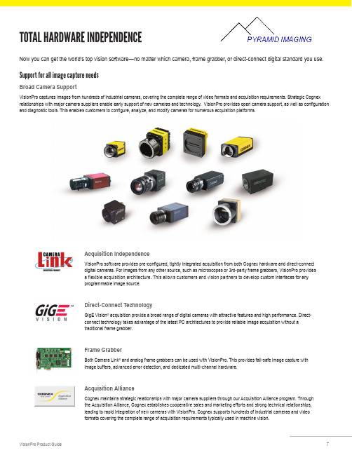
Now you can get the world’s top vision software—no matter which camera, frame grabber, or direct-connect digital standard you use.Support for all image capture needsBroad Camera SupportVisionPro captures images from hundreds of industrial cameras, covering the complete range of video formats and acquisition requirements. Strategic Cognex relationships with major camera suppliers enable early support of new cameras and technology. VisionPro provides open camera support, as well as configuration and diagnostic tools. This enables customers to configure, analyze, and modify cameras for numerous acquisition platforms.Acquisition IndependenceVisionPro software provides pre-configured, tightly integrated acquisition from both Cognex hardware and direct-connect digital cameras. For images from any other source, such as microscopes or 3rd-party frame grabbers, VisionPro provides a flexible acquisition architecture. This allows customers and vision partners to develop custom interfaces for any programmable image source.Direct-Connect TechnologyGigE Vision ® acquisition provide a broad range of digital cameras with attractive features and high performance. Direct-connect technology takes advantage of the latest PC architectures to provide reliable image acquisition without a traditional frame grabber.Frame GrabberBoth Camera Link ® and analog frame grabbers can be used with VisionPro. This provides fail-safe image capture with image buffers, advanced error detection, and dedicated multi-channel hardware.Acquisition AllianceCognex maintains strategic relationships with major camera suppliers through our Acquisition Alliance program. Through the Acquisition Alliance, Cognex establishes cooperative sales and marketing efforts and strong technical relationships, leading to rapid integration of new cameras with VisionPro. Cognex supports hundreds of industrial cameras and videoformats covering the complete range of acquisition requirements typically used in machine vision.TOTAL HARDWARE INDEPENDENCENotes:*1 Cognex Designer is only available with the Development dongle, VC5, CC24 Comm Card, or 8704E GigE Framegrabber*2 3D Measurements Tools are exclusive to the Cognex Displacement Sensor series。
易感视觉(VISION)说明书
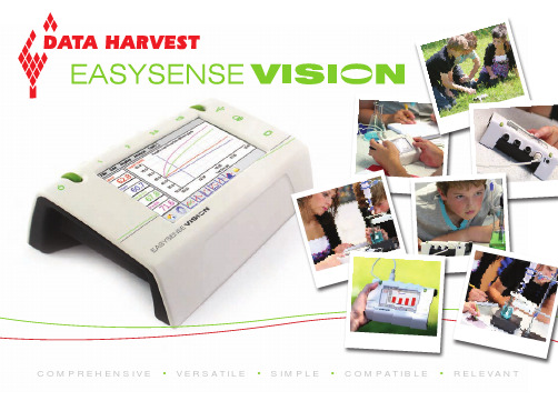
USB HostConnect: Mouse, Keyboard, Memory Stick, HP Printers (PCL)USB ClientConnect VISION to a PC to:• Transfer captured data from VISION to the PC for further analysis and reporting • Use VISION as an interface and capture data using the FREE PC software VGA ConnectionConnect VISION to any standard Projector or Monitor – Essential for teacher led presentations and student trainingHi Resolutionfull colour LCD displayWith the full EasySense software built-in. VISION has everything required to capture, display& analyse data.High Visibility Stylus (or use a finger!)Power Button (Instant on)COMPREHENSIVE • VERSATILE • SIMPLE • COMPATIBLE • RELEVANTOrder Code: 2020Heart Rate and Pulse Waveform Polar Heart Rate Exercise Sensor The SmartQ differenceBeneath SmartQ’s simple and bright exterior is a revolutionary architecture that dramaticallyenhances the intelligence, accuracy and value of our entire range of sensors. Among many of the remarkable improvements of the SmartQ design is the incorporation ➊ Low Cost USB Mini MouseOrder Code: 2031With a rectractable cable foreasy storage.➋ Low Cost USB Wireless Mini Mouse Order Code: 2032➌ Mini USB Keyboard Order Code: 2030An alternative to the on-screen touch keyboard.➍ USB Pen Drive (Memory Stick) Order Code: 2033Offers students a quick and low cost method of taking their experiment results to a PC, either in school or at home.➎ 4 Port USB Hub (Powered) Order Code: 2034Allows the connection of multiple USB devices simultaneously (Keyboard, Mouse, Pen Drive etc.) Carry Case Order Code: 2035Neoprene case, simple and robust design.Please note, VISION will operate with any standard USB Mouse, Keyboard, Pen Drive or USB Hub (Including wireless mice and keyboards etc.)St et ho sc op e ➋➎➍ACCESSORIESSo un d H e a r t R a t e a n d P u l s e W a v e f o r mC a r b o nD io x ide G a s VERSATILE • SIMPLE •SENSORS➌➊。
视觉定位软件VisionKit-软件说明书
文件名称:视觉定位软件VisionKit使用说明书文件版本:中文简体版文件页数:共 42 页(含此页)编制:审核:标准化:批准:日期:大族激光科技产业集团股份视觉定位软件VisionKit使用说明书(版本:中文简体版)大族激光科技产业集团股份.hanslaser.声明所有©大族激光科技产业集团股份保留一切权利。
未经大族激光科技股份的许可,任何组织和个人不得擅自摘抄、复制文档容的部分或全部,并不得以任何形式传播。
商标声明和其它大族商标均为大族激光科技产业集团股份的注册商标,并对其享有独占使用、许可使用、转让、续展等各项法定权利,未经大族激光科技产业集团股份允许,任何组织或个人不得在商品上使用相同或类似的商标。
注意在所规定的支持保修围,大族激光科技产业集团股份履行承诺的保修服务,超出所在规定的保修围的,恕不承担保修服务。
对于在使用本产品过程中可能造成的损失,大族激光科技产业集团股份不承担相关责任。
如发生任何争议,应按中华人民国的相关法律解决。
大族激光科技产业集团股份随时可能因为软件或硬件升级对使用说明书的容进行更新,所有这些更新都将纳入使用说明书新的版本中,恕不另行通知。
目录声明 (3)一、软件概述 (5)二、环境安装 (5)2.1环境要求 (5)2.2软件安装 (5)2.2.1 安装halcon基础软件 (5)2.2.2 安装相机驱动软件 (6)2.2.3注册串口通讯组件 (10)2.2.4 VIsionKit软件 (10)三、软件界面介绍 (10)3.1主界面 (10)3.1.1 主界面介绍 (10)3.1运行界面 (13)3.1.1 运行界面介绍 (13)3.2设置界面 (15)3.2.1 图像标定 (16)3.2.2 ROI设置 (18)3.2.3通信设置 (20)3.2.4 LED设置 (21)3.3参数界面 (22)3.3.1编辑定位集 (23)3.3.2定位模板下拉框 (23)3.3.3测试 (24)3.4诊断界面 (25)3.4.1图像操作 (25)3.4.2验证补偿 (27)3.4.3整体补偿 (27)四、CCD工作流程 (28)4.1相机标定 (28)4.2模板制作 (34)4.3生产运行 (38)4.4 误差校正 (40)五、软件操作注意事项 (42)附录A:软件定制功能 (42)附录B:术语解释 (42)附录C:技术支持与服务 (42)一、软件概述视觉定位软件VIsionKit是大族激光科技产业集团股份光纤打标产品线开发的一款定制的机器视觉定位软件,通过CCD视觉定位后将位置偏差数据发送至打标软件系统进行补偿校正打标,实现产品精确定位打标功能。
视觉测量系统简易模式产品说明书
Renton, Washington
NoteM: Aalsl oinnfo, rOmhaiotion
regarding
our
products,
and
in
particular
the
Houston, Texas illustrations, drawings,
dimensional
and
performance
© 2014 Mitutoyo America Corporation, Aurora IL
1.5M 0614-07 Printed in USA, August 2014
O1-n8e88N-uMmITbUeTrOtoYOSe(r1v-e88Y8o-u64B8WH(eC-uote8ntrs8eptteo6rforr9asrtdv)ei,HllMeea,adsNqsuoaarrctthehrusCs)aertotslina
Plymouth, Michigan
Mason, Ohio
Transmitted light: Green LEDOnteeleNceunmtribceilrlutmoinSaetriovne; YCou-axBiaeltLteigrht: White LED; Ring light: quadrant white LED 1-888-MITUTOYO (1-8280±81-6ºC48-8869)
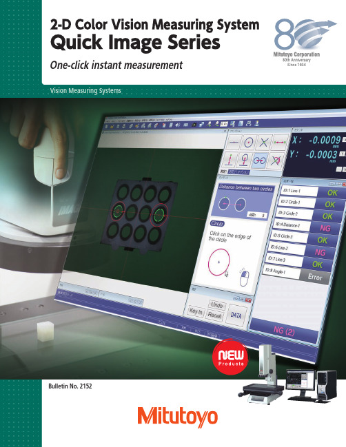
• Alignment of workpiece is automatically located via pattern recognition.
• Provides quick results of features (GO/NG/PASS/FAIL).
QIPAK Simple Mode
相机连接说明书
如果有 windows安 全警报或杀 毒软件报警, 请选择允许 安装
之后一直默认安装即可。。。。。
之后一直默认安装即可,连续出现的几个NEXT,点 击即可,直到下图驱动安装完成。。。。。
之后一直默认安装即可。。。。。
安装加密狗驱动
打开下面的文件夹
安装加密狗驱动
安装加密狗驱动
安装加密狗驱动
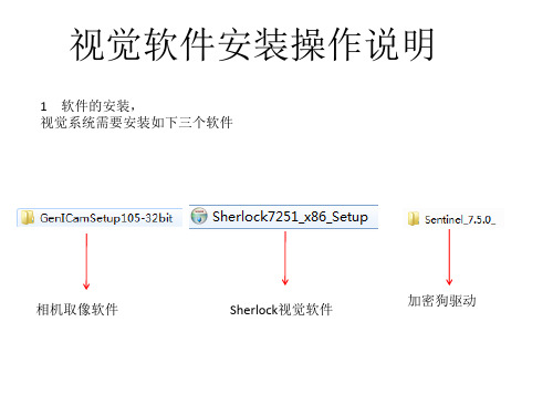
视觉软件安装操作说明
1 软件的安装, 视觉系统需要安装如下三个软件
相机取像软件
Sherlock视觉软件
加密狗驱动
硬件配置
1.相机、镜头、光源 2.相机配套电源线一根 3.配套网线一根 4加密狗驱动一个 5.工控机一台(32位操作系统)
软件安装
打开此文件夹,选择主安装程序右键选择以管改软件及相机配 置文件生成
相机IP地址的修改和配置文件的生成
相机IP地址的修改和配置文件的生成
点击,会在文件夹
发现一个文件名为gevtest的文本文件
相机IP地址的修改和配置文件的生成
确认此序列号为已连 接的相机的序列号 可以把此文件拷贝到D:\DALSA文件夹下,也可以是别的路径,但需要记住此 路径,之后Sherlock需要调用此文件
Sherlock软件调用相机配置文件 把此项内容设定为1,然后保存
Sherlock正确取像的确认 1 把软件的授权狗,插到电脑上,在开始程序,找到如下 位置
打开
Sherlock正确取像的确认
此两项为绿色表明加密狗的驱动安 装正确
Sherlock正确取像的确认 在打开的sherlock软件里,找到Options----Application
安装加密狗驱动
安装加密狗驱动
安装Sherlock程序
VISION中文的使用说明
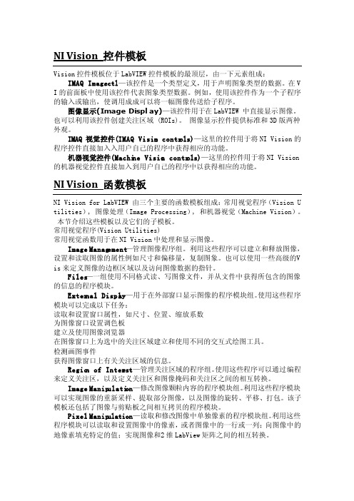
NI Vision控件模板Vision控件模板位于LabV IEW控件模板的最顶层,由一下元素组成:IMAQ Image.ctl—该控件是一个类型定义,用于声明图象类型的数据。
在V I的前面板中使用该控件代表图象类型数据。
例如,使用该控件作为一个子程序的输入或输出,使调用成成可以将一幅图像传送给子程序。
图像显示(ImageDispla y)—该控件用于在LabVI EW 中直接显示图像。
也可以利用该控件创建关注区域 (ROIs)。
图像显示控件提供标准和3D版两种外观。
IMAQ 视觉控件(IMAQ Vision contro ls)—这里的控件用于将NIVision的程序控件直接加入入用户自己的程序中获得相应的功能。
机器视觉控件(Machin e Vision contro ls)—这里的控件用于将NIVision 的机器视觉控件直接加入到用户自己的程序中以获得相应的功能。
NI Vision函数模板NI Vision for LabVIE W 由三个主要的函数模板组成:常用视觉程序(Vision U tilit ies), 图像处理(ImageProces sing), 和机器视觉(Machin e Vision)。
本节介绍这些模板以及它们的子模板。
常用视觉程序(Vision Utilit ies)常用视觉函数用于在NI Vision中处理和显示图像。
ImageManage ment—管理图像程序组。
利用这些程序可以建立和释放图像,设置和读取图像的属性例如尺寸和偏移量,复制图象。
也可以使用一些高级的V is来定义图像的边框区域以及访问图像数据的指针。
Files—一组使用不同格式读、写图像文件,并从文件中获得所包含的图像的信息的程序模块。
Vi软件操作说明书MO - 150420
Vision Inspector Software User Manual Vision Inspector软件使用说明版本:V1.0修订时间:2014.12说明:本手册适用于具备基础机器视觉知识的人员。
本软件可与Beckhoff、KEBA等机器人控制器直接通讯。
1简介Vison Inspector是一款针对于机器人应用的视觉软件。
用户无需编写代码,通过简单的拖拽等操作即可实现机器人所需的定位功能,将视野范围内目标物体的坐标,角度,产品属性等数据发送给指定控制器,引导机器人快速抓取运动中的目标物体。
Vision Inspector软件具备如下特点:支持多种相机实现坐标变换通过TCP/IP通讯具备流量均衡分配功能与多个机器人控制器协同工作Vision Inspector 软件界面如图1-1所示,右侧为菜单栏及对应命令、参数设置及显示,左侧为图像显示窗口。
图1-1 主界面Vision Inspector软件主菜单命令包括:Calibrate:校正Models:图片处理Matching:模板设置BalancingCamera:相机设置下面的章节内容将手把手教您如何使用Vision Inspector实现拍摄目标物体并将其坐标、角度、产品种类等信息通过TCP/IP正确传输给机器人控制器。
在继续阅读之前,请确保您已做好如下准备工作:1)基本图像处理知识2)一个具备GigE接口的相机及合适的镜头和光源3)一台已安装Vision Inspector软件的控制器4)一台安装有标定针的机器人5)标定纸(中心有十字架的四个圆)6)合格的目标物体2基本操作2.1相机设置确认您的相机已通过网线接入安装了Vision Inspector 软件的控制器。
打开Vision Inspector 软件,左键点击主菜单栏的Camera命令,可设置相机的各种参数。
当鼠标移动至相关参数显示框时,Vision Inspector 软件会自动显示参数的含义,如图2.1-1所示。
Viskon7木结构设计软件教程
Weto AG培训课程Viskon V7第一章: Viskon 基础知识1.1 新建,打开,保存 及自动备份在Viskon 中,您可以通过新建项目进行三维模型的绘制,并通过设置自动备份来进行项目的保护以及保存。
当我们需要继续绘制之前项目的时候,我们可以通过打开功能来继续模型的绘制。
在自动备份功能中,我们可以设置软件自动保存的时间间隔为1小时或者其它时间。
自动保存的文件数量为1份或者其它数量。
1.2 操作界面/ 功能键布局1.3 单位设置及其它预设置Viskon 的默认长度单位为厘米,同时软件增设了毫米、分米、米、英寸、英尺、码等长度单位供用户进行选择,并可设置保留小数点后几位数字。
具体步骤:菜单栏 → 设置 → 设置单位长度。
1.4 三维图与二维图纸之间的转换在软件操作界面的右上角视图栏中有三维视图、俯视图、左视图、右视图、前视图、后视图、透视图等命令供用户进行二维图与三维图之间进行切换。
标题栏 菜单栏 工具栏 创建工作区命令指示栏视图栏图层栏绘图栏第二章:基本绘图2.1掌握绘图基本流程:新建项目→建立基础平板→插入CAD平面图(或手动绘制二维墙体辅助线)→建立辅助墙体→调整转角链接→生成实际墙体→插入并调整门窗→屋顶助手绘制屋顶(或者用五点法)→插入桁架→模型完成2.2了解楼层、结构段、图层的概念楼层:在Viskon中有一个楼层管理。
它可以创建多个不同水平高度的楼层,并且显示或隐藏每一个楼层。
结构段:可以和楼层相类似地进行运用。
通过结构段可以使得楼层更好地被划分。
(比如,楼层=顶楼,结构段1=墙体,结构段2=屋顶)图层:其实就是可自定义的建筑部件独立组。
图层1 (A轴墙)结构段1 (墙体)楼层图层2 (B轴墙)结构段2 (屋架)2.3基础平板/平面的建立、移动及调整:在Viskon新建项目时会要求生成一块基础底板或平面,以便项目的绘制。
可通过选择点及复制来建立新的底板或平面。
删除开口:在此可以删除一个存在于平板/平面的开口。
3D Vision软件说明书

3DVison软件用户手册杭州先临三维科技股份有限公司目录1.前言 (2)2.3D Vision软件的安装 (3)3.3D Vision 的操作界面 (6)4.三维水晶人像制作流程 (7)5.工具栏按钮的功能 (8)6.编辑功能工具 (9)6.1 模型生成及导入导出 (9)6.2 模型平移、旋转、缩放 (13)6.3背景切除 (13)6.4 选择工具 (14)6.5清除毛刺 (16)6.6填补空洞 (16)6.7 表面光滑 (16)6.8 网格化 (16)6.9 刷新 (16)6.10复位 (16)6.11模型调整 (17)6.12模型删除 (17)6.13镜像工具 (18)6.14坐标系转换 (18)6.15点云操作 (18)6.16数据输出 (25)6.17快捷键 (26)7.3D Vision 的使用案例指导 (27)7.1 立体模型的处理 (27)7.2 平面照片的处理 (34)7.3 添加文字 (38)7.4添加配饰 (40)1.前言欢迎您使用杭州先临三维科技股份有限公司的三维成像软件3D-Vision。
本软件功能强大,界面简洁。
配合本公司研制的三维相机M1、M2,可以生成真实的立体模型,并对模型进行编辑,以实现各种用途。
同激光内雕机配合,制作三维立体人像水晶,是本软件的一个重要用途,在这项用途上,本软件具有如下主要优点:1.操作简便,可以快速生成三维人像的点云文件。
2.生成的数据效果好,使雕刻在水晶里的人像清晰、明亮、细腻。
3.具有强大的编辑功能,可以:对三维人像点云进行编辑处理,对二维照片进行点云编辑处理,添加文字,添加平面或者立体的个性化配饰,并进行组合编辑。
4.可以输出多种常规格式的数据,包括DXF(适用于主流的的激光内雕机),ASC,CAD,3DS(3DMAX),OBJ。
三维人像水晶内雕是一款经典的个性化礼品,将人们的真实形象定格在水晶之中,永不褪变,使人们一生中难忘和珍贵的时刻,成为恒久的记忆。
视觉定位打标使用手册

视觉定位打标使用手册ur-softv5.3 (视觉定位打标)用户手册第1章序言谢谢你选用我司视觉定位打标系统—ur welding!该手册对控制系统中提供的功能做详细的解释与说明。
手册的说明如未与控制系统的实际功能同步更新时,请以控制系统提供的功能为准。
给您带来不便,敬请谅解!任何时候有需要,请联系设备供应商。
第2章软件与驱动安装2.1软件的安装ur welding为绿色版软件,免安装。
直接拷贝文件夹到指定磁盘位置或将文件夹中的所有文件拷贝到目的文件夹即可。
2.2加密狗驱动的安装将软件狗插入电脑的USB接口,找到ur-welding软件所在文件夹下的Driver文件中的HASPUserSetup.exe,鼠标双击执行,弹出如图2.2.1对话框:图2.2.1开始软件狗驱动安装连续选择两次“Next>”,完成安装。
如图2.2.2。
图2.2.2软件狗驱动安装完成2.3振镜卡驱动的安装安装振镜卡驱动前,请先确认振镜卡已与电脑连接。
右键单击“我的电脑”,左键单击“管理”,弹出系统管理窗口,如图2.3.1所示。
图2.3.1在系统管理窗口中,选择“性能”->“设备管理器”,在设备管理器列表中扫描检测硬件改动,在“其它设备”里选中对应设检测到的新设备,右击选择“更新驱动程序软件”。
如图2.3.2。
图2.3.2选择“浏览计算机以查找驱动程序软件”,点击“浏览”,找到对应的驱动程序。
如图2.3.3图2.3.3点击“下一步”直至软件安装成功。
如图2.3.4。
图2.3.4此时,可在设备管理其中查看到硬件设备。
如图2.3.5。
如图2.3.52.4相机驱动的安装找到软件所在文件夹内的Driver文件夹,鼠标双击执行MCam30_SDK(32bit)_V3.0.0.8.exe,如下图所示:图2.4.1连续选择两次“Next”,弹出如图2.4.2对话框:图2.4.2点击“Install”,到如图2.4.3:图2.4.3连续点击两次“下一步”,到如图2.4.4:图2.4.4点击“我接受”,到如图2.4.5:图2.4.5点击“下一步”,到图2.4.6:图2.4.6点击“安装”,“完成”,图2.4.7:图2.4.7找到软件所在文件夹内的Driver文件夹,鼠标双击执行MCamU_Basic_2.1.1.1_x86.exe,弹出如图1.4.8对话框:连续点击两次“Next”,进入图2.4.9:图2.4.9点击“Install”,完成安装。
1 Smart Vision Development Kit 使用指南说明书
Smart Vision Development KitFAQsVersion 1.3June 16th, 2015I.Revision History:Table of ContentsI. Revision History: (2)II. General Questions: (4)1. What does the SVDK kit include? (4)2. Who are the SVDK partners and what value is supported by them? (4)3. Are other imager boards supported? (5)4. Are other PicoZed modules supported? (5)5. Can the imager board specification be supplied to customers to add their own imager? (5)6. Where do I get technical support? (5)7. Where do I get training? (6)8. Will my firewall cause issues with the demo? (6)9. In the log window of the Sphinx Viewer I see some packet loss indicated, is this normal? (6)10. Can I use every USB3 capable computer? (6)11. In U3V Sphinx Viewer I see Buffer OVERRUN messages in log files. What does it mean? (6)12. How do I re-program the SVDK for different demos? (6)13. Are the software drivers for the Aptina board available? (7)14. Are the evaluation designs on the SVDK time bombed protected? (7)15. Is it possible to use HALCON in combination to Silicon Software’s eVA? (7)16. Where can I get demo/trail version of HALCON? (7)17. Where can I buy Sensor to Image connectivity IP? (7)18. Where can I get evaluation/production version of HALCON? (8)19. Where can I buy HALCON? (8)20. Where can I get evaluation/production version of VisualApplets? (8)21. Where can I get VisualApplets documentation? (8)22. Where can I buy VisualApplets software? (8)III. Contact details: (9)II.General Questions:1.What does the SVDK kit include?⏹Development Board:o PicoZed (Zynq-7015) SOM moduleo Machine Vision Carrier Cardo Aptina 1.2MP camera moduleo Universal Power Adapterso Mini-USB-B to USB-A cableo Ethernet cableo Vivado Design Edition – Device Locked⏹Documentation (All accessed via ):o Quick Starto Getting Started Guideo Hardware User Guide⏹Further information available after registering with Sensor to Image:o Registration: http://www.sensor-to-image.de/index.php/products-mainmenu-33/registrationo Reference designs and easy to use demo instructions for machine vision connectivity from partner Sensor to Image : 1) GigE Vision, USB3Vision & CXP (Coaxpress) o All documentation and .exe files such as the Sphinx viewer software from Sensor to Image (GigE Vision viewer)o The carrier boards and Aptina sensor board schematic (in GERBER) fileso Standard reference design C-sources which includes routines for imager (AR0134) setup and basic controlo Tutorial from Sensor to Imageo Encrypted HDL and source files allowing modification of the reference design▪Video processor block and imager interface HDL (one module) which comes in sources▪Frame buffer, GigE Vision Core and Gigabit EMAC are delivered as encrypted HDL (time bombed evaluation IP)2.Who are the SVDK partners and what value is supported by them?Here is a list of the partners and what they provide for the kit:⏹Xilinx →Provides all programmable FPGA solutions. Zynq-7015 is used on PicoZed SOM.⏹Avnet→ Manufacturer and distributor of the kit⏹MVTec→ Provides demo version of their leading machine vision software, HALCONEmbedded, running on the SVDK with full library functionality. This software is fullyprocessor based.⏹Sensor to Image→ Provides reference designs for innovative machine vision connectivity(GigEVision, USB3Vision, CXP) implemented using their IP cores, support & registrationplatform, backend support on hardware for AVNET/XILINX/MVTEC⏹Silicon Software→ Provides innovative Embedded VisualApplets (eVA) tool as anevaluation version on SVDK for producing accelerated vision systems with a GUIprogramming flow3.Are other imager boards supported?Other imager boards are being planned but at this time only the Aptina imager AR0134 is supported.4.Are other PicoZed modules supported?Yes, PicoZed Zynq-7010 and Zynq-7020 are electrically compatible but with following limitations.⏹When Zynq-7010 PicoZed inserted into the SVDK: PMOD, CXP-In, CXP-OUT, HDMI will notwork⏹When Zynq-7020 PicoZed inserted into the SVDK: CXP-In, CXP-OUT, HDMI will not workFor available machine vision reference design it is necessary to contact ISM marketing to request support using these SOMs.5.Can the imager board specification be supplied to customers to addtheir own imager?Please contact Xilinx if there is interest in obtaining the specification.6.Where do I get technical support?The kit provides an out of the box experience for machine vision users that want to evaluate Zynq. The kit is low cost and does not come with any technical support package from Sensor to Image and the associated designs are supported by Xilinx Worldwide Technical Support (WTS). A tutorial and encrypted HDL files are available from the Sensor to Image web site (after registration) that will help customers take the reference design and adapt into their applications.Below is a quick guide on where to get general support for the Xilinx tools, hardware and questions on the reference designs:⏹Xilinx Vivado tools = Xilinx or Silica FAE and Xilinx WTS⏹Xilinx PetaLinux = Download area for PetaLinux, for customer hardware, can be found here:/PetaLinux⏹PicoZed SoM, = Avnet. Note is a portal for evaluationdocumentation with SVDK, for technical questions not covered by the documentation on this site please contact the relevant partner directly⏹GiGE Vision, USB3 Vision & CXP Reference designso Sensor to Image ticket support system▪Only for SVDK customers that have registered and access granted⏹Some general technical points are covered in this FAQ⏹MVTec HALCON support is as followso Customers need to read FAQ, Getting Started and Tutorialo Customers can contact MVTec directly via their Solutions email address at the bottom of this document7.Where do I get training?The kit is supported with getting started and tutorial documentation. No formal training is available at this time but please contact Xilinx marketing if you wish to register your interest in future events that are being planned.8.Will my firewall cause issues with the demo?Yes the firewall setting on the PC could cause an issue with the demos running. Being able to ping the hardware is not enough as ping, discovery and control channel works regardless the firewall settings, but streaming (runs on different port) is usually blocked by the firewall. The software included adds itself to firewall, but it needs administrator privileges. To test if streaming works we recommend sending a test packet.9.In the log window of the Sphinx Viewer I see some packet lossindicated, is this normal?Yes, as it is likely that the setup on the PC side (receive) is not optimal. GigEVision systems generally make use of a special filter driver that ensure maximum throughput on the PC side. Such a driver is also available from Sensor to Image as a paid item.10.Can I use every USB3 capable computer?Actual performance of USB3 is dependent on USB3 chipset, its connection to the PCIe bus and drivers. Especially USB3 addon board often have poor performance compared to onboard interfaces. So S2I cannot guarantee that the demo design runs on every PC.Official test PC for USB3 Vision certification follows as much as possible to USB-IF’s official test setup and uses a laptop with the Intel HM87 chipset, specifically a Dell Latitude 3440 together with the latest Microsoft XHCI driver.11.In U3V Sphinx Viewer I see Buffer OVERRUN messages in log files.What does it mean?The U3V reference design uses no external memory to buffer data, only a small fifo. If now PC is blocked for some reason and cannot serve the USB interface for a while, this internal fifo overruns and the image is corrupted. To signal this to the application the overrun status flag is set. This may happen on PCs with poor USB performance, see previous question. 12.How do I re-program the SVDK for different demos?The SVDK is provided pre-programmed with the GigE Vision reference design supplied by Sensor to Image. If the user needs to evaluate another IP reference design or a different partner solution then it is necessary to reprogram the SVDK with an appropriate JTAG programming cable. The instructions to do so are included in Getting Started Guide. Such a cable is not included in the kit as every effort has been made to keep the cost of the kit low. It is expected that most designers will already own such a programming cable.13.Are the software drivers for the Aptina board available?The SVDK supports two different drivers depending on the use case:⏹Bare metal implementation with AR0134 sources are provided after registration with Sensorto Image.⏹V4L2, Video for Linux Drivers for the AR0134 are also available on request from Sensor toImage as a paid for item.14.Are the evaluation designs on the SVDK time bombed protected?Yes the partner solutions have the following time out periods⏹Sensor to Image –30 mino Hardware can also support a paid design on the hardware with no time bomb)⏹Silicon Software Embedded Visual Applets –30 min⏹MVTec HALCON software –30 mino SVDK is for evaluation of HALCON only. Contact MVTec for more information on customer implementations on their hardware.15.I s it possible to use HALCON in combination to Silicon Software’seVA?eVA is designed to work in combination with HALCON, i.e. HALCON on the PS of Zynq and eVA in the PL. At this time, there isn’t a demonstration for the SVDK for this but we would encourage dialogue with Silicon Software for customer specific requests.16.Where can I get demo/trail version of HALCON?This will be hosted on Sensor to Image website.Please register here to get username and password for HALCONtrial access.http://www.sensor-to-image.de/index.php/products-mainmenu-33/registrationAccess the below link for demo/trial version:https:///There will be a folder called HALCON.17.Where can I buy Sensor to Image connectivity IP?Please follow the below link:⏹http://www.sensor-to-image.de/index.php/kontaktfomular18.Where can I get evaluation/production version of HALCON? Please contact MVTec below:⏹/halcon/support/19.Where can I buy HALCON?Please follow the below link:⏹/halcon/sales/20.Where can I get evaluation/production version of VisualApplets? Please contact Silicon Software below:⏹/en/contact.html21.Where can I get VisualApplets documentation?Please follow the below link:⏹/en/products/239-va-svdk-en.html22.Where can I buy VisualApplets software?Please follow the below link:⏹/en/sales-menu.htmlIII.Contact details:Please contact your sales representative/FAE or follow the links below: Xilinx Inc./about/contact.htmlAvnet/en-us/contact-us/Pages/default.aspx MVTec (HALCON)*******************Sensor to Imagehttp://www.sensor-to-image.de/index.php/kontaktfomularSilicon Software (Embedded Visual Applets)/en/contact.html。
- 1、下载文档前请自行甄别文档内容的完整性,平台不提供额外的编辑、内容补充、找答案等附加服务。
- 2、"仅部分预览"的文档,不可在线预览部分如存在完整性等问题,可反馈申请退款(可完整预览的文档不适用该条件!)。
- 3、如文档侵犯您的权益,请联系客服反馈,我们会尽快为您处理(人工客服工作时间:9:00-18:30)。
文件名称:视觉定位软件VisionKit使用说明书文件版本:中文简体版文件页数:共42 页(含此页)编制:审核:标准化:批准:日期:大族激光科技产业集团股份视觉定位软件VisionKit使用说明书(版本:中文简体版)大族激光科技产业集团股份.hanslaser.声明所有© 大族激光科技产业集团股份保留一切权利。
未经大族激光科技股份的许可,任何组织和个人不得擅自摘抄、复制文档容的部分或全部,并不得以任何形式传播。
商标声明和其它大族商标均为大族激光科技产业集团股份的注册商标,并对其享有独占使用、许可使用、转让、续展等各项法定权利,未经大族激光科技产业集团股份允许,任何组织或个人不得在商品上使用相同或类似的商标。
注意在所规定的支持保修围,大族激光科技产业集团股份履行承诺的保修服务,超出所在规定的保修围的,恕不承担保修服务。
对于在使用本产品过程中可能造成的损失,大族激光科技产业集团股份不承担相关责任。
如发生任何争议,应按中华人民国的相关法律解决。
大族激光科技产业集团股份随时可能因为软件或硬件升级对使用说明书的容进行更新,所有这些更新都将纳入使用说明书新的版本中,恕不另行通知。
目录声明 (4)一、软件概述 (6)二、环境安装 (6)2.1环境要求 (6)2.2软件安装 (6)2.2.1 安装halcon基础软件 (6)2.2.2 安装相机驱动软件 (7)2.2.3注册串口通讯组件 (11)2.2.4 VIsionKit软件 (11)三、软件界面介绍 (11)3.1主界面 (11)3.1.1 主界面介绍 (11)3.1运行界面 (14)3.1.1 运行界面介绍 (14)3.2设置界面 (16)3.2.1 图像标定 (17)3.2.2 ROI设置 (19)3.2.3通信设置 (21)3.2.4 LED设置 (22)3.3参数界面 (23)3.3.1编辑定位集 (24)3.3.2定位模板下拉框 (24)3.3.3测试 (25)3.4诊断界面 (26)3.4.1图像操作 (26)3.4.2验证补偿 (28)3.4.3整体补偿 (28)四、CCD工作流程 (29)4.1相机标定 (29)4.2模板制作 (35)4.3生产运行 (39)4.4 误差校正 (41)五、软件操作注意事项 (43)附录A:软件定制功能 (43)附录B:术语解释 (43)附录C:技术支持与服务 (43)一、软件概述视觉定位软件VIsionKit是大族激光科技产业集团股份光纤打标产品线开发的一款定制的机器视觉定位软件,通过CCD视觉定位后将位置偏差数据发送至打标软件系统进行补偿校正打标,实现产品精确定位打标功能。
视觉定位打标系统通常由CCD定位软件、具有数据通讯和偏位补偿功能的打标软件系统、以及数据通讯网络(COM232或IP/TCP网络)等三大模块组成。
二、环境安装2.1环境要求操作系统:Windows XP以上,推荐Windows 7(32)位系统,暂不支持64位系统。
最低硬件配置:CPU:赛扬1G以上;存:至少1GB,建议2GB以上;硬盘:至少500MB可用空间,建议预留更多的可用空间。
2.2软件安装2.2.1 安装halcon基础软件(1)如下图示分别需要安装halcon-10.0-images-windows.exe和halcon-10.0-windows.exe。
(2)注意事项:安装halcon-10.0-windows.exe过程中需要勾选安装如下驱动,其他选择默认安装即可。
2.2.2 安装相机驱动软件(1)根据相机类型选择如下驱动安装。
(2)安装相机驱动程序Vimba_v1.4_Windows.exe.等待安装进度完成:选择安装Vimba驱动:等待驱动安装完成安装OK,即可测试连接相机:2.2.3注册串口通讯组件注册串口控件,当打开软件异常无反应时,需要注册下串口OCX控件,见下图。
运行RegCom.exe程序,选择注册MSCOMM32.OCX组件。
2.2.4 VIsionKit软件三、软件界面介绍3.1主界面3.1.1 主界面介绍1、开启视频。
点击后,CCD会实时拍照,按钮切换显示为“停止视频”;2、单抓取。
CCD进行一次拍照;3、用户登录。
进行权限编辑。
如下图:4、产品文档管理。
添加和编辑用户不同的产品文档信息。
如下图:5、工具栏。
软件的主体功能区,下面会详细介绍。
3.1运行界面3.1.1 运行界面介绍1、如上图,点击开始运行,即代表软件进行待生产模式。
2、点击红框处停止运行,软件即停止运行。
3.2设置界面3.2.1 图像标定如上图: 在进行标定时,需选择适当的参数提取黑圆或者白圆,获取中心,并与激光坐标一同创建一个坐标系矩阵,用于坐标换算。
以下讲解标定详细过程:1、鼠标单击画ROI按钮;2、在图像窗口中绘制一个包含六个标定点的矩形框;3、选取适当的参数提取白色圆;4、点击“识别圆心”,即获取到6个白色圆心坐标;5、单击“获取激光数据”,即获取到相对应的激光坐标,如下图:6、点击“标定”,即生成矩阵文件,完成标定,如下图:标定完成。
3.2.2 ROI设置1、工位的选择。
每个工位都是一组独立的数据;2、选择绘制的类型,矩形或者圆,如下图:3、操作运算。
在绘制的选择上,可以选择交集、并集和差集的逻辑方式。
可实现复杂图形的绘制;4、区域组的选择。
每个工位可绘制N个区域,添加工位的方法如下图:5、区域显示列表。
显示已经添加的区域;6、区域列表编辑栏。
可进行区域的删除、保存和测试操作。
1、通讯方式的选择。
可选择“串口控件方式”和“拷贝存方式”;2、串口控件的参数设置。
可进行串口号、波特率、校验位、数据位等等操作;3、发送数据和接收数据通讯测试栏。
1、工位的选择。
每个工位都有独立的光源参数;2、软件控制光源的串口控件编辑;3、光源参数的设置。
通道数一般为2或者4,设置亮度值,然后点击“设置”按钮,即可应用和保存;4、相机的曝光值。
可设置相机的曝光值,值越大图像越亮,但同时噪点会变多。
3.3参数界面3.3.1编辑定位集1、点击“编辑定位集”按钮,弹出定位集管理对话框,可进行增删改查操作。
3.3.2定位模板下拉框1、显示已经制作完成的模板名称。
3.3.3测试1、所有流程设置完成后,点击“测试”按钮,即可获取物料定位的信息。
3.4诊断界面3.4.1图像操作1、打开图像,如下图:2、保存图像,如下图:3、“离线”按钮的勾选。
当手动打开一幅图像,需要处理时,可选择“离线”模式。
此模式下,CCD不进行采图,而是处理手动打开的图像。
3.4.2验证补偿1、工位的选择。
所有工位的补偿值都是独立的;2、区域组的选择。
每个工位可以有多个区域,当然也就多个补偿值参数;3、开启单点验证。
鼠标在CCD显示界面左键单点,然后激光会在单点的位置打一个十字叉;4、如发激光打出来稍有偏差,可在此进行补偿;5、放大显示打出的十字叉,可直观的查看偏差与否。
3.4.3整体补偿1、整体补偿是单个工位所有的工作区域一同补偿;2、一键将补偿值应用到所有工位;3、一键将单工位补偿值归零。
四、CCD工作流程4.1相机标定标定需准备如下工作:先分别设置打标软件和视觉VisionKit软件的串口参数。
再打标软件加载6点标定图档,在准备好的打标板上进行普通打标。
打标完成后,取消勾选“启用标准软件功能”,开启VisionKit软件采集图像如下:进行标定:1、鼠标单击画ROI按钮;2、在图像窗口中绘制一个包含六个标定点的矩形框;3、选取适当的参数提取白色圆;4、点击“识别圆心”,即获取到6个白色圆心坐标(注意抓取白圆顺序需和图档点顺序一致);5、单击“获取激光数据”,即获取到相对应的激光坐标,如下图:6、点击“标定”,即生成矩阵文件,完成标定,如下图:标定完成。
标定完成后需要验证标定精度,操作如下:开启打标软件,并加载标定验证的打标图档(图档中心画一个十字架即可),并打开普通打标方式。
在VisionKit中“开启视频”,单击“单点验证按钮”,在图像任意位置点击,可以看到鼠标点击位置激光打出十字架,在右侧小窗口检查激光打出的白色十字架是否和窗口显示的绿色十字架完全吻合。
如果有偏差可以建立区域组并选择对应的区域,并在区域组补偿值中填写需要的补偿值,重复测试直到完全吻合。
(相关详细操作可参考3.2.2ROI设置和3.4.2验证补偿章节容)4.2模板制作点击添加按钮,进入模板制作界面,如下图。
点击模板区域。
点击更新训练图。
1、选择“矩形”;2、然后点击“添加”;3、在右方图像编辑框,鼠标左键绘制一个距形区域,大小刚好将需定位部分框住为合适。
绘制完成后,单击“创建模板”按钮,可以得到模板轮廓,制作完成;选中1,点击编辑参考点按钮,移动参考点到打标图档中Mark点位置,默认参考点为模板匹配定位点即模板区域的中心位置。
例如:Mark点位置在打标图案P的中心,则参考点也设置在中心位置即可。
点击保存按钮,保存模板为1.vs。
退出点击确定,可以看到我们新建的模板。
单击测试,可看到图像窗口显示OK,(如果设置过参考点并需使用则记得在运行时勾选“取参考点定位”)如下所示。
模板建立成功。
4.3生产运行运行VisionKit软件,点击开始运行;打开打标软件,加载生产打标图档。
点击“通用打标方式”,在弹出界面点击开始。
可以看到VisionKit软件,采集图像,定位产品成功。
注意:打标软件“设置-当前CCD模板工具集名设置”中的名称需要和模板名称一致。
4.4 误差校正如果定位打标发现位置有细微偏差,可以进行校正。
在整体补偿处设置需要补偿的数值,再点击“应用于全部工位”。
五、软件操作注意事项1、所有需在界面绘制的功能,必须点右键结束,否则容易造成软件卡死;2、当相机初始化失败时,请先检查驱动是否安装成功,再检查采集卡和数据线是否存在问题;附录A:软件定制功能说明:对客户定制的功能和说明通过附件的形式述附录B:术语解释说明:对说明书容中的专用术语、英文缩写和其它需要解释的概念进行述。
附录C:技术支持与服务说明:对客户在使用过程中遇到问题的处理办法和方式说明,注明联系地址、、、网址等。
