MOOG穆格D661-G...A中文样本
莫尔尔商品说明书

MLR010024N Mueller 4 Blade Onion Chopper B07SVBY6BH MLR010015N Mueller Julienne Vegetable Peeler B07PWG9BBX MLR010017N Mueller Conical Burr Grinder B0833F31MS MLR010006N Mueller Deluxe Knife Set Acrylic Stand B08BBD95WG MLR010555N Mueller Electric Coffee Grinder (Black)B08WC8TYXL MLR010556N Mueller Electric Coffee Grinder (Gray)B08WC6RHQ7 MLR010554N Mueller Electric Coffee Grinder (Red)B08WC371TP MLR010018N Mueller Electric Hand Mixer B08B2ZWLT6 MLR010008N Mueller French Press B07JGBK6XV MLR010001N Mueller Hand Blender B075X1KPLZ MLR010553N Mueller Hand Mixer (Black)B08WC7DR9B MLR010551N Mueller Hand Mixer (Red)B08WD13RG3 MLR010552N Mueller Hand Mixer (White)B08WCJF86Q MLR010014N Mueller Handheld Vegetable V-Slicer B0854R2NDM MLR010019N Mueller HyperGrind Electric Spice/Coffee B076FJ92M4 MLR010011N Mueller 5L Salad Spinner - Large B07GH6GTH4 MLR010010N Mueller Mandoline Slicer B01CT63964 MLR010012N Mueller Mandoline Zester Pro B09S185RJQ MLR010020N Mueller Premium 1500W Electric Kettle B07TZ5YHJN MLR010004N Mueller Single Serve Coffee Maker B08CY7BQG6 MLR010022N Mueller Single Serve Coffee Maker B07PYPX7M9 MLR010005N Mueller Stainless Steel Knife Set With Block B08BBNCYN2 MLR010002N Mueller Steam Iron B082XJTJBS MLR010009N Mueller Stove Top Whistling Tea Kettle B07MNXLLZW MLR010007N Mueller Toaster Oven 4 Slice B078SD1JT8 MLR010016N Mueller Ultra 12-Cup Coffee Maker B0833FGJJN MLR010013N Mueller Ultra Chef Chopper B07NMV8TB1 MLR010021N Mueller Ultra Juicer B07D3C6NVL MLR010023N Mueller UltraPot 6Q Pressure Cooker B07Q5BZFLB MLR010003N Mueller Vacuum Sealer Machine B07J2SR7YT MU010138Mueller Manual Citrus Press (Black)B08R99XD8X MU010139Mueller Manual Citrus Press (Gray)B08R993YJK MU010140Mueller Manual Citrus Press (White)B08R9BJWF7 MU010268Meuller Meat Cleaver With Leather Sheath, 7-inch B0B4PYC1LQ MU010200Mueller 12-Cup Drip Coffee Maker B08TYTBX8X MU010021Mueller 2-Blade Chopper B01HC7BNJA MU010057Mueller 7-inch Cleaver Knife with Pakkawood Handle B08BX7136Z MU010332Mueller Airtight Food Storage Containers, 12-Piece Set (Blue)B09FYHR4J5 MU010333Mueller Airtight Food Storage Containers, 12-Piece Set (White)B09FYGKQRB MU010287Mueller Airtight Food Storage Containers, 14-Piece Set (Blue)B0B8FT5FMK MU010325Mueller Airtight Food Storage Containers, 14-Piece Set (Gray)B09FYMM8Q4 MU010335Mueller Airtight Food Storage Containers, 14-Piece Set (White)B09FP2HLKL MU010336Mueller Airtight Food Storage Containers, 24-Piece Set (Blue)B09FNSSM7P MU010326Mueller Airtight Food Storage Containers, 24-Piece Set (Dark Gray)B09FYKFXFM MU010337Mueller Airtight Food Storage Containers, 24-Piece Set (White)B09FP72KJ5 MH010049Mueller Anti-Fatigue Compression Mat - Large (Beige)B09TV7VGVV MH010051Mueller Anti-Fatigue Compression Mat - Large (Black)B09TV99GY5 MH010050Mueller Anti-Fatigue Compression Mat - Largel (Brown)B09TV8WGTZ MH010046Mueller Anti-Fatigue Compression Mat - Medium (Beige)B09TV5MPMJ MH010048Mueller Anti-Fatigue Compression Mat - Medium (Black) B09TV5MCY9 MH010047Mueller Anti-Fatigue Compression Mat - Medium (Brown)B09TV65CDV MH010043Mueller Anti-Fatigue Compression Mat - Small (Beige)B09TVHN6PV MH010045Mueller Anti-Fatigue Compression Mat - Small (Black)B09TV4ZY3SMH010044Mueller Anti-Fatigue Compression Mat - Small (Brown)B09TV5YDYR MU010201Mueller Avocado Slicer and Pitter B0B8LBQ79K CG010002Mueller Basketball Arcade B0BGK3W1W7 MU010274Mueller Cast Iron Skillet - 10 inch B0B4PYW5R7 MU010273Mueller Cast Iron Skillet - 12 inch B0B4PX747K MU010050Mueller Chef Knife B08B7WK4VW MU010076Mueller Citrus Squeezer (Beige)B08M9PQCM3 MU010078Mueller Citrus Squeezer (Gray)B08M9HG2NG MU010077Mueller Citrus Squeezer (Mocha)B08M8KCTYB MU010079Mueller Citrus Squeezer (Orange)B08M8YJ5Z6 MU010035Mueller Citrus Zester and Cheese Grater Set B07NMTWX8T MU010080Mueller Colander (Beige)B08MBBYKSV MU010082Mueller Colander (Gray)B08MBFK1TG MU010081Mueller Colander (Mocha)B08MBFDWYR MU010162Mueller ConvectionToaster Oven, 8-Slice B08TVZQSLK MU010344Mueller Corded Hair Clipper and Trimmer Kit B09H3N9RR5 MU010362Mueller Cordless Leaf Blower, 20V B09R74FC6Y B09BBNY8H7Mueller Digital Themometer (Gray)B08WNPSB81 MU010161Mueller Digital Themometer (Red)B08WNBYPK5 MU010182Mueller Dish Drying Rack With Utensil Holder - Small (Beige/Red)B08ZJW4WZX MU010183Mueller Dish Drying Rack With Utensil Holder - Small (Gray/Gray)B08ZJTGF8V MU010180Mueller Dish Drying Rack With Utensil Holder - Small (Gray/Green)B08ZJVDHHX MU010181Mueller Dish Drying Rack With Utensil Holder - Small (Mocha/Beige)B08ZJWH4N4 MU010184Mueller Dish Drying Rack With Utensil Holder - Small (White /Turquouise)B08ZJXDH5T MU010349Mueller Dish Rack - Large (Beige/Red)B09NB1GJ46 MU010347Mueller Dish Rack - Large (Dark Gray/Green)B09NB3229D MU010348Mueller Dish Rack - Large (Light Gray/Gark Gray)B09N9ZQWRW MU010345Mueller Dish Rack - Large (Mocha/Beige)B09NB3HJ33 MU010346Mueller Dish Rack - Large (White/Turquoise)B09NB1TZTZ MU010266Mueller Dish Rack - Medium (Beige/Red)B09NB21BJ3 MU010311Mueller Dish Rack - Medium (Gray/Gray)B09NB3FGY2 MU010312Mueller Dish Rack - Medium (Gray/Green)B09NB1VLNK MU010313Mueller Dish Rack - Medium (Mocha/Beige)B09NB2XNWL MU010322Mueller Dish Rack - Medium (White/Turquoise)B09NB1NCZ5 MH010052Mueller Double Waffle Maker, 1200W B09VRG6K5R MU010272Mueller Durablend 10-SPEED Blender B0B94R1KKY MU010132Mueller Ear Forehead Thermometer (White)B08Q76G3TX MU010236Mueller Electric Indoor Grill, 14-inch B0B9PZNR27 MU010054Mueller Electric Knife Sharpener B08BFCV94W MU010029Mueller Electric Toothbrush B07BSPKDSB MU010364Mueller Expandable Garden Hose, 50-foot B09V3J242G MU010148Mueller Flatware Organizer - Large (Beige/Red)B08SHZT3Z9 MU010149Mueller Flatware Organizer - Large (Green/Dark Gray)B08SJ85QJ8 MU010150Mueller Flatware Organizer - Large (Light/Dark Gray)B08SHT6PH7 MU010151Mueller Flatware Organizer - Large (Mocha/Beige)B08SHXH2L8 MU010153Mueller Flatware Organizer - Medium (Mocha)B08SVFGR7D MU010152Mueller Flatware Organizer - Medium (Beige)B08SHW6CTL MU010154Mueller Flatware Organizer - Medium (Dark Gray)B08SHYZNCV MU010155Mueller Flatware Organizer - Medium (Light Gray)B08STRM47N MU010156Mueller Flatware Organizer - Small (Beige)B08SV33QX5 MU010159Mueller Flatware Organizer - Small (Light Gray)B08SV6MF7S MU010157Mueller Flatware Organizer Small - (Mocha)B08SVTLCFR MU010301Mueller Flatware Set, 20-Piece Stainless Steel Silverware B0B8L8PXLVMU010302Mueller Flatware Set, 20-Piece Stainless Steel Silverware (Black)NO ASINMU010324Mueller Food Storage Containers, 12-Piece Set (Dark Gray)B09FYL52D9 MU010330Mueller Food Storage Containers, 4-Piece Set (Blue)B09FYH62P5 MU010323Mueller Food Storage Containers, 4-Piece Set (Dark Gray)B09FYJNDM6 MU010331Mueller Food Storage Containers, 4-Piece Set (White)B09FYFCMMS MU010084Mueller Fruit Basket (Black)B08MNSQM2C MU010357Mueller Fruit Basket (Copper)B09TWT8DNJ MU010358Mueller Fruit Basket (Gold)B09TWVFDQF MU010083Mueller Fruit Basket (Gray)B08MNV1TF2 MU010087Mueller Fruit Basket (Green)B08MTBVBQQ MU010085Mueller Fruit Basket (Red)B08MSXL5XN MU010086Mueller Fruit Basket (White)B08MT7CP3R MU010060Mueller Glass French Press B08GRQVN51 MU010215Mueller HealthyStone Fry Pan 10-inch (Black)B08SBHF9XF MU010216Mueller HealthyStone Fry Pan 10-inch (Gray)B08SBMPP1Y MU010217Mueller HealthyStone Fry Pan 12-inch (Black)B08SBXGQG1 MU010218Mueller HealthyStone Fry Pan 12-inch (Gray)B08SBJJXQ8 MU010212Mueller HealthyStone Fry Pan 8-inch (Black)B08SBHGR1Q MU010224Mueller HealthyStone Fry Pan 8-inch (Gray)B0958KKCBW MU010001Mueller Hydro Press Coffee Maker B075MQZ88P MU010360Mueller Indoor Grill and Griddle Combo B09P5P2P3C MU010137Mueller Induction Cooktop B08QMP7VD3 MU010262Mueller Kitchen Utensil Holder, Heavy Duty Flatware Drying Basket (Beige)B0B41CXK7Q MU010261Mueller Kitchen Utensil Holder, Heavy Duty Flatware Drying Basket (Gray)B0B4128ZDG MU010296Mueller Kitchen Utensil Holder, Heavy Duty Flatware Drying Basket (White)B0B4196T2P MU010283Mueller Lunch Bag (Camo White)B09BBGN76L MU010282Mueller Lunch Bag (Camo)B09B91MXCR MU010285Mueller Lunch Bag (Circular Design)B09BBC3S4N MU010284Mueller Lunch Bag (Gray)B09BBHXJHC MU010072Mueller Makeup Organizer (Pink)B08LHL4HG7 MU010073Mueller Makeup Organizer (White)B08LJQ2NWY MU010055Mueller Manual Knife Sharpener B08BFJ8WYY MU010196Mueller Microwave Popcorn Maker (Black)B0B459M2TQ MU010197Mueller Microwave Popcorn Maker (Red)B0B45HF71W MU010198Mueller Microwave Popcorn Maker (Yellow)B0B459LVTV MH010055Mueller Mini-Heart Waffle Maker B09WJLZWGD MU010148Mueller Mixing Bowl Set, 3-Piece (Beige)B08RMKJH4Q MU010145Mueller Mixing Bowl Set, 3-Piece (Gray)B08RMTMVP1 MU010146Mueller Mixing Bowl Set, 3-Piece (Mocha)B08RN2W1K2 MU010147Mueller Mixing Bowl Set, 3-Piece (Red)B08RMNWZ1X MU010071Mueller Mixing Bowls, 4-Piece Set B08LG7D358 MU010135Mueller Non-Contact Thermometer (Gray)B08QRBF8YD MU010134Mueller Non-Contact Thermometer (White)B08QRHN3T2 MU010340Mueller Nylon Kitchen Turner (Black)B0B6GPH9RN MU010329Mueller Nylon Kitchen Turner (Gray)B0B6GQBSFC MU010174Mueller Plant and Flower Pot, 2-Piece Set (Peach Pink)B08ZHLJLBH MU010173Mueller Plant and Flower Pot, 2-Piece Set (White)B08ZH6H4DS MU010172Mueller Plant and Flower Pot, 2-Piece Set(Beige)B08ZHB85JD MU010171Mueller Plant and Flower Pot, 2-Piece Set(Mocha)B08ZHLYN16 MU010226Mueller Plant and Flower Pot, 4-Piece Set (Beige)B0959VV49V MU010228Mueller Plant and Flower Pot, 4-Piece Set (Gray)B095BC18XZ MU010227Mueller Plant and Flower Pot, 4-Piece Set (Mocha)B095BLPQGH MU010178Mueller Plant and Flower Pot, 5-Piece Set (Beige)B08ZHRHVDDMU010176Mueller Plant and Flower Pot, 5-Piece Set (Dark Gray)B08ZHJDQZJ MU010177Mueller Plant and Flower Pot, 5-Piece Set (Mocha)B08ZHJWKPF MU010179Mueller Plant and Flower Pot, 5-Piece Set (White)B08ZHT7GCR MU010168Mueller Plant and Flower Pot, 6-Piece Set (Beige)B08ZHF48WV MU010166Mueller Plant and Flower Pot, 6-Piece Set (Dark Gray)B08ZGPV3GB MU010167Mueller Plant and Flower Pot, 6-Piece Set (Mocha)B08ZHL4PF6 MU010165Mueller Plant and Flower Pot, 6-Piece Set (Multi-Color)B08ZGZC6B2 MU010169Mueller Plant and Flower Pot, 6-Piece Set (White)B08ZHNJQLC MU010175Mueller Plant and Flower Pot,2-Piece Set (Mint Green)B08ZHV57F9 MU010170Mueller Plant Flower Pot, 2-Piece Set (Dark Gray)B08ZHT7ZV8 MU010270Mueller Plastic Storage Bins (Beige)B0B8QYLLMV MU010279Mueller Plastic Storage Bins (Blush Rose)B0B8Q161FY MU010280Mueller Plastic Storage Bins (Dark Gray)B0B8QR66G1 MU010255Mueller Portable Charcoal Grill and Smoker B09XSCHGNM MU010130Mueller Pots and Pans Set 11-Piece B08PQ4PSS3 MU010125Mueller Pots and Pans Set, 14-Piece Copper Non-Stick Coating B08PHW452F MU010127Mueller Pots and Pans Set, 16-Piece Healthy Stone Cookware (Gray)B08PHP9KVG MU010297/MU010128Mueller Pots and Pans Set, 24-Piece (Sapphire)B08PHQVBFX MU010214Mueller Pots and Pans Set,16-Piece Healthy Stone Cookware Set (Turquoise)B08TDZMW91 MU010037Mueller Premium Apple Corer B07PWJ3FVK MU010269Mueller Pro Hair Trimmer B097Z36JPV MU010124Mueller Professional Series Kitchen Sink Faucet B08PDVCNKT MU010220Mueller Quick Brew Coffee & Tea B0945R9ZXL MU010295Mueller Reusbale Swedish Dishcloth (Blue)B09BBRB6JG MU010260Mueller Reusbale Swedish Dishcloth (Multi-Color)B09BBNJ491 MU010294Mueller Reusbale Swedish Dishcloth (Orange)B09BBNY8H7 MU010293Mueller Reusbale Swedish Dishcloth (Yellow)B09B8W8XM2 MU010088Mueller Reversible Serving Tray (Beige)B08MVCG1P9 MU010089Mueller Reversible Serving Tray (Gray)B08MVCWJFG MU010090Mueller Reversible Serving Tray (Mocca)B08MVF2CZ5 MU010040Mueller Rolling Chopper B07YF6N3H1 MU010041Mueller Rolling Chopper - Large B07YF692Q1 MU010065Mueller Salad Container (Blue)B08KSKJ681 MU010063Mueller Salad Container (Gray)B08KSMH4SG MU010062Mueller Salad Container (Green)B08KSJKBPV MU010064Mueller Salad Container (Pink)B08KSJRKP4 MU010059Mueller Salad Spinner B08GD347VH MU010299Mueller Sewing Machine (Gray)B08TCH41D1 MU010300Mueller Sewing Machine (White)B08TCHH8F2 MU010123Mueller Single Handle Stainless Steel Kitchen Sink Faucet B08PDX3RYS MU010163Mueller Single-Hole Bathroom Sink Faucet With Drain Assembly B08VC64745 MU010339Mueller Single-Hole Bathroom Sink Faucet With Drain Assembly (Black)B09CFMHY9Y MU010075Mueller Smart Bidet Toilet B08LMFJS45 MU010190Mueller Soft Grip Garden Pruning Shears B0915F9NGB MU010052Mueller Stainless Steel Deba Knife, 6-inch B08GDXHZXC MU010303Mueller Stainless Steel Faltware Set, 20-Piece (Black)NO ASINMU010306Mueller Step Stool - Small (Dark Gray)B0B4KVB2BX MU010307Mueller Step Stool - Small (Gray)B0B4LNKK95 MU010308Mueller Step Stool - Small (Purple)B0B4KSMQJQ MU010309Mueller Step Stool - Small (White)B0B4KS14HP MU010143Mueller SuperGrind Burr Coffee Grinder B08RLJNBKK MU010131Mueller Two-Speed Pull Vegetable Chopper B08Q39VDX5 MU010363Mueller Ultra Glide Swivel Peeler NO ASINMU010341Mueller Ultra Prep Food Processor, 8-Cup (Silver)B0B3ZW23SZ MU010069Mueller UltraBlade Pro Trimmer B07YYNFSM9 MU010245Mueller Ultra-Carver Electric Knife (Gray)B08TTNRD53 MU010244Mueller Ultra-Carver Electric Knife (White)B08TT76PBF MHMU010343Mueller Ultra-Groom Cordless Clippers Kit B0BG17BMDR MU010185Mueller UltraPrecise Garden Snips With Safety Lock B08ZWT64LP MU010310Mueller Ultra-Prep Food Processor B08VC1LZ56。
MOOG_D761 Series Mechanical FeeDback
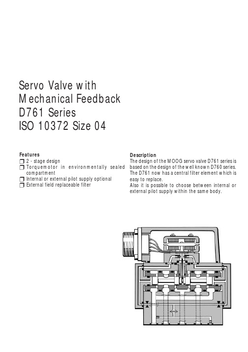
DescriptionThe design of the MOOG servo valve D761 series is based on the design of the well known D760 series.The D761 now has a central filter element which is easy to replace.Also it is possible to choose between internal or external pilot supply within the same body.Featuresr 2 - stage designr Torquemotor in environmentally sealed compartmentr Internal or external pilot supply optional r External field replaceable filterServo Valve withMechanical Feedback D761 SeriesISO 10372 Size 04Mounting pattern ISO 10372 size 04Pilot stageNozzle-flapper principle, mechanical feedback Pilot connection internal or externaloptional port XInstallation options any position, fixed or movable Mass[kg]1Rated flow(±10%) at ∆p N =35 bar per land Standard version [l/min]3,8 / 9,5 / 19 / 38 / 63High response version [l/min]3,8 / 9,5 / 19 / 38Operating pressure Ports P, A and B Standard pressure version [bar]15 to 210High pressure version [bar]315(350 on request)Return pressure Port T [bar]max. 210Temperature range Fluid and ambient [°C]-10 to +130Operating fluid Mineral oil based hydraulic fluid DIN 51524 part 1 to 3,other fluids on requestViscosity recommended [mm 2/s]15 to 45allowable [mm 2/s] 5 to 400Class of cleanliness The cleanliness of the hydraulic fluid greatly affects the performance(spool positioning, high resolution) and wear (metering edges,pressure gain, leakage) of the valverecommended for normal operation ISO 440614/11for longer life ISO 440613/10System filtration High pressure filter (without by-pass but with dirt alarm) mountedin the main flow and if possible directly upstream of the valveFilter ratingrecommended for normal operation ß10 ≥ 75 (15 µm absolute)for longer life ß5 ≥ 75 (5 µm absolute)Disc filter for first stage [µm]65 (nominal)Threshold*[%]< 0,5Hysteresis*[%]< 3%Null bias*[%]< 2%Null shift with ∆T = 55 K [%]< 2%Pressure null shift 70 % to 100 % system pressure [%]< 2%Null leakage flow imax. (~ critical lap)[l/min]< 1,5 to 2,3Pilot leakage flowi[l/min]<1Degree of protection with mounted mating connector IEC 144 class: IP 65Shipping plate Delivered with an oil sealed shipping plate under the mounting surface* measured at 210 bar pilot or operating pressure, respectively, and fluid viscosity of 32 mm 2/sD761 SeriesTechnical data Dimensions2The mounting manifold must conform to ISO 10372 size 04.Mounting surface needs to be flat within 0,02 mm. Average surface finish value, Ra, betterthan 1µm.Model-NumberType DesignationOptions may increase price.Technical changes are reserved.Ordering InformationD761 SeriesOrdering information Electrical connectionsPreferred configurations are highlighted.All combinations may not be available.Please contact MOOG.Note: Before applying electrical signals the pilot stage has to be pressurized.3Q Q p p NN=∆∆Flow - load characteristicsThe flow is dependent upon the electrical command signal and valve pressure drop. The flow for a given valve pressure drop can be calculated using the square root function for sharp edged orifices as follows:Q [l/min]=calculated flow Q N [l/min]=rated flow ∆p [bar]=actual valvepressure drop∆p N [bar]=rated valve pressuredropThe typicalcharacteristic curves for frequency response are measured at 210 bar pilot or operating pressure, respectively, and fluid viscosity of 32 mm 2/s.Standard valves:Curves a: Q N 3,8; 9,5; 19 and 38 l/minCurves b: Q N 63 l/minHigh response valves:Curves a: Q N 3,8; 9,5 and 19 l/minCurves b: Q N 38 l/minB A M / P r i n t e d i n G e r m a n yD761 SeriesCharacteristic curvesSpare parts and accessoriesFrequency response D761-E /Rev3 / 12.95MOOG Controls Limited Ashchurch Tewkesbury Gloucestershire GL20 8NATelephone (01684) 29 66 00Telefax (01684) 29 67 60MOOG GmbHHanns- Klemm-Straße 28D - 71034 Böblingen Postfach 1670D - 71006 Böblingen Telefon (07031) 622-0Telefax (07031) 622-191This catalogue is for users with technical knowledge. To ensure that all necessary characteristics for function and safety of the system are given, the user has tocheck the suitabily of the products described here.In case of doubt please contact MOOG.Our quality management system is certified in accordance with DIN EN ISO 9001.。
MOOG伺服阀D660 的中文样本

多级阀的工作原理
主阀芯的位置闭环控制是由集成电子装置来实现的。 一个电气指 令信号 ( 用来设定流量 ) 作用于集成电路位置控制器并由此来驱 动阀线圈。 位置传感器通过振荡器测出主阀芯的实际位移 (实际 值, 位移电压) 。 此信号被解调并反馈至控制器与指令信号相比较。控制器驱动先 导阀偏转从而使主阀芯产生位移,直至指令信号与反馈信号之间 的偏差为零。由此得到主滑阀的位移与指令电信号成正比。
阀的体积流量计算
阀的实际体积流量取决于阀芯位移和阀口两端节流边的压降。 在 100% 指令信号(即 +10 V DC = 100% 阀口全开)、额定压降 ∆pN = 每节流边 5 bar (75 psi) 时,阀的体积流量定义为额定流量 QN。对于非额定压降,在一个特定的指令信号下,阀的体积流量 则与阀的锐边节流口的压降的平方根成正比。 Q [l/min] = 计算出的流量 = 阀的实际压降 = 阀的额定压降
A B
1
X
Y
P T
液压机能符号: 此机能符号表示阀已加上先导级压力和电源供电以及指令信号为 零时的状态。
阀的电气控制的一般要求
供电电压为 24 V DC,最小为 18 V DC,最大为 32 V DC 最大电源消耗 阀的外接保险丝 D66X D66X 200 mA 静态 300 mA 动态 0.5 A (中速延时) 所有的信号线(包括外接的传感器连线)都需屏蔽。 屏蔽采用星形接地法接至电源地 ⊥ (0 V),且与配套插头 (EMC) 的外壳相连。 EMC:满足放射需求:EN 55011:1998+A1:1999(限制级:B) 和抗扰性:EN 61000-4-3:2002-04+A1:2002-10。 考虑了配电柜和阀之间的电压降所有导线的最小横截面 ≥ 0.75 mm2 (AWG 18)。 注:进行阀的电气连接(屏蔽、e)时,必须对各点进行有效 测量以确保各点接地电势差不会引起过大的接地电流。另请参 阅穆格技术说明 TN353。
美国穆格型号
美国MOOG电液伺服阀穆格电液伺服阀 MOOG伺服阀穆格伺服阀穆格MOOG三级伺服阀MOOG直动式伺服阀D634-319C D634-399C D634-1003 D634-1005 D634-1007 D634-1008 D634-514A D634-557 D634-394CD634-1009 D634-1010 D634-1011 D634-1012 D634-1013 D634-1014 D634-1015 D634-1016 D634-1018D634-1019 D634-1023 D634-1024 D634-1025 D634-1026 D634-1027 D634-1028 D634-1029 D634-1031D634-1032 D634-1033 D634-1034 D634-1035 D634-1036 D634-1037 D634-1040 D634-1041 D634-1042D634-1043 D634-1045 D634-1046 D634-1047 D634-1049 D634-1050 D634-1051 D634-1052 D634-1053D634-1054 D634-1055 D634-1056 D634-1057 D634-1058 D634-1059 D634-1060 D634-3001 D634-301CD634-305C D634-307C D634-308C D634-317C D634-318C D634-322C D634-324C D634-326C D634-384CD634-327C D634-330C D634-331C D634-335C D634-341C D634-345C D634-346C D634-358C D634-361CD634-362C D634-368C D634-371C D634-372C D634-373C D634-374C D634-381C D634-383C D633Z7397D634-385C D634-386C D634-387C D634-388C D634-389C D634-390C D634-391C D634-392C D633Z7383D634-396C D634-397C D634-398C D634-400C D634-402C D634-403C D634-404C D634-405C D634-1001D634-406 D634-501A D634-502A D634-503 D634-504 D634-508 D634-511 D634-512A D634-513 D634-515 D634-516A D634-517 D634-518A D634-520A D634-521 D634-524A D634-525AD634-526D634-527A D634-528A D634-529A D634-530A D634-531 D634-532 D634-533 D634-534D634-536AD634-537A D634-538A D634-539 D634-540A D634-541 D634-542A D634-543A D634-544AD634-545D634-546A D634-547 D634-548 D634-550 D634-551 D634-552 D634-553A D634-554A D634-555 D634-558 D634-559 D634-560 D634K2000C D634K2001C D634K2002C D634K2003C D634K2004C D634K2005C D634K2006C D634K2007C D634K2008C D634K2009C D634K2010C D634K2011CD634K2012C D634K2013CD634K2014C D634K2015C D634K2016C D634K2017C D634K2018C D634K2019C D634K2020D634Z1020D634Z1021 D634Z1022 D634Z1038 D634Z1044 D634Z314C D634Z351C D634Z359CY D634Z360CD634Z360CYD634Z380C D634Z395C D634Z505A D634Z509 D634Z510 D634Z549A D633E703 D633E704D633E713AD633E714A D633E7365 D633E7366 D633E7411 D633K2000B D633K2001B D633K2002BD633K2003BD633K2005B D633K2006B D633K2007B D633K2008B D633K2009B D633K2010B D633K2011BD633K2012BD633K2013B D633K2014B D633K2015B D633K2017B D633K2018B D633K2019B D633K2020BD633K2021BD633K2022B D633K2023B D633K2024B D633K2025B D633K2026B D633K2027B D633K2028BD633K2029BD633K2030B D633K2031B D633K2032B D633K2033B D633K2034B D633K2035B D633K2036BD633K2037BD633K2038B D633K2039B D633K2040B D633K2041B D633K2042B D633K2043B D633K2044BD633K2045BD633K2046B D633K2047B D633K2048B D633K2049 D633K2050 D633K2051 D633Z303B D633Z305B D633Z313BD633Z317B D633Z338B D633Z348B D633Z371B D633Z379B D633Z480B D633Z506B D633Z528B D633Z529BD633Z532B D633Z539B D633Z557B D633Z570B D633Z585B D633Z586B D633Z587B D633Z588B D633Z589BD633Z590B D633Z7309 D633Z7324 D633Z7337 D633Z7352 D633Z7353 D633Z7361 B67728-001 B67728-002B67728-003 A03665-060美国Moog伺服阀说明:美国Moog伺服阀MOOG穆格伺服阀D633,D634系列,G761-3005,G761-3004,G761-3003,G761-3002,G761-3001,J761,J072,J869,G631 G761系列伺服阀 D791三级伺服阀 D661电反馈式伺服 72系列机械反馈伺服 D633/D634直动式伺服阀功率级阀型号/先导级 MOOG机能代号 D661-4651/ C41156-421 G35JOAA6VSX2HA D661-4652/ C4 1156-421 G15JOAA6VSX2HA D661-4636/C41156-421 G60KOAA5VSX2HA D661-4469C/C41156-421 G75KOAA6VS X2HA D661-4697C/C41156-421 G15JOAA5VSX2HA D661-4033/ C41156-421 P80HAAF6VSX2-A D661-4059/C41 156-411 P80HAAF6VSX2-B D661-4444C/C41156-421 G60JOAA6VSX2HA D661-4443C/C41156-421 G45J0AA6VS X2HA D661-4506C/C41156-421 G23J0AA6VSX2HA D661-4539C/C41156-421 G35JOAA5VSX2HA MOOG型号/先导级 MOOG机能代号 D662Z4311K/D630-072A P01JXMF6VSX2-A D662-4010/D061-8411 D02HABF6VSX2-A D662Z 4336K/D630-272D P01JXMF6VSX2-A MOOG型号/先导级 MOOG机能代号 D663Z4307K/D630Z067A P02JONF6VS X2-A D663-4007/D061-8412 L03HABD6VSX2-A MOOG型号/先导级 MOOG机能代号 D663Z4307K/D630Z067A P 02JONF6VSX2-A D663-4007/D061-8412 L03HABD6VSX2-A D634-341C R40K02M0NSS2 D634-319C R40KO2M0NS P2 D633-333B R16KO1F0NSS MOOG型号/先导级 MOOG机能代号 D791-5009/D761-2612 S16J0QA6VSB0-P D7 91-4025/ S25J0PA6VSX2-A D791-4001/待查 S25J0QB6VSX2-B D791-4002/D761-2617 S25J0QB5VSX2-B D791-4028/D761-2619 S25J0QB6VSX2-B D791-4046/D761-2619 S25J0QA6VSX2-B MOOG型号 MOOG机能代号 07 2-559A S15F0FA4VBL, 072-558A S22FOFA4VBL《新型号:072-1203-10》。
Omega OM-MICROLITE 蜂鸟数据记录仪说明书
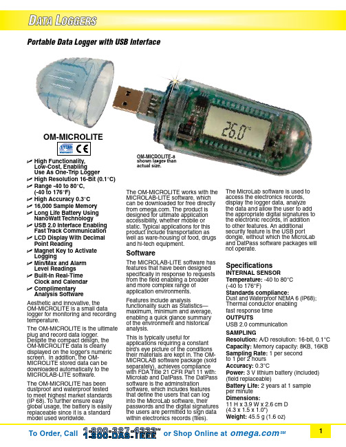
Portable Data Logger with USB InterfaceAesthetic and innovative, the OM-MICROLITE is a small data logger for monitoring and recording temperature.The OM-MICROLITE is the ultimate plug and record data logger. Despite the compact design, the OM-MICROLITE data is clearly displayed on the logger’s numeric screen. In addition, the OM-MICROLITE stored data can be downloaded automatically to the MICROLAB-LITE software.The OM-MICROLITE has been dustproof and waterproof tested to meet highest market standards (IP 68). To further ensure easy global usage, the battery is easily replaceable since it is a standard model used worldwide.U H igh Functionality, Low-Cost, Enabling Use As One-Trip LoggerU H igh Resolution 16-Bit (0.1°C)U R ange -40 to 80°C, (-40 to 176°F)U High Accuracy 0.3°CU 16,000 Sample MemoryU L ong Life Battery Using NanoWatt TechnologyUU SB 2.0 Interface Enabling Fast Track CommunicationU L CD Display With Decimal Point ReadingU M agnet Key to Activate LoggingU M in/Max and Alarm Level ReadingsU B uilt-In Real-Time Clock and CalendarU C omplimentary Analysis SoftwareOM-MICROLITE-8 shown larger than actual size.The OM-MICROLITE works with the MICROLAB-LITE software, which can be downloaded for free directly from . The product is designed for ultimate application accessibility, whether mobile or static. Typical applications for this product include transportation as well as ware-housing of food, drugs and hi-tech equipment.Software The MICROLAB-LITE software has features that have been designed specifically in response to requests from the field enabling a broader and more complex range of application environments. Features include analysis functionality such as Statistics—maximum, minimum and average, enabling a quick glance summary of the environment and historical analysis. This is typically useful for applications requiring a constant bird’s eye picture of the conditions their materials are kept in. The OM-MICROLAB software package (sold separately), achieves compliance with FDA Title 21 CFR Part 11 with: Microlab and DatPass. The DatPass software is the adminstration software, which includes features that define the users that can log into the MicroLab software, their passwords and the digital signatures the users are permitted to sign data within electronics records (files). The MicroLab software is used to access the electronics records, display the logger data, analyze the data and allow the user to add the appropriate digital signatures to the electronic records, in addition to other features. An additional security feature is the USB port dongle, without which the MicroLab and DatPass software packages will not operate.SpecificationsINTERNAL SENSOR Temperature: -40 to 80°C (-40 to 176°F)Standards compliance: Dust and Waterproof NEMA 6 (IP68); Thermal conductor enabling fast response time OUTPUTS USB 2.0 communication SAMPLINg Resolution: A/D resolution: 16-bit, 0.1°C Capacity: Memory capacity: 8KB, 16KB Sampling Rate: 1 per second to 1 per 2 hours Accuracy: 0.3°C Power: 3 V lithium battery (included) (field replaceable)Battery Life: 2 years at 1 sample per minute Dimensions: 11 H x 3.9 W x 2.6 cm D (4.3 x 1.5 x 1.0")Weight: 45.5 g (1.6 oz)Ordering Example: OM-MICROLITE-8, portable data logger with USB interface.OM-MICROLITE-8 with laptop (laptop not included)The MICROLAB-LITE software displays data in graphical or tabular formatDisplay: LCD with decimal point; Visual Alert—Alarm icon when crossing predefined thresholds, low battery indicationOperation: Data scroll on the LCD, reed switch to start measuringSoftware: Windows ® 2000/ME/XP/NT 4.0 or higher and Vista (Also available—OM-MICROLAB 21 CFR Part 11 Standards Compliance Software)OM-MICROLITE-8 shown actual size.。
穆格电动运动系统

Utah
・Salt Lake City
New York State
・Buffalo
California
・Torrance
・Chatsworth
America
Pacific
Brazil
Australia
Brazil
Australia 10
Moog proprietary and/or confidential data
荷兰穆格分部
•成立于1979年 •现有员工160人 •2005年并入穆格公司 •位于荷兰阿姆斯特丹 •专注提供仿真产品的研发 和制造
13 Moog proprietary and/or confidential data
穆格FCS产品
提供高性能的控制系统解决方案,产品主要针对三个主要市场:
仿真/模拟器
Moog FCS产品在中国
-1993年进入中国市场;
-已经有超过50套系统销售记录;
-客户对产品的性能和服务表示满 意;
-主要市场:仿真/模拟器、测试;
-所有产品出口到中国没有任何的 产品限制;
Moog’s high performance actuation products control military and Commercial aircraft, satellites and space vehicles, launch vehicles, Missiles, and automated industrial machinery.
航空测试
汽车测试
波音 阿帕奇直升机模拟器
台风战斗机的全机试验,英国 BAE系统公司
德国大众汽车公司,帕萨特汽车的悬挂系 统测试
moog伺服阀中文样本
moog伺服阀中文样本一、IntroductionMoog伺服阀是一款高性能的机电一体化控制系统,可以应用于多种工业领域,如航空、汽车、石油等。
其独特的设计原理和使用方法使其在市场上备受青睐。
本文将介绍Moog伺服阀的中文样本,包括其规格、性能和应用领域等方面。
二、Moog伺服阀中文样本的规格Moog伺服阀中文样本的规格主要包括其工作压力、流量和工作温度等参数。
其中,其工作压力范围为0-210bar,流量范围为0-60L/min,其工作温度范围为-20℃至+60℃。
此外,Moog伺服阀中文样本的接口类型也有多种选择,如NG6、NG10等。
三、Moog伺服阀中文样本的性能Moog伺服阀中文样本具有很高的性能,这得益于其先进的设计原理和制造工艺。
其主要性能表现为以下几点:1.精准的控制能力:Moog伺服阀可以实现高精度的动作控制,满足对运动要求较高的工业领域的应用需求。
2.快速的响应速度:Moog伺服阀的响应速度非常快,可以在微秒级别内实现动态调整,提高了运动的平滑度和精度。
3.稳定的工作性能:Moog伺服阀可以在复杂的工作环境下稳定运行,具有出色的抗干扰能力和长时间稳定性。
4.出色的耐用性:Moog伺服阀采用优质材料和制造工艺,经得住复杂的工业环境和恶劣的气候条件的考验,具有出色的耐用性。
四、Moog伺服阀中文样本的应用领域Moog伺服阀中文样本可以应用于多个工业领域,如航空、汽车、石油、化工、制造等领域。
其在这些领域的应用主要体现在以下几个方面:1.操控系统:Moog伺服阀可以实现精准的操控系统,如自动化生产线、军事装备等。
2.机电一体化控制系统:Moog伺服阀可以控制伺服电机的运动,从而实现高效的机电一体化控制系统。
3.流量控制:Moog伺服阀可以控制流量,常用于污水处理、火力发电等领域。
4.液压系统:Moog伺服阀可以控制液压系统的运动,如挖掘机、叉车、起重机等。
五、结论Moog伺服阀中文样本是一款高性能的机电一体化控制系统,具有精准的控制能力、快速的响应速度、稳定的工作性能和出色的耐用性等特点。
D661valves-(moog伺服阀样本)
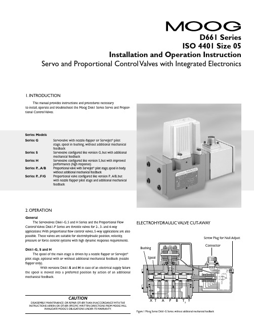
CAUTIONDISASSEMBLY, MAINTENANCE, OR REPAIR OTHER THAN IN ACCORDANCE WITH THE INSTRUCTIONS HEREIN OR OTHER SPECIFIC WRITTEN DIRECTIONS FROM MOOG WILLINVALIDATE MOOG’S OBLIGATIONS UNDER ITS WARRANTY .D661 Series ISO 4401 Size 05Installation and Operation InstructionServo and Proportional Control Valves with Integrated Electronics1. INTRODUCTIONThis manual provides instructions and procedures necessaryto install, operate and troubleshoot the Moog D661 Series Servo and Propor-tional Control Valves.2. OPERATIONGeneralThe Servovalves D661-G, S and H Series and the Proportional Flow Control Valves D661-P Series are throttle valves for 2-, 3- and 4-wayapplications. With proportional flow control valves, 5-way applications are also possible. These valves are suitable for electrohydraulic position, velocitiy,pressure or force control systems with high dynamic response requirements.D661-G, S and HThe spool of the main stage is driven by a nozzle flapper or ServoJet ®pilot stage, optional with or without additional mechanical feedback (nozzle flapper only).With versions D661-S and H in case of an electrical supply failurethe spool is moved into a preferred position by action of an additional mechanical feedback.E LE CTROHYDRAULIC VALVE CUT -AWAYFigure 1 Moog Series D661-G Series, without additional mechanical feedbackX T A P BT 2YConnectorSpoolBushingScrew Plug for Null AdjustSeries Models Series GServovalve with nozzle-flapper or ServoJet ® pilot stage, spool in bushing, without additional mechanical feedbackSeries S Servovalve configured like version G, but with additional mechanical feedbackSeries H Servovalve configured like version S, but with improved performance (high response)Series P ...A/B Proportional valve with ServoJet ® pilot stage, spool in body ,without additional mechanical feedbackSeries P ...F/GProportional valve configured like version P ...A/B, but with nozzle flapper pilot stage and additional mechanical feedbackJet pipe Annular areaNozzleReceiver2Operating Principle of the T wo-Stage ValveAn electric input signal (flow rate command) is applied to the integrated control amplifier which drives a current through the coils of the pilot stage torque motor. Thus the deflected nozzle-flapper system produces a pressure difference across the drive areas of the spool and effects its movement. The position transducer which is excited via an oscillator measures the position of the spool (actual value, position voltage).This signal is then rectified by a demodulator and is fed back to the control amplifier where it is compared with the command signal. The control amplifier drives the torque motor until command voltage and feedback voltage are equal.Thus, the position of the spool is proportional to the electric command signal.Proportional Flow Control Valve D661-...PThe nozzle flapper design of the pilot stage has been converted into an improved version with jet pipe amplifier (ServoJet ®).The ServoJet ® pilot stage consists mainly of torque motor, jet pipe and receiver.A current through the coil displaces the jet pipe from neutral. This displacement combined with the special shape of the nozzle directs a focussed fluid jet more into one receiver bore than into the other.The jet now produces a pressure difference in the control ports. This pressure difference results in a pilot flow, which in turn causes a spool displacement. The pilot stage drain is through the annular area around the nozzle to tank.Operating Principle of the T wo-Stage ValveAn electric input signal (flow rate command) is applied to the integrated control amplifier which drives a current through the coil of the pilot stage torque motor. The thus deflected jet pipe produces a pressure difference across the drive areas of the spool and effects its movement.The position transducer which is excited via an oscillator measures the position of the spool (actual value, position voltage). This signal is then demodulated and fed back to the controller where it is compared with the command signal. The controller drives the torque motor until the error between command signal and feedback signal is zero. Thus the position of the spool is proportional to the electric command signal.Failsafe Version D661-...PFor applications with proportional control valves where certain safety regulations are applicable, a defined metering spool position is needed in order to avoid potential damage. Therefore, failsafe versions are offered as an option for the MOOG proportional valves.After external triggering, this failsafe function causes a defined metering spool position.Mechanical Failsafe version (biased pilot stage with mechanical feedback)The safe position of the spool will be obtained after cut off of pilot pressure supply (external pilot connection) or operating pressure supply D661-P ...A/BWD661-P ...A/BU Proportional Valve D661-P ...A/BWand D661-P ...A/BU Series with electrically operated failsafe functionProportional Valve D661-P ...AP Serieswith electrically operated failsafe function2- stage Proportional Valve D661-...P ...A/B SeriesServovalve D661 - ...S and H Series with additional mechanical feedback3Electric characteristics of the 2/2-way solenoid valveFunctionelectro magnetic Nominal voltage 24 VDC Nominal power12 WDIN 43650-1Form A: 2+PE-PG9With failsafe versions R and L, a defined spool position is reached when the electric supply to the valve electronics is switched offwhile the pilot pressure is still applied. With version M, the resulting spool position is undefined.Electrically operated failsafe versionThe safe position of the spool will be obtained after switching off the integrated 2/2-way solenoid seat valve.With failsafe versions W , U and G, after cut-off of the solenoid, the spool moves to midposition. When the electric supply to the valveelectronics is switched off while the pilot pressure is still effective and the solenoid is still switched on, the spool will move to a defined end position with versions U and G.With failsafe version P , the integrated seat valve will shut off the external pilot pressure after switching off the solenoid.Cutting off the 24 VDC supply to the solenoid operated 2/2-way seat valveo protect relay contacts or semiconductors against damage, a Zener diode is required1)With version P at 210 bar pilot or operating pressure,with versions G ,S and H at 140 bar pilot or operating pressure,fluid viscosity of 32 mm˝/s and fluid temperature of 40°C.2)For long life wear protection of metering landsFor additional technical information such as dimensions, ordering information, etc., see the D660 series catalog.T echnical DataInternal/External Pilot Connection a.Conversion for operation with internal or external pilot connection.The pilot connection mode as shipped is indicated by the respective code letter of the type designation on the nameplate.With the 5-way version, where the T and T 2 ports are interchangedwith the P port, pilot supply port X and return portY must be connected externally.43. SAFETY INSTRUCTIONSWarnings and Symbols a.Refers to special orders and prohibitions to prevent damage b.Refers to special orders and prohibitions to prevent injury or extensive damageCorrect Application a.The D661 Series Valves are control valves suited for electrohydraulicposition, velocity, pressure and force control.b.The valves are designed for flow control in hydraulic systems thatoperate with mineral oil based fluids. Others upon ing the valves for purposes other than those mentioned above isconsidered contrary to the intended use. The user bears entirely the risk of such misuse.d.Correct application involves also observing the operating instruction andcomplying with the inspection and maintenance directives.Organizational Measures a.We recommend including this operating instruction into themaintenance plan of the machine/plant.b.In addition to the operating instruction, observe also all other generallyapplicable legal and other mandatory regulations relevant to accident prevention and environmental protection. Instruct the operator accordingly.c.All safety and danger prevention instructions of the machine/plant mustmeet the requirements of EN 982.Selection and Qualification of Personnel a.Only well-trained and instructed personnel are allowed to work with Moogcontrol valves.b.Work with electrohydraulic valves must be carried out only by personnelhaving special knowledge and experience in plants running with electrohydraulic controls.Safety Instructions for Specific Operational Phases a.T ake the necessary precautions to ensure that the machine/plant isused only when in a safe and reliable state.b.Check the machine/plant at least once per working shift for obviousdamage and defects (i.e. leakage). Report any changes to the responsible group/person immediately. If necessary, stop the machine immediately and secure it.c.In the event of malfunctions, stop the machine/plant immediately andd.If the machine/plant is completely shut down for maintenance and repairwork at the valve, it must be secured against inadvertent start up by:➢ Locking the principal control elements and removing the key.➢ Attaching a warning sign to the main switch.Safety Instructions for the Operation of Hydraulic Plantsa.Work on electrohydraulic equipment must be carried out only by personnelb.Check all lines, hoses and fittings of the plant regularly for leaks andobvious damage. Repair damage immediately.c.Before removing the valve, depressurize all system sections to beopened, pressure lines and accumulators of the hydraulic system in accordance with the specific instructions for the plant.d.When handling oil, grease and other chemical substances, observe safetyregulations valid for each product.4. INSTALLATIONGeneral Information pare model number and valve type with information from thehydraulic schematic or bill of material.b.The valve can be mounted in any direction, fixed or moving.c.Check mounting surface flatness (0.02 mm for 100 mm) andsurface finish (Ra <1 µm)d.Pay attention to cleanliness of mounting surface and surroundings wheninstalling the e lint-free tissue to clean!f.Before installation, remove shipping plate from the valve and save itfor later use.g.Pay attention to correct position of ports and location of o-rings duringe M6 x 60 socket head bolts according to DIN 912 for mounting,strength class 10.9 or 12.9, and cross torque to 13 Nm (tolerance ±10 %)Electric Null adjust(behind screw plug)Set screw 4M4 x 6Set screw 1M4 x 6Set screw 2M4 x 6Set screw 3M4 x 6X 1)P YFilterServovalve D661 Gwithout mechanical feedbackand Proportional Valve D661 P ...A/BPilot Flow Set Screw M4 x 6Supply bore 1bore 2Internal P closed open External X openclosedPilot Flow Set Screw M4 x 6Return bore 3bore 4Internal T closed open E xternal Yopenclosed b.Conversion instruction for Servovalves D661-G and Proportionalvalves D661-P ...A/B1) Check for sufficient length (100 mm) of mounting surface!...P ...A/BD661-...P 5c.Conversion instruction for Servovalves D661-S, H and P ...F/G screw plugM4 x 8 DIN 6912-8.8with metal sealring U4,5-7-1FilterElectric Nulladjust(behind screw plug)X PPilot Flow Screw Plug Supply In PortInternal P X External XP5. SETTING UPThis information is valid for new installations to be put into operation as well as for repair cases.Filling the Hydraulic SystemNew oil is never clean. Therefore, the system should generally be filled by using a filling filter .This fine mesh filter should at least complywith the following requirement: ß10 ≈ 75 (10 µm absolute).Flushing the Hydraulic SystemBefore the hydraulic system is put into operation for the first time (also after modifications), it has to be flushed carefullyaccording to the instructions of the manufacturer of the plant / machine.a.Before flushing, suitable flushing elements have to be inserted in the pressure filters instead of the high pressure elements.b.Before flushing, the operational temperature of the hydraulic system should be achieved. Observe temperature!c.A flushing plate or, if the system allows, a directional valve should be mounted in place of the Moog porportional valve. The P- and T-connections are flushed through the flushing plate. The user A- and B-Attention: The directional valve can lead to unpermissablemovements in the load (i.e. with parallel drives), which may result in damage of the plant / machine. Instructions of the manufacturer have to be strictly observed.Minimum flushing time t can be calculated as follows:d.The flushing process can be considered completed when a system cleanliness of 15/12 according to ISO 4406 or 6 according to NAS1638 or better is achieved. A long life of the metering lands of the proportional valve can be expected for this cleanliness class.V = content of reservoir [gallons]Q = flow rate of the pump [gpm]t = V • 5Qe.Replace flushing elements in the pressure filters by suitable high pressure elements after flushing. Install Moog proportional valve instead of flushing plate or directional valve.Setting Up a.Set up machine/plant according to the operation instructions of the manufacturer after the valves have been installed. Vent hydraulic system!b.The safety instructions of the machine/plant manufacturer must be observed. Especially the safety requirements for machines like injection molding machines (EN 201), blow molding machines (EN 422) and die casting machines (EN 869), to name a few, are important.c.Observe oil temperature.d.Check hydraulic system for external leakage!6. MAINTENANCEBesides regular visual inspection for external leakage and filter replacement, maintenance work at the D661 Series valves is not required.Explosion proof valves D661K... must not be opened by the customer! Unauthorized opening will invalidate the explosion proof approval! Return failed valve to the factory.Moog valves can only be repaired at Moog Service Centers (for addresses see back page of this operation instructions).Filter ReplacementThe built-in filter disk protects orifices and nozzles against coarse contaminants. W ith severe contamination, the valve response will be reduced.Replace filter!Cleaning the filter is useless and may be dangerous!Before starting to work on the valve, clean the external surface around the filter cover!Attention: The filter disk (21) flows from inside to the outside.After removal of the cover (20) any contamination particles are on the insideof the disk (21) and therefore, cannot be seen from outside.a.Remove four internal hex bolts (38) using A llen wrench (3 mm). Removecover (20). Remove the filter disk (21) now accessible by using a scriber or a fine screwdriver as extraction tool.b.(53) for damage.Replace if necessary.c.Insert o-ring (53) first. Then insert the new filter disk (21) such that the side with the notch at the rim points outward. Mount o-ring (59) on the cover (20) using clean grease, and mount cover to the valve body.T orque the four bolts (38) to 4 Nm (35 in-lb).d.Check valve for external leakage after pressurizing it.ELECTRONICS INFORMATIONValve connectorsPossible connectors Please note information regarding input signals on the nameplate!Valve electronics with supply voltage ± 15 VDC and 6+PE pole connector Number Supply Voltageof Pins ± 15 VDC 24 VDC6 + PE X X 11 + PE–X 11 + 1 (PE) Bayonet X –6 (old, without PE)X –12 (old, without PE) BayonetX–a.Command inputCommand signal 0 to ±10 VThe spool stroke of the valve is proportional to (U D – U E ). 100% valve opening P ➔ A and B ➔ T is achieved at (U D –U E ) = +10 V . At 0 V command the spool is in the center position.The input stage is a differential amplifier. If only one command signal isavailable, pin D or E is connected to signal ground (pin C) according to the required operating direction (to be done at the mating connector).Command signal 0 to ±10 mAThe spool stroke of the valve is proportional to (I D –I E ).100% valve opening P ➔A and B ➔T is achieved at (I D –I E )= +10 mA. At 0 mA command the spool is in the center position.Either pin D or E is used according to the required operating direction. T he unused pin is left open (not connected at the mating connector). The input pins D and E are inverting.b.Monitoring outputActual value 0 to ±10 VThe actual spool position value can be measured at pin F . This signal can be used for monitoring and fault detection purposes.The spool stroke range corresponds to ±10 V . +10 V corresponds to 100% valve opening P ➔ A and B ➔ T .Actual value 0 to ±10 mAThe actual spool position value can be measured at pin F . This signal can be used for monitoring and fault detection purposes.The spool stroke range corresponds to ±10 mA. +10 mA corresponds to 100% valve opening P ➔ A and B ➔ T .Connector Wiring - T ype code S (see sticker on the electronics housing)6Valve electronics with supply voltage ± 15 VDC and 11+1 pole bayonet connectorAlternate connector for certain valve models a.Command inputCommand signal 0 to ±10 VThe spool stroke of the valve is proportional to (U D – U E ). 100% valve opening P ➔ A and B ➔ T is achieved at (U D –U E ) = +10 V . At 0 V command the spool is in the center position.The input stage is a differential amplifier. If only one command signal is available, pin D or E is connected to signal ground (pin C) according to the required operating direction (to be done at the mating connector).Command signal 0 to ±10 mAThe spool stroke of the valve is proportional to (I D – I E ).100% valve opening P ➔ A and B ➔ T is achieved at (I D – I E ) = +10 mA. At 0 mA command the spool is in the center position. Either pin D or E is used according to the required operating direction. T he unused pin is left open (not connected at the mating connector). The input pins D and E are inverting.Command signal 4 to 20 mAThe spool stroke of the valve is proportional (I D –12 mA). 100% valve opeming P ➔ A and B ➔ T at I D = 20 mA. At 12mA command the spool is in the center position.The unused Pin E is left open (not connected in the mating connector).b.Monitoring outputThe actual spool position value can be measured at pin F .This signal can be used for monitoring and fault detection mand signal 0 to ±10 VThe spool stroke range corresponds to ±10 V .+10 V corresponds to 100% valve opening P ➔ A and B ➔ T .Command signal 0 to ±10 mAThe spool stroke range corresponds to ±10 mA.+10 mA corresponds to 100% valve opening P ➔ A and B ➔ T .Command signal 4 to 20 mAThe spool stroke range corresponds to 4 to 20 mA.20 mA corresponds to 100% valve opening P ➔ A and B ➔T .Please note "General Requirements" on page 6.Connector Wiring - T ype code V (see sticker on the electronics housing)7Connector Wiring - Type code 6Valve electronics with supply voltage ± 15 V DC and 6 pole connector (without protective grounding)a.Command inputCommand signal 0 to ±10 VThe spool stroke of the valve is proportional to (U D – U E ). 100% valve opening P ➔ A and B ➔ T is achieved at (U D –U E ) = +10 V . At 0 V command the spool is in the center position.The input stage is a differential amplifier. If only one command signal isavailable, pin D or E is connected to signal ground (pin C) according to the required operating direction (to be done at the mating connector).Command signal 0 to ±10 mAThe spool stroke of the valve is proportional to (I D – I E ).100% valve opening P ➔ A and B ➔ T is achieved at (I D – I E )= +10 mA. At 0 mA command the spool is in the center position.Either pin D or E is used according to the required operating direction. T he unused pin is left open (not connected at the mating connector). The input pins D and E are inverting.Command signal 4 to 20 mAThe spool stroke of the valve is proportional (I D –12 mA). 100% valve opeming P ➔ A and B ➔ T at I D = 20 mA.At 12mA command the spool is in the center position.The unused Pin E is left open (not connected in the mating connector).b.Monitoring outputThe actual spool position value can be measured at pin F.This signal can be used for monitoring and fault detection mand signal 0 to ±10 VThe spool stroke range corresponds to ±10 V .+10 V corresponds to 100% valve opening P ➔ A and B ➔ T .Command signal 0 to ±10 mAThe spool stroke range corresponds to ±10 mA.+10 mA corresponds to 100% valve opening P ➔ A and B ➔ mand signal 4 to 20 mAThe spool stroke range corresponds to 4 to 20 mA.20 mA corresponds to 100% valve opening P ➔ A and B ➔ T.8Valve electronics with supply voltage ± 15 V DC and 12 pole bayonet connector (without protective grounding)a.Command inputCommand signal 0 to ±10 VThe spool stroke of the valve is proportional to (U D – U E ). 100% valve opening P ➔ A and B ➔ T is achieved at (U D –U E ) = +10 V . At 0 V command the spool is in the center position.The input stage is a differential amplifier. If only one command signal isb.Monitoring outputThe actual spool position value can be measured at pin F .This signal can be used for monitoring and fault detection mand signal 0 to ±10 VThe spool stroke range corresponds to ±10 V .+10 V corresponds to 100% valve opening P ➔ A and B ➔ T .Command signal 0 to ±10 mA9Valve electronics with supply voltage 24 Volt and 6+PE - pole connector a.Command inputCommand signal 0 to ±10 VThe spool stroke of the valve is proportional to (U D – U E ). 100% valve opening P ➔ A and B ➔ T is achieved at (U D –U E ) = +10 V.At 0 V command the spool is in the center position.The input stage is a differential amplifier. If only one command signal is available, pin D or E is connected to signal ground (pin B) according to the required operating direction (to be done at the mating connector).Command signal 0 to ±10 mAThe spool stroke of the valve is proportional to (I D – I E ). 100% valve opening P ➔ A and B ➔ T is achieved at (I D – I E ) = +10 mA. At 0 mA command the spool is in the center position.Either pin D or E is used according to the required operating direction.The unused pin is left open (not connected at the mating connector).The input pins D and E are inverting.b.Monitoring outputActual value +2,5 to +13,5 VValves with voltage and current command inputThe actual spool position value can be measured at pin F (see diagram below). This signal can be used for monitoring and fault detection purposes.The spool stroke range corresponds to +2,5 to +13,5 V . The center position is at +8 V . +13,5 V corresponds to 100% valve opening P ➔ A and B ➔ T.10Valve electronics with supply voltage 24 V olt and 11+PE - pole connector a.Command inputCommand signal 0 to ±10 VThe spool stroke of the valve is proportional to (U D – U E ). 100% valve opening P ➔ A and B ➔ T is achieved at (U D –U E ) = +10 V . At 0 V command the spool is in the center position.The input stage is a differential amplifier. If only one command signal isavailable, pin D or E is connected to signal ground (pin B) according to the required operating direction (to be done at the mating connector).Command signal 0 to ±10 mAThe spool stroke of the valve is proportional to (I D – I E ). 100% valve opening P ➔A and B ➔ T is achieved at (I D – I E ) = +10 mA. At 0 mA command the spool is in the center position.Either pin D or E is used according to the required operating direction.The unused pin is left open (not connected at the mating connector). The input pins D and E are inverting.b.Monitoring outputActual value 0 to ±10 VValves with voltage and current command inputThe actual value, i. e. the spool position, can be measured between pins 6 and 7. This signal can be used for monitoring and fault detection purposes. The signal can only be measured using a weighted differential amplifier (see dia-gram below) or a voltmeter with an input impedance greater than 1M Ω. T he spool stroke range corresponds to ±10 V . The centered position is at 0 V .+10 V corresponds to 100% valve opening P ➔ A and B ➔ T .If the actual value will be used with a machine control system, the differential input circuit must be used. Another option is to use the aforementioned circuit for the 6+PE pole connector. Pin 6 according to DIN 43 651corresponds to pin F according to DIN 43 563 (see diagram page 12).Circuit diagram for measurement of actual value U 6-7 (position of main spool) for valves with 11+PE pole connectorConnector Wiring - Type code letter E (see sticker on the electronics housing)Please note "General Requirements" on page 10.118. TOOLS AND EQUIPMENTa.5mm Allen wrenchb.3mm Allen wrenchrge blade screwdriverd.Small screwdrivere.Scriber or small screwdriverf.Clean grease (mounting and insertion of O-rings)The D661 Series valves require tools for installation, set up, null adjustment and filter replacement.➢ Installation of the valve➢ Mounting of the D661 Series requires 5mm Allen wrench ➢ Null adjust of the valve at set up➢ Large blade screwdriver to remove the cover screw(see cut-away diagram on page 1)➢ Small screwdriver for zero setting on internal potentiometerReplacement PartsPart Description D661-Qty.Part Number O-Ring, ports P , T , A, B, (T 2)all 542082-004O-Ring, ports X&Y all 242082-011Replaceable Filter Disk P ...A/B 1A67999 200Replaceable Filter Disk G, S, H & P ...F/G 1A67999 100O-Ring, behind filter disk all 1A25163 013 015O-Ring, for filter cover P ...A/B1B97009 080O-Ring, for filter coverG, S, H 1A25163 017 020Allen Setscrew, ports X & Y G & P 266166 040 006Screw plug, port X S & H 166098 040 006Seal, port X S & H1A25528 040Accessories (not part of the valve delivery)Part DescriptionD661-Qty.Part NumberMating Connector ,waterproof, protection IP65 6+PE-pole DIN 43563B97007 061 11+PE-poleDIN 43651B97024 111 11+1-pole (Bayonet)MIL C-26482/14-12B97027 012 6-poleMIL C-5015/14S-6A26201 004 12-pole (Bayonet)MIL C-26482/14-12B97027 012Mounting Manifolds See special data sheet Mounting BoltsM6x60 DIN 912-10.9...G and ...P 4A03665-060-060 M6x55 DIN 912-10.9...H and ...S4A03665-060-055Flushing PlateB67728-001Flushing Plate B67728-002Flushing PlateB67728-003127. ELECTRICAL NULL ADJUSTMENTThe hydraulic null of the valve is preset at the factory with a tolerance of ± 2% of rated signal. If necessary, this null can be readjusted by the user of the valve.a.null! Contact machine/plant manufacturer.b.Procedure: Remove the command signal to the valve only by disconnecting command signal lead at the cabinet.Remove cover screw on electronics housing to access the null adjust potentiometer. Use a small screwdriver (blade width 2.5 mm) to turn the potentiometer screw either clockwise or counterclockwise. Usually it will not be necessary to turn the screw more than 2 turns in either direction (± 1 turn is equivalent to ± 15% null shift).c.While adjusting, watch the actuator (motor) motion to find the null position. With overlapped valves, turn the null adjust screw carefully in both directions to just start motion and then back into deadzone midposition between those two screw positions.d.After proper null adjustment, reconnect the command signal lead and install protective cover screw again.。
OMEGA 电子测量仪器产品说明书
It is the policy of OMEGA to comply with all worldwide safety and EMC/EMI regulations that apply. OMEGA is constantly pursuing certification of its products to the European New Approach Directives. OMEGA will add the CE mark to every appropriate device upon certification.The information contained in this document is believed to be correct, but OMEGA Engineering, Inc. accepts no liability for any errors it contains,and reserves the right to alter specifications without notice.W ARNING: These products are not designed for use in, and should not be used for , patient-connected applications.Benelux:Postbus 8034, 1180 LA Amstelveen The NetherlandsTEL: +31 (0)20 6418405 FAX: +31 (0)20 6434643Toll Free in Benelux: 0800 0993344e-mail:************Czech Republic:Rude ´arma ´d y 1868, 733 01 Karvina´ 8TEL: +420 (0)69 6311899FAX: +420 (0)69 6311114Toll Free in Czech Republic: 0800-1-66342e-mail:***************France:9, rue Denis Papin, 78190 TrappesTEL: +33 (0)130 621 400 FAX: +33 (0)130 699 120TollFreeinFrance:0800-4-06342e-mail:****************Servicing Europe:USA and Canada:Sales Service:1-800-826-6342/ 1-800-TC-OMEGA ®Customer Service:1-800-622-2378/ 1-800-622-BEST ®Engineering Service:1-800-872-9436/ 1-800-USA-WHEN ® TELEX:996404 EASYLINK:62968934 CABLE:OMEGA USA: ISO 9001 CertifiedOne Omega Drive,P .O.Box 4047Stamford CT 06907-0047TEL:(203) 359-1660FAX:(203) 359-7700e-mail:**************Servicing North America:For immediate technical or application assistance:Mexico:TEL:(001) 800-826-6342FAX:(001) 203-359-7807En Espan ~ol:(001) 203-359-7803e-mail:*******************************.mxGermany/Austria:Daimlerstrasse 26,D-75392 Deckenpfronn,Germany TEL:+49 (0)7056 3017 FAX:+49 (0)7056 8540Toll Free in Germany:0800 TC-OMEGA SM e-mail:*****************United Kingdom: ISO 9002 Certified One Omega Drive River Bend Technology Centre Northbank,Irlam Manchester M44 5EX United Kingdom TEL:+44 (0)161 777 6611 FAX:+44 (0)161 7776622Toll Free in United Kingdom:0800488488e-mail:**************.ukCanada:976 Bergar Laval (Quebec) H7L 5A1TEL:(514) 856-6928FAX:(514) 856-6886e-mail:*************SCR POWER CONTROLLERSTABLE OF CONTENTSGeneral Descriptionand Specifications (1)Firing Modes (2)Installation and Wiring (4)Operation (9)T roubleshooting (15)Parts Lists andOrdering Codes (18)OPERATING INSTRUCTIONSSeries 19 and 39 SCR Power ControllersSeries 91 and 93 SCR Power ControllersSection 1. General DescriptionIntroductionSCR Power Controllers are designed to regulate ac power to electrical heating processes, such as ovens, furnaces, heat sealers, etc. (Note: They are not designed to drive transformers, coils or other inductive-type loads.)The controller accepts an input signal, such as 4-20 mAdc from some signal conditioning device, e.g., a temperature controller. For most processes, the combination of a temperature controller and SCR power controller will provide very accurate, automatic temperature control. For manual operation, a manual control option with a remote potentiometer is available.General SpecificationsInputs:4-20 mAdc standard, or as ordered (seeserial number) minimum voltagerequirements 10 Vdc; all inputselectrically isolated via optical couplingSupply Voltage:110/120; 208/240; 440/480, 575/600Vac, or as ordered (Phase connectionnot critical on 3-phase units)Frequency:50/60 HzAmbient T emperature:30o to 122o F for listed power ratings Cooling:ConvectionProtection:Sub-cycle, current-limiting fuse; transientvoltage suppresionLoad Resistive, 1- or 3-phase - 3-wire Wye or Delta All specifications subject to change.1234567Figure 4a. Wiring scheme for Series 19Z.Figure 4b. Wiring scheme for Series 39Z.3.21 Zero-Cross Zero-cross mode power controllers may only be used with constant resistance heating elements, such as Nichrome. They are NOT intended for high-inrush loads. Depending on the type of element used, you can oversize the load controller.3.22 Phase-AnglePhase-Angle fired power controllers may be used with high-inrush loads if the "soft-start" option is installed.Figure 5a. Wiring scheme for Series 19P.Figure 5b. Wiring scheme for Series 39P .Section 4. OperationSeries19/394.1 Series 19Z/39ZThe Series 19Z and 39Z power controllers are designed to control ac power to electrical heating processes, such as ovens, furnaces, heat sealers, etc. (Note:They are NOT intended to drive transformer coupled or inductive loads.) The controllers consist of power semiconductors (SCRs), properly sized heat sinks, and trigger circuitry. These controllers accept a control signal (e.g., 4-20 mAdc) from a signal conditioning device, such as a temperature controller. The “Z” suffix designates the controller as operating in the Zero Cross, Zero Voltage Switched, or Zero Burst firing mode.A patented trigger circuit turns on the SCRs as close as possible to the point at which the ac sine wave crosses through zero. In effect, this turns the line voltage on and off in full cycles. With an input of 4-20 mA , the output will be FULL OFF below 4 mA and FULL ON at 20 mA. Proportioning action is obtained by varying the number of cycles ON to the number of cycles OFF. The resulting output power is integrated by the heaters to produce smoothly proportional heating that varies directly with the input signal.4.2 Series 19P/39PThe Series 19P and 39P power controllers are designed to control ac power to electrical heating processes, such as ovens, furnaces, heat sealers, etc. (Note: They are NOT designed to drive transformer-coupled loads.) The controllers consist of power semiconductors (SCRs), properly sized heat sinks, and trigger circuitry.These controllers accept a control signal (e.g., 4-20 mAdc) from a signal conditioning device, such as a temperature controller.The “P” Suffix designates the controller as operating in the Phase-Angle firing mode. Providing full proportional control, SCRs are turned ON during each 1/2 cycle at apoint (phase angle) of the ac sine wave, remaining ON for the rest of the1/2 cycle. By varying the phase angle setting, the amount of voltage reaching the load may be adjusted. The output voltage is proportional to the input signal. At 4 mA input, no voltage will be applied to the load; at 20 mA input, the output voltage will almost equal the line voltage.4.3 Voltage Limit Option (Phase-Angle Fired Units Only)The output voltage of the controller can be limited by adjusting the trimmer on the printed circuit board. Turning the adjustment clockwise will increase the out put voltage limit. This control will operate over a range of about 20% to full output. Ordinarily, this adjustment is used to protect heaters that cannot operate on full line voltage, or to limit the maximum heating of a process.4.4 Soft Start Option (Phase-Angle Fired Units Only)The soft start circuitry is used to slowly turn on the voltage from the controller to the load. It is used to protect the controller when it is operating into loads having high-current, turn-on characteristics, e.g., quartz or tungsten heaters. The output voltage will rise from zero to full output over various times, depending on the time option selected.The soft start circuit presents an initial high impedance which is inserted between the signal source and the controller. This impedance decreases in value with time. Soft start action can be seen as the input signal slowly changes from 4-20 mA when full output is required.4.8 TroubleshootingIf the power controller is not functioning properly, refer to these troubleshooting procedures.Symptom:No heat or reduced heat output.Possible Cause(s)Action1. Loss of line voltage.Check powersupply.2. Line fuse or controller fuse blown.Check heater forshort circuit andcorrect problem.3. No input signal.Check signalconditioner.4. Malfunction on trigger board.Consult factory.5. Open SCR Consult factory.Troubleshooting Flowchart Symptom: Heaters will not turn off.Section 6. Model Identification Ordering Codes:Series 19/39NOTESOMEGA’s policy is to make running changes,not model changes,whenever an improvement is possible.This affords our customers the latest in technology and engineering.OMEGA is a registered trademark of OMEGA ENGINEERING,INC.© Copyright 2004 OMEGA ENGINEERING,INC.All rights reserved.This document may not be copied,photocopied,reproduced,trans-lated,or reduced to any electronic medium or machine-readable form,in whole or in part,without the prior written consent of OMEGA WARRANTY/DISCLAIMEROMEGA ENGINEERING, INC. warrants this unit to be free of defects in materials and workmanship for a period of 13 months from date of purchase. OMEGA’s Warranty adds an additional one (1) month grace period to the normal one (1) year product warranty to cover handling and shipping time. This ensures that OMEGA’s customers receive maximum coverage on each product.If the unit malfunctions, it must be returned to the factory for evaluation. OMEGA’s Customer Service Department will issue an Authorized Return (AR) number immediately upon phone or written request.Upon examination by OMEGA, if the unit is found to be defective, it will be repaired or replaced at no charge. OMEGA’s WARRANTY does not apply to defects resulting from any action of the purchaser,including but not limited to mishandling, improper interfacing, operation outside of design limits,improper repair, or unauthorized modification. This WARRANTY is VOID if the unit shows evidence of having been tampered with or shows evidence of having been damaged as a result of excessive cor-rosion; or current, heat, moisture or vibration; improper specification; misapplication; misuse or other operating conditions outside of OMEGA’s control. Components which wear are not warranted, includ-ing but not limited to contact points, fuses, and triacs.OMEGA is pleased to offer suggestions on the use of its various products. However,OMEGA neither assumes responsibility for any omissions or errors nor assumes liability for any dam-ages that result from the use of its products in accordance with information provided by OMEGA,either verbal or written. OMEGA warrants only that the partsmanufactured by it will be as specified and free of defects. OMEGA MAKES NO OTHERWARRANTIES OR REPRESENTATIONS OF ANY KIND WHATSOEVER, EXPRESS OR IMPLIED, EXCEPT THAT OF TITLE, AND ALL IMPLIED WARRANTIES INCLUDING ANY WARRANTY OF MERCHANTABIL-ITY AND FITNESS FOR A PARTICULAR PURPOSE ARE HEREBY DISCLAIMED. LIMITATION OF LIA-BILITY: The remedies of purchaser set forth herein are exclusive, and the total liability of OMEGA with respect to this order, whether based on contract, warranty, negligence, indemnification, strict liability or otherwise, shall not exceed the purchase price of the component upon which liability is based. In no event shall OMEGA be liable for consequential, incidental or special damages.CONDITIONS: Equipment sold by OMEGA is not intended to be used, nor shall it be used: (1) as a “Basic Component” under 10 CFR 21 (NRC), used in or with any nuclear installation or activity; or (2)in medical applications or used on humans. Should any Product(s) be used in or with any nuclear installation or activity, medical application, used on humans, or misused in any way, OMEGA assumes no responsibility as set forth in our basic WARRANTY / DISCLAIMER language, and, additionally, pur-chaser will indemnify OMEGA and hold OMEGA harmless from any liability or damage whatsoever arising out of the use of the Product(s) in such a manner.RETURN REQUESTS/INQUIRIESDirect all warranty and repair requests/inquiries to the OMEGA Customer Service Department.BEFORE RETURNING ANY PRODUCT(S) TO OMEGA,PURCHASER MUST OBTAIN AN AUTHORIZED RETURN (AR) NUMBER FROM OMEGA’S CUSTOMER SERVICE DEPARTMENT (IN ORDER TO AVOID PROCESSING DELAYS).The assigned AR number should then be marked on the outside of the return package and on any correspondence.The purchaser is responsible for shipping charges,freight,insurance and proper packaging to prevent breakage in transit.FOR WARRANTY RETURNS,please have the follow-ing information available BEFORE contacting OMEGA:1.Purchase Order number under which the product was PURCHASED,2.Model and serial number of the product under warranty,and3.Repair instructions and/or specific problems relative to the product.FOR NON-WARRANTY REPAIRS,consult OMEGA for current repair charges.Have the following informa-tion available BEFORE contacting OMEGA:1.Purchase Order number to cover the COST of the repair,2.Model and serial number of the product,and3.Repair instructions and/or specific problems relative to the product.Where Do I Find Everything I Need for Process Measurement and Control?OMEGA…Of Course!Shop online at TEMPERATURE✓Thermocouple, RTD & Thermistor Probes, Connectors,Panels & Assemblies✓Wire:Thermocouple, RTD & Thermistor✓Calibrators & Ice Point References✓Recorders, Controllers & Process Monitors✓Infrared PyrometersPRESSURE, STRAIN AND FORCE✓T ransducers & Strain Gages✓Load Cells & Pressure Gages✓Displacement T ransducers✓Instrumentation & AccessoriesFLOW/LEVEL✓Rotameters, Gas Mass Flowmeters & Flow Computers✓Air Velocity Indicators✓T urbine/Paddlewheel Systems✓T otalizers & Batch ControllerspH/CONDUCTIVITY✓pH Electrodes, T esters & Accessories✓Benchtop/Laboratory Meters✓Controllers, Calibrators, Simulators & Pumps✓Industrial pH & Conductivity EquipmentDATA ACQUISITION✓Data Acquisition & Engineering Software✓Communications-Based Acquisition Systems✓Plug-in Cards for Apple, IBM & Compatibles✓Datalogging Systems✓Recorders, Printers & PlottersHEATERS✓Heating Cable✓Cartridge & Strip Heaters✓Immersion & Band Heaters✓Flexible Heaters✓Laboratory HeatersENVIRONMENTALMONITORING AND CONTROL✓Metering & Control Instrumentation✓Refractometers✓Pumps & T ubing✓Air, Soil & Water Monitors✓Industrial Water & Wastewater T reatment✓pH, Conductivity & Dissolved Oxygen Instruments。
穆格(Moog) G761 -761系列流量控制伺服阀说明书
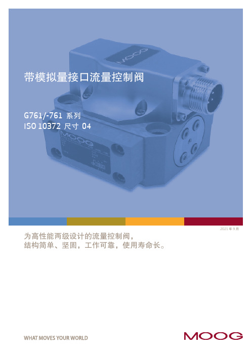
为高性能两级设计的流量控制阀,结构简单、坚固,工作可靠,使用寿命长。
2021 年 9 月哪里需要最高水平的运动控制性能和设计灵活性,哪里就能看到穆格技术。
通过协作、创新以及世界级水平的技术解决方案,我们将助您攻克最艰巨的工程难关。
穆格旨在帮助您提高机器的性能,获取超乎想象的新体验。
简介 (2)产品概述 (3)工作原理 (5)技术参数 (6)G761/-761 系列伺服阀 (6)安装图 (11)安装要求 (12)电气接线 (13)背景 (14)流量计算 (14)订货信息 (15)备件及附件 (15)相关产品 (16)关于穆格 (17)订货编码 (19)本产品样本用于为具有一定专业知识的客户提供信息和参数。
为确保获得系统功能和系统的安全性,请对照此样本仔细查看产品的适用性。
文中所述产品如有任何更改,恕不另行通知。
如果有任何疑问,请与穆格公司联系。
Moog 是穆格公司及其子公司的注册商标。
除非另有说明,文中出现的所有商标均为穆格及其子公司所有。
产品概述阀的设计 带阀芯、阀套和干式力矩马达的两级伺服阀安装型式ISO 10372-04-04-0-92P、A、B 和 X 口最大工作压力• 铝制阀体:315 bar (4,500 psi)• 钢制阀体:350 bar (5,000 psi)T 口最大工作压力210 bar (3,000 psi)先导阀喷嘴挡板阀为 35 bar/每一节流边 (500 psi /每一节流边)时的额定流量Δp N 0.5 至 75 l/min (0.125 至 19.5 gpm)从 0 至 100% 行程的阶跃响应时间标准响应型: < 8 ms 高响应型: < 6 ms 超高响应型: < 4 ms在有潜在危险的环境中可以选用本质安全型和防爆型伺服阀。
特殊型号均经过 FM、ATEX、CSA、TIIS 和 IECEx标准认证。
详细信息请联系穆格获取。
文件文件名称说明备注穆格文件号目录G761/-761 系列基本信息注:请访问 /industrialCDL6642手册G761/-761CDS6673G761K/-761K 本质安全型系列CDS6769安装图G761/-761 1系列总体设计CB59420G761K/-761K 系列,2 组线圈CA33637G761/-761 系列流量控制伺服阀是可用作三通和四通节流型流量控制阀,用于四通阀时控制性能更好。
穆格D661系列伺服阀说明书

UD-E=0-+10V Re:10KΩ
!"#$%
&"#'
! ! ! UD-B
ID=-IE: 0-±10mA (Re=200)
! IE=-ID: 0-±10mA
UE-B
!" -15V~+32V
IF-B=4-20mA 12mA
!"#$%&RL=100-500Ω
!D
23
UF-B=2-10V, 6V
!"#$%Ra=500
!"# !"#$%"#
!
PN=0.5MPa/
!"
!
! P A B (X
)
T (Y
)
T (Y
)
!
!"#
!"#$%
! * 0-100%
!"#$%&'
!"#$
!"#$%&'( 6
!"#$%&'
!"
24VDC,
18VDC,
32VDC
!"#$ 300mA
!"#$
!"#$%&'(
!"#$%&
!"#$%&$'()% 0V
!"# EMC
!
EMC
EN 55011:1998 B
! EN50082-2:1995A
!
!"#$%&'()*+,-./0 !"#$%&0.75mm2.
!"#$%&'()*
Model 680 型酶标仪中文说明书

注意: 根据 FCC 规定的第 15 部分,该设备经检测应遵从 A 类数码设备的限制。本产品在用于商业场所时, 遵照这些限制将使设备不至于产生有害干扰。如果不按照说明手册安装和使用本设备,它会产生和发射电 磁波频率的能量,从而对电子通讯设施形成有害干扰。在居民区使用本产品造成这类干扰时,应用者将自 费去除干扰。
3
2.2 外表特征 4
1 5
2 3
6
1. 打开仪器后部的闭锁 2. 液晶显示器(LCD) 3. 膜键盘
4. 仪器后盖 5. 打印口(配有内置打印机的类型) 6. 读板仓门
7
8 14
11
10
7. RS-232C 串行接口 8. 仪器序列号 9. 保险丝 10. 电源开关
9 12 13
11. 打印机接口( 没有配有内置打印机的类型) 12. 电源线接口 13. 风扇 14. 通风口
向上移动光标,选择字母或者符号
回到前一界面,向左移动光标
向下移动光标,选择字母或者符号
向右移动光标,改变或者选择某一值或者类型
输入点,改变输入模式
完成或者接受某一设置
输入数字或者酶标板布局的情况
0 / EMP : 空孔
5 / QC : 质控品孔
1 / SMP : 样本孔
6 / CAL : 校准品孔
2 / BLK : 空白孔
7.2
RS-232C 接口参数规格.............………… 43
7.3
680 型酶标仪软件命令语言........…………. 44
vi
1 仪器简介
680 型酶标仪是一款 8 通道、垂直光路,可以测量 96 孔酶标板内容物吸光度的最新酶标仪。该仪器可以 单波长或双波长检测,得到的吸光度值可以显示到小数点后第三位。
MOOG_D636_D638_operatinG_instructions

D636 / D638 SeriesDirect Drive Servo-Proportional Valves with Integrated Digital Electronics and CAN Bus InterfaceOperatingInstructions© 2002 Moog Industrial Controls DivisionMoog Inc., East Aurora, NY 14052-0018Telephone: 716/655-3000, Fax: 716/655-1803, Toll Free: 1-800-272-MOOGAll rights reserved. No part of these operating instructions may be reproduced in any form (print, photocop-ies, microfilm, or by any other means) or edited, duplicated, or distributed with electronic systems without the prior written consent of Moog.Exclusion of LiabilityThese operating instructions were prepared with the greatest possible care and the contents generated ac-cording to the best of the authors' knowledge. However, the possibility of error cannot be prevented and im-provements may be possible. We would be pleased to receive your comments about possible errors or in-complete information.Nevertheless, Moog does not offer any guarantee that the contents conform with applicable legal regula-tions, nor does Moog accept any liability for possible remaining incorrect or incomplete information and the consequences thereof.Changes are possible at any time without prior notice.Part number of the D636 / D638 operating instructionsPlease contact us at the above address and indicate the following part number when ordering these operat-ing instructions:CDS6818TrademarksNote:All product designations mentioned in these operating instructions are trademarks of the respective manufacturers. The absence of the trademark symbols ® or ™ does not indicate that the name is free from trademark protection.Table of Contents1General Information (1)1.1Using the Operating Instructions (1)1.2Proper Use (1)1.3Selection and Qualification of Personnel (1)1.4Electromagnetic Compatibility (EMC) (2)1.5Guarantee and Liability (2)1.6Explanation of Symbols (2)1.7Abbreviations (3)2Safety Instructions (5)3Function and Operational Characteristics of the Servo-Proportional Valves (7)3.1General Information (7)3.1.1Representative Depiction of a Direct Drive Valve (8)3.1.2Permanent Magnet Linear Force Motor (8)3.2Servo-proportional Valve Operational Modes (9)3.2.1Flow Control (Q-Control) (9)3.2.2Pressure Control (p-Control) (9)3.2.3Flow Control and Pressure Control (pQ-Control) (optional for D638) (9)3.2.4Notes on Controller Behavior (10)3.3CAN Bus and CANopen (10)3.4Analog Command Inputs (11)3.4.1Flow Command Input ±10 V Floating (12)3.4.2Flow Command Input ±10 mA Floating (12)3.4.3Flow Command Input ±10 mA Single-Ended (13)3.4.4Flow Command Input 4–20 mA Floating (13)3.4.5Flow Command Input 4–20 mA Single-Ended (14)3.4.6Pressure Command Input 0–10 V Floating (D638) (14)3.4.7Pressure Command Input 0–10 mA Floating (D638) (15)3.4.8Pressure Command Input 0–10 mA Single-Ended (D638) (15)3.4.9Pressure Command Input 4–20 mA Floating (D638) (16)3.4.10Pressure Command Input 4–20 mA Single-Ended (D638) (16)3.5Analog Actual Value Outputs (17)3.5.1Actual Flow Value Output 4–20 mA (17)3.5.2Actual Pressure Output 4–20 mA (D638) (17)3.5.3Evaluation of the 4–20 mA Actual Value Output (17)3.6Digital Inputs/Outputs (18)3.6.1Enable Input (optional) (18)3.6.2Digital Outputs (18)3.7Status Display (18)3.7.1Module Status LED (MS) (18)3.7.2Network Status LED (NS) (19)4Technical Data and Scope of Delivery (21)4.1General Technical Data (21)4.2Hydraulic Data (22)4.2.1Servo-Proportional Valve Configurations (23)4.2.2Leakage Port Y (24)4.3Electrical Data (24)4.4Characteristic Curves (25)4.4.1Step Response, Frequency Response, and Flow Diagram (25)4.4.2Flow Characteristic Curve (26)4.4.3Pressure Characteristic Curves (26)4.5Dimensions (Installation Drawing) (27)4.6Mounting Pattern and Mounting Surface (27)4.7Scope of Delivery (28)5Transport and Storage (29)5.1Packaging/Transport (29)5.2Storage (29)6Mounting/Removing and Connection to the Hydraulic System (31)6.1Mounting the Servo-Proportional Valve (32)6.2Removing the Servo-Proportional Valve (33)7Electrical Connection (35)7.1Pin Assignment (36)7.1.1Valve Connector (36)7.1.2CAN Connector (37)7.2Wiring CAN Networks (38)7.2.1Cable Lengths and Cable Cross Sections in CAN Networks (39)7.2.2Suitable Cable Types (40)8Starting-Up the Servo-Proportional Valve (41)8.1Filling and Flushing the Hydraulic System (42)8.2Venting (D638) and Starting-Up the Hydraulic System (43)8.3Connection to the CAN Bus (43)9Maintenance and Repair (45)10Trouble Shooting (47)11Tools, Replacement Parts, and Accessories (49)11.1Tools for 6+PE Pin Connectors (49)11.2Replacement Parts and Accessories D636 / D638 (49)12Appendix (51)12.1Additional Literature (51)12.2Quoted Standards (51)12.3Addresses (52)13Index (53)For your notes.1 General Information Using the Operating Instructions 1 GeneralInformation1.1 Using the Operating InstructionsThese operating instructions apply only to Direct Drive Valve series D636 (flow control valves) and D638 (pressure control valves) with integrated digital electronics and CAN bus interface. The instructions contain the most important information for ensuring safe operation of servo-proportional valves.The operating instructions must be stored near the servo-proportional valve or the upper level machine so that they are readily accessible at all times.All persons responsible for mechanical planning, assembly, and operation must read, understand, and follow all points contained in these operating in-structions. This requirement applies especially to the safety instructions. Complying with the safety instructions helps to avoid accidents, problems, and errors.It is absolutely essential for the user to know the safety instructions as well as nationally and internationally applicable safety regulations in order to handle the servo-proportional valve safely and operate it trouble-free.1.2 Proper UseD636 and D638 Direct Drive Valves are always operated as a component of a complete upper level system, for example in a machine.They must be used only as control elements to control flow and/or pressure in hydraulic circuits that regulate position, speed, pressure, and power. The valves are intended for use with mineral oil-based hydraulic oils. The use of other media must be approved by Moog.Use for other purposes or for purposes that extend beyond this description is not allowable.Operation is allowable only in industrial environments in accordance with the DIN EN 50081-2 standard.Operation in potentially explosive areas is not allowable.Proper use also includes observation of the operating instructions and com-pliance with the inspection and maintenance regulations.1.3 Selection and Qualification of PersonnelOnly properly trained and instructed personnel with the necessary knowl-edge and experience must work with and on servo-proportional ing the operating instructionsProper useSelection and qualifica-tion of personnel1 General Information Electromagnetic Compatibility (EMC) 1.4 Electromagnetic Compatibility (EMC)The D636 and D638 servo-proportional valves comply with the following standards:DIN EN 50081-2Electromagnetic compatibility (EMC) - Generic emis-sion standard - Part 2: Industrial environment DIN EN 61000-6-2Electromagnetic compatibility (EMC) - Part 6-2: Ge-neric standards - Immunity for industrial environ-mentsDIN EN 55011Industrial, scientific and medical (ISM) radio-fre-quency equipment - Radio disturbance characteris-tics - Limits and methods of measurementsThe D636 and D638 servo-proportional valves must not be used in residen-tial, commercial and light industry as defined by the DIN EN 50081-1 and DIN EN 50082-1 standards.1.5 Guarantee and LiabilityIn general, our "General Terms and Conditions for Sales" apply. These con-ditions are given to the operator upon contract closure.Among other things, guarantee and liability claims for personal and property damages will not be considered if they are caused by one or more of the following:•Improper use of the servo-proportional valve•Improper mounting, start-up, and maintenance of the servo-propor-tional valve•Improper handling of the servo-proportional valve, such as the use in a potentially explosive, excessively hot, or excessively cold envi-ronment•Failure to follow the operating instructions regarding transport, stor-age, mounting, start-up, and maintenance of the servo-proportionalvalve•Unauthorized structural changes to the servo-proportional valve •Improperly performed repairs•Disasters caused by foreign objects or force majeure1.6 Explanation of SymbolsThe following symbols are used in these operating instructionsImportant informationDanger of damage to machine or materialGeneral danger of injury and deathSpecific danger of injury and deathRegulatory symbols Electromagnetic compatibility (EMC) Guarantee and liabilitySymbols used1.7 AbbreviationsAbbreviations used The following abbreviations are used in these operating instructions:Symbol for filter finenessXSymbol for viscosityµP MicroprocessorCAN C ontroller A rea N etworkCiA C AN i n A utomation user's associationDDV D irect D rive V alveDIN D eutsches I nstitut für N ormung e. V.(German Institute for Standardization)DS D raft S tandard (published by CiA)DSP D raft S tandard P roposal (published by CiA)DSP D igital S ignal P rocessorEMC E lectro m agnetic C ompatibilityEMI E lectro m agnetic I nterferenceEN E uropa-N orm (European standard)FPM Fluorocarbon rubberF.S.F ull S cale output of transducerGND G rou nd (signal ground)ID Id entifierID I nner D iameter (of O-rings for example)ISO I nternational S tandardizing O rganizationLED L ight E mitting D iodeLSS L ayer S etting S ervicesLVDT L inear V ariable D ifferential T ransformer(senses the position of the spool in the valve [position transducer])MS M odule S tatus LEDNAS N ational A merican S tandardNBR N itril B utadiene R ubber (Perbunan, Buna)NS N etwork S tatus LEDp Symbol for p ressurePC P ersonal C omputerPE P rotective E arthPWM P ulse W idth M odulationQ Symbol for volumetric flowVDMA V erband D eutscher M aschinen- und A nlagenbau e. V.(German Machinery and Plant Manufacturers' Association)For your notes.2 SafetyInstructionsSafety instructions The D636 and D638 servo-proportional valves must only be put intooperation and used as described in these operating instructions.They must be operated only as a component of a complete upperlevel system, for example a machine, and only in industrial environ-ments as defined by the DIN EN 50081-2 standard.The D636 and D638 servo-proportional valves must not be used inresidential, commercial and light industry as defined by the DIN EN50081-1 and DIN EN 50082-1 standards.Operation in potentially explosive areas is not allowable.During equipment planning and the use of servo-proportional valves,the safety and accident prevention regulations specific to the type ofusage must be followed. These include, for example:DIN EN 292Safety of machinery - Basic concepts, generalprinciples for designDIN EN 982Safety of machinery - Safety requirements forfluid power systems and their components -HydraulicsDIN EN 60204Safety of machinery - Electrical equipment ofmachinesThe manufacturer and the operator of the complete upper levelsystem (mechanical equipment, for example) are responsible forcompliance with the national and international safety and accidentprevention regulations that apply to each particular case.Modifying, changing, and interfering in the internal area of the servo-proportional valve may cause serious injuries and as such is forbid-den.Only properly trained and instructed personnel with the necessaryknowledge and experience must work with and on servo-proportion-al valves.The servo-proportional valves must only be mounted and removed,and electrical and hydraulic connections made by suitably trainedtechnical personnel with the necessary authorization. They mustperform such tasks in accordance with the applicable regulationsand the valve must be in an idle and depressurized state and themachine switched off.While this work is in progress, the machine must be securedagainst restarting, for example by:•Locking the main command device and removing the keyand/or•attaching a warning sign to the main switchOperating machines with leaking servo-proportional valves or aleaking hydraulic system is dangerous and not allowed.When starting-up a servo-proportional valve on a field bus for the first time, we recommend operating the valve in a depressurized state.The servo-proportional valve must only be operated via the configu-ration software if doing so does not endanger the machine and its immediate surroundings.The configuration software must not be operated on a CAN bus if CAN communication is still running.If the valve cannot be operated safely via the configuration software even when the CAN communication is switched off, it must only communicate via a direct (i.e. point-to-point) connection with the configuration software. The valve must be depressurized for this purpose.(To create a direct connection between the configuration software and the valve, unplug the CAN bus cable from the valve and con-nect the valve directly to the PC's CAN bus interface card.) Hydraulic oil can cause serious injuries, burns, and fires if it squirts out under high pressure.Before mounting or removing servo-proportional valves, all pressure lines and reservoirs in the hydraulic circuit must therefore be de-pressurized.Servo-proportional valves and hydraulic connection lines may be-come very hot while in operation.When mounting, removing, or servicing servo-proportional valves,always wear suitable protective equipment such as work gloves.When handling hydraulic fluids, always follow the safety guidelinesapplicable to the product.The instructions in these operating instructions, especially chapter 2(starting on page 5) and chapter 9 (starting on page 45) must beadded to the operating instructions of the complete upper level sys-tem.The allowable environmental conditions (see chapter 4, page 21)must be maintained at all times.Do not transport or store the servo-proportional valves without firstproperly installing the shipping plate.To avoid overheating the servo-proportional valve, mount it in a waythat ensures good ventilation.Do not mount valves directly onto mechanical parts that are subjectto strong vibrations or sudden movement.When mounted on units subject to sudden movement, the spool di-rection should not be the same as the unit's direction of movement.The servo-proportional valves must not be immersed in liquid.Safety instructions3 Function and Operational Characteris-tics of the Servo-Proportional Valves 3.1 General InformationThe D636 valves (flow control valves) and the D638 valves (pressure control valves) are Direct Drive Valves (DDV). The valves are throttle valves for 3-, 2-, 4-, 2x2-way applications and are suitable for electro-hydraulic control of po-sition, speed, pressure, and power - even under high dynamic requirements.A permanent magnet linear force motor is used to drive the spool. In contrast to proportional magnet drives, the linear force motor adjusts the spool in both working directions from the spring-loaded middle position. This gives the servo-proportional valve strong actuating power for the spool as well as good static and dynamic characteristics.The following operational modes are possible:•Flow control (Q-control) (D636)(see chapter 3.2.1, page 9)•Pressure control (p-control) (D638)(see chapter 3.2.2, page 9)•Flow control and pressure control (pQ-control) (optional for D638) (see chapter 3.2.3, page 9)The digital driver and control electronics are integrated into the valve. The valve electronics contain a microprocessor system which performs all im-portant functions via the valve software it contains. The digital electronics enable the valve to be controlled across the entire working range without drift and almost regardless of the temperature.The valves are parameterized, activated, and monitored via the built-in CAN bus interface in accordance with the CiA standard DSP 408 (device profile fluid power technology).In addition, up to two analog command inputs and up to two analog actual value outputs with programmable functions are available as options. Benefits of using D636 / D638 Direct Drive Valves:•Direct drive with permanent magnet linear force motor that provides high actuating power•Pilot oil not required•Pressure independent dynamics•Minimal hysteresis and high response characteristics•Minimal current requirement at and close to hydraulic null(hydraulic null is the position of the spool at which the pressures of asymmetrical spool are equally high in both blocked working ports)•Standardized spool position signal•Electrical null point adjustment is parameterizable•If the electrical supply fails, a line breaks, or emergency stop is activated, the spool returns to the predefined spring-loadedposition without overshooting a working position (fail-safe).•Flow control and optional pressure control (on D638) with only one valve•CAN bus interface•optional analog inputs and outputs Function of the servo-proportional valves: throttle valves Operational modes:Q-, p-, pQ-control Digital valve electronics CAN bus interface Benefits of the D636/D638 series3.1.1 Representative Depiction of a Direct Drive ValveFigure 1: Representative depiction of the servo-proportional valve3.1.2 Permanent Magnet Linear Force MotorFigure 2: Representative depiction of the permanent magnet linear force motorThe permanent magnet linear force motor is a permanently magnetically ex-cited differential motor. A portion of the magnetic force is already integrated with the permanent magnet. This makes the linear force motor's power re-quirement considerably lower than that of comparable proportional magnets. The linear force motor drives the spool of the servo-proportional valve. In the zero current condition, the centering springs determine the starting position of the spool. The linear force motor enables the spool to be guided in both directions from the starting position, the linear force motor's actuating power being proportional to the coil current. The strong forces from the linear force motor and the centering springs enable precise movement of the spool, even when working against flow and frictional forces.3.2 Servo-proportional Valve Operational Modes3.2.1 Flow Control (Q-Control)During this operating mode the spool position is controlled. The predefined command signal corresponds to a particular spool position. The spool posi-tion is proportional to the electrical signal.The command signal (spool position command) is fed to the valve electron-ics. A position transducer (LVDT) measures the spool's actual position and forwards this information to the valve electronics. The electronics compares the actual spool position and command signal and generates a current to drive the linear force motor, which then brings the spool into the correct po-sition.The position command can be influenced with parameters in the valve soft-ware (for example: linearization, ramping, dead band, sectionally defined amplification, etc.).3.2.2 Pressure Control (p-Control)During this operating mode of the D638 valve the pressure in port A is con-trolled. The predefined command signal corresponds to a particular pressure in port A.The command signal (pressure command in port A) is transmitted to the valve electronics. A pressure transducer measures the pressure in port A and feeds this to the valve electronics. The electronics compares the actual pressure signal and command signal and generates a current to drive the linear force motor, which then brings the spool into the correct position.The pressure control function can be influenced with parameters in the valve software (for example: linearization, ramping, dead band, sectionally defined amplification, etc.). The pressure regulator is carried out as an extended PID controller. In the valve software, you can set the parameters of the PID con-troller.3.2.3 Flow Control and Pressure Control (pQ-Control)(optional for D638)This is a combination of flow and pressure control for which both command signals (external flow and pressure limit command) must be present.The following are examples of possible combinations:•Flow control with pressure limiting control•forced changeover from one operating mode to the other Permanent magnet linear force motorQ-Control: Controlling the spool positionp-control: Controlling the pressure in port A pQ-control3.2.4 Notes on Controller BehaviorThe resulting flow depends not only on the position of the spool, but also onthe pressure drop ∆p on the individual control edges.At 100 % flow command signal with a rated pressure drop ∆p N of 35 bar(500 psi) per control edge, the result is the rated flow Q N . By altering thepressure drop, the flow Q also changes assuming a constant command sig-nal, as shown by the following formula:N Np p Q Q ∆∆=Q [l/min]=actual flowQ N [l/min]=rated flow ∆p [bar]=actual pressure drop per control edge∆p N [bar]=rated pressure drop per control edge The following exert significant influence on the controlled system:• Rated flow Q N• Actual pressure drop ∆p per control edge• Load stiffness• Control volume being regulated by port A (D638 only)Depending on differences in mechanical construction (such as volume,pipework, branching, reservoirs, etc.), different types of controller optimiza-tions may be required in pressure control. These controller optimizations canbe carried out with the configuration software via the CAN bus interface.3.3 CAN Bus and CANopenThe servo-proportional valve is equipped with a CAN bus interface and canbe operated within a CAN network.The CAN bus is a differential 2-wire bus and was initially developed to facili-tate rapid and interference-free networking of components in automobiles.But thanks to its many advantages and high level of reliability, the CAN busis also suitable for applications within machines and has proven its useful-ness as a widely accepted standard.CANopen is a standardized communication profile for simple networking ofCANopen-compatible devices from many different manufacturers.The communication profile complies with the DS 301 standard, version 4.0,and is provided by CiA.The CANopen standard defines various device profiles to enable connectionof different types of devices, including for example: drives, controllers, angletransmitters, etc.The function of the D636 and D638 series valves corresponds to the deviceprofile for proportional servo valves in accordance with the CiA standardDSP 408. This device profile is based on a profile established by a workinggroup within the VDMA entitled "Device Profile Fluid Power Technology".Formula for calculating the flow QCAN bus interface CANopen communica-tion profile (CiA stand-ard DS 301, version 4.0)Device profile for pro-portional servo valves (CiA standard DSP 408)The machine controller or other CAN bus nodes can use the CAN bus to ex-change data with the servo-proportional valve in real time. This data includes command signals and actual values as well as control and status reports. In addition to this real time transmission, configuration and parametric data can be exchanged between the controller and the valve at any time.The controller or other CAN bus nodes transmit command signals, device control commands, and configuration data via the CAN bus to the servo-pro-portional valve.The controller or other CAN bus nodes can read actual values, status infor-mation, and the current configuration from the servo-proportional valve.The integrated valve electronics can take over device-specific and drive-specific functions like command signal ramping or dead band compensation. This can relieve the external controller and the CAN communication because external controllers previously had to perform these functions themselves and the interpolated intermediate values had to be transmitted via the CAN bus.Monitoring, error recognition, and diagnostic functions enable recognition of device malfunctions via the CAN bus.3.4 Analog Command InputsDepending on the valve model, various analog command inputs for flow control and/or pressure control are available. (Pin assignment of the valve connector: see Table 6, page 36)Command input Benefits±10 V or 0-10 V Simple measurement of the signal with an oscillo-scope, for example±10 mA or 0-10 mA In contrast to the 4–20 mA command input, less power is required at low command signals; large transmissionlengths are possible4–20 mA Line break monitoring and large transmission lengthspossibleTable 1: Available Analog command inputsAll current inputs are available as floating or single-ended versions.All voltage inputs are floating, but can be connected externally assingle-ended inputs.Integrated valveelectronicsMonitoring, errorrecognition, anddiagnostic functionsAnalog commandinputs3.4.1Flow Command Input ±10 V FloatingFigure 3: Flow command input ±10 V floating (circuit and characteristic curve)The spool stroke is proportional to the input voltage U in .U in = +10 V100 % valve opening P ð A and B ð T U in = 0 VSpool in hydraulic null position U in = -10 V 100 % valve opening P ð B and A ð TThis command input is a floating, differential input. (The potential differ-ence of each input to GND must be between -15 V and +32 V.) If differ-ential voltage is not available, one input pin has to be connected to sig-nal ground according to the required operating direction.3.4.2Flow Command Input ±10 mA FloatingFigure 4: Flow command input ±10 mA floating (circuit and characteristic curve)The spool stroke is proportional to the input current I in .I in = +10 mA100 % valve opening P ð A and B ð T I in = 0 mASpool in hydraulic null position I in = -10 mA 100 % valve opening P ð B and A ð TThe input current I in must be between -25 mA and +25 mA!This command input is a floating input. (The potential difference of eachinput to GND must be between -15 V and +32 V.) If a floating currentsource is not available, one input pin has to be connected to signalground according to the required operating direction.Flow command input±10 V floatingFlow command input±10 mA floatingFigure 5: Flow command input ±10 mA single-ended (circuit and characteristic curve)The spool stroke is proportional to the input current I in .I in = +10 mA100 % valve opening P ð A and B ð T I in = 0 mASpool in hydraulic null position I in = -10 mA 100 % valve opening P ð B and A ð T The point of reference for this command input is GND.The input current I inmust be between -25 mA and +25 mA!Depending on the required operating direction, one of the two input pinsmust not be connected.3.4.4Flow Command Input 4–20 mA FloatingFigure 6: Flow command input 4–20 mA floating (circuit and characteristic curve)The spool stroke is proportional to the input current I in .I in = 20 mA100 % valve opening P ð A and B ð T I in = 12 mASpool in hydraulic null position I in = 4 mA 100 % valve opening P ð B and A ð TThe input current I in must be between -25 mA and +25 mA!This command input is a floating input. (The potential difference of eachinput to GND must be between -15 V and +32 V.) If a floating currentsource is not available, one input pin has to be connected to signalground according to the required operating direction.Command signals I in < 3 mA (due to line break, for example) indicate anerror during flow control. The valve is switched off for safety reasonsand goes into fail-safe position.Flow command input4–20 mA floating。
美国穆格型号
美国MOOG电液伺服阀穆格电液伺服阀 MOOG伺服阀穆格伺服阀穆格MOOG三级伺服阀MOOG直动式伺服阀D634-319C D634-399C D634-1003 D634-1005 D634-1007 D634-1008 D634-514A D634-557 D634-394CD634-1009 D634-1010 D634-1011 D634-1012 D634-1013 D634-1014 D634-1015 D634-1016 D634-1018D634-1019 D634-1023 D634-1024 D634-1025 D634-1026 D634-1027 D634-1028 D634-1029 D634-1031D634-1032 D634-1033 D634-1034 D634-1035 D634-1036 D634-1037 D634-1040 D634-1041 D634-1042D634-1043 D634-1045 D634-1046 D634-1047 D634-1049 D634-1050 D634-1051 D634-1052 D634-1053D634-1054 D634-1055 D634-1056 D634-1057 D634-1058 D634-1059 D634-1060 D634-3001 D634-301CD634-305C D634-307C D634-308C D634-317C D634-318C D634-322C D634-324C D634-326C D634-384CD634-327C D634-330C D634-331C D634-335C D634-341C D634-345C D634-346C D634-358C D634-361CD634-362C D634-368C D634-371C D634-372C D634-373C D634-374C D634-381C D634-383C D633Z7397D634-385C D634-386C D634-387C D634-388C D634-389C D634-390C D634-391C D634-392C D633Z7383D634-396C D634-397C D634-398C D634-400C D634-402C D634-403C D634-404C D634-405C D634-1001D634-406 D634-501A D634-502A D634-503 D634-504 D634-508 D634-511 D634-512A D634-513 D634-515 D634-516A D634-517 D634-518A D634-520A D634-521 D634-524A D634-525AD634-526D634-527A D634-528A D634-529A D634-530A D634-531 D634-532 D634-533 D634-534D634-536AD634-537A D634-538A D634-539 D634-540A D634-541 D634-542A D634-543A D634-544AD634-545D634-546A D634-547 D634-548 D634-550 D634-551 D634-552 D634-553A D634-554A D634-555 D634-558 D634-559 D634-560 D634K2000C D634K2001C D634K2002C D634K2003C D634K2004C D634K2005C D634K2006C D634K2007C D634K2008C D634K2009C D634K2010C D634K2011CD634K2012C D634K2013CD634K2014C D634K2015C D634K2016C D634K2017C D634K2018C D634K2019C D634K2020D634Z1020D634Z1021 D634Z1022 D634Z1038 D634Z1044 D634Z314C D634Z351C D634Z359CY D634Z360CD634Z360CYD634Z380C D634Z395C D634Z505A D634Z509 D634Z510 D634Z549A D633E703 D633E704D633E713AD633E714A D633E7365 D633E7366 D633E7411 D633K2000B D633K2001B D633K2002BD633K2003BD633K2005B D633K2006B D633K2007B D633K2008B D633K2009B D633K2010B D633K2011BD633K2012BD633K2013B D633K2014B D633K2015B D633K2017B D633K2018B D633K2019B D633K2020BD633K2021BD633K2022B D633K2023B D633K2024B D633K2025B D633K2026B D633K2027B D633K2028BD633K2029BD633K2030B D633K2031B D633K2032B D633K2033B D633K2034B D633K2035B D633K2036BD633K2037BD633K2038B D633K2039B D633K2040B D633K2041B D633K2042B D633K2043B D633K2044BD633K2045BD633K2046B D633K2047B D633K2048B D633K2049 D633K2050 D633K2051 D633Z303B D633Z305B D633Z313BD633Z317B D633Z338B D633Z348B D633Z371B D633Z379B D633Z480B D633Z506B D633Z528B D633Z529BD633Z532B D633Z539B D633Z557B D633Z570B D633Z585B D633Z586B D633Z587B D633Z588B D633Z589BD633Z590B D633Z7309 D633Z7324 D633Z7337 D633Z7352 D633Z7353 D633Z7361 B67728-001 B67728-002B67728-003 A03665-060美国Moog伺服阀说明:美国Moog伺服阀MOOG穆格伺服阀D633,D634系列,G761-3005,G761-3004,G761-3003,G761-3002,G761-3001,J761,J072,J869,G631 G761系列伺服阀 D791三级伺服阀 D661电反馈式伺服 72系列机械反馈伺服 D633/D634直动式伺服阀功率级阀型号/先导级 MOOG机能代号 D661-4651/ C41156-421 G35JOAA6VSX2HA D661-4652/ C4 1156-421 G15JOAA6VSX2HA D661-4636/C41156-421 G60KOAA5VSX2HA D661-4469C/C41156-421 G75KOAA6VS X2HA D661-4697C/C41156-421 G15JOAA5VSX2HA D661-4033/ C41156-421 P80HAAF6VSX2-A D661-4059/C41 156-411 P80HAAF6VSX2-B D661-4444C/C41156-421 G60JOAA6VSX2HA D661-4443C/C41156-421 G45J0AA6VS X2HA D661-4506C/C41156-421 G23J0AA6VSX2HA D661-4539C/C41156-421 G35JOAA5VSX2HA MOOG型号/先导级 MOOG机能代号 D662Z4311K/D630-072A P01JXMF6VSX2-A D662-4010/D061-8411 D02HABF6VSX2-A D662Z 4336K/D630-272D P01JXMF6VSX2-A MOOG型号/先导级 MOOG机能代号 D663Z4307K/D630Z067A P02JONF6VS X2-A D663-4007/D061-8412 L03HABD6VSX2-A MOOG型号/先导级 MOOG机能代号 D663Z4307K/D630Z067A P 02JONF6VSX2-A D663-4007/D061-8412 L03HABD6VSX2-A D634-341C R40K02M0NSS2 D634-319C R40KO2M0NS P2 D633-333B R16KO1F0NSS MOOG型号/先导级 MOOG机能代号 D791-5009/D761-2612 S16J0QA6VSB0-P D7 91-4025/ S25J0PA6VSX2-A D791-4001/待查 S25J0QB6VSX2-B D791-4002/D761-2617 S25J0QB5VSX2-B D791-4028/D761-2619 S25J0QB6VSX2-B D791-4046/D761-2619 S25J0QA6VSX2-B MOOG型号 MOOG机能代号 07 2-559A S15F0FA4VBL, 072-558A S22FOFA4VBL《新型号:072-1203-10》。
莫格(Moog)实时过程监控系统说明书
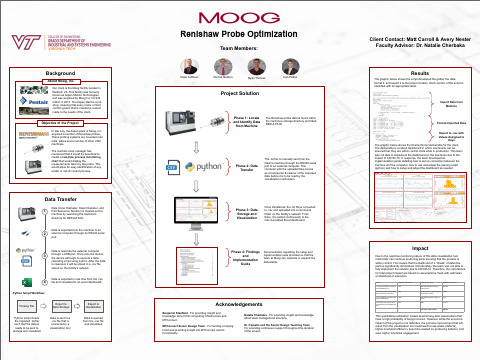
Phase 3: Data Storage and Visualization
Once transferred, the .txt file is converted to .csv and uploaded into a communal folder on the facility’s network. From there, it is pulled continuously to the macro-enabled Excel dashboard.
Phase 4: Findings and
Implementation Guide
Documentation regarding the setup and implementation was provided so that the team at Moog can replicate or expand the deliverable.
Client Contact: Matt Carroll & Avery Nester Faculty Advisor: Dr. Natalie Cherbaka
Results
The graphic below shows the script developed the gather the data, format it, and export it to the proper location. Each section of the script is identified with its appropriate label.
Background
About Moog, Inc.
Our client is the Moog facility located in Radford, VA. This facility was formerly known as Aspen Motion Technologies and was acquired by Moog Inc. for $34 million in 2013. The Aspen plant is a job shop, meaning that every motor or fluid control system that is created is custom made to the needs of the client.
MOOG伺服阀J761-原理……MOOG办事处

MOOG伺服阀J761-003原理……MOOG办事处美国穆格MOOGJ761-003,J761-003系列直动式伺服阀型号:D633,D634系列生产厂家:MOOG 产品说明:高性能直动式伺服阀,由线性力马达直接驱动阀芯运,阀内带有电子放大器对阀芯位置进行闭环控制。
直动式设计避免了先导级的泄漏损失,且动态响应与系统工作压力无关。
安装底面符合ISO4401标准。
频率响应:70HZ阶跃响应:15ms流量控制:3.8-100l/min(1-26gpm)最大工作压力:31.5Mpa该阀适应于金属压制设备,例如剪板机,折弯机,弯管机,木材压机.另外我司优势提供意大利atos阿托斯全系列!备有常规阀现货期待您的来电咨询!!!MOOG伺服阀J761-003原理……MOOG办事处MOOG伺服阀J761-003原理……MOOG办事处格公司(MOOG)是全球电液伺服元件及伺服系统设计及制造领域的领导者,由电液伺服阀的发明者William C. Moog于1951年创立。
产品广泛应用于飞机、卫星、航天飞机、火箭以及各种工业自动化设备。
在工业领域,注塑设备及吹塑设备的伺服控制是我们的重要研究领域之一。
MOOG 是最早进入全电动注塑行业的专业控制厂商之一,向合作伙伴提供DBS、DBM、DS2000 系列驱动器FASTACT 系列电机。
DS2000 驱动器和FAS T 交流伺服电机具有以下一些特点:驱动器可接受三相,50HZ,65到506V间的任意电压;可设定控制交流伺服电机或异步电机;电流环可根据伺服电机特点配置,并按DC BUS变化自动调节,同时提供 B.E.M.F 补偿以及相位自校正功能;速度环内集成了三种数字滤波器,动态性能良好,等等MOOG伺服阀原理J761-003&MOOG办事处MOOG伺服阀J761-003 现货供应!常用系列:D634系列,J761系列,G761系列, D791系列;D792系列,D661系列;D662系列;D663系列;D664系列;D665系列;D633系列等MOOG品牌最早起源于航空航天军事工业领域伺服阀及系统制造,主要经营伺服阀,伺服控制器,电动缸,伺服电机,伺服控制软件,行业应用领域广泛,涉及钢铁冶金,电力电站系统,注塑吹塑成型,材料试验,汽车测试仿真系统,航空测试仿真系统等,MOOG伺服阀J761-003/J761-004稳定可靠全部采用进口低飘移、高稳定度的运算放大器,使控制系统能长期、可靠、稳定地工作。
MOOG伺服阀说明书1
Servovalveswith integrated Electronics D791 and D792 SeriesQ [l/min]=max. flowD p [bar]=valve pressure dropwith Q A K [cm 2]=spool drive area p X [bar]=pilot pressure The pilot pressure p X has to be at least 15 bar above the returnpressure of the pilot stage.D791 and D792 SeriesThree stage servovalvesPrinciple of operationAn electrical command signal (set point, input signal) is applied to the integrated control amplifier which drives a current through the pilot valve coils. The pilot valve produces differential pressure in its control ports. This pressure difference results in a pilot flow which causes main spool dis-placement.The position transducer which is excited via an oscillator measures the position of the main spool (actual value, position voltage).This signal then is demodulated and fed back to the control amplifier where it is compared with the command signal. The control amplifier drives the pilot valve until the error between command signal and feedback signal is zero. Thus, the position of the main spool is proportional to the electrical command signal.Q Q p p NN=∆∆p 2,510QA pX -2K≥⋅⋅∆The actual flow depends on the electrical command signal and the valve pressure drop, and may be calculated using the square root function for a sharp-edged orifice.The flow value Q calculated in this way should not exceed an average flow velocity of 30 m/s in ports P, A, B and T.Q [l/min]=calculated flow Q N [l/min]=rated flowD p [bar]=actual valve pressuredropD p N [bar]=rated valve pressuredrop2If large flow rates with high valve pressure drops are required, an appropriate higher pilot pressure has to be chosen to overcome the flow forces. An approximate value can be calculated as follows:Our quality management system is certified in accordance with DIN EN ISO 9001.This catalogue is for users with technical knowledge. To ensure that all necessary characteristics for function and safety of the system are given, the user has tocheck the suitability of the products described here.In case of doubt please contact MOOG.The flow control servovalves D791and D792 Series are throttle valves for 3-way and preferably 4-way applications. These three stage servovalves have been especially developed for such demanding applications where high flow rates and at the same time extreme dynamic performance require-ments must be met. The design of these valves is based on the well known D079 Series. The inte-grated electronics has been replaced by a new design applying SMD technology. The valves areoffered with pilot valves of D761or D765 Series, optional standard response or high response versions are available. Series D791 can de-liver rated flow up to 250 l/min,Series D792 is available with rated flow up to 1000 l/min.These valves are suitable for pres-sure or force control, position and velocity control systems with high dynamic response requirements.D791 and D792 SeriesGeneral technical dataOperating pressure rangeMain stage Ports P, A and B with X internal up to 315 bar with X externalup to 350 bar Port T with Y internal up to 210 bar Port T with Y external up to 350 barPilot valve Ports P, A and B D761, D765 Series up to 315 bar Port Tup to 210 barTemperature rangeAmbient -20 to +60 °C Fluid-20 to +80 °CSeal material FPM, others on requestOperating fluid Mineral oil based hydraulic fluid (to DIN 51524), others on request Viscosityrecommended 15 to 100 mm²/s Class of cleanlinessThe cleanliness of the hydraulic fluid greatly effects the per-formance (spool positioning, high resolution) and wear (metering edges, pressure gain, leakage) ofthe valve.3T B P A3 stage ServovalveD791 / D792 Series with Pilot valve D765 SeriesRecommended cleanliness classfor normal operation:ISO 4406 < 14/11for longer life:ISO 4406 < 13/10System filtrationPilot valve:High pressure filter (without by-pass, but with dirt alarm) mountedin the mainflow and if possible,directly upstream of the servovalve.Main stage:Main stage: high pressure filter asfor the pilot stage. In combination with a fast regulating VD-pump a bypass filter is possible.Filter rating recommendedfor normal operation:ß10 ³ 75 (10 µm absolute)for longer life:ß5 ³ 75 ( 5 µm absolute)Installation options any position, fixed or movable Vibration 30 g, 3 axes Degree of protection EN 60529: IP 65 (with mating con-nector mounted)Shipping plate Delivered with an oil sealed ship-ping plate4Model . . . .TypeD791 . . . . S . . .Mounting patternISO, but X and Y do not corres-ISO 10372-06-05-0-92pond to ISOValve body version 4-way3-stage with bushing spool assembly Pilot valve2-stage, optional D761 or D765 SeriesPilot connection optional, internal or externalX and Y Mass[kg]13Rated flow (± 10%) at D p N = 35 bar per land [l/min]100160250Response time*for 0 to 100% stroke (depen-dent on pilot valve)[ms]3 to 10Threshold*[%]< 0,2Hysteresis*[%]< 0,5Null shiftwith D T = 55 K [%]< 2Null leakage flow*total, max.[l/min]5710Pilot leakage flow*max., for 100% step input (de-pendent on pilot valve)[l/min]4 to 11Main spool stroke [mm]1,61,62,0Main spool drive area[cm²]2,85* measured at 210 bar pilot or operating pressure, fluid viscosity of 32 mm²/s and fluid temperature of 40 °CValve flow diagramTypical characteristic curves measured at 210 bar pilot or operating pressure, fluid viscosity of 32 mm²/s and fluid temperature of 40 °CFrequency responsefor valves with different rated flows and different pilot valvesD791 SeriesTechnical dataModel . . . .TypeD792 . . . . S . . .Mounting pattern Moog StandardValve body version 4-way3-stage with bushing spool assembly Pilot valve2-stage, optional D761 or D765 SeriesPilot connection optional, internal or externalX and Y Mass[kg]17Rated flow (± 10%) at D p N = 35 bar per land [l/min]4006308001000Response time*for 0 to 100% stroke (depen-dent on pilot valve)[ms]4 to 12Threshold*[%]< 0,2Hysteresis*[%]< 0,5Null shiftwith D T = 55 K [%]< 2Null leakage flow*total, max.[l/min]10141414Pilot leakage flow*max., for 100% step input (de-pendent on pilot valve)[l/min]6 to 16Main spool stroke [mm]1,81,92,64,0Main spool drive area[cm²]3,87,147,147,14* measured at 210 bar pilot or operating pressure, fluid viscosity of 32 mm²/s and fluid temperature of 40 °CValve flow diagramTypical characteristic curves measured at 210 bar pilot or operating pressure, fluid viscosity of 32 mm²/s and fluid temperature of 40 °C Frequency responsefor valves with different rated flows and different pilot valvesD792 SeriesTechnical data5D791 SeriesInstallation drawing with Pilot valve D761 Series Conversion instructionConversion instruction67Spare parts and accessories for D791 SeriesD791 SeriesInstallation drawing with Pilot valve D765 SeriesSpare parts, Accessories8Note: The X and Y tubes have to be connected to the MOOG valve body by fittings.Mounting surface needs to be flat within 0,02 mm. Average surface finish value, Ra, better than 1µm.D792 SeriesInstallation drawing with Pilot valve D761 SeriesConversion instructionConversion instructionD792 SeriesInstallation drawing withPilot valve D765 SeriesSpare parts, AccessoriesSpare parts and accessories for D792 Series910General requirementsD791 and D792 SeriesValve electronics with supply voltage ± 15 VoltCommand signal 0 to ±10 V Valves with voltage command inputThe spool stroke of the valve is proportional to (U D – U E ). 100%valve opening P ç A and B ç T is achieved at (U D – U E ) = +10 V . At 0 V command the spool is in a centred position.The input stage is a differential amplifier. If only one command signal is available, pin D or E is connected to signal ground ^(pin C) according to the required operating direction (to be done at the mating connector).Command signal 0 to ±10 mA Valves with current command inputThe spool stroke of the valve is proportional to (I D – I E ). 100%valve opening P ç A and B ç T is achieved at (I D – I E ) = +10 mA. At 0 mA command the spool is in a centred position.Either pin D or E is used according to the required operating direc-tion. The unused pin is left open (not connected at the mating con-nector). The input pins D and E are inverting.Actual value 0 to ±10 VValves with voltage command inputThe actual spool position value can be measured at pin F. This signal can be used for monitoring and fault detection purposes.The spool stroke range corres-ponds to ±10 V. 100% valve ope-ning P ç A and B ç T corresponds to +10 V.Actual value 0 to ±10 mA or 4 to 20 mAValves with current command inputThe actual spool position value can be measured at pin F. This signal can be used for monitoring and fault detection purposes.The spool stroke range cor-responds to ±10 mA (4 to 20 mA).100% valve opening P ç A and B ç T corresponds to +10 mA (20 mA).r Supply ± 15 VDC ± 3%. Ripple <50 mV pp . Current consumption max. ± 250 mAr All signal lines, also those of external transducers, shieldedr Shielding connected radially to ^ (0V), power supply side, and connected to the mating connector housing (EMC)r EMC : Meets the requirements of EN 55011/03.91 class B,EN 50081-1/01.92, and EN 50082-2/03.95, performance criterion class Ar Protective grounding lead ³ 0,75mm 2r Note: When making electrical connections to the valve (shield,protective grounding) appropriate measures must be taken to ensure that locally different earth potentials do not result in excessive ground currents. See also MOOG Application Note AM 353 E.Wiring for valves with 6+PE pole connector to DIN 43563 and mating connector (metal shell) with leading protective grounding connection ().D791 und D792 SeriesOrdering information11Type designationModel-Number Preferred configurations are highlighted.All combinations may not be available.Options may increase price.Technical changes are reserved.B A M /W A /3000 P r i n t e d i n G e r m a n yMOOG GmbHHanns-Klemm-Straße 28D - 71034 Böblingen Postfach 1670D - 71006 Böblingen Telefon (07031) 622-0Telefax (07031) 622-191MOOG Controls Limited Ashchurch Tewkesbury Gloucestershire GL20 8NATelephone (01684) 29 66 00Telefax (01684) 29 67 60Australia Melbourne Austria Vienna Brazil São Paulo Denmark Birkerød England Tewkesbury Finland Espoo France Rungis Germany BöblingenHong Kong Kwai Chung India Bangalore Ireland Ringaskiddy Italy Malnate Japan Hiratsuka Korea Kwangju Philippines Baguio Russia Pavlovo Singapore Singapore Spain Orio Sweden Gotenborg USA East Aurora (NY)D791/2 - En / Rev1 / 05.98。
MOOG伺服阀D660 的中文样本
此目录中所述阀系列已顺利通过了欧洲电器标准要求的 EMC 测 试。请参阅电气控制部分的相关参考内容。
D661K、D662K、D663K 和 D664K 系列阀还适合在潜在爆炸性 环境、安全类型为 〃d〃(符合 DIN EN 50018 的 〃d〃 型防燃 外壳设备)等级 II 2G EEx d C-C2H2 T5、NEMKO 02ATEX272、 CE 0123 的设备中使用。重要事项:请注意安装尺寸和其它电气 连接方式有所变化。
04可选择的型故障保险如果bar必须用外控外排口可选择的外排口必须用四通阀需使用另一个t160lmin159gpm四通阀带对中弹簧需使用另一个t160lmin159gpm2x2通外接阀五通阀d660系列d661技术参数在先导级控制压力或系统工作压力为210bar3050psi油液粘度为32mm和油液温度为40参见推荐的控制连接方式的液压机能符号型号类型d661安装形式符合iso标准多一个iso440105阀的类型四通2x2通和五通第二级为标准滑阀先导阀伺服射流管servojet标准流量大流量先导级连接可选择内控式或外控式重量kglb5612356123额定流量bar75psi每一节流边lmingpm30807915921122113080791592112211工作压力先导阀
伺服射流管先导阀具有很高的无阻尼自然频率 (500 Hz),因此 这种阀的动态响应较高。
性能可靠 。 伺服射流管 ServoJet ® 先导阀能给出高效率的压
力(输入满标定信号时,可达 80% ∆p),对于长行程主阀芯 也可取得很可靠的位置精度。
也能获得较理想的控制力,使得即使有污染影响和液动力干扰
QN [l/min] = 阀的额定流量 ∆p [bar] ∆pN [bar]
- 1、下载文档前请自行甄别文档内容的完整性,平台不提供额外的编辑、内容补充、找答案等附加服务。
- 2、"仅部分预览"的文档,不可在线预览部分如存在完整性等问题,可反馈申请退款(可完整预览的文档不适用该条件!)。
- 3、如文档侵犯您的权益,请联系客服反馈,我们会尽快为您处理(人工客服工作时间:9:00-18:30)。
长寿命使用: ISO 4406 <16/14/11
滤油器精度
推荐值
常规使用: ß15≥ 75(15 μm 绝对值)
长寿命使用: ß10≥ 75(10 μm 绝对值)
安装位置
任意,固定或运动
振动
30 g,三轴
保护等级
符合 EN 60529 标准,带配套插头时防护等级
为 IP 65。
保护底板
发货时随附
流量 Q [l/min]
M 6 x 60 DIN EN ISO 4762-10.9 可更换的滤油器 更换滤滤器用 O 型密封圈
滤油器 滤油器端盖
用于 P、A、B、T、 T2、X 和 Y 口 B67728 001 参见特殊参数表
A03665 060 060 A67999 200
1 个,ID 12 x Ø 2.0 1 个,ID 17.1 x Ø 2.6
本产品目录中所陈述 的伺服阀已完全通 过了欧 洲 电 器 标 准 的 EMC 测试。请参阅电气控 制部分的相关内容。
伺服阀的实际输出流量与输入 的指令电信号和阀的压降有关。
Q = QN
Δp ΔpN
当阀的压降为某一特定值时,负 载 流 量 则与 阀 锐 边节 流口前后 压 降 的 平方 根 成 正 比, 如 右 式 所示:
油液温度
–20°C ~ +80°C
密封圈材料
丁腈橡胶、氟橡胶或根据用户要求提供
工作介质
石油基液压油(DIN 51524 第 1 – 3 部分的标
准),或根据用户要求选用
油液粘度 推荐值
15 ~ 100 mm2/s
允许值
5 ~ 400 mm2/s
系统过滤要求:先导级:选用高压滤油器(无旁通阀,带污物堵
0
4
20 40 60 80 100 ᆻྔ[ ހ%]
线性流量增益特性 渐进式流量增益特性 (> QN=80 l/min)
20 40
80
幅值比 [dB] -8 -6 -4 -2 0 +2
0
10
频率响应
20
30
ൌ࡛ [ms]
±10%
±90%
±25%
5 10 20 30 50 70 100 200 频率 [Hz]
[MPa]
28
带降压节流器(根据用户要求)
[MPa]
35
响应时间* 分辨率*
0 ~ 100 % 阀芯位移
[ms]
8
[%]
< 0.1
滞环*
[%]
< 0.4
零漂 零位泄漏量*
ΔT = 55 K 总泄漏量(零重叠)
[%] [l/min]
< 2.0 3.0/4.5
先导级泄漏量*
[l/min]
1.7
先导流量*
闭
开
开
闭
备件与附件
O 型密封圈(包括在标准供货中)
用于 P、T、T2、A 和 B 口 用于 X 和 Y 口
5 个,ID 12.4 x Ø 1.8 2 个,ID 15.6 x Ø 1.8
配套插头,防护等级 IP65(未包括在标准供货中)
6+PE 插头
B97007 061
冲洗板
安装板 安装螺钉(未包括在标准供货中)
O452 A453
可选择的 X 和 Y (外控 / 外泄)
XY A B
可选择的 X 和 Y (外控 / 外泄)
XY A B
P T T2
四通阀 故障保险类型 O (若 QN>160 l/min,需同时使用阀口 T2)
P T T2
四通阀 故障保险类型 A: A ➔ T (若 QN>160 l/min,需同时使用阀口 T2)
伺服射流管先导级主要由力矩 主阀阀芯由阀内闭环控制的射 马达、射流管和接收器组成。 流管先导级驱动。
当线 圈 中 有 电 流 通 过 时, 产 生 的电磁力使射流管喷嘴偏离零 位。 大 部分 液 流 集中射 向一 侧
的 接 收 器, 因 此在 接 收 器 的 两 个 控 制口产 生 压 力差, 该 压 差 推动主阀芯移动进而形成先导 流 量。 先导 级 回油 通 过喷 嘴 环 形区域处的排出通道直接流回 油箱。
符合 EN 175201 的 804 部分 用于 P、T、T2、X 和 Y口 B67728 002
安装时所需力矩 13 Nm 200 μm 常规 丁腈橡胶 HNBR 85 ––– B97009 080
典型特性曲线 在先导级控制压力或系统工作压力为 21 MPa、油液粘度为 32 mm2/s 和油液温度为 40 °C 时测得。
流量 - 指令信号曲线 ΔpN = 3.5 MPa/ 每一节流边
20/90 l/min 阶跃响应
40/80 l/min
120/160/200 l/min
200
28 MPa
21 MPa 14 MPa
100% 阶跃信号输入下的最大流量
[l/min]
1.7
主阀芯位移
[mm]
± 1.3
主阀芯的驱动面积
[cm2]
1.35
* 在先导级控制压力或系统工作压力为 21 MPa、油液粘度为 32 mm2/s 和油液温度为 40°C 时测得。
D661 - . . . . . G . . . . A
ISO 4401 - 05 - 05 - 0 - 94 四通
所有参数,请对照此样本仔细查 看产品的适用性。 如有疑问,请与穆格公司联系。
D661-...G....A 系列
常规技术参数
工作压力范围 阀口 P、A 和 B
≤ 35 MPa
阀口 T 和 T2(先导控制油内排) ≤ 21 MPa
阀口 T 和 T2(先导控制油外排) ≤ 35 MPa
温度范围
环境温度
–20°C ~ +60°C
D661-G....A 系列伺服阀 带高精度阀芯阀套
24 伏供电集成式控制放大器
ISO 4401 标准 05 系列
D661-...G....A 系列
二级伺服阀 采用伺服射流管先导级
D661-...G.... A 系 列 伺 服 阀 D661-...G....A 系 列 伺 服 阀 是 可 用 作 二 通、 三 通、 四 通 中 的 集 成 控 制 电 路 是 采 用 了 应 用 的 节 流 型 流 量 控 制 阀。 SMD 技术和 24 VDC 供电的 D661- ... G.... A 系列适用于具 新型系列。 有高动态响应要求的电液位置、 电液速度、电液压力或电液力 伺服射流管先导级的工作特点 控制系统。
200 150
100 80
75 l/min 60 l/min
50
45 l/min
35 l/min
30
30 l/min
20
15 l/min
15
10
8 l/min
8
5
200 160
l/min l/min
120 l/min
90 l/min
80 l/min
40 l/min
20 l/min
3
2
0.5
1
2
3
5
7
28 MPa
21 MPa 14 MPa
28 MPa
21 MPa 14 MPa
ྍو໎ၑ [%] 25 50 75 100
阀芯位移 [%] 25 50 75 100
ྍو໎ၑ [%] 25 50 75 100
120 QN [l/min] 160
ൿԟ [l / min] 20 40 60 80 100 120 140 160 180 200
Q [l/min] = 实际负载流量
Q [l/min] = 伺服阀的额定流量 N
Δp [MPa] = 伺服阀的实际压降 ΔpN[MPa] = 伺服阀的额定压降
若要求阀在较大压降下输出更 大的 负载 流 量, 则 需 使 用较 大
pX
≥
1.7 ⋅10−2
⋅
Q AK
⋅
Δp
的先导控制压力以克服液动力。 Q [l/min] = 阀的最大负载流量
100 64.6 x
F1
P
F2
y
X
Y
T
AB
T2
螺堵 3 M4 x 6
阀体上的 O 型圈凹槽直径
F4
F3
先导级控制油连接转换说明
先导级控制油的 内部 / 外部连接转换
先导级控制油供油
内控(通过主油口 P) 外控(通过控制口 X)
P
A
B
T
T2
X
Y
F1
F2
F3
F4
Ø11.5 Ø11.5 Ø11.5 Ø11.5 Ø11.5 Ø6.3 Ø6.3 M6 M6 M6 M6
除标准产品外还提 供 符 合 EN 50018 标 准, 等 级 为 EEx d II CC2H2 T5 的防爆阀。 注意:阀的安装尺寸和电气插头 有所 变 化。 详 细 参 数请与 穆 格 公司联系。
我们的质量管理系统已通过 DIN EN ISO 9001 质量认证。 2
本产品样本用于为具有一定专业 知 识的 客户提 供 技 术信息 和 参 数 。为 确 保 获 得 实 现 系 统 各 项 功能和保证系统安全性所需的
10 30 50 70 90 110 相位滞后 [程度]
幅值比 [dB] -8 -6 -4 -2 0 +2
0
10
20
30
时间 [ms]
±90%
±200 200
频率 [Hz]
10 30 50 70 90 110 相位滞后 [程度]
幅值比 [dB] -8 -6 -4 -2 0 +2