pc817(光耦隔离)
PC817
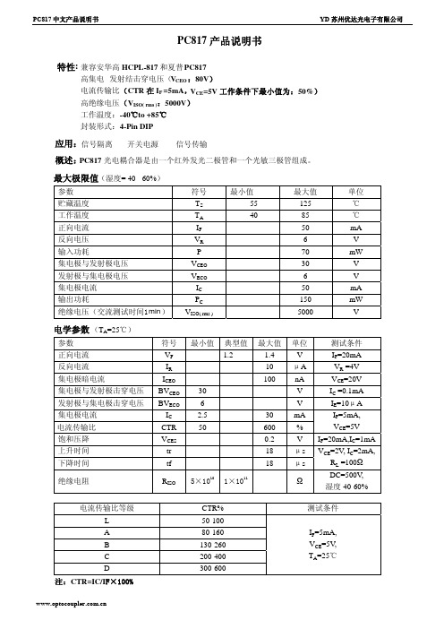
电流传输比等级 L A B C D
注:CTR=IC60 130-260 200-400 300-600
测试条件
IF=5mA, VCE=5V, TA=25℃
VCEO VECO
IC PC VISO( rms )
最小值 -55 -40
最大值 125 85 50 6 70 30 6 50 150 5000
单位 ℃ ℃ mA V mW V V mA mW V
电学参数 (TA=25℃)
参数 正向电流 反向电流 集电极暗电流 集电极与发射极击穿电压 发射极与集电极击穿电压 集电极电流 电流传输比 饱和压降 上升时间 下降时间
绝缘电阻
符号 VF IR ICEO BVCEO BVECO IC CTR VCES tr tf
RISO
最小值 典型值 1.2
30 6 2.5 50
5×10¹⁰ 1×10¹¹
最大值 1.4 10 100
30 600 0.2 18 18
单位 V μA nA V V mA % V μs μs
Ω
测试条件
IF=20mA VR =4V VCE=20V IC =0.1mA IE=10μA IF=5mA, VCE=5V IF=20mA,IC=1mA VCE=2V, IC=2mA, RL =100Ω DC=500V, 湿度 40-60%
应用:信号隔离 开关电源 信号传输
概述:PC817 光电耦合器是由一个红外发光二极管和一个光敏三极管组成。
最大极限值(湿度= 40 - 60%)
参数 贮藏温度 工作温度 正向电流 反向电压 输入功耗 集电极与发射极电压 发射极与集电极电压 集电极电流 输出功耗 绝缘电压(交流测试时间1 min )
PC817光耦
80 to 600
PC8 * 7
A, B, C, D或无标记
50 to 600
*:1或2或3或4
图1测试电路的频率响应 图2测试电路的响应时间
特性曲线图
正向电流比(常温) 集电极功耗比(常温)
峰值正向电流与占空比电流传输比比正向电流
正向电流与正向电压 集电极电流比集电极发射极电压
相对比率与电流传输比常温集电极发射极饱和电压与常温
Ω
Floating capacitance浮动电容
Cf
V = 0, f = 1MHz
-
0.6
1.0
pF
Cut-off frequency截止频率
fc
VCE = 5V, I C = 2mA, R L = 100 W, -3dB
-
80
-
kHz
Response time响应时间
Rise time上升时间
tr
-55 to + 125
℃
*3Soldering temperature焊接温度
T sol
260
℃
* 1脉冲宽度<=100ms,占空比:0.001
* 2 40至60%相对湿度,交流1分钟
* 3 10秒
Electro-optical Characteristics光电特性
Parameter参数
Symbol符号
Ct
V = 0, f = 1kHz
-
30
250
pF
输出侧
Collector dark current集电极暗电流
ICEO
VCE = 20V
-
-
10-7
A
光电耦合器pc中文资料

光电耦合器p c中文资料 The Standardization Office was revised on the afternoon of December 13, 2020光电耦合器pc817中文资料PC817光电耦合器广泛用在电脑终端机,可控硅系统设备,测量仪器,影印机,自动售票,家用电器,如风扇,加热器等电路之间的信号传输,使之前端与负载完全隔离,目的在于增加安全性,减小电路干扰,减化电路设计。
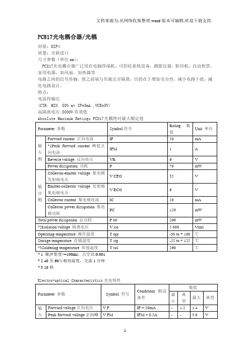
特点:电流传输比(CTR: MIN. 50% at IF=5mA ,VCE=5V)高隔离电压:5000V有效值公认的UL认证,档案编号E64380* 2 40至60%相对湿度,交流1分钟* 3 10秒Response time 响应时间Rise time 上升时间tr VCE = 2V, I C =2mA, R L = 100 W- 4 18 μs Fall time下降时间tf - 3 18 μsModel No. 型号Rank mark 等级标志电流传输比CTR ( % )PC817A A 80 to 160PC817B B 130 to 260PC817C C 200 to 400PC817D D 300 to 600PC8 * 7AB A 或 B 80 to 260PC8 * 7BC B 或C 130 to 400PC8 * 7CD C 或 D 200 to 600PC8 * 7AC A, B 或 C 80 to 400PC8 * 7BD B, C 或 D 130 to 600PC8 * 7AD A, B, C 或 D 80 to 600PC8 * 7 A, B, C, D 或无标记50 to 600图1测试电路的频率响应图2测试电路的响应时间特性曲线图正向电流比(常温) 集电极功耗比(常温)峰值正向电流与占空比电流传输比比正向电流正向电流与正向电压集电极电流比集电极发射极电压相对比率与电流传输比常温集电极发射极饱和电压与常温集电极暗电流比常温响应时间与负载电阻频率响应集电极发射极饱和电压与正向电流应用电路:图4 打开或关闭12V直流电动机的TTL控制信号输入电路图图5 与TL431配合的电源反馈电路封装尺寸及功能图:译自sharp公司。
pc817光耦工作原理(一)

pc817光耦工作原理(一)PC817光耦工作原理初探什么是PC817光耦?PC817光耦是一种常见的电子元件,通常用于隔离控制电路和负载电路。
它由一个发射器和一个接收器组成,通过光线传输信号,从而实现隔离控制。
PC817光耦的工作原理是什么?PC817光耦的工作原理基于光电效应,它通过将输入端(发射器)和输出端(接收器)隔离开来,从而防止高电压和高电流影响到控制电路。
具体来说,当输入端(发射器)电流通入时,它会产生一个光线信号,该光线会通过PC817光耦内部的隔离区域,到达输出端(接收器)。
一旦该信号到达输出端(接收器),它会引发一定的电信号,从而触发输出电路。
这样就实现了输入端和输出端之间的隔离控制。
如何使用PC817光耦?使用PC817光耦需要注意以下几点:1.确保输入端(发射器)和输出端(接收器)之间没有电线连接2.确保输入端(发射器)和输出端(接收器)之间的距离足够接近,以便光线传输3.确保输入端(发射器)和输出端(接收器)之间的电间隔符合安全标准总结PC817光耦是一种常见的电子元件,它能够隔离控制电路和负载电路,从而使电路更加安全可靠。
它的工作原理基于光电效应,需要注意输入端和输出端之间的距离和电间隔。
PC817光耦工作原理深入剖析光电效应是什么?光电效应是指材料受到光线照射时,会将光线吸收并转化为电荷的现象。
这种效应有着广泛的应用,如太阳能电池、摄像头等。
光耦的内部结构PC817光耦具有以下内部结构:1.发光二极管2.光敏二极管3.隔离区域其中,发光二极管是用于产生光线的元件,而光敏二极管则是用于接收光线并产生电信号的元件。
隔离区域则是用于隔离输入端和输出端的电气信号的区域。
光耦的工作原理详解当输入端(发射器)电流通入时,发光二极管会产生一定的光线信号。
随后,这个信号会经过隔离区域,并到达输出端(接收器)。
当光线到达输出端(接收器)时,光敏二极管会感知到光线的存在,并产生一定的电信号。
pc817
PC817简介PC817是一种光耦合器件,也被称为光耦隔离器。
它由发光二极管和光敏三极管组成,用于将电气信号从一个电路隔离到另一个电路,以保护电路免受干扰和噪声。
PC817被广泛应用于各种电子设备中,如计算机、通信设备、工业控制系统等。
它能够提供电气隔离,并实现信号的传输和调节,同时具有高隔离电压、低耦合容量和快速响应时间等特点。
结构PC817由两个部分组成:发光二极管和光敏三极管。
发光二极管(LED)是一个用于发射的光源,而光敏三极管(Phototransistor)是一个光敏探测器,用于接收光信号。
发光二极管通常采用红外LED,可以向外发射红外光。
光敏三极管结构类似于普通的三极管,但其基极区域被替换为光敏区域,可以感受到光信号并转换为电信号。
这两个部分通过一个透明的隔离垫(Isolation Barrier)分离,以实现电气隔离。
工作原理PC817的工作原理基于光电效应,其过程如下:1.当外部信号加到PC817的输入端时,输入电流通过LED流过,LED发出红外光。
2.红外光穿过隔离垫,并照射在光敏三极管的光敏区域上。
3.光敏三极管内部的光敏区域吸收红外光,并产生电流。
4.光敏电流通过光敏三极管的集电极输出到PC817的输出端,输出电流与输入电流呈线性关系。
由于发光二极管和光敏三极管之间通过隔离垫隔离,电路之间达到了电气的隔离,从而保护了接收端免受输入端的干扰和噪声。
主要特点PC817具有以下主要特点:1.高隔离电压:PC817能够提供高达2500Vrms的隔离电压,确保电路之间的安全隔离。
2.低耦合容量:PC817具有低耦合容量,减少了信号传输的时间延迟和失真。
3.快速响应时间:PC817具有快速的响应时间,适用于高速数据传输和控制应用。
4.小型封装:PC817具有小型的DIP封装,便于集成到各种电路板中。
5.高可靠性:PC817具有稳定的性能和高可靠性,适用于工业环境下的长期运行。
应用领域PC817在以下领域中得到广泛应用:1.计算机和通信设备:PC817常用于计算机主板、交换机、路由器等设备中,用于隔离和传输信号。
PC817光耦

PC817光电耦合器/光耦封装:DIP4质量:全新进口尺寸参数(单位mm):PC817光电耦合器广泛用在电脑终端机,可控硅系统设备,测量仪器,影印机,自动售票,家用电器,如风扇,加热器等电路之间的信号传输,使之前端与负载完全隔离,目的在于增加安全性,减小电路干扰,减化电路设计。
特点:电流传输比(CTR: MIN. 50% at IF=5mA ,VCE=5V)高隔离电压:5000V有效值Absolute Maximum Ratings PC817光耦绝对最大额定值Parameter 参数Symbol符号Rating 数值Unit 单位输入侧Forward current 正向电流IF50mA *1Peak forward current 峰值正向电流IFM1A Reverse voltage 反向电压VR6V Power dissipation 功耗P70mW输出侧Collector-emitter voltage 集电极发射极电压V CEO35V Emitter-collector voltage 发射极集电极电压V ECO6V Collector current 集电极电流IC50mA Collector power dissipation 集电极功耗PC150mWTotal power dissipation 总功耗P tot200mW *2Isolation voltage 隔离电压V iso 5 000Vrms Operating temperature 操作温度T opr-30 to + 100℃Storage temperature 存储温度T stg-55 to + 125℃*3Soldering temperature 焊接温度T sol260℃* 1 脉冲宽度<=100ms,占空比:0.001* 2 40至60%相对湿度,交流1分钟* 3 10秒Electro-optical Characteristics光电特性Parameter 参数Symbol 符号Conditions 测试条件数值最小典型最大典型输入侧Forward voltage正向电压V F IF = 20mA- 1.2 1.4V Peak forward voltage正向峰值电压V FM IFM = 0.5A-- 3.0V Reverse current 反向电流IR VR =4V--10μA Terminal capacitance 终端电容Ct V = 0, f = 1kHz-30250pF输出侧Collector dark current 集电极暗电流ICEO VCE = 20V--10-7ATra nsf er ch ara c-t eri sti cs 传输特点*4Current transfer ratio 电流传输比CTRIF = 5mA, V CE= 5V50-600% Collector-emitter saturationvoltage 集电极发射极饱和电压V CE(sat)IF = 20mA, I C =1mA-0.10.2VIsolation resistance 隔离电阻R ISODC500V, 40 to60% RH5x10101011-ΩFloating capacitance 浮动电容Cf V = 0, f = 1MHz-0.6 1.0pF Cut-off frequency截止频率fcVCE = 5V, I C =2mA, R L = 100W, -3dB-80-kHzResponsetime 响应时间Rise time 上升时间tr VCE = 2V, I C =2mA, R L = 100W-418μs Fall time下降时间tf-318μs* 4分类表电流传输比如下所示Model No. 型号Rank mark 等级标志电流传输比CTR ( % ) PC817A A80 to 160PC817B B130 to 260PC817C C200 to 400PC817D D300 to 600PC8 * 7AB A 或B80 to 260PC8 * 7BC B 或C130 to 400PC8 * 7CD C 或D200 to 600 PC8 * 7AC A, B 或C80 to 400 PC8 * 7BD B, C 或D130 to 600 PC8 * 7AD A, B, C 或D80 to 600PC8 * 7A, B, C, D 或无标记50 to 600*:1或2或3或4图1测试电路的频率响应图2测试电路的响应时间特性曲线图正向电流比(常温) 集电极功耗比(常温)峰值正向电流与占空比电流传输比比正向电流正向电流与正向电压集电极电流比集电极发射极电压相对比率与电流传输比常温集电极发射极饱和电压与常温集电极暗电流比常温响应时间与负载电阻频率响应集电极发射极饱和电压与正向电流。
为什么要使用PC817光耦
为什么要使用PC817光耦PC817光耦以及其参数,为其自身产品品质和品牌的建树奠定了坚实基础:1.输入参数光电耦合器的输入参数就是发光二极管的参数。
2.输出参数与所用的光电管基本相同,仅对光电流和饱和压降加以说明。
(1)光电流指光电耦合器输入一定的电流(一般为10mA)、输出端接有一定负载(约500Ω)、并按规定极性加一定电压(通常为10V)时,在输出端所产生的电流。
对于由光电三极管构成的耦合器,光电流为几毫安以上;由光电二极管构成的耦合器,则约为几十到几百微安。
(2)饱和压降UCE(sat)指在由光电三极管构成的光电耦合器中,输入一定电流(一般为20mA),输出回路按规定极性加一定电压(通常为10V),调节负载电阻,使输出电流为一定值(一般为2mA)时,光电耦合器输出的电压。
其值通常为0.3V。
3.传输参数(1)电流传输比CTR指在直流工作状态下,光电耦合器的输出电流IL与输入电流IF之比值即CTR=IL/IF,它的大小反映光电耦合器传输效率的高低。
不加复合管时,总是小于1。
(2)隔离电阻RISO指发光二极管与光电管之间的绝缘电阻,反映输入与输出之间的绝缘水平,一般为109~1013Ω。
(3)极间耐压UISO指发光二极管与光电管之间的绝缘耐压,一般都在500V以上。
不管是信号输入端还是输出端,都要注意电源电压及限流。
不要直接接电源而无负载电阻,这样要烧掉的。
6,在生活无处不在的电子行业的体现:PC817光耦自进入中国市场以来,很快成为中国顶级豪宅项目最钟爱的电源产品,是否使用品牌的电源适配器已成为衡量住宅档次和身份的象征,而PC817光耦则更是充分体现了其品位和优雅。
它的特点都有以下几点①隔离性能好,输入端与输出端完全实现了电隔离,其绝缘电阻RISO一般均能达到1010Ω以上,绝缘耐压VISO在低压时都可满足使用要求,高耐压一般能超过lkV,有的可达10kV以上。
②光信号单向传输,输出信号对输入端无反馈,可有效阻断电路或系统之间的电联系,但并不切断他们之间的信号传递。
光电耦合器pc817

光电耦合器pc817中文资料
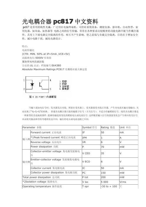
pc817是常用的线性光藕,广泛用在电脑终端机,可控硅系统设备,测量仪器,影印机,自动售票,家用电器,如风扇,加热器等电路之间的信号传输,常常在各种要求比较精密的功能电路中被当作耦合器件,具有上下级电路完全隔离的作用,相互不产生影响。
使之前端与负载完全隔离,目的在于增加安全性,减小电路干扰,减
化电路设计。
特点:电流传输比
(CTR:MIN.50%atIF=5mA,VCE=5V)高隔离电压:5000V有效值紧凑型双列直插封装
公认的UL认证,档案编号E64380
AbsoluteMaximumRatingsPC817光耦绝对最大额定值
当输入端加电信号时,发光器发出光线,照射在受光器上,受光器接受光线后导通,产生光电流从输出端输出,从而实现了"电-光-电"的转换。
普通光电耦合器只能传输数字信号(开关信号),不适合传输模拟信号。
线性光电耦合器是一种新型的光电隔离器件,能够传输连续变化的模拟电压或电流信号,这样随着输入信号的强弱变化会产生相应的光信号,从而使光敏晶体管的导通程度也不同,输出的电压或电流也
随之不同。
光耦元件PC817应用分析
光耦元件PC817应用分析光耦元件(Optocoupler)是一种将输入电信号和输出电信号进行电气隔离的器件,它由发光二极管(LED)和光敏三极管(Phototransistor)组成。
光耦元件PC817是一种常见的光耦元件,广泛应用于电源隔离、电路控制和信号传输等领域。
PC817的主要特点是:工作电流小、转速快、输出稳定、电气隔离性好。
它能够将输入电信号通过光信号传递给输出端,从而实现电气隔离,避免了因输入端和输出端之间的电流互相干扰而造成的干扰噪声。
在电源隔离方面,PC817常见于开关电源中,用于将输入端的开关信号通过光耦元件传递给控制电路,从而实现电源的开关。
它具有电气隔离性能,可以有效地隔离输入端和输出端的电源,避免了由于电源开关引起的电压干扰。
在电路控制方面,PC817可以用于替代机械继电器,实现电气隔离的继电器功能。
它的输出端具有较高的电压和电流能力,可以直接驱动电路中的负载,如电动机、灯泡等。
同时,光耦元件具有快速的响应速度,能够快速地将输入端的控制信号传递给输出端,实现对电路的精确控制。
在信号传输方面,PC817可以用于隔离输入端和输出端的信号,避免了信号干扰和波形畸变。
它能够将输入端的模拟信号或数字信号转换成光信号并传递给输出端,保证了信号的传输质量。
在工业自动化控制系统中,PC817可以广泛应用于PLC控制、DCS系统、传感器输出等信号隔离和传输的场景中。
此外,PC817还具有体积小、价格低廉、可靠性高等特点,可以满足不同应用场景的需求。
它广泛应用于电子设备、通信设备、仪器仪表、家电、机械控制和汽车电子等领域。
总结起来,光耦元件PC817是一种常见的光耦元件,应用广泛,主要用于电源隔离、电路控制和信号传输等领域。
它具有工作电流小、转速快、输出稳定、电气隔离性好的特点,可以有效地隔离输入端和输出端的电源和信号,保证了电路的稳定性和可靠性。
PC817光耦的作用原理
PC817光耦的作用原理PC817光耦是一种集光电转换功能于一体的电子元件,主要由发光二极管和光敏三极管组成。
它的基本作用是实现输入与输出的电气隔离,将输入端与输出端之间的信号传输通过光线完成,从而保证高压直流电路与低压直流电路之间的隔离与连接。
光耦的基本结构PC817光耦由发光二极管(LED)和光敏三极晶体管(光控三极管)组成。
LED作为光源,当输入端施加电压时,LED发出光信号;光信号经过隔离区域作用于光敏三极晶体管,使其内部产生光电流,从而控制输出端的电流及电压。
工作原理1.输入信号传输:当输入端施加电压时,LED发出光信号,光信号穿过隔离区域,作用于光敏三极晶体管的发射区,使其导通。
2.光电转换:光敏三极晶体管的发射区被光信号照射后,产生光电流,使其变成一个有效的电流源。
3.输出信号控制:光电流通过输出端的负载电路,从而控制输出端的电流和电压,实现对电路的隔离与控制。
应用领域PC817光耦广泛应用于各类电子设备中,主要用于实现高低电压之间的隔离、信号传输与电源控制。
典型应用包括: - 家用电器:如电视、空调等,在开关控制电路中实现信号隔离与控制。
- 工业自动化:用于PLC控制系统、传感器信号隔离及调节等。
- 通信设备:如光纤通信、路由器等,确保电路之间的隔离与稳定性。
优势与特点1.隔离性好:通过光信号传输,可实现高效的电气隔离,提高电路之间的安全性。
2.体积小:PC817光耦体积小巧,适用于电路板空间有限的场合。
3.可靠性高:光电器件无机械触点,寿命长,抗干扰能力强。
4.响应速度快:由于光信号传输速度快,PC817光耦具有较高的响应速度。
结语总的来说,PC817光耦作为一种重要的电子元件,在现代电子技术领域有着广泛的应用。
通过光信号的传输,实现了输入与输出之间的隔离与控制,提高了电路的安全性和稳定性,为各类电子设备的运行提供了可靠保障。
希望通过本文的介绍,读者能更好地了解PC817光耦的原理与应用。
817c光耦中文资料介绍

817c光耦中文资料介绍光耦合器(opticalcoupler,英文缩写为OC)亦称光电隔离器或光电耦合器,简称光耦。
它是以光为媒介来传输电信号的器件,通常把发光器(红外线发光二极管LED)与受光器(光敏半导体管)封装在同一管壳内。
当输入端加电信号时发光器发出光线,受光器接受光线之后就产生光电流,从输出端流出,从而实现了“电—光—电”转换。
以光为媒介把输入端信号耦合到输出端的光电耦合器,由于它具有体积小、寿命长、无触点,抗干扰能力强,输出和输入之间绝缘,单向传输信号等优点,在数字电路上获得广泛的应用。
光耦817c引脚及功能PC817C是光隔离线性反馈控制器件,是PC817系列中常用的一个型号。
左边(1、2脚:输入端、控制端)是一个发光二极管。
右边(3、4脚:输出端、受控端)是一个三极管(CE极)。
控制端与受控端是隔离的。
光耦817c的应用光耦817c应用广泛,主要应用于电源设备上,隔离高低电压的用途。
相关的终端产品应用包括家电、温控、冷气空调(HVAC)、贩卖机、照明控制装置、充电器与交换式的电源供应器。
电路之间的信号传输,使之前端与负载完全隔离,目的在于增加安全性,减小电路干扰,减化电路设计。
通过增加光敏基极正反馈来提高光耦的开关速度817c光耦怎么测好坏方法:用数字万用表的PN结测量端,红表笔“电池+极”接光耦的“1”端,黑表笔“电池-极”接光耦的“2”端(即使光耦的发光二极管正向导通),用另一电表测量“3”“4”端电阻,断开或接通输入端(发光二极管端),输出端电阻应有大幅度变化,说明改光耦是好的。
另发光二极管端万用表可用电池串限流电阻代替。
817c光耦的作用817c是光耦,对输入、输出电信号起隔离作用,光耦合器一般由三部分组成:光的发射、光的接收及信号放大。
输入的电信号驱动发光二极管(LED),使之发出一定波长的光,被光探测器接收而产生光电流,再经过进一步放大后输出。
这就完成了电—光—电的转换,从而起到输入、输出、隔离的作用。
pc817应用电路实例
PC817应用电路实例引言P C817是一种常用的光耦合器件,广泛应用于电子电路中。
它具备隔离、放大、传输和控制信号等功能,可用于多种电路应用。
本文将介绍几个常见的PC817应用电路实例,并对其工作原理进行简要解析。
1.电压比例器电路电压比例器电路是PC817常见的应用之一。
该电路用于将输入电压转换为与输入电压成比例的输出电压。
其中,P C817作为光耦合器件,将输入电压光耦合到输出侧,实现电气隔离。
1.1电路图+--------+V i n----+--->||||PC817|----Vo ut+--->||+--------+1.2工作原理输入电压Vi n经过限流电阻限制电流,通过发射器端将光信号发送给接收器端。
接收器端根据光强度的变化来控制输出电流,输出端的电压V o ut即与输入电压成比例。
2.断电报警电路断电报警电路是另一种常见的PC817应用。
该电路用于监测输入电源是否正常工作,并在电源断电时触发报警。
2.1电路图+--------+V c c----+----->||+----->|PC817|----Al ar m|||+------>|||+--------+|G N D---+2.2工作原理在正常工作状态下,输入电源Vc c提供电压给P C817。
通过光电传感器将信号传递给输出端,输出端接通报警器,发出报警信号。
当输入电源断电时,PC817无光信号输入,输出端断开,报警信号停止。
3.脉冲发射电路P C817还可以用于脉冲发射电路中。
该电路用于产生干净的脉冲信号,可应用于遥控器、遥感器等领域。
3.1电路图+--------+V i n--+--->||||PC817|--->Pu lse O ut|||G N D--+--->||+--------+3.2工作原理输入脉冲信号Vi n通过限流电阻限制电流,经过光电传感器的发射端发送光信号。
pc817应用电路实例
pc817应用电路实例一、PC817简介PC817是一种常用的光电耦合器,具有体积小、传输速率快、抗干扰能力强等优点。
在其内部,包含一个光电二极管和一个光电三极管,通过光电效应实现电信号的传输。
下面简要介绍其基本参数和工作原理。
1.基本参数- 工作电压:3~5V- 工作温度:-40℃~85℃- 输出电流:10mA- 输入电流:1mA- 隔离电压:2500V2.工作原理PC817的光电二极管在光照条件下,产生光电流,经过光电三极管放大后,输出给负载。
当输入端的光信号消失时,输出端无电流输出,从而实现光电隔离。
二、PC817应用电路实例下面介绍四个PC817应用电路实例,包括电压监控电路、电流检测电路、温度控制电路和无线通信电路。
1.电压监控电路电压监控电路用于实时监测电源电压,并通过PC817输出光电信号。
当电压超出设定范围时,输出端产生光信号,警示系统采取相应措施。
2.电流检测电路电流检测电路通过PC817实现电流测量,并将测量结果转换为光信号输出。
可用于检测负载电流,确保系统工作在正常范围内。
3.温度控制电路温度控制电路利用PC817进行温度监控,当温度超过设定值时,输出光信号,控制系统启动散热措施。
4.无线通信电路无线通信电路采用PC817实现电信号与光信号的转换,用于实现远程无线监控和控制。
三、电路设计与调试1.设计步骤(1)根据应用需求选择合适的PC817型号。
(2)确定输入、输出端口电路,如电阻、电容等。
(3)设计光电耦合器的驱动电路,如电压、电流调整。
(4)设计负载电路,确保输出光信号能满足负载需求。
2.调试方法(1)搭建电路,连接电源、输入信号和负载。
(2)通过示波器、万用表等仪器检测电路工作状态。
(3)调整电路参数,使系统工作在最佳状态。
四、PC817应用注意事项1.电源选择:根据实际需求选择合适的电源电压,注意电源电压应稳定,以免影响光电耦合器的性能。
2.信号输入输出配置:输入信号应满足PC817的输入电流要求,输出信号需考虑负载需求。
pc817封装尺寸
pc817封装尺寸PC817是一种常用的光耦合器件,其封装尺寸对于使用者非常重要。
本文将详细介绍PC817的封装尺寸,以帮助读者更好地了解和使用该器件。
一、PC817简介PC817是一种双极性输出型光耦合器件,常用于电气隔离和信号传输等应用场合。
它由发光二极管(LED)和光敏三极管(光敏三极管)两部分组成,能够将输入信号转换成光信号,实现对输入信号的隔离和放大。
二、PC817的封装类型PC817采用多种封装类型,其中最常见的是DIP(双列直插)封装和SMD(表面贴装)封装。
不同封装类型的PC817尺寸略有不同,下文将分别介绍这两种常见封装的尺寸。
1. DIP封装PC817的DIP封装,也称为PDIP(塑料双列直插)封装,是一种传统的封装方式。
它采用了直插式引脚,方便焊接和插拔操作。
常见的DIP封装类型有PDIP-4、PDIP-6、PDIP-8等。
PDIP-4封装的PC817尺寸为:- 长度(L):6.5mm- 宽度(W):4.6mmPDIP-6封装的PC817尺寸为:- 长度(L):11.6mm- 宽度(W):6.5mm- 高度(H):4.4mmPDIP-8封装的PC817尺寸为:- 长度(L):13.2mm- 宽度(W):6.5mm- 高度(H):4.4mm2. SMD封装PC817的SMD封装,即表面贴装封装,是一种现代化的封装方式。
它主要应用于SMT(表面贴装技术)制造的电路板上。
常见的SMD封装类型有SOIC-4、SOIC-6、SOIC-8等。
SOIC-4封装的PC817尺寸为:- 长度(L):3.8mm- 宽度(W):3.8mm- 高度(H):1.6mmSOIC-6封装的PC817尺寸为:- 宽度(W):3.9mm- 高度(H):1.9mmSOIC-8封装的PC817尺寸为:- 长度(L):5.8mm- 宽度(W):4.0mm- 高度(H):1.9mm三、总结PC817是一款常见的光耦合器件,广泛应用于电气隔离和信号传输等领域。
pc817工作原理

pc817工作原理
PC817是一种光电隔离器件,用于将电气信号隔离开来,保护电路的稳定性和安全性。
PC817的工作原理如下:
1. 光源发出光:PC817由一个发光二极管(LED)作为光源。
当对LED施加正向偏置电压时,电流通过LED并且LED发
出光。
2. 光电二极管接受光:PC817的另一半部分是一个光电二极管(Phototransistor)。
当LED发出的光照射到光电二极管上时,LED光激发光电二极管中的电子,使其产生导电能力。
3. 信号隔离:PC817的光电二极管和LED通过一个透明的隔
离层彼此分隔着,这样电气信号就不会直接通过电路连接。
相反,当光照射到光电二极管上时,光电二极管中的导电能力会影响其输出端的电流。
4. 放大与转换:PC817的光电二极管中的电流会被连接的电路或器件接收并进行进一步处理。
这个电路或器件可以是放大器、转换器、继电器等,它们会根据光电二极管的输出电流产生相应的输出信号。
总结:PC817通过光的照射来实现电气信号的隔离与传输。
当接收到光照射时,光电二极管中的电流变化,从而影响到
PC817连接的电路或器件的工作状态。
这种光电隔离原理可以
有效地防止电路间的电气干扰和噪声,提供电路保护与信号传输的作用。
pc817工作原理

pc817工作原理
PC817是一款光耦合器件,其工作基于光电耦合效应。
该器件由一个发光二极管(LED)和一个光敏三极管(光导电晶体管)组成。
当电流通过LED时,LED会发出红外光。
这个红外光会被传
输到光敏三极管的发射端,并被其接收。
在光敏三极管的收集端,有一个接收电流的电路。
当光照到光敏三极管的收集端时,会产生一个基极电流。
根据基尔霍夫电流定律,这个基极电流会通过光敏三极管的发射端,形成一个与LED上的输入电流
相对应的输出电流。
通过这种方式,PC817将输入端的电流转换为输出端的光电流。
由于输出电流和输入电流之间没有物理连接,因此可以实现电气隔离。
这使得PC817成为一种常用的电气隔离解决方案。
它可以在工业控制、自动化设备和电源等应用中起到隔离和信号传输的作用。
需要注意的是,PC817还具有输出器件与输入器件之间的电压隔离。
输出器件和输入器件之间存在一个漏电流路径,确保了电压隔离。
这是通过内部电路的设计实现的,以确保输出端能够与输入端隔离,从而满足特定应用中的安全和保护要求。
总之,PC817工作原理基于光电耦合效应,将输入电流转换为输出光电流实现电气隔离。
它是一种常用于工业控制和电源等领域的器件。
pc817应用电路实例
pc817应用电路实例
PC817是一种光耦合器件,常用于隔离输入与输出、信号传输、电气隔离等应用。
以下是PC817的几个应用电路实例:
1. 隔离输入与输出:PC817可用于将输入信号与输出信号进行电气隔离,以保护输入与输出电路的稳定性和安全性。
例如,可以将一个外部开关连接到PC817的输入端,将输出端连接
到微控制器的输入端,实现电气隔离并检测开关状态。
2. 逻辑电平转换:PC817可用作逻辑电平转换器,将低电平信号转换为高电平信号或相反。
例如,可以将
3.3V的逻辑信号
输入到PC817的输入端,通过光耦合器件的输出端输出转换
后的5V逻辑信号,以实现不同电平之间的信号转换。
3. 继电器驱动:PC817可用于驱动继电器,实现对电路的开关控制。
例如,将PC817的输出端连接到继电器的控制端,通
过输入控制信号来驱动继电器的开关动作,从而实现对具有较高电流或电压要求的设备或电路的控制。
4. 电压/电流检测:PC817可用于检测电路中的电压或电流值,并输出与之相对应的信号。
例如,将PC817的输入端连接到
待测电路的电压或电流测量点,通过光耦合器件的输出端输出检测到的电压或电流值。
总之,PC817作为一种常用的光耦合器件,其应用范围广泛,可以用于电气隔离、信号传输、电路输入与输出、电压/电流
检测等各种电路应用中。
以上仅为一些基本的应用电路实例,具体应用仍需根据实际需求进行设计和调整。
PC817 系列规格书

1. 计算机终端. 2.系统装置, 测量仪器. 3.寄存器, 复印机, 自动售货机. 4.家用电器, 比如风扇、热水器等等.
5. 高低电压电路间的电气隔绝和信号传输.
页数 1 /10
● 外形尺寸 典型的直插模式
两位周期码 两位公历年码
分类码 正极标示
M 直插模式
两位周期码 两位公历年码
分类码 正极标示
20min 20min
0/20
循环次数:20cycle
温度:260℃;
时间:10±1seconds.
0/20
温度:235℃;
时间:5±1seconds.
0/20
● 信赖度失效之判断标准
符号
VF (V) Ir(uA) CTR(%) VCE(sat) BVCEO BVECO
测试条件 If=50mA Vr=5V If=5mA, VCE=5V IF=20mA, IC= 1mA IC=0.1mA, IF=0 IE=10μA, IF=0
测试时间:1,000hrs
0/20
低温:-55℃±5℃
测试时间:1,000hrs
0/20
压强:15PSIG;温度:121℃
湿度:100%;
0/20
测试时间:48hrs
125℃ ~ 25℃ ~ -55℃ ~ 25℃
30min 5min 30min 5min 0/20 循环次数:20cycle
125℃ ~-55℃
Ic CTR
饱和电压
VCE(sat)
绝缘电阻
Riso
电容
Cf
截至频率
fc
反应时间(上升)
tr
反应时间(下降)
tf
测试条件
最小值 典型值 最大值 单位
PC817中文详细资料
T sol
260
℃
Symbol Conditions 测试条
数值
符号 件
最小 典型 最大 典型
Forward voltage 正向电压 V F IF = 20mA
-
1.2 1.4 V
输入侧
Peak forward voltage 正向峰
值电压
V FM IFM = 0.5A
-
Reverse current 反向电流 IR
B 或C
130 to 400
C或D
200 to 600
A, B 或 C
80 to 400
B, C 或 D
130 to 600
A, B, C 或 D
80 to 600
A, B, C, D 或 无标记 50 to 600
图 1 测试电路的频率响应 特性曲线图
图 2 测试电路的响应时间
正向电流比(常温)
集电极功耗比(常温)
峰值正向电流与占空比
电流传输比比正向电流
正向电流与正向电压
集电极电流比集电极发射极电压
相对比率与电流传输比常温
集电极发射极饱和电压与常温
集电极暗电流比常温
响应时间与负载电阻
频率响应
集电极发射极饱和电压与正向电流
应用电路:
图 4 打开或关闭 12V 直流电动机的 TTL 控制信号输入电路图 图 5 与 TL431 配合的电源反馈电路
光电耦合器 pc817 中文资料
pc817 是常用的线性光藕,广泛用在电脑终端机,可控硅系统设备,测量仪器,影印机,自动售票,家 用电器,如风扇,加热器等 电路之间的信号传输,常常在各种要求比较精密的功能电路中被当作耦合器 件,具有上下级电路完全隔离的作用,相互不产生影响。使之前端与负载完全隔离,目的在于增加安全 性,减小电路干扰,减化电路设计。
- 1、下载文档前请自行甄别文档内容的完整性,平台不提供额外的编辑、内容补充、找答案等附加服务。
- 2、"仅部分预览"的文档,不可在线预览部分如存在完整性等问题,可反馈申请退款(可完整预览的文档不适用该条件!)。
- 3、如文档侵犯您的权益,请联系客服反馈,我们会尽快为您处理(人工客服工作时间:9:00-18:30)。
FOD814 Series, FOD617 Series, FOD817 Series 4-Pin Phototransistor Optocouplers
1
FOD814 Series, FOD617 Series, FOD817 Series Rev. 1.0.2
FOD814 Series, FOD617 Series, FOD817 Series 4-Pin Phototransistor Optocouplers
15
*Typical values at TA = 25°C
Typ* —
Max Unit 300 % 150 80 125 200 320
— 600 — 160 — 260 — 400 — 600 0.1 0.2 V — 0.4 0.1 0.2 80 — KHz
3 FOD814 Series, FOD617 Series, FOD817 Series Rev. 1.0.2
TSTG TOPR TSOL P TOT
-55 to +150
-55 to +105
-55 to +110
260 for 10 sec
200
Continuous Forward Current Reverse Voltage Power Dissipation
Derate above 100°C
IF
FOD617A: 40–80%
FOD817: 50–600%
FOD617B: 63–125%
FOD817A:80–160%
FOD617C: 100–200% FOD817B: 130–260%
FOD617D: 160–320% FOD817C:200–400%
FOD814: 20–300%
FOD817D:300–600%
Electrical/Characteristics (TA = 25°C Unless otherwise specified.)
Individual Component Characteristics
Parameter
Device Test Conditions Symbol Min Typ* Max Unit
EMITTER
Forward Voltage Reverse Leakage Current Terminal Capacitance
FOD814
(IF = ±20 mA)
VF
FOD617
(IF = 60 mA)
FOD817
(IF = 20 mA)
FOD617
(VR = 6.0 V)
IR
FOD817
FOD814 Series, FOD617 Series, FOD817 Series 4-Pin Phototransistor Optocouplers
November 2005
FOD814 Series, FOD617 Series, FOD817 Series 4-Pin Phototransistor Optocouplers
Features
■ AC input response (FOD814 only)
■ Applicable to Pb-free IR reflow soldering
■ Compact 4-pin package
■ Current transfer ratio in selected groups:
IF = ±20 mA, IC = 1 mA IF = 10 mA, IC = 2.5 mA
VCE (sat) — —
FOD817
IF = 20 mA, IC = 1 mA
—
Cut-Off Frequency FOD814 VCE = 5 V, IC = 2 mA, RL = 100 Ω, -3dB fC
Functional Block Diagram
ANODE, CATHODE 1
4 COLLECTOR
ANODE 1
4 COLLECTOR
CATHODE, ANODE 2
3 EMITTER
CATHODE 2
3 EMITTER
4
FOD814
FOD617/817
1
©2005 Fairchild Semiconductor Corporation
AC Characteristic Response Time (Rise)
Device
FOD814 FOD617 FOD817
Test Conditions
Symbol Min
VCE = 2 V, IC = 2 mA, RL = 100 Ω2
tr
—
Response Time (Fall)
FOD814 FOD617 FOD817
—
—
100 nA
—
1
100
—
1
50
—
—
100
Collector-Emitter Breakdown Voltage
Emitter-Collector Breakdown Voltage
FOD814 (IC = 0.1 mA, IF = 0) BVCEO
70
—
—
V
FOD617 (IC = 100 µA, IF = 0)
70
—
—
FOD817 (IC = 0.1 mA, IF = 0)
70
—
—
FOD814 (IE = 10 µA, IF = 0) BVECO
6
—
—
V
FOD617 (IE = 10 µA, IF = 0)
7
—
—
FOD817 (IE = 10 µA, IF = 0)
6
—
—
Transfer Characteristics (TA = 25°C Unless otherwise specified.)
(VR = 4.0 V)
FOD814 (V = 0, f = 1 kHz)
Ct
FOD617 (V = 0, f = 1 kHz)
FOD817 (V = 0, f = 1 kHz)
—
1.2
1.4
V
— 1.35 1.65
—
1.2
1.4
— 0.001 10
µA
—
—
10
—
50
250 pF
—
30
250
—
30
250
±50
50
VR
—
6
PD
70
1.7
DETECTOR
Collector-Emitter Voltage Emitter-Collector Voltage
VCEO VECO
70
6
6 (FOD817)
7 (FOD617)
Continuous Collector Current
Collector Power Dissipation Derate above 90°C
FOD814 Series, FOD617 Series, FOD817 Series 4-Pin Phototransistor Optocouplers
Transfer Characteristics (continued) (TA = 25°C Unless otherwise specified.)
DC Characteristic Device
Test Conditions
Symbol Min
Current Transfer Ratio
FOD814 FOD814A
IF = ±1 mA, VCE = 5 V1
CTR
20
50
FOD617A
IF = 10 mA, VCE = 5 V1
40
FOD617B
FOD817
Isolation Capacitance
FOD814
FOD617
FOD817
Test Conditions Symbol f = 60Hz, t = 1 min VISO
Min 5000
VI-O = 500 VDC
RISO
5x10¹⁰
VI-O = 0, f = 1 MHz
CISO
Typ* 1x10¹¹
63
FOD617C
100
FOD617D
160
FOD617A
IF = 1 mA, VCE = 5 V1
13
FOD617B
22
FOD617C
34
FOD617D
56
FOD817
IF = 5 mA, VCE = 5 V1
50
FOD817A
80
FOD817B
130
FOD817C
200
FOD817D
300
Collector-Emitter FOD814 Saturation Voltage FOD617
FOD814A: 50–150%
■ C-UL, UL and VDE approved
■ High input-output isolation voltage of 5000Vrms
■ Higher operating temperatures (versus FODXXX counterparts)
IC
50
PC
150
2.9
Units
°C °C °C mW
mA
mW mW/°C
V Vபைடு நூலகம்
mA mW mW/°C
2 FOD814 Series, FOD617 Series, FOD817 Series Rev. 1.0.2
