爱普生投影机CB-595Wi演示
爱普生投影机让您无线分享高清信号 观察爱普生最新推出的多媒体液晶工程投影系列,带来哪些启发?

爱普生投影机让您无线分享高清信号观察爱普生最新推出的多媒体液晶工程投影系列,带来哪些启发?作者:暂无来源:《中国商人》 2011年第7期伴随着工程投影市场竞争加剧,之前依靠亮度与指标竞争的工程投影市场已经慢慢地改变了策略,依靠功能、体验、差异化特点以及创新应用的全新工程投影产品已经悄然给市场注入了更多活力。
工程投影市场爆发式增长的背后也迫使厂商之间的竞争更加白热化,如何在同质化的产品中找准切入点并取得优势,已经成为每个厂商必须解决的难题。
爱普生在工程投影领域有着不俗的市场地位,在工程投影市场产品类型逐渐细分的大环境之下,爱普生强势推出旗下4款CB-1985WU系列入门级3LCD工程投影机,该系列入门级工程投影机内置无机液晶面板,可呈现高色彩亮度输出的高品质影像,显示的画质清晰、明亮、自然。
该系列入门工程投影机专门为会议过程优化,采用先进的Screen Mirroring高清无线投影方式,省去了复杂线缆的连接,可以在会议过程轻松分享手机、平板电脑、PC的屏幕图像,实现高清投影。
这4款产品精准的市场定位不但弥补了爱普生工程投影机产品线中的空白,在工程投影市场也称得上是标新立异。
诸多无线功能集一身,连接简单EPSON CB-1985WU是爱普生最新推出的多媒体液晶工程投影系列中的—款,该系列—共4款产品,突出高亮、高清、高画质与无线连接功能,是面向会议室与高端教学应用的很好选择。
爱普生CB-1985WU系列内置WiDi模块,支持IntelWiDi/Wi-i Certified Miracast技术。
Intel WiDi(lntelWirelessDisplay)全称为无线高清技术。
Wi-Fi CertifiedMiracast采用的技术由来自Wi-Fi Alliance移动和客户电子制造商和芯片制造商的团队研发,以实现简化视频分享的标准化。
根据Wi-Fi Alliance显示规格,产品包含了Miracast厂商间不同品牌的交互操作,使用户可以轻松在办公室享受大屏幕上的视频。
爱普生投影机经销商大会召开

爱普生投影机经销商大会召开作者:来源:《信息化视听》2012年第05期4月19日,在北京中家鑫园温泉酒店,爱普生隆重举办了投影机新品展览会,对高清被动立体投影方案、三通道融合方案、便携式投影机等产品和技术进行了全方位的展示。
高清被动立体投影方案呈现精彩立体效果:该方案配备了2台爱普生专业级工程投影机、1套3D摄像机、1套180英寸16:10的高增益立体投影幕、1套立体成像系统和立体眼镜若干,将3D摄像机拍摄的3D视频信号分为两路,通过HD-SDI线分别传输到两台垂直叠加的EB-Z9750WU同时投影一幅影像。
一台EB-Z9750WU投影右眼影像,一台EB-Z9750WU投影左眼影像。
两台EB-Z9750WU采用不同的极化方向,再通过被动立体眼镜左右眼的线形偏振极化镜片实现3D立体投影效果。
200英寸大屏幕投清晰呈现大屏幕画面:该投影方案使用的EBZ9900是爱普生投影系列最亮的工程投影机,具有10,000流明的输出亮度。
可以投射出200英寸的大尺寸图像,在大型会场、展会等场合中能够使参会人员清晰地看到投影内容。
内置几何校正功能和大屏幕拼接系统,无需其他软件即可实现大屏幕拼接投影。
使用爱普生原创水晶高清技术的液晶面板,提高了投影机的对比度;再加上电影滤镜技术和超级解像度技术的使用,使这款投影机具有高质量的画面表现。
投影机的双灯配置保障了投影机的连续工作。
爱普生无机液晶面板和原创的珀尔帖主动液体冷却系统,提高了投影机的使用寿命和稳定性。
150英寸大屏幕投影方案操控更加灵活:150英寸大屏幕投影方案配有1台EB-C765XN中高端商务教育投影机和1块3.05米×2.29米屏幕。
EB-C765XN中高端商务教育投影机具有5,000流明的高亮度,可无线连接iPad、iPhone、iTouch等苹果设备。
适用于大型会议室、环境明亮的会议场所、大型教堂等。
超短焦互动投影方案实现无PC互动:超短焦投影机EB-CU610Wi利用超短距离投影获得大画面,解决了普通投影机存在的光线刺眼,阴影干扰等问题。
EPSON CB—X25
EPSON CB—X25作者:张越来源:《个人电脑》2014年第03期在我们所测试过的投影机产品中,商教类投影机是比较多的。
很多厂商的投影机产品线都会将商用投影机和教育用投影机分为一类,也就是常说的商教用途投影机。
但是爱普生针对教育环境中使用投影机的特点,推出了很多转为教学用途量身定做的产品,CB-X25就是其中最新发布的一款。
CB-X25的标称亮度达到了3500流明,这就意味着即便在环境光线较为明亮的教室中,这款投影机也可以投射出150英寸的明亮画面,保证所有的学生都可以看到清晰的画面。
CB-X25采用的仍是3LCD技术,投射150英寸画面所需距离为4.3米。
由于配备了阶梯校正功能,CB-X25在安装时不必苛求完全对正屏幕,在水平正负30度范围内都可以通过水平阶梯校正滑钮来获得清晰标准的投影画面。
垂直校正则是自动方式工作,其范围也同样是正负30度。
除了明亮的展示效果和简便的安装方式,能为课堂增添活力的投影机在教育信息化的环境下更为实用。
CB-X25支持多PC投影,只需将投影机接入教学网络中,通过免费EasyMPMultiPCProjection软件就能实现四路信号的同屏显示,信号源方面,最多支持50个PC 或者安装了EpsoniProjection的智能手机或平板电脑同时接入,教师可以任选1-4路信号源进行呈现。
教师通过控制投影输出,就能充分调动学生展示热情,让课堂充满活力和创意。
在教学过程中,如果是比较大面积的教室中需要为学生展示实物焦距,就可以通过CB-X25连接实物展台进行实物演示,而且其连接也非常方便,只需一根数据线就可以完成。
CB-X25除了提供了HDMI、VGA等常见视频输入端口,还可以通过LAN进行网络投影,而最为方便使用的则是USB三合一投影功能。
不需要任何视频线缆,通过USB线缆就可以实现图像、声音的同时传输。
如果你在投影过程中需要更好的声音播放效果,CB-X25也提供了音频输出端口来连接音响设备。
爱普生CB-595Wi投影仪

爱普生CB-595Wi投影仪佚名【期刊名称】《办公自动化(办公设备与耗材)》【年(卷),期】2016(000)001【总页数】1页(P19-19)【正文语种】中文智慧教育离不开智慧校园和智慧课堂。
爱普生CB-595Wi超短焦互动投影仪全新的投影方式更灵活,用户可以把投影机放置在桌面上,不需要安装吊架也能轻松获得大画面。
桌面垂直放置投影技术改变传统投影方式,配套专业桌面投影用吊架,充分利用空间满足小课堂教学需求,让学习、讨论、互动更轻松。
爱普生CB-595Wi投影机标配两支电子笔,能够支持两个人同时进行书写或标注,彼此不会产生干扰和延迟。
同时充分考虑老师和学生的使用习惯,新增加侧面按钮和手指触控功能,快速实现写字和橡皮擦模式的切换,并实现在投影屏幕上随心拖动图片、放大缩小和书写批注,流畅的触控体验让教学更生动高效。
爱普生CB-595Wi超短焦互动投影机拥有完美的图像效果,3300流明的亮度,老师不需要在黑暗的环境中就可以清晰的演示投影图像,短焦技术有效避免了投影图像的桶形失真,画面边角更锐利,演示效果更好。
在互联网+时代,多媒体技术的不断革新起着重要作用。
研究表明,多数教师在技术接受度、技术能力和技术整合课堂教学能力三个维度的投入有限。
为了让教师把更多精力投入教学和学生,不为硬件设备而烦恼,爱普生CB-595Wi超短焦互动投影机更加高效便捷,无需安装驱动,直接支持墙面、黑板、普通白板的自动校准功能。
改变了传统必须连接电脑才能使用互动功能的限制,原创设计支持无电脑连接也可实现互动,让教学和互动更高效。
丰富的接口能够满足多种设备连接需求,轻松实现高清视频的传输。
智慧校园建设是中长期系统性工程,多媒体教室的建设中校长们不仅考虑高效便捷,还需考虑节约成本。
爱普生CB-595Wi投影机ECO模式下灯泡使用时间可达到近6000小时,降低了需要频繁更换灯泡的使用成本,更具竞争力。
爱普生 EB-455Wi EB-465i 超短焦数码投影仪 用户手册说明书

EB-455Wi
EB-465i
RGB 光阀式液晶投影系统
投影距离
EB-455Wi(WXGA)
16:10屏幕
最近端(广角)
从镜头中心到屏幕上端的距离
使用单片DLP 技术制造的投影机
使用3LCD 液晶技术制造的投影机多媒体液晶投影机
/
481 mm
369 mm
互动笔笔盒
接口丰富
全新的超长寿命过滤网
演讲者不会受到投射光线的干扰
演讲者站在屏幕前,不会受到眩目的投射光线干扰而影响避免演讲者身体阻挡投影光线
演讲者的身影不会阻挡投影机的播放,保证授课及会议的顺利进行。
扬声器,完全可以满足教学
建议消费者选购高色彩亮度并且色彩亮度和亮度(白色亮度)相等的投影机。
普通短焦投影机
普通短焦投影机EB-455Wi/465i
EB-455Wi/465i 色彩亮度1000流明
色彩亮度2200流明
多媒体液晶投影机
/
*桌面投影模式所需架子需另行购买。
DLP投影机用户手册说明书

版权本出版物(包括所有照片、插图和软件)受国际版权法律的保护,保留所有权利。
未经作者书面同意,不得复制本手册及其包含的任何资料。
© 版权2022免责声明本文档中的信息如有变更,恕不另行通知。
制造商对于本文档中的内容不提供任何表述或担保,特别放弃对于适销性或特定用途适用性的任何隐含担保。
制造商保留修订本出版物和不定期更改本文档内容且无须向任何人通知此类修订或更改的权利。
商标Kensington 是 ACCO Brand Corporation 的美国注册商标,并已在其它国家(地区)注册或正在申请注册。
HDMI、HDMI标识、以及High-Definition Multimedia Interface是HDMI Licensing LLC在美国和其他国家(地区)的商标或注册商标。
MHL、HDMI标识、以及Mobile High-Definition Link是MHL licensing, LCC的商标或注册商标。
HDBaseT™和HDBaseT Alliance标志是HDBaseT Alliance的商标。
本手册中使用的所有其他产品名称分别是其各自所有者的资产,并得到公认。
版本:1DLP投影机 – 用户手册重要安全信息重要:强烈建议您在使用投影机之前仔细阅读此部分。
这些安全和使用说明可确保您安全地使用投影机许多年。
妥善保管本手册,以备日后参考。
使用的符号机器和本手册中使用的警告符号旨在提醒您危险情形。
本手册使用下面的样式来提醒您重要信息。
注意:在主题旁边提供主题的附加信息。
重要:提供不应忽视的附加信息。
小心:提醒您可能损坏机器的情形。
警告:提醒您可能损坏机器、造成危险环境或导致人员受伤的情形。
在整部手册中,OSD 菜单中的组件部分和项目以粗体显示,如此例所所示:“按遥控器上的Menu按钮打开主菜单。
”一般安全信息请勿打开机壳。
机器内没有用户可维修的部件。
如需维修,请与有资质的维修人员联系。
爱普生商务投影机对比度全面升级

龙源期刊网
爱普生商务投影机对比度全面升级
作者:
来源:《数码世界》2008年第12期
爱普生公司最新发布的商务投影机,有一个颇为引人注意的亮点是,这些新款商务投影机的对比度都提升至了2000:1。
面对越来越普及的商务投影演示,要想在这个市场中立于不败之地,没有一点“硬功夫”是不行的。
爱普生不断提升3LCD液晶技术,面对商用用户的实际需求,将新品商务机的对比度全面提升,致力于帮助用户实现商业成功。
爱普生(中国)有限公司VD销售推进部副部门经理夏季生先生表示:“我们全面升级爱普生商务投影机的对比度,就是希望能够真正满足目前用户在进行商务演示时的多媒体应用需要。
”据了解,在此次发布的新品中,无论是入门级的EB-S6、EB-X6,还是中高端的EB-1720、EB-1725,都能够实现2000:1的对比度,此外,爱普生公司首次发布的3款宽屏投影机产品EB-W6、EB1730W、EB-1735W,在同样在实现2000:1对比度的基础上,还希望以宽屏的分辨率来进一步迎合对多媒体应用要求较高的用户,而部分配备了大功率扬声器的投影机产品,更能免除用户在进行视频播放时还需另接音箱的麻烦。
作为中国乃至全球投影机市场的领导者,爱普生公司一直致力于从用户的实际需求出发,并凭借自身的研发实力,迅速推出真正符合用户需求的产品。
无论是此前的AV-Mute滑盖功能,还是此次发布会上同时发布的增强的USB连接功能,以及更为简易的无线连接方式,都能够极大便利商务用户的投影应用,并真正助力用户的商业成功。
爱普生四款教育投影机评测分析

爱普生四款教育投影机评测分析作者:来源:《中国教育技术装备》2013年第35期★爱普生EB-CS520Wi:一款功能全面的短焦教育投影机EB-CS520Wi投影机拥有1280×800 dpi的分辨率,具备无线模块(可选购),拥有3LCD 核心技术,白色亮度与色彩亮度等同为3000流明,这样决定了投射画面更加柔和清晰。
该机投射比达到0.48,投射80英寸画面仅需要0.83米,可以满足对投影距离有特殊需求的教育用户应用。
设计简洁,安装便捷外观圆润紧凑,镜头下半部分与白色机身融为一体;镜头的最大光圈为1.8,为提高光源利用率提供了坚实的基础;机身背后设计了可扩展的无线插槽,可以支持无线投影技术。
接口设计丰富合理接口部分设计在机器的背后,配备HDMI、双VGA、S-Video、USB、RJ45网络端口等;内置16 W大功率扬声器,可以满足教育用户使用各设备来连接;配备了可拆卸的防尘网,易于用户更换,便于用户动手清理,有利于延长使用寿命,确保设备安全稳定运行。
顶置式UHE灯泡采用自家生产超高压汞灯230 W的UHE灯泡,在标准模式下可以实现4000小时的长寿命。
其他细节配置控制按键设计在机器的顶部,方便用户使用;采用三支脚设计,用户可以根据实用环境做出最合理的调整。
测试总结通过对EB-CS520Wi投影机进行高清图片投射测试、高清影片投射测试、文档类投射测试,发现该机不仅具备较高亮度,还全面支持无线选配,方便教室安装使用。
此外,高压UHE汞灯设计不仅提高了灯泡的寿命,带给用户更高的性价比,还能有效降能耗。
★爱普生EB-CU610X:一款教育教学领域的主打机反射式超短焦的设计 EB-CU610X投影机的投射比达到0.31,即仅需要0.61米就可以投射出100英寸的画面;而吊装后机身后部与边缘贴合,安装也更加美观,占用空间更少。
此外,该机还配备了光线感应器,当用户遮住感应器后,机器会进行报警提醒。
这样的设计可以避免距离阻隔影响散热,大大提高该机的安全系数,降低学生眼睛受意外伤害的几率,设计更为实用。
爱普生CP2000-XB SB和CP2000-ZX投影机安装M25电动镜头支架指南说明书

M25 Motorized Lens MountInstruction SheetINTRODUCTIONUse the following instructions to replace or upgrade existing non-motorized lens mounts on CP2000-XB/SB and CP2000-ZX models with the M25 Motorized Lens Mount, which incorporates stepper motors for horizontal/vertical offsets, zoom and focus.The entire procedure requires removal of the lamp (in CP2000-XB) some re-wiring between the Touch Panel Controller (TPC) and projector (in CP2000-XB/SB), adding a new lens boot (in CP2000-ZX), adding a zoom gear and stepper motor to the projection lens, installing the M25 Motor Control Box (MCB), and performing boresight alignment.This procedure should be completed by a qualified service technician. Depending on your projector model, it can take up to 2 hours to complete a full lens mount replacement and setup. IMPORTANT: Make sure your projector has been upgraded with the latest software to ensure the motorized lens mount will function properly. Main software v2.9 is required for CP2000-XB/SB, and v2.2 is required for CP2000-ZX projectors. Visit for the latest software downloads.KITS REQUIREDTo install a M25 Motorized Lens Mount:•108-127101-01M25 Motorized Lens Mount Kit for CP2000-ZX•108-340108-01 M25 Motorized Lens Mount Kit for CP2000-SB•108-341109-01 M25 Motorized Lens Mount Kit for CP2000-XBTo upgrade a non-motorized Lens Mount: (applies to CP2000-ZX (116-001113-xx), CP2000-SB(106-004116-xx), CP2000-XB(101-001113-xx)•108-128102-01 M25 Motor Upgrade Kit (includes 3 stepper motors and wiring to upgrade an existing non-motorized lens mount, choke assembly)TOOLS REQUIRED•#1, #2 Phillips screwdrivers, and small flathead screwdrivers•3 & 5 mm hex keys•13mm ratchet•wire cutters•Christie Protective Clothing Safety Kit P/N 598900-095 (required when accessing and removing the lamp)•Ruler (to measure distance between lens mount and projector front bezel)SAFETY WARNINGS AND GUIDELINESAlways power down and disconnect all power sources to the projector before servicing or cleaning.For CP2000-XB/SB: Wear authorized protective clothin g when ever the lamp door is open. Never attempt to remove the lamp directly after use. The lamp is under increased pressure when hot and may explode, causing personal injury and/or property damage.Refer to the product user man ual for complete lamp safety an d removal instructions.NOTICE: When adjusting the M25 Motorized Lens Mount on a projector that has a MotorizedAuxiliary Lens Mount (MALM), swing the MALM completely out of the way to ensure it does not collide with the lens as it is being adjusted.NOTICE: Always perform a Lens Reset (in software) after adjusting the Horizontal and Vertical offset knobs to bring the lens mount back to a zero position before proceeding with other adjustments.Failure to do so may limit the range of motion of the lens mount.INSTALLATION INSTRUCTIONSINSTALLING THE M25 MOTORIZED LENS MOUNT1.Remove the projection lens from the projector and set aside in an area where it cannot be damage.Refer to the User Manual for instructions.2.Remove the existing lens mount.a.If applicable, swing the MALM completely out of the way so it will not interfere with theinstallation of the new lens mount.b.Center the lens mount vertically and horizontally.c.Remove the 3 screws securing the lens mount to the front of the projector.d.For CP2000-XB/SB models, unwrap the aluminum tape securing the rubber boot to the lensmount. Note: Keep the tape for reuse with the new lens mount. Remove the lens mount.2 of 21M25 Motorized Lens Mount Instruction Sheet3.For CP2000-ZX models,e.Remove the six, M4 screws securing the rubber boot tothe front plate. Retain for the installation of the new lensboot.f.Remove the six copper fingers, then remove the rubberboot.g.Install the new rubber boot provided in the kit using theclamp ring and the six, M4 screws from Step 3.e. Do notremove the loops of tape from the lens boot as they arerequired when installing the new lens mount. (Figure1)h.Thread the extra length of tape provided in the kitthrough the loops of tape as shown in (Figure 2).This tape will seal off the overlap between the lensboot and lens mount (see Step 6.).4.For CP2000-XB/SB projectors manufactured before June 2009, upgrade wiring to the TPC. Referto Wiring Instructions for TPC, on page 7.5.For all projector models, install the MCB to the front of the projector. Refer to Installing the M25 Motor Control Box, on page 12. If you have a MALM installed, refer to Installing the M25 Motor Control Box with a MALM Present, on page 156.Install the new lens mount.e the neck strap provided with your projector to hold the new lens mount while you slide thelens boot cover over the lens mount.b.For CP2000-ZX, push the lens barrel as far forward on the lens boot as possible making surethe lens boot does not get wedged in between the lens barrel and the front plate. Reach yourhand inside the lens mount to adjust. (Figure 3)Figure 1 CP2000-ZX - NewLens Boot InstalledFigure 2 CP2000-ZX - Add extratape through loops4 of 21M25 Motorized Lens Mount Instruction Sheetc.Seal off the overlap between the lens boot and lens mountusing the tape on the lens boot for ZX and reusing thealuminum tape from the old lens boot for CP2000-XB/SBmodels.d.Secure the lens mount to the projector reusing thehardware from the old lens mount. IMPORTANT: Thedistance between the lens mount and projector frontplate must measure 20 mm for CP2000-ZX and 19 mmfor CP2000-XB/SB. The figure on the right has beenprovided in the event a ruler is not available duringinstallation. Cut out the portion applicable to yourmodel and do a quick measurement to ensure thecorrect distance is achieved.e.Install the Zoom motor assembly to the lens. Refer todescribed later in this document.7.Install the projection lens.8.Calibrate the lens and perform boresight alignment.Figure 3Note: This document may not print to scale on some printers. Use caution when using the ruler provided. If in doubt, try and locate an actual ruler.UPGRADING A NON-MOTORIZED LENS MOUNTThe following figure identifies all the parts and hardware required for upgrading a non-motorized lens mount. Note: Part numbers are subject to change .1.Remove the projection lens from the projector and set aside in an area where it cannot be damage.Refer to the User Manual for instructions.2.For CP2000-XB/SB projectors manufactured before June 2009, upgrade wiring to the TPC. Referto Wiring Instructions for TPC, on page 7.3.Install Focus and Offset motor assemblies:a.Remove the focus and offset adjustment knobs from the lens mount. Keep focus knobmounting hardware for later use.b.Insert an adapter shaft (Figure 5) into each of the vacant mountingholes from which the vertical and horizontal adjustment knobs wereremoved in the previous step. This adapter resizes the opening to allow for the installation of the offset motor assembly.c.Install the vertical and horizontal offset motor assemblies by threadingthe rod into the lens mount and then securing the bracket with 2, M6screws and washers.Figure 4 Motorized Lens Mount ExplodedFigure 56 of 21M25 Motorized Lens Mount Instruction Sheetd.Install a sensor flag to each vertical and horizontal offset motor assembly using two, M3screws with washers. (Figure 6) Do a visual inspection to ensure the sensor flag will movefreely through the sensor. Failure for the sensor flag to clear the sensor can result in damage tothe sensor.e.Install the focus motor assembly to the front of the lens mount reusing two, M4 screws withwashers that mounted the manual focus adjustment knob.f.Install the focus sensor assembly and the focus sensor flag to the front of the lens mount.Requires two, M3 screws and washer each. (Figure 7)Figure 6 Offset Sensor FlagFigure 8Figure 7g.Install a metal cover over each motor assembly securing it to the lens mount using two, M4screws and washers for each. (Figure 8, Figure 9)4.Install the MCB to the front of the projector. Refer to Installing the M25 Motor Control Box, on page 12 or Installing the M25 Motor Control Box with a MALM Present, on page 15.5.Connect harnesses from each stepper motor to their designated input port on the MCB. Inputs andharnesses are color coded for convenience.WIRING INSTRUCTIONS FOR TPCFor CP2000-XB and CP2000-SB models manufactured before June 2009, the TPC harness must be upgraded to support a serial link to the lens mount’s MCB. This must be done before installing the newlens mount. Remove the lamp before performing any projector re-wiring.CP2000-XB MODELSFigure 98 of 21M25 Motorized Lens Mount Instruction Sheet1.Disconnect the TPC harness from the projector’s rear connec-tor panel.2.Remove the two screws securing the TPC connector.3.Remove the projector belly pan.a.Remove the eight screws from both the leftand right sides of the belly pan (Figure 10),as well as the six screws along the back ofthe belly pan.4.Remove the lamp. Refer to the projector’s UserManual for safety and installation instructions.5.This step requires two people. One personmust carefully tilt the projector from the frontprojection head in order for the other person tohave the required clearance to remove the bellypan out from underneath the projector. Once thebelly pan is removed the wiring runningunderneath the projector can be accessed.6.Remove the TPC harness from the projector: Unlock allthe P-clips used to secure the wire bundles under theprojector (Figure 11).ing wire cutters, remove all tie-wraps from thewire bundles.c.Disconnect the TPC harness running underneath theprojector .d.Carefully, pull the TPC harness out through the TPCconnector opening on the rear connector panel.7.Disconnect the black Ethernet cable from the internalethernet hub. Carefully, pull the Ethernet cable through the TPC connector opening on the rear connection panel.Disconnect TP C harness andremove TPC connectorFigure 10 Remove Projector’s Belly PanFigure 11 Unlock P-Clips8.Remove the nut securing the ground wire to the backof the rear connector panel. (Figure 12)9.Insert the TPC harness assembly (001-100155-xx)through the TPC connector opening on the rearconnector panel. Note: This is a breakout cable thatincludes the TPC power cable, the Ethernet cable,ground wire and an RS232 cable.a.Connect the TPC power cable to the connectorunder the projector.b.Plug the Ethernet connector into the internalethernet hub.c.Secure the ground wire to the back of the rear connector panel.d.Secure the TPC connector to the rear connector panel.10.Secure each of the P-clips loosened in Step 6. Tie-wrap each of the wire bundles.11.Feed the TPC Cross RS232 harness (001-111029-xx) through the front of the projector, and overtop of the belly pan by the fold mirror access plate. Connect it to the loose RS232 connector on the TPC harness assembly installed in Step 9. above. The other RS232 end connects to the MotorControl Box (MCB).12.Remove and re-wire the TPC (Figure 13):a.Slide the TPC back cover off bysnapping it out of the two tabs at theback.b.Disconnect the LAN connector.ing a small flathead screwdriver,remove the two screws securing theterminal block.Figure 12 Remove Ground WireFigure 13 Upgrade TPC Wiring10 of 21M25 Motorized Lens Mount Instruction Sheetd.Remove the three screws securing the green, black and redwires in the terminal block. (Figure 14)e.Unsnap the ferrite from the wire bundle.f.Remove the TPC harness connector from the TPC.g.Feed the TPC Case harness assembly (001-100411-xx) throughthe opening in the TPC, then connect the RS232 end to theRS232 end of the TPC RS232 cable (001-111028-xx).h.Secure the TPC connector end to the TPC.i.Snap the ferrite around the new wire assembly.j.Connect the RS232 connector to COMM1.k.Connect the LAN.l.Insert the red, black and green wires into the terminal block andtighten the three screws.m.Tighten the two screws on the terminal block.13.Replace the TPC back cover. Re-mount the TPC to the projector.DO NOT reuse the existing power cable.14.Connect the TPC Rear Panel Harness Assembly (001-100132-xx) to the TPC and the projector’srear connector panel TPC port.Figure 14 RemoveTerminal Block WiresFigure 15 Remove TPCConnectorFigure 16 TPC Case and RS232 HarnessesFOR CP2000-SB MODELS1.Open pedestal door to access the Communications and Source Connection panel located on theunderside of the projection head, near the front.2.Disconnect the TPC harness from the internal Ethernet hub and 24V power supply.3.Feed the TPC harness through the hole in the rear of the pedestal. Remove the TPC.4.Re-wire the TPC (Same as Step 12. in CP2000-XB):a.Slide the TPC back cover off by snapping it out of the two tabs at the back.b.Disconnect the LAN connector.ing a small flathead screwdriver, remove the two screws securing the terminal block.d.Remove the three screws securing the green, black and red wires in the terminal block.e.Unsnap the ferrite from the wire bundle.f.Remove the TPC harness connector from the TPC.g.Feed the TPC Case harness assembly (001-100411-xx) through the opening in the TPC, thenconnect the RS232 end to the RS232 end of the TPC RS232 cable (001-111028-xx).h.Secure the TPC connector end to the TPC.i.Snap the ferrite around the new wire assembly.j.Connect the RS232 connector to COMM1.k.Connect the LAN.l.Insert the red, black and green wires into the terminal block and tighten the three screws.m.Tighten the two screws on the terminal block.5.Connect the TPC-to-Ethernet harness assembly (001-100371-xx) to the internal Ethernet hub, andthe TPC power supply in the pedestal. Connect ground. Route the TPC connector end through the hole in the rear of the pedestal.6.Replace the TPC back cover. Re-mount the TPC to the projector.7.Connect the TPC connector from the TPC-to-Ethernet harness assembly (Step 5) to the TPC.12 of 21M25 Motorized Lens Mount Instruction SheetINSTALLING THE M25 MOTOR CONTROL BOXThe Motor Control Box (MCB) is installed at the front of the projector using the same mounting holes traditionally reserved for the MALM. However, the MCB and MALM can simultaneously bemounted, if required. Refer to Installing the M25 Motor Control Box with a MALM Present, on page 15.The MCB is wired to the projector with an RS-232 harness.CP2000-XB/SB MODELS1.Mount the MCB assembly.ing the hardware provided,mount the MCB assembly tothe two far left mountingholes on the front panel. Thesemounting holes are also usedfor mounting the optionalMotorized Auxiliary LensMount. (Figure 17)2.Connect the harness from theprojector to the MCB COMMport.3.For CP2000-SB models only , connect the chokeassembly harness to the MCB power supply outputconnector. (Figure 18)4.Connect the power supply to MCB POWER 24VDC port.5.Connect the four lens mount motor harnesses to theMCB faceplate. For example, connect the harnessfrom the X-axis motor (labeled red) to the X (alsolabeled in red) on the MCB etc. Harnesses andmotors are color coded for easier installation. Note:No connection is made to the optional AUX port. Itis for future use.6.Connect a power cable from the MCB to a nearbywall outlet.Figure 17 MCB Assembly Installed (CP2000-XB shown)Figure 18 Add DC Common ModeChoke Assembly (CP2000-SB)7.For CP2000-SB models only, open the pedestal door and verify that a snap on ferrite clamp issecured around the ballast output leads. If the clamp is missing, install the one that has beenprovided in the kit. Install as shown in Figure 19.8.Secure a cable tie above and below the clamp. (Figure 19)CP2000-ZX MODELS1.Mount the MCB. (Figure 20)ing the hardware provided,mount the MCB assembly tothe two far left mountingholes on the front panel.These mounting holes are alsoused for mounting theoptional Motorized AuxiliaryLens Mount.Figure 19 Snap on Ferrite Clamp Installed (CP2000-SB)Figure 20 MCB Assembly Installed (CP2000-ZX shown)2.Connect one end of the RS232 harness (016-101699-xx) to the MCB COMM port and the otherend to the RS232 B port located on the Projector Control Module (PCM). Proper routing of thisharness is under the projector along the track in the base plate and then up through the openingnear the PCM.3.Connect the power supply to MCB POWER 24 VDC port.4.Connect the all lens mount motor harnesses to the MCB faceplate. For example, connect theharness from the X-axis motor (labeled red) to the X(also labeled in red)on the MCB etc.Harnesses and motors are color coded for easier installation. Note: The optional AUX port is forfuture use.5.Connect the line cord from the MCB to a nearby wall outlet.CONNECTION TO A PC (FOR ALL MODELS):If you require a connection to a PC, use a female-to-female DB9 null modem cable from your PC or laptop to the MCB COMM port.NOTE: Depending on the computer being used, you may Array need to manually wire transmit, receive and ground only. Inthis case, connect pin 5 on both DB9’s together, connect pin2 on the first end to pin3 on the other, pin 3 on the first endto pin 2 on the other.Figure 21 Null Modem Cable14 of 21M25 Motorized Lens Mount Instruction SheetINSTALLING THE M25 MOTOR CONTROL BOX WITH A MALM PRESENTUse the following instructions when installing the MCB with a MALM present. This applies to all models.1.Remove the 2 M6 x25 screws used to fasten the MALM assembly to the front of the projector.e the 2 M6x10 screws provided in the lens mount kit and fasten the MALM control box to thefront of the MCB assembly. (Figure 22-A)3.Reuse the 2 screws removed in Step 1 to fasten the control box assemblies and MALM to the frontof the projector. (Figure 22-B) Route the cables from the lens mount to the MCB over the MALM mounting arm. (Figure 23).Figure 22 Installing MCB with MALM presentFigure 23 Lens Mount Cable Routing withMALM16 of 21M25 Motorized Lens Mount Instruction SheetMOUNT ZOOM MOTOR ASSEMBLY TO LENSUse the following procedure to install the Zoom Motor Assembly (Figure 24) to the lens you will be using with the projector. This procedure applies to any of the available lenses for your projector model.1.Attach the zoom motor assembly to the lens. Ensure thecenter of the motor is aligned with the top of the lens(use UP label as reference) and that the adjustmentscrew on the clamp is positioned on the left side of theUP label (see Figure 24).2.Adjust the position of lens:•Position the following lenses against the front of themotor mount (see Figure 25):>1.6-2.4>1.8-3.0>2.15-3.6•Position the following lens against the back of the motormount (see Figure 26):>1.45-2.5For all other lenses, adjust the position of the lens so that a small gap is left between the lens zoomring and the motor mount to prevent rubbing and deterioration of the two components.Figure 24 Zoom Motorand ClampFigure 25e a 3 mm hex driver to tighten the clamp around the lens - Torque setting of 1 in-lb.recommended.4.Install the zoom gear ring andzoom gear spacer suited foryour lens type. Spacers snapinto the grooves on the ring.(Figure 27)•Use the small adapter withthe 1.8-3.0 lens.•Use the larger adapter withthe 1.45-2.05, and 2.15-3.6lenses.•No adapter required for otherlenses.Figure 26Figure 27 Zoom Ring and Zoom Gear Spacer18 of 21M25 Motorized Lens Mount Instruction Sheet5.Slide the zoom gear ring over the zoom ring on thelens. Tighten the screw on the zoom gear ring -Torque setting of 3 in-lb. recommended. DO NOTover-tighten this screw. (Figure 28)6.Looking down at the lens rotate the zoom ringclockwise until it stops (reaches the end of its rangeof motion).7.Line up the motor’s gear with the last few teeth onthe corresponding end of the lens ring gear.8.Rotate the zoom gear ring back and forth to ensure it runs smoothly and that the gear alwaysremains engaged with the zoom gear ring. The sensor flag should always remain in line with thering (Figure 29). Do a visual inspection to ensure the sensor flag will move freely through thesensor. Failure for the sensor flag to clear the sensor can result in damage to the sensor.Figure 28 Tighten Zoom Gear RingFigure 29 Engage Gear9.To prevent premature wear of the gear motor and zoom gear ring, check if there is a small gapbetween the teeth of these parts. If fine tuning is required, loosen the screw on the gear motor in small increments until a small gap between the teeth is evident.(Figure 30)10.Install the safety cover over the motor assembly (Figure 31).Note: The harness on the sensor may need to be carefully bentback a little to install the cover.11.Install the projection lens.12.Connect the harness from the lens into the M25 Motor ControlBox. This procedure varies for different projector models. Referto Installing the M25 Motor Control Box, on page 12.Figure 30 Fine Tuning Gear PositionFigure 31 Safety Cover20 of 21M25 Motorized Lens Mount Instruction SheetBASIC OPERATIONBefore you begin operating the projector with the new lens mount, it is important that you performsome basic optical alignment procedures to achieve optimized images on the screen. Refer to the User Manual for more information on lens control options. Updated User Manuals can be found at .1.If applicable, swing the MALM out of the way to ensure it does not collide with the projection lensas it is being adjusted.2.From the Advanced>Lens menu, select the lens type installed. This step is extremely important toallow the full range of motion for that lens. (Figure 32)3.From the Advanced>Lens menu, select ILS Installed (default). Select Calibrate , to electroni-cally calibrate the lens. (Figure 32)4.Once lens calibration is complete, display a “framing” test pattern or something equivalent withcrosshairs.5.Adjust boresight to ensure the lens and lens mount are precisely adjusted in relation to theprojector’s internal optics:a.Refer to the boresight instructions provided in the product User Manual. MotorizedVertical Offset MotorizedHorizontal Offset VerticalBoresightBoltHorizontalBoresightBolt Anchor BoltLock/UnlockLensFocus IMPORTANT! Horizontal and Vertical Offset knobs are for emergency use only. If the lens mount is adjusted using these knobs, perform a Lens Reset (in software) first to bring the lens mount back to a zero position before proceeding with other lens mount adjustments. Failure to do this may limit the range of motion of the lens mount.CP2000-XB/SB CP2000-ZXFigure 32 Advanced Lens Menu6.After boresight is complete, configure the lens for each channel as required. (Figure 33)Note:Auto ILS must be selected to over-write settings for the selected channel. With Auto ILS disabled,changes made to lens settings are temporary and will be lost once Auto ILS is selected again.CP2000-ZXFigure 33 Customizing Lens Settings for a Specific ChannelEMERGENCY STOPUnplug the line cord from the MCB to immediately disconnect power to the lens mount and haltfurther movement of the lens.M25 Motorized Lens Mount Instruction Sheet21 of 21 020-100309-03 (12-2009)。
融入场景化教学,爱普生CB—695Wi超短焦互动投影机有点“不寻常”

融入场景化教学,爱普生CB—695Wi超短焦互动投影机有点“不寻常”作者:来源:《个人电脑》2017年第04期十年树木,百年树人。
教育是人一生中的头等大事。
尽管电子化教学,教育信息化等概念提了多年,推动了教学模式的改革。
但是,真正融入课堂教学,让老师和学生使用方便,提升教学质量的产品少之又少。
大部分产品没有做到教与学的紧密互动,也没有达到设想中的效果。
教学的核心是教与学的紧密互动。
过去单一的传授式教学模式已经落后,尽管现在政府和教育部门已经看到了教学的弊端,大力推进电子化和信息化,但是收效并不明显。
一方面,过去的科技水平还不够;另一方面,老师的科技素养还有待进一步提升。
从传统信息化教学产品的使用来看,很多信息化的产品很难将老师解放出来,学生很难充分参与到教学过程中,以至于教学效果提升有限。
爱普生CB-695Wi教育超短焦互动投影机的出现,彻底改变了教学模式单一、缺乏个性化互动的局面。
从实际需求来看,课堂不仅注重老师教授,更注重课堂上实现老师和学生间的充分互动和交流。
将老师从讲台旁边解放出来,让每一个学生感受到老师的关注,进而提升学习的积极性。
爱普生CB-695Wi教育超短焦互动投影机的价值就在于此。
从提升互动性来看,CB-695Wi具备无线投影功能,插入选配无线网卡ELP AP10即可实现无Wi-Fi网络环境下的无线投影。
如果是在有Wi-Fi网络环境下,通过爱普生免费软件EasyMP Multi PC Projection及免费手机APP iProjection 即可轻松实现无线连接。
让学生作业分享摆脱线缆束缚,教师活动空间可扩大到整间教室。
其好处在于,老师可以随时看到每一个学生的状态,让学生感受到被关注。
另外,在增强学生互动性方面,爱普生免费无线投影软件(EasyMP Multi PC Projection 和手机 APP iProjection)支持多达 50 人的无线投影。
教师作为会议主持者可实时推送在线测验至学生平板电脑或手机,学生作答后老师可选择任意一个学生画面进行全屏显示并点评,也可选择任意4个学生画面进行四分屏同时显示,方便教师进行批改和讲解。
爱普生超短焦互动投影机CB—595Wi“寓教于乐”

爱普生超短焦互动投影机CB—595Wi“寓教于乐”作者:来源:《通信产业报》2015年第21期随着数字化校园理念的普及,利用多媒体设备进行教学已成为重要的方式。
如何让多媒体课堂变得更加有趣生动,吸引学生积极参与教学互动?爱普生推出的超短焦互动投影机CB-595Wi,全新升级的交互式投影功能,能有效地吸引学生参与互动,提高学习兴趣和学习质量。
教育投影机的性能对教学质量有着直接的影响,爱普生推出的CB-595Wi拥有短距离投影、手指触控、超长使用寿命等新特点,以全新的方式呈现在人们眼前,使用起来将更加便捷、灵活。
高清画质健康教学教学中投影画面越清晰,学生接受信息越全面。
爱普生超短焦互动投影机CB-595Wi,拥有3300流明,10000∶1的超高对比度,WXGA高分辨率,呈现的画质更细腻、自然,即使在明亮的教室也能呈现出清晰影像。
其配备的超短焦投影技术,有效地避免了桶形失真的不足,让画面边角更锐利,演示效果更完美。
在教学过程中投影屏幕阴影太大、画面刺眼是普遍存在的问题。
爱普生CB-595Wi超短焦投影技术一方面可以减少投影光的干扰,避免观看投影时产生目眩之感;另一方面短距离投影克服了阴影干扰问题,保护学生们的视力健康。
全新互动快乐课堂爱普生CB-595Wi全新升级的交互式投影功能,同时支持手指触控及电子互动笔两种操控方式,打造以“学生”为主导的全新教学模式。
其手指触控功能,让教学互动更加灵活,彻底改变了以往只能用触控笔书写的模式,只需动动手指即可随意拖动、缩放屏幕上的图形,边讲边批注,让教师和学生一起轻松“玩转”课堂,真正实现快乐学习!另外,爱普生CB-595Wi配备的两支电子互动笔,可以支持两人同时互动,彼此互不干扰,增强其使用的灵活性。
人性化设计的互动笔外形,手持起来更舒服。
安装便捷节省成本不可小觑的是,爱普生CB-595Wi的安装步骤简单,无需安装驱动,拥有自动校正功能,用户自己就可轻松搞定!其丰富的接口设置,支持多种设备的连接,大大改变以往接口有限的局限。
爱普生595wi使用技巧

爱普生595wi使用技巧爱普生595wi是一款功能强大的投影仪,它不仅具有普通投影仪的功能,还内置了交互白板和无线投影等实用功能。
下面是一些使用技巧,可以帮助你更好地使用爱普生595wi。
首先,启动投影仪。
插上电源线后,按下电源按钮,投影仪将开始启动。
在等待启动过程中,你可以将电脑或其他设备与投影仪连接,以便进行投影和交互操作。
接下来,选择投影源。
爱普生595wi支持多种投影源,包括电脑、DVD播放器、蓝光播放器等。
你可以使用HDMI、VGA或USB等接口连接你的设备,并在投影仪菜单中选择相应的投影源。
然后,调整投影画面。
投影仪提供了多种调整选项,可以让你获得最佳的投影效果。
你可以调整画面的亮度、对比度、色彩、锐度等参数,以及投影画面的大小和位置。
此外,爱普生595wi还支持垂直和水平的自动和手动投影矫正,可以纠正投影画面的变形和扭曲。
在投影过程中,你还可以利用交互白板进行演示和教学。
投影仪自带的交互白板支持触摸和书写操作,可以用手指或特殊笔在屏幕上进行操作。
你可以在白板上书写、擦除和标记,还可以运行一些内置的教学软件和工具。
此外,爱普生595wi还支持多点触控,可以实现多个用户同时进行交互操作。
如果你想与其他设备进行无线投影,可以使用投影仪的无线功能。
你可以通过Wi-Fi或无线显示适配器将你的手机、平板电脑或电脑连接到投影仪,实现无线投影和屏幕镜像。
无线投影不仅方便,还可以避免长时间的线缆连接。
另外,爱普生595wi还支持网络投影和远程控制。
你可以将投影仪连接到局域网或互联网,实现远程投影和远程操控。
在无需现场操作的情况下,你可以通过手机或电脑控制投影仪的开关、投影源、亮度等参数。
这对于大型会议、教室和培训场所非常实用。
最后,注意投影仪的保养和维护。
定期清洁投影仪的镜头和滤网,以确保清晰的投影效果。
同时,避免长时间使用或高温环境下使用投影仪,以防止损坏。
拔掉电源线和其他连接线后,将投影仪放置在通风干燥的地方。
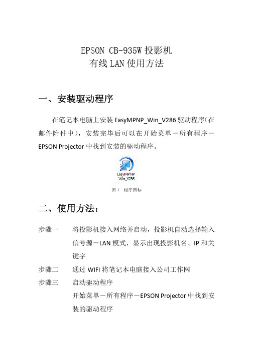
EPSON CB-935W投影机LAN连接控制说明
一
安装驱动程序
在笔记本电脑 安装 EasyMPNP_Win_V286 驱动程序 在 可以在开始菜单 所有程序
邮件附件中
安装完毕
EPSON Projector 中找到安装的驱动程序
图 1 程序图标
二
使用方法 使用方法:
将投影机 投影机接入网络并启动 投影机自动选择输入 信 键字 源 LAN 模式 显示 现投影机 IP 和关
演示完毕 关闭程序
现
一个
对话框中勾选你要放映的投影机 点
连接 会 显示
现一个小对话框 如图 4
在关键字框中输入投影机
的四位数字
投影机关键字随机
现
点
确定
图4
连接成功 在屏幕的右
时投影机显示笔记本画面 方会 现控制条 如图 5
图5
控制条
如图 6
图6
全部――可选择多个投影机 可选择多个投影机 停止――停止放影 停止放影 放映 暂停 演示模式 投影机控制 预览 设置 播放录 切断 骤五 切断 在控制条中点 切断键即可将中断演示 切断键即可将中断演示信 不支持
骤一
骤二 骤
通过 WIFI WI 将笔记本电脑接入公 启动驱动程序 开始菜单 所有程序
工作网
EPSON Projector ctor 中找到安
装的驱动程序
骤四
连接笔记本和投影机 1 启动驱动程序 动驱动程序 会 现一个对话框 如图 2:
图2
在图 2 中选择高级连接 点 对话框 如图 3
确定按键 会
爱普生 CB-695Wi教育超短焦互动投影机 产品手册
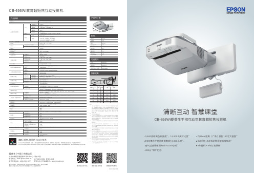
投影距离CB-695Wi 教育超短焦互动投影机SVGA 和XGA 是IBM 注册商标,NSF 是Analog Devices B.V.的商标。
本宣传页中的数据,为来源于爱普生实验室数据,与实际使用数据存在差异。
彩页中技术规格如有变更,恕不另行通知。
清晰、明亮、绚丽的3LCD 技术3LCD技术可以获取明亮、自然、柔和的图像和锐利的视频影像。
没有彩虹、色溢现象,眼睛观看也更加舒适,产品更加节能环保。
产品尺寸图清晰互动 智慧课堂图片仅供参考,外观以实物为准。
本说明若有任何细节之更改,恕不另行通知。
爱普生(中国)有限公司在法律许可的范围内对以上内容有解释权。
爱普生(中国)有限公司北京市朝阳区建国路 号华贸中心 号楼 层爱普生官方天猫旗舰店:官方网站: 服务导购热线:400-810-997781 1 4官方微信/微博:爱普生中国爱普生官方网站可选配件ELPLP91ELPAF49ELPAP10ELPPN05A ELPPN05B空气过滤网无线网卡交互式电子笔(橙色)交互式电子笔(蓝色)灯泡配件电源线USB 线遥控器电池交互式电子笔交互式电子笔电池软性笔头硬性笔头互动笔盒吊装支架手指互动组件4.5米5米AA x 22支AA x 24个2个1个1个1个1套367mm149mm400mm简便安装与运维实用功能CB-695Wi 灯泡寿命大幅提升,ECO 模式下灯泡使用寿命高达10,000小时*3,亮度更持久稳定,灯泡更换频率更低。
ECO 10,000CB-695Wi 支持6点手指、2点互动电子笔同步触控。
用户可以随心所欲的书写批注、拖动或放大缩小图片,多人同时操作时无信号延迟和卡顿现象。
8点同步触控*5CB-695Wi 自带的弧形校正功能可实现用2台投影机拼接一整个超宽屏互动画面。
互动电子笔和手指均可在超宽屏画面上自由书写、拖拽或放大缩小图片。
大型褶皱式静电吸附型防尘过滤网大幅提升投影机防尘性能,ECO 模式下使用寿命高达10,000小时*4。
爱普生投影机CB-595Wi演示

3.3% 3.4% 3.6% 4.1%
4.5%
4.7% 5.9%
10.4%
33.0%
10.9%
4.7%
7.1%
5.1% 5.5%
7.1%
5.5%5.7% 5.8% 6.9%
19.4%
16.9%
4.5% 4.7%
5.1% 6.3% 6.4% 6.7%
11.7%
9.5% 8.8%
亚太市场
18.6%
17.8%
Source: Epson estimate based on research company materials
爱普生投影机全球第一大品牌美源自市场欧洲市场20.2%
28.3%
4.2%
4.8%
4.8%
7.8%
5.0%
5.2%5.6%
7.4% 6.9%
全球市场
日本市场
23.7%
22.9%
16.2%
的 高度,显示更多的内容。 10000:1对比度,更好的色彩输出。
CB-595Wi投影机优势
灯泡亮度自动调节功能,屏幕亮度智能调节系统。 无需安装驱动,自动校准定位。 全球首款支持手指触摸,2人同时互动。 通过 MHL 连接 Andriod 智能手机和平板电脑,
轻松实现高清视频的传输。 全球唯一具有0秒关机功能,无需等待。
全球最大的生产线
• 位于中国深圳的爱普生全资生产基地
– 所在地: 中国深圳 – 面积: 86,000m2 (投影机生产面积: 8,200m2) – 成立时间: 1986
• 每一台投影机在出厂前都进行2小时检测 • 全球最大的投影机生产基地
CB-595Wi投影机介绍
CB-595Wi投影机优势
爱普生投影仪使用说明

指派要投影的图像 . . . . . . . . . . . . . . . . . . . . . . . . . . . . . . . . . . . . . . . . . . . . 29 投影指派的图像 . . . . . . . . . . . . . . . . . . . . . . . . . . . . . . . . . . . . . . . . . . . . . . 29
附录
设置选项 . . . . . . . . . . . . . . . . . . . . . . . . . . . . . . . . . . . . . . . . . . . . . . . . . . 32
常规设置选项卡 . . . . . . . . . . . . . . . . . . . . . . . . . . . . . . . . . . . . . . . . . . . . . . 32 调节参数选项卡 . . . . . . . . . . . . . . . . . . . . . . . . . . . . . . . . . . . . . . . . . . . . . . 33 音频输出选项卡 . . . . . . . . . . . . . . . . . . . . . . . . . . . . . . . . . . . . . . . . . . . . . . 33
爱普生 EB-460I 460 超短焦液晶投影机说明书
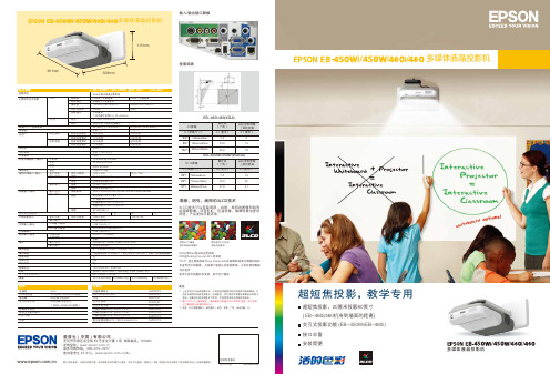
超短焦投影,20厘米投影80英寸( EB-460i/460机身到墙面的距离)交互式投影功能 (EB-450Wi/EB-460i )接口丰富安装简便超短焦投影,教学专用多媒体液晶投影机备注:选配件无线局域网卡NS Connection Key 灯泡空气过滤网交互式电子笔计算机电缆HD15 / HD15, 1.8 m 计算机电缆HD15 / HD15, 3.0 m 计算机电缆HD15 / HD15, 20.0 m复合视频电缆HD15 / 3RCA (male)3.0 mELPAP03ELPAP05ELPLP57ELPAF27ELPPN01 ELPKC02ELPKC09ELPKC10ELPKC193LCD技术可以获取明度、自然、柔和的图像和锐利的视频影像。
没有彩虹、色溢现象,眼睛观看也更加舒适,产品更加节能环保。
清晰、明亮、绚丽的3LCD技术投影距离输入/输出接口面板附件4.5m5m(仅EB-450Wi/460i标配)AA型锰干电池x2AAA型碱性电池x2(仅EB-450Wi/460i标配)电源线USB电缆线遥控器交互式电子笔密码保护标签爱普生投影机软件用户手册吊架481mm多媒体液晶投影机///EB-460i/460(XGA)/使用3LCD液晶技术制造的投影机使用单片DLP技术制造的投影机EVS100401BZ图片仅供参考,外观以实物为准。
本说明若有任何细节之更改,恕不另行通知。
爱普生(中国)有限公司在法律许可的范围内对以上内容有解释权。
爱普生(中国)有限公司北京市东城区金宝街89号金宝大厦7层 邮政编码:100005详情登陆:www .e ps 服务导购热线:400-810-9977查询爱普生4S 中心:www .e ps /4s经销商盖章处2012年4月版*1 上述时间为非承诺保修时间。
灯泡亮度将随使用时间的增加而逐渐降低。
灯 泡实际使用寿命受使用模式、环境条件、用户使用习惯等因素影响会有很大 差别。
互动投影的“宠儿”爱普生CB-1460Ui多功能智能投影机

互动投影的“宠儿”爱普生CB-1460Ui多功能智能投影机
佚名
【期刊名称】《新潮电子》
【年(卷),期】2017(000)010
【摘要】自投影机上市以来,一直是办公会议、商务演示、学术交流过程中必不
可少的设备,特别是现代技术的发展,让人们对投影机的需求不仅仅局限在高质量的大尺寸显示画面,而是需要更多与展示内容互动分享的舞台,释放演讲人的才华。
【总页数】1页(P14-14)
【正文语种】中文
【中图分类】TN946.1
【相关文献】
1.爱普生教育投影机“互动课堂中国行”与您相约 [J],
2.融入场景化教学,爱普生CB-695Wi超短焦互动投影机有点“不寻常” [J],
3.NEC VT660+多功能投影机智能灵巧 [J],
4.让教学“不寻常”——爱普生CB-695Wi超短焦互动投影机 [J],
5.爱普生教育互动投影机创新教育未来 [J],
因版权原因,仅展示原文概要,查看原文内容请购买。
爱普生家用投影机带你在家畅看《复联2》大片
爱普生家用投影机带你在家畅看《复联2》大片
佚名
【期刊名称】《消费电子》
【年(卷),期】2015(000)011
【摘要】想不排队在家躺着畅看《复仇者联盟》吗?选择爱普生CH—TW8200家用投影机,即可轻松打造自己专属的家庭影院,在家就能享受如影院效果般的震撼观影体验。
【总页数】1页(P94-94)
【正文语种】中文
【相关文献】
1.在家看3D电影 Acer H5360家用投影机 [J],
2.爱普生的亲民行动爱普生EH-TW3700C家用投影机 [J],
3.大屏看比赛精彩无与伦比:爱普生家用投影机体验活动即将拉开帷幕 [J], 本刊记者
4.打造家庭影院畅享视觉体验r爱普生带你玩转家庭影院设计大赛 [J],
5.爱普生 2015年爱普生激光4K家用投影机大戏将全国“上映” [J],
因版权原因,仅展示原文概要,查看原文内容请购买。
- 1、下载文档前请自行甄别文档内容的完整性,平台不提供额外的编辑、内容补充、找答案等附加服务。
- 2、"仅部分预览"的文档,不可在线预览部分如存在完整性等问题,可反馈申请退款(可完整预览的文档不适用该条件!)。
- 3、如文档侵犯您的权益,请联系客服反馈,我们会尽快为您处理(人工客服工作时间:9:00-18:30)。
CB-595Wi投影机优势
灯泡亮度自动调节功能,屏幕亮度智能调节系统。 无需安装驱动,自动校准定位。 全球首款支持手指触摸,2人同时互动。 通过 MHL 连接 Andriod 智能手机和平板电脑,
轻松实现高清视频的传输。 全球唯一具有0秒关机功能,无需等待。
全球最大的生产线
• 位于中国深圳的爱普生全资生产基地
– 所在地: 中国深圳 – 面积: 86,000m2 (投影机生产面积: 8,200m2) – 成立时间: 1986
• 每一台投影机在出厂前都进行2小时检测 • 全球最大的投影机生产基地
CB-595Wi投影机介绍
CB-595Wi投影机优势
3300流明高亮度,画面更加明亮。 1280x800分辨率,实现720p高清投影;确定
爱普生投影机全球第一大品牌
美国市场
欧洲市场
20.2%
28.3%
4.2%
4.8%
4.8%
7.8%
5.0%
5.2%5.6%Байду номын сангаас
7.4% 6.9%
全球市场
日本市场
23.7%
22.9%
16.2%
3.3% 3.4% 3.6% 4.1%
4.5%
4.7% 5.9%
10.4%
33.0%
10.9%
4.7%
7.1%
5.1% 5.5%
爱普生品牌介绍
爱普生投影机
爱普生公司研制成功世界上第一块LCD液 晶板,成为第一家掌握此投影机关键技术的厂家, 并制造出世界上第一台液晶投影机。
全球市场份额
FY14
Others
15.7%
Epson 全球市场占有 率第一
Source: Epson estimate based on research company materials
系统整体优势
既能实现手指交互,又可无尘书写笔书写。 更少的电子产品,更少的售后服务。
7.1%
5.5%5.7% 5.8% 6.9%
19.4%
16.9%
4.5% 4.7%
5.1% 6.3% 6.4% 6.7%
11.7%
9.5% 8.8%
亚太市场
18.6%
17.8%
5.0% 5.2%
6.7% 6.8% 7.2%
8.8%
8.2% 8.0% 7.7%
Source: (WW/A&P) Epson estimate based on research company materials, (Japan) Fuji-Kimera, (Americas) PMA, (EMEAR) Futuresource