JA安全阀说明书
安全阀作业指导书

安全阀作业指导书一、任务背景安全阀是一种用于保护压力容器或管道系统的重要设备,它可以在压力超过设定值时自动打开,释放过压的气体或液体,以确保系统的安全运行。
为了正确、安全地操作安全阀,制定一份详细的作业指导书是非常必要的。
二、任务目的本作业指导书的目的是为操作人员提供清晰的步骤和操作要点,确保他们能够正确地进行安全阀的作业,包括安装、调试、检修和维护等工作。
三、作业指导书内容1. 安全阀的基本原理- 介绍安全阀的工作原理和作用。
- 解释安全阀的结构组成和工作原理。
2. 安全阀的分类和选择- 根据工作条件和要求,介绍不同类型的安全阀。
- 提供选择安全阀的准则和方法。
3. 安全阀的安装- 详细说明安全阀的安装步骤和要求。
- 强调安全阀的正确安装位置和固定方式。
- 提供安全阀的连接方式和密封要求。
4. 安全阀的调试- 介绍安全阀的调试步骤和方法。
- 强调安全阀的调整和校验。
- 提供调试过程中可能遇到的常见问题和解决方案。
5. 安全阀的检修与维护- 详细说明安全阀的检修和维护要求。
- 提供检修和维护的周期和方法。
- 强调安全阀的清洁、润滑和密封等关键维护点。
6. 安全阀的故障排除- 列举安全阀可能出现的故障和异常情况。
- 提供故障排除的方法和步骤。
- 强调对于严重故障的处理和报告。
7. 安全阀的应急处理- 介绍安全阀在紧急情况下的应急处理方法。
- 强调对于危险情况的处理和报警。
8. 安全阀的注意事项- 提供使用安全阀时需要注意的事项和安全规范。
- 强调操作人员的安全意识和责任。
四、作业指导书的编写原则1. 简明扼要:确保指导书内容简洁明了,避免冗长和复杂的叙述。
2. 结构清晰:按照逻辑顺序组织指导书的内容,确保操作人员能够快速找到所需信息。
3. 图文并茂:通过插图、图表等方式辅助说明,提高操作人员的理解和操作效率。
4. 语言规范:使用简洁明了的语言,避免使用专业术语和复杂的句子结构。
5. 安全第一:强调操作人员的安全意识和责任,确保操作过程中的安全性。
安全阀作业指导书

安全阀作业指导书一、任务概述安全阀是一种用于保护容器或管道系统的压力安全装置,它能在压力超过预设值时自动打开,释放过多的压力,以防止设备或系统发生过压危险。
本文档旨在提供安全阀的作业指导,包括安全阀的安装、调试、操作和维护等内容。
二、安全阀的安装1. 安全阀的选型:根据容器或管道系统的工作压力和流量要求,选择适合的安全阀型号和规格。
2. 安全阀的安装位置:安全阀应安装在容器或管道系统的最高点或最靠近的出口处,以确保有效的压力释放。
3. 安全阀的安装步骤:a. 清洁安装位置,并确保没有杂物或污垢。
b. 用密封材料(如垫片)将安全阀与容器或管道系统连接。
c. 使用适当的工具紧固连接螺栓,确保连接牢固。
三、安全阀的调试1. 调试前的准备工作:a. 检查安全阀的密封性能,确保没有泄漏。
b. 检查安全阀的操作压力和流量设置,与实际要求相符。
2. 安全阀的调试步骤:a. 打开容器或管道系统的进气阀门,使其逐渐增加压力。
b. 当压力达到安全阀的操作压力时,观察安全阀是否自动打开,并检查是否有异常现象。
c. 关闭进气阀门,使压力逐渐降低,观察安全阀是否自动关闭,并检查是否有泄漏现象。
四、安全阀的操作1. 操作前的准备工作:a. 检查安全阀的工作状态,确保没有损坏或异常。
b. 检查安全阀的操作压力和流量设置,与实际要求相符。
2. 安全阀的操作步骤:a. 打开容器或管道系统的进气阀门,使其逐渐增加压力。
b. 当压力达到安全阀的操作压力时,安全阀将自动打开,释放过多的压力。
c. 关闭进气阀门,使压力逐渐降低,安全阀将自动关闭。
五、安全阀的维护1. 定期检查:每隔一段时间,对安全阀进行检查,包括外观、密封性能和操作压力等方面。
2. 清洁维护:定期清洁安全阀的内部和外部,确保没有污垢或杂物影响其正常工作。
3. 零部件更换:如果发现安全阀的零部件损坏或磨损,及时更换,确保安全阀的可靠性和稳定性。
4. 记录管理:建立安全阀的维护记录,包括检查日期、维护内容和维护人员等信息,以便追溯和管理。
安全阀作业指导书
安全阀作业指导书
标题:安全阀作业指导书
引言概述:
安全阀是一种重要的安全装置,用于保护设备和系统免受过压的危害。
本文将详细介绍安全阀的作业指导,包括安全阀的基本原理、安全阀的选型、安全阀的安装与调试、安全阀的维护与保养以及安全阀的故障排除。
一、安全阀的基本原理
1.1 安全阀的定义和作用
1.2 安全阀的工作原理
1.3 安全阀的分类及适用范围
二、安全阀的选型
2.1 根据工作介质选择安全阀材质
2.2 根据工作条件选择安全阀的工作压力和温度范围
2.3 根据流量计算选择合适的安全阀口径
三、安全阀的安装与调试
3.1 安全阀的安装位置选择
3.2 安全阀的安装要求及注意事项
3.3 安全阀的调试方法和步骤
四、安全阀的维护与保养
4.1 定期检查安全阀的工作状态
4.2 清洗和润滑安全阀
4.3 定期校验和调整安全阀的工作压力
五、安全阀的故障排除
5.1 安全阀无法正常启闭的故障排除
5.2 安全阀泄漏的故障排除
5.3 安全阀过压或欠压的故障排除
结论:
安全阀作为一种重要的安全装置,对于保护设备和系统的安全起着至关重要的作用。
通过本文的介绍,我们可以了解到安全阀的基本原理、选型、安装与调试、维护与保养以及故障排除等方面的内容,为正确、安全地操作和维护安全阀提供了指导。
在实际工作中,我们应严格按照相关规定和要求进行操作,确保安全阀的正常运行,保障设备和系统的安全性。
安全阀使用说明

安全阀使用说明
1、使用上的注意说明
因为要求该安全阀在低压力下工作,所以阀座与阀体的接触面是经过精密加工的,如果有异物附着在阀座周围,阀体动作时,异物就会被吸附到接触面上,由此形成阀体泄露的原因。
另外,请注意安全阀在搬运过程中是否受到冲击,这也是造成阀体泄露的原因。
2、安全阀的设定方法
原理:当负荷超过安全阀的设定压力时,安全阀开启,由此防止风机故障。
3、设定方法:
(1)一边观察压力表,一边旋紧闸阀,使压力超过设定压力的10%左右。
(2)松开锁定螺母,按逆时针方向旋转调节螺杆,直至从安全阀排出空气为止。
(3)若旋紧闸阀的过程中,尚未到达设定压力,安全阀已排除空气,请再一次按顺时针方向旋转调节螺杆,直至旋至不再排出空气位置,再逆时针方向旋转,恰好在排出空气为止(顺时针旋转,设定压力变高;逆时针旋转,设定压力变低)。
(4)旋紧锁定螺母和调节螺杆。
(5)松开闸阀,降低压力,使安全阀不再排气。
(6)检查安全阀是否在设定压力下工作,再次旋紧闸阀提高压力。
(7)注意:实际在排气侧有负荷时(曝气槽内达到既定水位)若闸阀全开时,设定压力比实际负荷高约10%左右。
安全阀整定装置测试说明书

安全阀整定装置校验说明书
第一步:按图连接好数显、拉力传感器、油泵、工装。
工装
调节‘调节螺帽’预紧拉力传感器
第二步:排出油缸空气
拧下右图油缸螺钉,顺时针拧紧左图油泵三角螺母,摇动油泵手柄进油,排出油缸空气后拧上油缸螺钉
第三步:归零数显仪
按‘˄’键可以在GROSS、NET、PEAK、VALLEY间切换
1、切换至‘GROSS’,按‘●’、再长按‘˅’使屏幕数字归为0
2、切换至‘PEAK’,重复以上操作使屏幕数字归为0
3、切换至‘VALLEY’,重复以上操作使屏幕数字归为0
第四步:试验
数显仪归零后,摇动油泵手柄打压至数显仪显示200kg为止。
若数显仪数字快速下降或打不到200kg,则有可能是油缸或油管密封不严等原因,检查是否漏油,拆开重装。
以上若无漏油现象,数显仪显示正常,则表示装置完好,逆时针拧松三角螺母泄压(数字会急速下降)。
并按照第三步归零数显仪。
拆卸装箱。
安全阀系列产品说明书

4
200 150 8320G182
2
200 150 8320G184
2
200 150 8320G186
2
200 150 8320G188
2
180 120 8320G136
1
180 120 8320G027
1
200 150 8320G218
4
180 120 8320G029
1
200 150 8320G219
125 65 125 50 60 20 25 75 125 60 25 12
200 125 160 100 115 40 60 160 115 60 25
200 125 160 100 100 40 55 160 100 55 30
Max. Fluid Temp. ˚F
Brass Body
Const. AC DC Catalog Number Ref.
1
8320G225
4
8320G049
1
8320G226
4
8320G231
3
8320G202 3
8320G203 3
-
-
8320G146
1
8320G051
1
8320G227
4
8320G053
1
8320G228
4
8320G055
1
8320G229
4
59
3-WAY
3/2
SERIES
8320
4
Specifications (English units)
Operating Pressure Differential (psi)
安全阀调整操作规程
安全阀调整操作规程一、引言安全阀是工业生产中常用的一种安全设备,用于保护压力容器和管道系统免受过压的危害。
为了确保安全阀的正常运行和准确调整,制定本操作规程。
二、适合范围本操作规程适合于所有使用安全阀的工业生产场所。
三、术语定义1. 安全阀:一种用于保护压力容器和管道系统的装置,能够在压力超过设定值时自动打开并释放压力。
2. 设定压力:安全阀开始打开的压力值。
3. 排放压力:安全阀彻底打开时排放的压力值。
4. 调整压力:通过调整安全阀的弹簧力或者其他机械装置,使设定压力达到预定值。
四、操作流程1. 准备工作a. 确保操作人员具备相关安全知识和操作经验。
b. 检查安全阀的型号、规格和使用条件是否符合要求。
c. 检查安全阀的密封性能和机械运动是否正常。
2. 调整前的准备a. 确定安全阀的设定压力和排放压力要求。
b. 根据设定压力和排放压力的要求,选择合适的调整工具和设备。
c. 检查安全阀的工作环境和周围设备是否安全可靠。
3. 安全阀调整a. 关闭进气阀或者切断供气管道,确保安全阀处于无压状态。
b. 使用合适的工具,拧松安全阀上的调整螺母。
c. 逐步调整螺母,使安全阀的设定压力达到预定值。
d. 打开进气阀或者恢复供气管道,观察安全阀的工作情况。
e. 如有需要,根据实际情况进行微调,使安全阀的排放压力符合要求。
4. 调整后的检验a. 检查安全阀的密封性能和机械运动是否正常。
b. 测量安全阀的设定压力和排放压力,与要求进行比对。
c. 记录安全阀的调整结果和检验数据。
五、安全注意事项1. 操作人员必须佩戴个人防护装备,包括安全帽、防护眼镜、防护手套等。
2. 在调整安全阀过程中,严禁使用过大的力量或者工具,以免损坏安全阀。
3. 在调整安全阀前,必须确保安全阀处于无压状态,以免发生意外事故。
4. 如发现安全阀存在严重的泄漏或者其他异常情况,应即将住手调整,并进行维修或者更换。
5. 操作人员必须按照操作规程进行操作,严禁擅自修改或者忽略操作步骤。
安全阀调整操作规程
安全阀调整操作规程一、概述安全阀是一种用于保护压力容器或管道系统的重要安全装置。
为了确保安全阀能正常工作,保证系统的安全性和稳定性,需要进行定期的安全阀调整操作。
本文将详细介绍安全阀调整操作规程。
二、调整前准备工作1. 确认调整对象:根据系统的压力等级和容器类型,确定需要调整的安全阀。
2. 准备工具:准备调整所需的工具,如扳手、螺丝刀、压力表等。
3. 安全措施:佩戴个人防护装备,如安全帽、安全眼镜、防护手套等。
三、安全阀调整操作步骤1. 停机准备:关闭与安全阀相关的管道系统,确保系统处于停机状态。
2. 检查安全阀:检查安全阀的外观是否完好,无损坏或渗漏现象。
3. 清洁安全阀:使用清洁剂擦拭安全阀的外表面,确保无灰尘或杂物。
4. 检查弹簧压力:使用压力表测量安全阀弹簧的压力,与设定压力进行比对。
5. 调整弹簧压力:根据实际情况,使用扳手或螺丝刀调整弹簧的压力,使其符合设定要求。
6. 检查密封性能:关闭安全阀,使用压力表测量其密封性能,确保无泄漏现象。
7. 调整开启压力:根据系统要求,使用调整装置调整安全阀的开启压力,使其符合设定要求。
8. 检查开启动作:使用压力表模拟系统压力上升,观察安全阀的开启动作是否正常。
9. 记录数据:记录安全阀调整前后的压力、弹簧压力和开启压力等数据,以备后续参考。
10. 完成调整:确认安全阀调整符合要求后,重新启动系统并进行试运行。
四、注意事项1. 操作规范:操作人员应按照标准操作程序进行调整,严禁擅自更改或调整安全阀参数。
2. 安全措施:操作人员应严格遵守安全操作规程,佩戴个人防护装备,确保人身安全。
3. 设备维护:定期对安全阀进行维护保养,清洁阀门和弹簧,确保其正常工作。
4. 数据记录:对每次安全阀调整的数据进行记录,包括调整前后的压力、弹簧压力和开启压力等,以备后续参考和分析。
五、总结安全阀调整操作是确保压力容器和管道系统安全运行的重要环节。
通过按照规程进行调整,可以保证安全阀的正常工作,并提高系统的安全性和稳定性。
安全阀作业指导书
安全阀作业指导书标题:安全阀作业指导书引言概述:安全阀是一种用于保护设备和系统的重要安全装置,其作用是在设备或系统内部压力超过设定值时,自动打开并释放压力,以防止设备或系统发生过压事故。
本文将详细介绍安全阀的作业指导,包括安全阀的基本原理、作业前的准备工作、作业过程中的注意事项、作业后的检查和维护等内容。
一、安全阀的基本原理1.1 安全阀的工作原理1.2 安全阀的分类及选择1.3 安全阀的结构和组成二、作业前的准备工作2.1 确定安全阀的工作参数2.2 检查安全阀的完好性2.3 清理和维护安全阀设备三、作业过程中的注意事项3.1 确保安全阀的工作环境3.2 正确操作安全阀3.3 防止安全阀的误操作和滞后四、作业后的检查4.2 测试安全阀的开启压力和密封性能4.3 记录和报告安全阀的作业情况五、安全阀的维护与保养5.1 定期检查和维护安全阀5.2 清洗和更换安全阀的部件5.3 做好安全阀的记录和档案管理正文内容:一、安全阀的基本原理1.1 安全阀的工作原理安全阀通过调整弹簧力和介质压力之间的平衡关系,使阀门在设定压力下打开,释放过高的压力,保护设备和系统的安全。
1.2 安全阀的分类及选择根据工作介质、工作压力和工作温度等因素,安全阀可分为弹簧式安全阀、重锤式安全阀、液力式安全阀等。
在选择安全阀时,需要根据设备和系统的工作参数确定合适的安全阀类型和规格。
1.3 安全阀的结构和组成安全阀主要由阀体、阀盖、阀簧、阀座、阀芯等部件组成。
阀体和阀盖通常采用铸铁、铸钢或不锈钢等材料制成,阀簧和阀座则采用弹簧钢或不锈钢制造。
二、作业前的准备工作在进行安全阀的作业之前,需要确定安全阀的工作压力、工作温度和工作介质等参数,并根据这些参数进行相应的调整和设置。
2.2 检查安全阀的完好性在作业前,需要对安全阀进行全面的检查,包括检查阀体和阀盖是否有裂纹、漏气等问题,检查阀簧和阀座是否完好,以确保安全阀能够正常工作。
2.3 清理和维护安全阀设备作业前需要对安全阀设备进行清洁和维护,包括清除阀体和阀盖上的杂质和污垢,检查阀簧和阀座的弹性和密封性能,并进行必要的润滑和调整。
安全阀说明书

弹簧式安全阀使用说明书安全阀一、 安全阀概述安全阀是一种自动阀门,安装在受压设备、容器或管路上,作为超压保护装置。
当设备、容器、或管路内的压力升高超过允许值时,它不借助任何外力,而是利用介质本身的压力自动开启,继而全量排放,以防止设备、容器或管路内的压力继续升高超过预定的安全值;当压力降到规定值时,安全阀自动及时关闭。
从而保护设备、容器或管路的安全运行。
安全阀的结构、应用和公称通径的确定应受到规范的约束,或者应得到法定机关的同意(如国家设置的锅炉检验所的检测)。
在不同规范之间,其约束条款以及有关定义可能不同。
在应用安全阀时,必须遵循其适用规范的要求。
由于安全阀是一种自动阀门,在结构和性能参数方面与通用阀门有许多不同之处。
为了使用户正确的选购和安全使用,特对安全阀的基本知识加以介绍。
二、 安全阀分类1.按密封件受力作用原理分为直接载荷式:如弹簧式安全阀、杠杆式安全阀;非直接作用式:如先导式安全阀(既脉冲式安全阀)。
2.按启闭件开启高度的大小可分为全启式安全阀(开启高度大于或等于流道直径的四分之一)和微启式安全阀(开启高度大于或等于流道直径的二十分之一)。
3.按密封件加载方式可分为弹簧式安全阀和杠杆式安全阀。
4.按动作特性分为比例作用式安全阀:如静重式安全阀;两段式安全阀:如弹簧式安全阀;脉冲式安全阀:5.按与管道连接的方式分为:法兰式安全阀;螺纹式安全阀;焊接式安全阀。
6.按介质工作温度分为:常温安全阀:-40℃<t ≤120℃ ;中温安全阀:120℃<t ≤450℃;高温安全阀:t >450℃;低温安全阀:-100℃<t ≤-40℃ ;7.按主体材料分为:碳素钢安全阀;合金钢安全阀;不锈钢安全阀。
三、 安全阀型号编制方法标准通用的安全阀型号通常按照JB/T308-1975《阀门型号编制方法》来编制,根据该标准,安全阀型号由下列六部分组成:对于低温(-40℃)、保温(带加热套)、带波纹管的和抗硫(抗硫化氢腐蚀)安全阀,分别在类型代号“A ”前加“D ”、 “B ”、 “W ”和“K ”来表示。
安全阀作业指导书
安全阀作业指导书【任务名称:安全阀作业指导书】一、引言安全阀是一种重要的安全设备,用于保护压力容器和管道系统免受过高压力的损害。
为了确保安全阀的正常运行和维护,制定本作业指导书,以提供详细的操作步骤和注意事项。
二、作业准备1. 工具准备:扳手、螺丝刀、润滑油等。
2. 材料准备:备用安全阀、密封垫片等。
3. 安全准备:佩戴个人防护装备,如安全帽、安全眼镜、耳塞、手套等。
三、作业步骤1. 确认作业对象:根据实际情况,确定需要进行操作的安全阀。
2. 关闭系统:在进行安全阀的作业之前,必须先关闭相关系统,确保操作的安全性。
3. 检查压力:使用压力表或其他合适的工具,检查系统内的压力,确保已降至安全操作范围内。
4. 卸压:通过逐渐打开系统的排气阀,将系统内的压力逐渐释放,直至完全卸压。
5. 拆卸安全阀:使用扳手或其他适当工具,拆卸安全阀,注意阀门的位置和连接方式,避免损坏或泄漏。
6. 清洁和检查:将拆卸下来的安全阀进行清洁,并仔细检查阀门和密封垫片的状况,如有磨损或损坏应及时更换。
7. 安装新阀门:将新的安全阀安装至原位,确保阀门与连接口完全贴合,并使用扳手适当拧紧。
8. 测试:重新启动系统,逐渐增加压力,观察安全阀是否正常工作,确保其能够在设定的压力范围内自动打开并释放压力。
9. 调整:如发现安全阀的打开压力不符合要求,可使用调整螺钉进行微调,直至满足要求为止。
10. 记录和报告:将作业过程中的关键数据和操作记录进行整理,并向相关人员报告作业结果。
四、注意事项1. 严格按照操作规程进行作业,不得随意更改或省略步骤。
2. 在操作过程中,必须佩戴个人防护装备,确保人身安全。
3. 作业前必须对系统进行彻底的检查,确保完全卸压和安全。
4. 在拆卸和安装安全阀时,应注意阀门的位置和连接方式,避免错误操作。
5. 在重新启动系统前,必须确保新安装的安全阀能够正常工作。
6. 如发现安全阀的打开压力不符合要求,应及时进行调整,确保其正常工作。
安全阀说明书
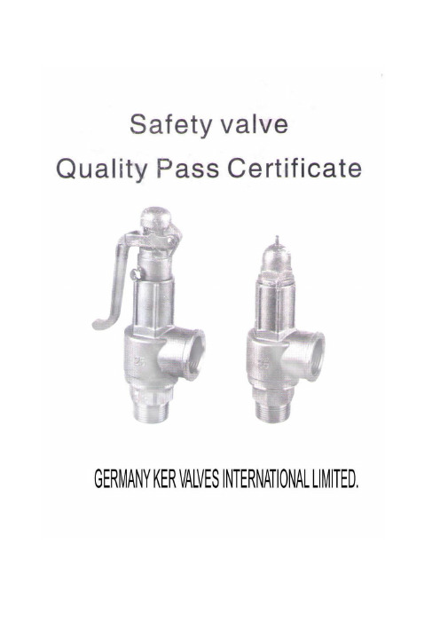
Knowledge of safety relief valves introducedSafety relief valve is a safe and protected with a valve, opening and closing parts of its external force is normally closed by the state, when the device or media pressure inside the tubes increases, exceeds the value of open automaticallyEmissions through the media outside the system to prevent the medium pressure piping or equipment exceeds the value, safety relief valves are automatic valves, mainly used for boilers, pressure vessels and piping,Control pressure does not exceed the value of personal safety and equipment operation play an important protective role.Safety relief valve by valve opening height can be divided into inching safety relief valve and the entire Kai safety relief valves, safety relief valve inching height of the opening stroke, ≤ 0.05d0 (throat diameter minimum emissions );Kai-type safety relief valves full opening height is ≤ 0.25d0 (minimum emissions throat diameter).Safety relief valve according to the structure form of points to be divided into vertical hammer, lever, spring-type and (pulse), body structure according to points, can be divided into closed and not closed two,Safety relief valve that is closed to exclude the media is not compromised, all along the exit discharge to designated location, usually used in the toxic and corrosive media, for the safety of air and steam pressure relief valve,To use more safety relief valve is not closed, the safety relief valve products for the selection of the actual sealing pressure should be determined. For the spring-loaded safety relief valve, in a nominal pressure (PN) within theWorking pressure level has several springs, except as noted when ordering safety relief valve type, name, medium and temperature, there should specify the pressure valve seal, or by the maximum sealing pressure supply.Safety relief valve installation and maintenance should note the following, a variety of safety relief valve should be installed vertically, the safety relief valve outlet should be no resistance, to avoid the phenomenon of pressure, safety relief valve should be specifically tested before installation and check its official seal, the use of the safety relief valve should be checked regularly.First, knowledge of safety relief valves overviewSafety relief valve is boilers, pressure vessels and other pressure equipment subject to important safety accessories.Reliability and performance of its action is directly related to equipment and personal security, and with energy conservation and environmental protection are closely related.Second, the definition of safety relief valves safety relief valve called the broad sense, including relief valve, from the rules point of view, directly installed in the steam boiler or pressure vessel onThe necessary conditions must be approved valve technology supervision department, called the safety relief valve on the narrowly defined, other general discharge valve.Safety relief valves and relief valves in the structure and performance is very similar, both are more than open automatically when the discharge pressure of the internal medium, to ensure plant safety. By the existence of such a nature similar to the dry nature, it is in use,Often confuse the two, In addition, some production facilities are also provided in the rules which can be used. Therefore, the difference between the two is often overlooked. So also there were many problems.If you want to make a more precise definition, may be in accordance with the "ASME Boiler and Pressure Vessel Code"First articulated in the definition to understand,1, the safety relief valve (SafetyValve) a static pressure from the valve before the media-driven automatic pressure relief device, characterized by a sudden opening of all open action. For gas or steam applications.2, the relief valve (ReliefValve), also known as a kind of relief valve before the media by the static pressure-driven automatic pressure relief device. It opened with the pressure exceeds the growth of power in proportion to open. Mainly used for fluid situations.3, the safety relief valve (SafetReliefValve), also known as pressure safety relief valve of a media driven by the automatic pressure relief device.Use different according to both valid for the safety relief valve is also valid for the relief valve. Japan, for example, to the safety relief valves and relief valves to less clearly defined,General large-scale energy storage such as a boiler pressure vessel safety device called the safety relief valve, installed in the pipe or other established facilities in the bleed valve. But under MITI's "thermal technology" of the device an important part of the safety and security,Specify the use of safety relief valves, such as the boiler, superheater, reheater, and so on. In the valve of the lower side with the boilers and turbines phase of the occasion,Relief valve to be installed or safety relief valve. This view, the safety relief valve is more reliable than the relief valve requirements. In addition, from the Japanese Ministry of Labor's high-pressure gas management rules,Ministry of Transport and Shipping Association rules at all levels, the identification of safety and emissions regulations, we take the guarantee of emissions called safety relief valves,Not guarantee emissions valve called the relief valve. Kai in the country regardless of type or Weiqi collectively referred to as safety relief valve.Third, the safety relief valve selection1, the safety relief valve of the classification, the current mass production of the safety relief valve spring and the rod are two major categories. There are also impulse-type safety relief valves, safety relief valve, safety valve switch,Safety release valve, the static weight safety relief valve. Spring-loaded safety relief valve spring force and rely mainly on the work of the spring-type safety relief valve in the closed and not closed, generally flammable,Explosive or toxic media should use closed, steam or inert gas used is not closed, the spring-loaded safety relief valve with a wrench in there and without wrenches. Wrench key is to examine the role of the flexibility of the disc, and sometimes can also be used manually with emergency relief. Lever-type safety relief valve lever hammer rely mainly on the force and work,However, the safety relief valve lever is often bulky and limit the range of choice. At high temperature safety relief valve with a radiator. The main parameters of the safety relief valve is the displacement,The displacement depends on the caliber of the valve seat and valve opening height, from the opening height, then divided into Weiqi and all Kai two.Weiqi is the valve opening height for the seat throat diameter of 1 / 40 ~ l/20. All Kai is the valve opening height of seat throat diameter of 1 / 4.2, the selection of the safety relief valve, operating pressure determined by the nominal pressure safety relief valve, operating temperature determined by the use of safety relief valves temperature rangeSecurity from the calculated value of constant pressure relief valve spring or lever decide the scope of constant pressure, then under the decision to use media materials and the safety relief valve structure type,According to the safety relief valve Discharge calculated safety relief valve throat diameter. The following is the safety relief valve used in the general rule.(L) hot water boilers generally is not closed with a wrench inching safety relief valve.(2) steam boiler or steam pipe generally is not closed with a wrench for type safety relief valve.(3), water and other liquids can not be closed for general use compressed medium inching safety relief valve or safety relief valve.(4) high-pressure water supply general use of closed-type safety relief valve, such as high pressure feedwater heater, heat exchanger.(5) gas and other compressible medium for general use of closed-type safety reliefvalve, such as the gas tank, gas pipelines.(6) E-class steam boilers generally static weight safety relief valve.(7) large diameter, large displacement and high pressure systems typically use pulse type safety relief valve, such as temperature and pressure reduction equipment, boiler, and so on.(8) transportation of liquefied gas tanker train car tanker, tanks and other general use built-in safety relief valve.(9) tank top general, hydraulic safety relief valve, to be used in conjunction with the breathing valve.(10) underground water or gas pipes for general use safety relief valve.(11) Liquefied petroleum gas station can pump liquid return pipe back to normal with the safety valve.(12) or negative pressure during operation may have negative pressure systems generally use vacuum safety relief valve.(13) back pressure and toxic volatile flammable container or piping systems are generally used bellows safety relief valve.(14) medium low freezing point of the system is generally used in thermal insulation jacket safety relief valve.Mainly consists of the following categories,(1) (API526 Wire Joints safety relief valve) (Wire Joints safety relief valve) based American Standard system.Chemical equipment with safety relief valve connection sizes are generally in accordance with this standard, as shown.All of the standard nominal diameter of DN15 ~ DN200 (l / 2 "~ 8"), nominal pressure of 0.1 ~ 2500bar, throat diameter from D-T (9.5 ~ 146mm).Comparison of the standard scientific norms, pressure, material, temperature, throat diameter and so overall consideration. Throat diameter determined in accordance with specifications, the same throat diameter can have several specifications,On the contrary may be the same size pipe diameter can choose several. Such as 4 "to 6" diameter pipe with L, M, N, P are four to choose from.(2) the greatest impact in the international company based in Germany KER safety relief valve (KDA21W) series.Commonly known as safety relief valves,As shown, the safety relief valve from the main valve and pilot valves, pilot valve operating the main valve is opened and closed. The valve displacement large; from the impact of back pressure;Can be very close to not leak under pressure to open operation; advantages, such as blowdown. Generally applicable to natural gas pipelines.No current international standards and safety relief valve connection size standards. And this type of valve development, no widely.According to my factory experience and available information, the international standards of most manufacturers in accordance with the API design and manufacturing data, such as Germany. Corey Valve Co., Ltd.Anderson Greenwood (AndersonGreenwood & Co.) And so on.4, the throat diameter of the throat diameter calculated according to the calculation of the general, "Boiler and Pressure Vessel Safety Technical Code" in accordance with APIRP520 refinery pressure relief system design and installation of the first part of the recommended implementation of the method of design "Listed in the formula. The results of these two formulas the same or not materially different.(9) tank top general, hydraulic safety relief valve, to be used in conjunction with the breathing valve.(10) underground water or gas pipelines general safety relief valve with the pilot.(11) Liquefied petroleum gas station can pump liquid return pipe back to normal with the safety valve.(12) or negative pressure during operation may have negative pressure systems generally use vacuum safety relief valve.(13) back pressure and toxic volatile flammable container or piping systems are generally used bellows safety relief valve.(14) medium low freezing point of the system is generally used in thermal insulation jacket safety relief valve.Mainly consists of the following categories,(1) API526 "steel flanged safety relief valve" (FlangedSteelSafetyReliefValve)-based American Standard system.Chemical equipment with safety relief valve connection sizes are generally in accordance with this standard, as shown.All of the standard nominal diameter of DN15 ~ DN200 (l / 2 "~ 8"), nominal pressure of 0.1 ~ 2500bar, throat diameter from D-T (9.5 ~ 146mm).Comparison of the standard scientific norms, pressure, material, temperature, throat diameter and so overall consideration. Throat diameter determined in accordance with specifications, the same throat diameter can have several specifications,On the contrary may be the same size pipe diameter can choose several. Such as 4 "to 6" diameter pipe with L, M, N, P are four to choose from.(2) the greatest impact in the international company based in Germany Corey safety relief valve (PilotOperatedPressureReliefValves) series.Commonly known as pilot-type safety relief valve,As shown, the pilot safety relief valve from the main valve and pilot valves, pilot valve operating the main valve is opened and closed. The valve displacement large; from the impact of back pressure;Can be very close to not leak under pressure to open operation; advantages, such as blowdown. Generally applicable to natural gas pipelines.No pilot present international safety standards and pressure relief valve connection size standards. And this type of valve development, no widely.According to my factory experience and available information, the international standards of most manufacturers in accordance with the API design and manufacturing data, such as Germany. KER Valve Co., Ltd.Anderson Greenwood (AndersonGreenwood & Co.) And so on.4, the throat diameter of the throat diameter calculated according to the calculation of the general, "Boiler and Pressure Vessel Safety Technical Code" in accordance with APIRP520 refinery pressure relief system design and installation of the first part of the recommended implementation of the method of design "Listed in the formula. The results of these two formulas the same or not materially different.。
JA-3安全阀说明书.doc08.8.2
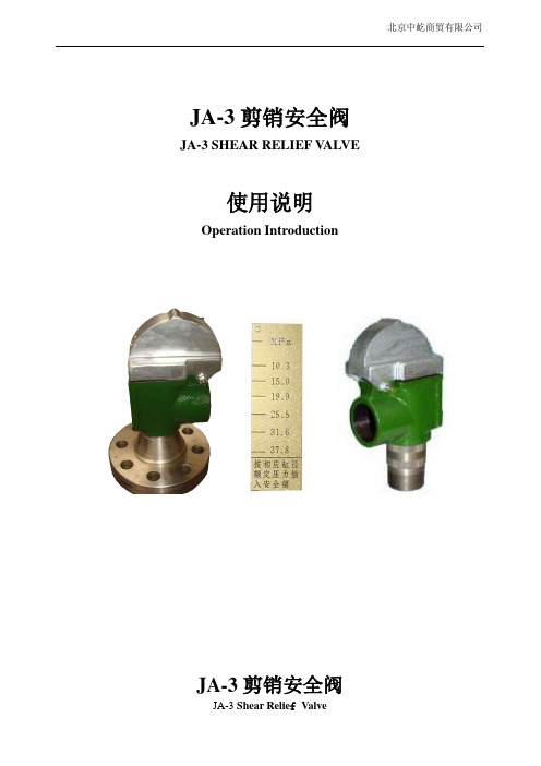
JA-3剪销安全阀JA-3 SHEAR RELIEF V ALVE使用说明Operation IntroductionJA-3剪销安全阀JA-3 Shear Relie f ValveJA-3剪销安全阀法兰接头JA-3 Shear Relief Valve Flange Union JointJA-3剪销安全阀结构如上图所示。
当压力高出额定知时,(3)活塞升起,顶起剪切板(10)以剪短剪切销(11)从而快速排空压力。
JA-3剪销安全阀靠改变剪切销的位置进而达到排出压力的效果,操作简单。
所标示的压力被可在剪切板上。
当要调节压力时,只要把剪切销插到相对应的孔里即可。
注意,一个剪切销只允许插入一个剪切板中。
缸套尺寸同剪销安全阀压力变化相关。
禁止使用铁丝,焊条或替他物质代替。
那将安全阀压力受到影响而引发事故。
The structure of JA-3 shear relief valve is showed above. When the pressure is more than the rated data, the piston⑶raises, jacks up the shear board⑽to break off the shear pin⑾so as to empty the sap flow promptly.JA-3 shear relief valve change the leaked pressure with the poison movement of shear pin. It operates simply.Pressure level mark is carved on the shear board. You only need insert the shear pin into the relative hole when you want to adjust the operation pressure. Note, only one shear pin is allowed to insert in shear board. Liner size is changed relatively adjust the relief valve pressure. The use of steel wire, welding rod or other materials is forbidden. That will effect pressure of relief valve and cause the accident.。
阿尔法拉夫安全阀说明书

12 bar. The valve can be operated either pneumatically or manually. It is delivered with PED certificate and complies with PED 2014/68/EU and EN 4126-1, fluid group II (non-hazardous fluids). It is available for pressure regulation of both liquids and gases. Please note that manual pressure regulation of gases has a reduced pressure range.Working principleThe Alfa Laval Safety Valve prevents inadmissible overpressures of fluids in tanks, containers and plant sections. It is factory-configured with the specified set pressure that is greater than the operating pressure. If the operating pressure rises above the set pressure, the valve opens against the spring force to relieve pressure.The valve should be installed in a vertical position for optimal performance. If mounted in a horizontal position, the set pressure will be somewhat lower than specified due to the lack of weight from the piston. The highest effect is obtained using DN80 and DN100.TECHNICAL DATAMax. sterilisation temperature, dry steam:140 °C (Max 30 min)PHYSICAL DATAOther steel parts: 1.4301 (304)Seals:EPDMExternal finish:Ra 1.5-2.5 µm Internal finish:Ra 0.8 µmConnections:Inlet: Liner/nut DIN 11851Outlet: Male DIN 11851Option:Inductive sensor for feedback is available for standard and pneumatic lifting - see instruction manual for detail.Dimensions (mm)Figure 1. Standard DN25Figure 2. Standard DN40-DN100Figure 3. Standard DN25with inductive sensor for feedbackFigure 4. Standard DN40-DN100 with inductive sensor for feedbackDN403238Rd65x1/6Rd65x1/6688225566 9.1DN503850Rd78x1/6Rd78x1/6709330166 1.3DN655066Rd95x1/6Rd95x1/68510540266 15.0DN806681Rd110x1/4Rd110x1/4100115407.566 22.0DN10081100Rd130x1/4Rd130x1/41301304186628.2DN403238Rd65x1/6Rd65x1/66882255663389.1DN503850Rd78x1/6Rd78x1/6709330166384 1.3DN655066Rd95x1/6Rd95x1/6851054026648415.0DN806681Rd110x1/4Rd110x1/4100115407.56648922.0DN10081100Rd130x1/4Rd130x1/41301304186650128.2Figure 5. Manual lifting DN25Figure 6. Manual lifting DN40-DN100Figure 7. Pneumatic lifting DN25 with inductive sensor for feedbackFigure 8. Pneumatic lifting DN40-DN100 with inductive sensor for feedbackDN403238Rd65x1/6Rd65x1/66882255152-232 10.3DN503850Rd78x1/6Rd78x1/67093301154-234 15.5DN655066Rd95x1/6Rd95x1/685105402153-233 16.2DN806681Rd110x1/4Rd110x1/4100115407.5152.5-232.5 23.2DN10081100Rd130x1/4Rd130x1/4130130418152-23229.6DN403238Rd65x1/6Rd65x1/66882255663389.1DN503850Rd78x1/6Rd78x1/6709330166384 1.3DN655066Rd95x1/6Rd95x1/6851054026648415DN806681Rd110x1/4Rd110x1/4100115407.56648922DN10081100Rd130x1/4Rd130x1/41301304186650128.2Opening and closing characteristics for incompressible fluids (Liquid)Max. operating pressure (P over )0.90.80.20 (1 atm)Set pressure (P set )Closing pressure (P close )P (bar)Max. operating pressure (P over ):10 % of set pressure or 0.1 bar, whichever is the greater.Closing pressure (P close ):Maximum 20% or 0.6 bar below set pressure, whichever is the greater.(Example: Set pressure = 0.8 bar)Opening and closing characteristics for compressible fluids (Gas)Max. operating pressure (P over )0.90.80.50 (1 atm)Set pressure (P set )Closing pressure (P close )P (bar)Max. operating pressure (P over ):10 % of set pressure or 0.1 bar, whichever is the greater.Closing pressure (P close ):Maximum 15% or 0.3 bar below set pressure, whichever is the greater.(Example: Set pressure = 0.8 bar)Blow-off performance chart2001-0060051015202530354045Set pressure (bar)Pressure range [bar]A = 0.5 - 1.5B = 1.6 - 2.5C = 2.6 - 4.5D = 4.6 - 7.0E = 7.1 - 12.0123456789101112ABEDCFlow rate [m³/h]Figure 9. DN25 set pressure: 0.2 - 12.0 bar for liquids (water 20 °C)2001-00802505007501,0001,2501,5001,7502,000Flow rate [m³/h]Set pressure (bar)Pressure range [bar]A = 0.2 - 1.5B = 1.6 - 2.5C = 2.6 - 4.5D = 4.6 - 7E = 7.1 - 120123456789101112ACEBDFigure 10. DN 25 set pressure: 0.2 - 12 bar for gases (air 20 °C)Note!DN25 for gas application up to 1,5 bar fulfills the DIN4126-1 requirements. For higher pressures the valve is approved by TÜV .ABDC2001-0062Pressure range [bar]A = 0.2 - 1.0B = 1.1 - 3.0 C = 3.1 - 7.0D = 7.1 - 12.0510152025303540455055012345678910111260Set pressure (bar)Flow rate [m³/h]Figure 11. DN 40 set pressure: 0.2 - 12.0 bar for liquids (water 20 °C)025********,0001,2501,5001,7502,0002,2502,5002,7500123456789101112ABDC2001-0063Set pressure (bar)Pressure range [bar]A = 0.2 - 1.0B = 1.1 - 3.0C = 3.1 - 7.0D = 7.1 - 12.0Flow rate [m³/h]Figure 12. DN 40 set pressure: 0.2 - 12.0 bar for gases (air 20 °C)1234567891011120102030405060708090100110ABEDC2001-0064Set pressure (bar)Pressure range [bar]A = 0.3 - 0.9B = 1.0 - 1.7C = 1.8 - 2.9D = 3.0 - 6.0E = 6.1 - 12.0Flow rate [m³/h]Figure 13. DN 50 set pressure: 0.3 - 12.0 bar for liquids (water 20 °C)012345 6 78910111205001,0001,5002,0002,5003,0003,5004,0004,500A BEDC2001-0065Set pressure (bar)Pressure range [bar]A = 0.3 - 0.9B = 1.0 - 1.7C = 1.8 - 2.9D = 3.0 - 6.0E = 6.1 - 12.0Figure 14. DN50 set pressure: 0.3 - 12.0 bar for gases (air 20 °C)010********60708090100110120130140150160170180012345 6789A BDC2001-0066Set pressure (bar)Flow rate [m³/h]Pressure range [bar]A = 0.4 - 1.5B = 1.5 - 3.0C = 3.1 - 7.0D = 7.1 - 9.0Figure 15. DN65 set pressure: 0.4 - 9.0 bar for liquids (water 20 °C)5001,0001,5002,0002,5003,0003,5004,0004,5005,0005,5006,0006,5007,0007,500012345 6789ABDC2001-0067Set pressure (bar)Flow rate [m³/h]Pressure range [bar]A = 0.4 - 1.5B = 1.5 - 3.0C = 3.1 - 7.0D = 7.1 - 9.0Figure 16. DN65 set pressure: 0.4 - 9.0 bar for gases (air 20 °C)Pressure range [bar]A = 0.3 - 0.9B = 1.0 - 1.9C = 2.0 - 3.3D = 3.4 - 4.3E = 4.4 - 8.0020406080100120140160180200220240260280012345 6 787.56.55.54.53.52.51.50.5A B DC 2001-0068ESet pressure (bar)Figure 17. DN80 set pressure: 0.3 - 8.0 bar for liquids (water 20 °C)5001,0001,5002,0002,5003,0003,5004,0004,5005,0005,5006,0006,5007,0007,5008,0008,5009,000012345 6 787.56.55.54.53.52.51.50.5ABDC2001-0069ESet pressure (bar)Pressure range [bar]A = 0.3 - 0.9B = 1.0 - 1.9C = 2.0 - 3.3D = 3.4 - 4.3E = 4.4 - 8.0Flow rate [m³/h]Figure 18. DN80 set pressure: 0.3 - 8.0 bar for gases (air 20 °C)02040608010012014016018020022001232.51.50.5ABC2001-0070Set pressure (bar)Pressure range [bar]A = 0.3 - 1.1B = 1.2 - 1.8C = 1.9 - 3.2Flow rate [m³/h]Figure 19. DN100 set pressure: 0.3 - 3.2 bar for liquids (water 20 °C)5001,0001,5002,0002,5003,0003,5004,0004,5005,0005,5006,00001232.51.50.5ABC2001-0071Set pressure (bar)Pressure range [bar]A = 0.3 - 1.1B = 1.2 - 1.8C = 1.9 - 3.2Figure 20. DN100 set pressure: 0.3 - 3.2 bar for gases (air 20 °C)This document and its contents are subject to copyrights and other intellectual property rights owned by Alfa Laval Corporate AB. No part of this document may be copied, re-produced or transmitted in any form or by any means, or for any purpose, without Alfa Laval Corporate AB’s prior express written permission. Information and services provided in this document are made as a benefit and service to the user, and no representations or warranties are made about the accuracy or suitability of this information and these services for any purpose. All rights are reserved.200003950-2-EN-GB© Alfa Laval Corporate ABHow to contact Alfa LavalUp-to-date Alfa Laval contact details for all countries are always available on our website at 。
安全阀作业指导书
安全阀作业指导书一、引言安全阀是一种用于保护设备或系统的重要安全装置,其作用是在系统压力超过设定值时,自动打开并释放压力,以防止设备或系统发生过压危险。
本作业指导书旨在提供对安全阀的正确操作和维护的指导,以确保设备和系统的安全运行。
二、安全阀的基本原理安全阀的工作原理是通过压力作用在阀芯上的力,使阀芯与阀座分离,从而打开阀门,释放过压。
当压力降低到设定值以下时,阀芯与阀座重新接触,阀门关闭,停止释放压力。
三、安全阀的安装与调试1. 安装位置:安全阀应安装在系统的出口处,以便及时释放过压。
安装位置应远离热源和震动源,并确保有足够的空间进行维护和操作。
2. 连接方式:安全阀应采用正确的连接方式,如螺纹连接或法兰连接。
连接处应密封良好,以防泄漏。
3. 调试:安装完成后,应进行调试,确保安全阀的工作压力与系统的设计压力一致。
调试时应注意阀门的打开和关闭是否灵活,是否有异常噪音或漏气现象。
四、安全阀的操作1. 操作前准备:操作人员应熟悉安全阀的工作原理和操作要求,并穿戴好相关的个人防护装备。
2. 操作步骤:a. 检查:先检查安全阀是否处于关闭状态,确认周围环境是否安全。
b. 打开:轻轻旋开安全阀的手轮,使阀门逐渐打开,释放过压。
c. 观察:观察安全阀是否正常工作,是否有异常现象。
d. 关闭:当压力降低到安全范围内时,轻轻旋紧手轮,使阀门关闭。
3. 操作注意事项:a. 操作人员应保持冷静,严禁在操作过程中戏弄或滥用安全阀。
b. 操作过程中应注意观察安全阀的工作状态,如有异常应及时报告上级或维修人员。
c. 操作结束后,应将操作记录填写完整并存档。
五、安全阀的维护与检修1. 定期检查:定期对安全阀进行检查,包括外观检查、密封性检查和动作性能检查。
如发现异常,应及时进行维修或更换。
2. 清洁保养:定期清洁安全阀的内部和外部,确保阀门的灵活性和密封性。
3. 防腐防锈:对暴露在潮湿环境中的安全阀,应进行防腐防锈处理,以延长使用寿命。
JAGGER VALVE 单动气阀电磁阀说明书
screw type
~
=
manual operator
374A061/062/063
-
C140037
374A016/017/018 C140038 C140038
374A046/047/048 C140038 C140038
374A027/028
C140042 C140042
374A057/058
C140042 C140042
3
3/2
Series
374
1
2
BP
MP
RP
LP
Not available
Not available
Not available
10,5W-11,2W
Low power
Reduced power
Medium power
Basic power
POWER LEVELS - cold electrical holding values (watt)
374A022
C140039 C140039
374A052
C140039 C140039
C140048 C140048 C140072 C140048 C140072 C140048 C140072
SelectBforNPTANSI1.20.3orselectEforISO(228/1and7/1) ● Availablefeature - Notavailable
Example: 230V / 50Hz
STEP5 Finalcatalogue/orderingnumber.
Example:
EME374A016MS 230 V / 50 Hz
安全阀说明书

安全阀说明书第 1 页共 15 页目录一、用途二、主要零件的作用及结构特点三、安装1.安全阀安装2.排汽管的安装3、输水管的安装四、现场调试1.调试前准备2.新供货的阀门校验性试验3.检修后的阀门调整方法4.上、下调整环、调整套位置表示方法五、解体与装配1.局部解体2.局部解体后装配3.总解体4.总解体后装配六、研磨1.研磨工具的准备2.研磨胎具的制作3.研磨七、安全阀主要零件维护及更换标准八、订货须知一、用途安全阀用于蒸汽温度≤580℃,整定压力≤14MPa的锅炉,压力容器。
以防止蒸汽压力超过规定值,确保设备安全运行,整套阀门是按照日本冈野阀门株式会社全量型安全阀技术制造。
二、主要零件的作用及结构特点安全阀结构如图所示。
安全阀阀座设计成拉伐尔喷嘴形状,阀座内径大于等于1.15倍喉部直径,安全阀达到全开位置时,阀座口处流通面积大于1.05倍喉部面积。
根据拉伐尔喷嘴介质流动原理阀座出口介质流速达到音速,使安全阀排放系数大于0.75。
阀座突出在阀体内,避免阀体热应力对阀座密封面的影响,密封件采用了热阀瓣,并与阀瓣套筒用阀瓣螺母固定在一起,避免阀瓣套筒和阀瓣的热应力对阀瓣密封面的影响,提高了密封性。
热阀瓣用韧性好、强度高、抗冲刷、耐高温的材料制作,热阀瓣如图 -1所示,其优点是当密封面有少量蒸汽漏泄时,漏出的蒸汽降压同时降温。
热阀瓣舌头形状下部温度低于上部温度,舌头部位产生弯曲,后部就翘起,舌头部位紧接触于阀座上,增加了密封比压,提高密封能力。
当介质压力升高,介质作用力与弹簧力相平衡时,漏量无法避免。
漏量增加到一定程度时下调整环上部与热阀瓣下部形成的压力区域内的内压力将随着漏量增加而迅速增加,改变蒸汽对阀瓣的作用力,而使介质有足够的力,克服弹簧力,使阀门启跳,调整下调整环的位置高低,改变压力区域内压力,能得到满意的启跳压力,调整上调整环位置的高低,改变流体对阀瓣的反作用力,能影响阀门启跳高度和影响回座压力,当调整环得不到满意的回座压力时,可调整调整套位置,改变阀瓣背压,就可得到满意的回座压力。
安全阀操作规程

安全阀操作规程一、安全阀开启压力的调整①安全阀出厂前,应逐台调整其开启压力到用户要求的整定值。
若用户提出弹簧工作压力级,则一般应按压力级的下限值调整出厂。
②使用者在将安全阀安装到被保护设备上之前或者在安装之前,必须在安装现场重新进行调整,以确保安全阀的整定压力值符合要求。
③在铭牌注明的弹簧工作压力级范围内,通过旋转调整螺杆改变弹簧压缩量,即可对开启压力进行调节。
④在旋转调整螺杆之前,应使阀进口压力降低到开启压力的90%以下,以防止旋转调整螺杆时阀瓣被带动旋转,以致损伤密封面。
⑤为保证开启压力值准确,应使调整时的介质条件,如介质种类、温度等尽可能接近实际运行条件。
介质种类改变,特别是当介质聚积态不同时(例如从液相变为气相),开启压力常有所变化。
工作温度升高时,开启压力一般有所降低。
故在常温下调整而用于高温时,常温下的整定压力值应略高于要求的开启压力值。
高到什么程度与阀门结构和材质选用都有关系,应以制造厂的说明为根据。
⑥常规安全阀用于固定附加背压的场合,当在检验后调整开启压力时(此时背压为大气压),其整定值应为要求的开启压力值减去附加背压值。
二、安全阀排放压力和回座压力的调整①调整阀门排放压力和回座压力,必须进行阀门达到全开启高度的动作试验,因此,只有在大容量的试验装置上或者在安全阀安装到被保护设备上之后才可能进行。
其调整方法依阀门结构不同而不同。
②对于带反冲盘和阀座调节圈的结构,是利用阀座调节圈来进行调节。
拧下调节圈固定螺钉,从露出的螺孔伸人一根细铁棍之类的工具,即可拨动调节圈上的轮齿,使调节圈左右转动。
当使调节圈向左作逆时针方向旋转时,其位置升高,排放压力和回座压力都将有所降低。
反之,当使调节圈向右作顺时针方向旋转时,其位置降低,排放压力和回座压力都将有所升高。
每一次调整时,调节:圈转动的幅度不宜过大(一般转动数齿即可)。
每次调整后都应将固定螺钉拧上,使其端部位于调节圈两齿之间的凹槽内,既能防止调节圈转动,又不对调节圈产生径向压力。
- 1、下载文档前请自行甄别文档内容的完整性,平台不提供额外的编辑、内容补充、找答案等附加服务。
- 2、"仅部分预览"的文档,不可在线预览部分如存在完整性等问题,可反馈申请退款(可完整预览的文档不适用该条件!)。
- 3、如文档侵犯您的权益,请联系客服反馈,我们会尽快为您处理(人工客服工作时间:9:00-18:30)。
J A安全阀说明书
The Standardization Office was revised on the afternoon of December 13, 2020
JA-3剪销安全阀JA-3 SHEAR RELIEF VALVE
使用说明
Operation Introduction
JA-3剪销安全阀
JA-3 Shear Relie f Valve
JA-3剪销安全阀法兰接头
JA-3 Shear Relief Valve Flange Union Joint
Item No. (1) (2) (3)
JA-3剪销安全阀结构如上图所示。
当压力高出额定知时,(3)活塞升起,顶起剪切板(10)以剪短剪切销(11)从而快速排空压力。
JA-3剪销安全阀靠改变剪切销的位置进而达到排出压力的效果,操作简单。
所标示的压力被可在剪切板上。
当要调节压力时,只要把剪切销插到相对应的孔里即可。
注意,一个剪切销只允许插入一个剪切板中。
缸套尺寸同剪销安全阀压力变化相关。
禁止使用铁丝,焊条或替他物质代替。
那将安全阀压力受到影响而引发事故。
The structure of JA-3 shear relief valve is showed above. When the pressure is more than the rated data, the piston⑶ raises, jacks up the shear board⑽ to break off the shear pin⑾ so as to empty the sap flow promptly.
JA-3 shear relief valve change the leaked pressure with the poison movement of shear pin. It operates simply.
Pressure level mark is carved on the shear board. You only need insert the shear pin into the relative hole when you want to adjust the operation pressure. Note, only one shear pin is allowed to insert in shear board. Liner size is changed relatively adjust the relief valve pressure. The use of steel wire, welding rod or other materials is forbidden. That will effect pressure of relief valve and cause the accident.。
