某工业以太网交换机手册
S3000工业以太网交换机 用户手册

S3000工业以太网络交换机用户手册上海宽域工业网络设备有限公司Shanghai Kuanyu Industrial Network Equipment Co.,Ltd.目录第1章概述 (1)第2章满足标准 (2)第3章选型指南 (3)第4章技术指标参数 (4)4.1 系统参数 (4)4.2 通信接口参数 (4)4.3 管理端口参数 (4)4.4 电源参数 (5)4.5 机械参数 (5)4.6 环境条件参数 (5)4.7 无故障率参数 (5)第5章功能介绍 (6)第6章结构尺寸 (8)6.1 安装尺寸 (8)6.2 通信接口 (9)6.3 电源及告警端子 (10)6.4 指示灯 (12)第1章概述APEX S3000系列交换机是上海宽域工业网络设备有限公司自主研发的工业以太网通信产品,适用于工业现场各种工作环境,能满足高低温、过电压、漏电及高压冲击等各种要求,并对严酷的电磁环境中的数据口防雷、快速脉冲群、浪涌、静电等方面作了可靠性设计,支持全双工、半双工工作模式,具有工作速率自检测和自适应能力,支持MDI/MDI-X自动极性反转。
APEX S3000系列以太网交换机适用于变电站综合自动化系统、电厂监控系统、工业控制系统等。
可提供千兆以太网接口,提供更高的数据传输速率,满足日益发展的设备通信需求。
APEX S3000系列交换机采用高性能的交换芯片和优秀的工业设计,可在所有端口满负载运行下保持线速转发,产品的设计制造充分考虑了工业应用环境中的各种恶劣条件和干扰因素,可保证数据在严苛环境下可靠传输。
APEX S3000工业以太网交换机是专业为电力系统设计的高可靠性、高抗干扰、宽温度及宽电压工作范围的电力通信产品,符合以下技术标准:IEC61000-4-2(静电):接触放电±8kV、空气放电±15kV;IEC61000-4-3(电磁场):10V/mIEC61000-4-4(快速瞬变):电源线±4kV、数据线±2kV;IEC61000-4-5(浪涌):电源线:线/地±4kV、线/线±2kV;数据线:线/地±1kV;IEC61000-4-6(射频传导):3V(10kHz~150kHz)、10V(150kHz~80MHz);IEC61000-4-8(工频磁场):100A/m连续、1000A/m 1s到3s;IEC61850-3(变电站网络通信);IEEE1613(变电站环境标准);APEX S3000选型表:说明:(1)S3016-F8T8、S3024-F16T8支持双电源,默认单电源输入,若有特殊需求可在订货时注明;(2)100Base-FX光口标配为ST多模1310nm光模块,若需其他类型光模块可在订货时注明。
PMC-2108工业级以太网交换机用户说明书_V1.0

5.1
装置上电后工作不正常........................................................................................................ 10
5.2
交换机出现部分端口不通的问题该如何处理? ................................................................... 10
6.2
软件升级 ..............................................................................................................................11
6.3
质保范围 ..............................................................................................................................11
4.1
外观....................................................................................................................................... 5
4.2
指示灯说明............................................................................................................................ 5
SIMATIC NET 工业以太网交换机 SCALANCE XC-100 操作说明说明书

3.3
LED 指示灯 ..................................................................................................................... 19
3.4
SET 按钮 ........................................................................................................................ 20
5.3
电源 ................................................................................................................................ 33
5.4
信号触点 ......................................................................................................................... 35
危险 表示如果不采取相应的小心措施,将会导致死亡或者严重的人身伤害。
警告 表示如果不采取相应的小心措施,可能导致死亡或者严重的人身伤害。
小心 表示如果不采取相应的小心措施,可能导致轻微的人身伤害。
注意 表示如果不采取相应的小心措施,可能导致财产损失。
当出现多个危险等级的情况下,每次总是使用最高等级的警告提示。如果在某个警告提示中带有警告可能导致人身伤 害的警告三角,则可能在该警告提示中另外还附带有可能导致财产损失的警告。
KORENIX JETNET 工业以太网交换机 产品应用手册
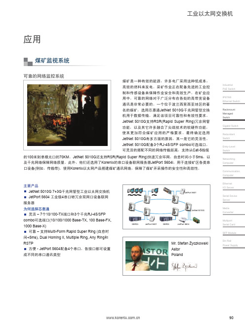
Industrial PoE Switch IP67/68 Ethernet Switch Rackmount Managed SwitchGigabit Switch Redundant Switch Entry-Level Switch Networking Computer Communication Computer Ethernet I/O ServerSerial Device Server Media Converter Multiport Serial Card SFP Module Din RailPower Supply工业以太网交换机煤矿是一种有效的能源,许多电厂采用这种低成本,高效的燃料来发电。
采矿作业正在配备先进的工业控制和传感设备来保障作业安全和高效生产。
在矿业应用中,可靠的网络对于广泛分布在各处的高带宽设备通讯是非常必要的。
一个位于波兰西里西亚地区的著名的煤矿,选用芯惠通JetNet 5010G 千兆网管型交换机用于数据传输,满足该项目可靠性和有效性要求。
JetNet 5010G 支持RSR(Rapid Super Ring)冗余网管功能,以及其它许多融合了尖端技术的软硬件功能,使其更加符合煤矿应用的严格要求。
最终确定选用JetNet 5010G 有多方面的原因,其一是它的灵活性。
JetNet 5010G 配备3个RJ-45/SFP combo 可选端口,可灵活的搭配不同的网络传输距离,支持从Cat-5线缆的100米到单模光口的70KM 。
JetNet 5010G 还支持RSR(Rapid Super Ring)快速冗余环网,自愈时间小于5ms ,以及千兆网络保障网络质量。
此外,他们还选用了Korenix 的串口设备联网服务器JetPort 5604i ,用于连接矿区各类串口设备(例如,传输带)。
使用Korenix 以太网产品搭建煤矿通讯网络,保障了煤矿开采操作的安全性和高效性。
PSW 618A工业以太网交换机说明书V1.0

-40℃~+70℃ 5%~95%(产品内部既不应凝露,也不应结冰)
2.3 环境条件 2.3.1 温度
2
工作:-40℃~+70℃。 贮存:-40℃~+85℃,相对湿度不大于 80%,不施加激励量,交换机不出现不可逆的变化,温度恢复 后,交换机能正常工作。 2.3.2 相对湿度 5%~95%(产品内部既不应凝露,也不应结冰)。 2.3.3 大气压力 66kPa~110kPa
2.1.1 直流电源 a)额定电压:220V、110V; b)允许偏差:-20%~+10%; c)纹波系数:不大于 5%
2.1.2 交流电源 PSW618A 工业以太网交换机支持交流 220V/50Hz 的电源工作。
2.1.3 功率消耗 额定负载下,交换机消耗功率不大于 20W。
2.1.4 接点容量 告警信号空接点容量: a) 允许长期通过电流:DC220V 1A; b) 切断电流:3A;
国电南自技术部监制
目录
安全声明 版本声明
1 概述.................................................................................. 1 1.1 适用范围 ......................................................................... 1 1.2 功能配置及型号 ................................................................... 1 1.3 性能特点 ......................................................................... 1
DPtech LSW3003系列工业以太网交换机典型配置手册v1.3

LSW3003系列工业以太网交换机典型配置手册手册版本:v1.3软件版本:LSW3003-M231S003D006P015DPtech LSW3003系列工业以太网交换机典型配置手册v1.3.docx声明Copyright © 2008-2016杭州迪普科技有限公司版权所有,保留一切权利。
非经本公司书面许可,任何单位和个人不得擅自摘抄、复制本书内容的部分或全部,并不得以任何形式传播。
为杭州迪普科技有限公司的商标。
对于本手册中出现的其他所有商标或注册商标,由各自的所有人拥有。
由于产品版本升级或其他原因,本手册内容有可能变更。
杭州迪普科技有限公司保留在没有任何通知或者提示的情况下对本手册的内容进行修改的权利。
本手册仅作为使用指导,杭州迪普科技有限公司尽全力在本手册中提供准确的信息,但是杭州迪普科技有限公司并不确保手册内容完全没有错误,本手册中的所有陈述、信息和建议也不构成任何明示或暗示的担保杭州迪普科技有限公司地址:杭州市滨江区通和路68号中财大厦6层邮编:310051网址:邮箱:support@7x24小时技术服务热线:400-6100-59约定图形界面格式约定各类标志约定表示操作中必须注意的信息,如果忽视这类信息,可能导致数据丢失、功能失效、设备损坏或不可预知的结果。
表示对操作内容的描述进行强调和补充。
目录1产品概述 (1)1.1 Web管理 (1)1.1.1登陆Web管理界面 (1)1.1.2 Web界面布局介绍 (2)2管理员 (3)2.1管理员简介 (3)2.2管理员配置 (3)3远程管理 (4)3.1 Telnet配置 (4)3.2 SSH配置 (6)4软件版本升级 (8)4.1简介 (8)4.2软件版本升级 (8)5基本二三层转发 (10)5.1 VLAN简介 (10)5.2端口类型 (11)5.3二层转发简介 (11)5.3.1配置需求 (11)5.3.2网络拓扑 (12)5.3.3配置流程 (12)5.3.4配置步骤 (12)5.4配置步骤 (13)5.4.1配置需求 (13)5.4.2网络拓扑 (14)5.4.3配置流程 (14)5.4.4配置步骤 (14)6端口聚合 (17)6.1简介 (17)6.2端口聚合配置案例 (17)6.2.1配置需求 (17)6.2.2网络拓扑 (18)6.2.3配置流程 (18)6.2.4配置步骤 (18)7端口镜像 (20)7.1简介 (20)7.2端口镜像的基本概念 (20)7.3端口镜像配置案例 (21)7.3.1配置需求 (21)7.3.2网络拓扑 (21)7.3.3配置流程 (21)7.3.4配置步骤 (21)8静态路由 (23)8.1简介 (23)8.2静态路由配置案例 (23)8.2.1配置需求 (23)8.2.2网络拓扑 (23)8.2.3配置流程 (23)8.2.4配置步骤 (24)9生成树 (26)9.1生成树简介 (26)9.2 STP配置案例 (27)9.2.1配置需求 (27)9.2.2网络拓扑 (27)9.2.3配置流程 (27)9.2.4配置步骤 (28)9.3 RSTP配置案例 (31)9.3.1配置需求 (31)9.3.2网络拓扑 (32)9.3.3配置流程 (32)9.3.4配置步骤 (32)1产品概述1.1Web管理1.1.1登陆Web管理界面Web管理界面的登陆方法:(1) 确认主机同交换机系统管理口通讯正常。
系列工业以太网交换机标准手册

一、ZV ANCOM CARART44-N系列工业以太网互换机简介●从应用环境方面:1.通过国家电力4级电磁兼容测试2.宽电源范畴,交直流110V~220V3.宽环境温度,-40℃~70℃4.无电扇设计,消除故障点●从性能方面1.背板带宽高达15.3Gpps,可以满足所有端口旳线速互换2.MAC地址体现8K,可以存储8000多种网络地址,支持大型网络3.高达32M旳数据缓存4.高达6.6Mpps旳转发能力5.模块化设计,可按需配备6.支持两个千兆模块,可用于骨干网建设●从功能方面1.支持广播风暴克制(计算每秒每端口进入旳广播包数量,超过设定值旳将丢弃)2.支持3层互换和VLAN管理3.支持RSTP技术(迅速生成树合同,用于避免环路)4.支持QOS技术,保证网络服务质量5.支持RIP、OSPF、VRRP等路由合同6.可通过CONSOLE、SNMP、WEB、TELNET等方式管理二、ZV ANCOM CARART44-N系列工业以太网互换机配备措施本措施主采用CONSOLE串口方式配备前准备工作:1、将互换机包装箱内串口线连接至计算机串口后开机。
2、在计算机上打开超级终端,顺序(以XP为例):开始>所有程序>附件>通讯>超级终端3、在超级终端端口属性中,将连接所用串口属性设立为:恢复默认值4、等待互换机完毕启动,浮既有WELCOME TO SPROS 时即可进行配备。
有关功能配备命令⑴、启用互换机RSTP功能。
RSTP为迅速生成树合同,启用此功能可避免由于误插网线形成环路所引起旳广播风暴所导致旳网络瘫痪。
同步此功能可将环路中旳某路做为热备链路,当其他链路发生中断时,此热备链路可迅速恢复为正常工作状态,从而保证网络通信。
注:RSTP功能与STP功能混用效果不好。
应当与支持相似合同旳互换机配合使作。
措施:1、在串口连接后,敲回车登录互换机。
2、浮现提示login:3、输用顾客名admin ,回车4、浮现提示password:5、回车。
Cisco工业以太网5000系列交换机数据手册说明书
Cisco Industrial Ethernet 5000 Series SwitchesData sheet Cisco publicContentsProduct overview 3 Features and benefits 3 Cisco ONE Software 5 Product specifications 6 Ordering information 16 Warranty information 17 Cisco environmental sustainability 17 Cisco and Partner Services 17 Cisco Capital 17 For more information 18Developed specifically to withstand the harshest industrial environments, these switches offer the most flexible and scalable industrial Ethernet platform that grows with your network.Product overviewThe Cisco® Industrial Ethernet (IE) 5000 Series Switches with four 10 Gigabit or four 1 Gigabit Ethernet uplinks and 24 Gigabit Ethernet downlinks is a rack mount, ruggedized switch that provides Layer 2 and Layer 3 line rate aggregation and copper Power over Ethernet (PoE) connectivity in the harshest of industrial environments. The IE 5000 Series uses superior high-bandwidth hardware switching and proven Cisco IOS® Software. TheIE 5000 is highly secure and scalable for access and aggregation layer deployments. It also provides Cisco stackable technologies for advanced network reliability. The switch is built to withstand extreme environments while adhering to overall IT network design, compliance, and performance requirements. The IE5000 has built-in SW image verification to ensure authenticity of the Cisco Software.The IE 5000 Series can be used to easily and securely extend the enterprise network to harsh environments with a software-defined access extension for the Internet of Things (IoT) enabling connectivity in outdoor areas, warehouses, distribution centers, roadways, etc., using powerful enterprise-grade intent-based network management platform such as Cisco DNA Center.The IE 5000 Series is ideal for industrial Ethernet applications where hardened products are required. This includes utility industries, manufacturing, energy and process control, Intelligent Transportation Systems (ITS), oil and gas field sites, city surveillance programs, and mining. With improved overall performance, greater bandwidth with available 10 Gigabit Ethernet interfaces, a richer feature set, and enhanced hardware, the Cisco IE 5000 Series Switches complement the current Industrial Ethernet portfolio of products. This portfolio includes Cisco industrial Ethernet switches, such as the Cisco IE 2000, IE 3200, IE 3300, IE 3400, IE 4000 and IE 4010 Series Switches, as well as utility - focused products, such as the Cisco IE 2000U Industrial Ethernet switches and Cisco 2500 Series Connected Grid Switches.Through a user-friendly web device manager, the IE 5000 provides easy out-of-the-box configuration and simplified operational manageability to deliver advanced security, data, video, and voice services over industrial networks.Features and benefitsTable 1 lists the features and benefits of Cisco IE 5000 Series Switches.Table 1.Features and benefits of Cisco IE 5000 Series SwitchesThe Cisco Industrial Ethernet 5000 Series Switches offer:●Bandwidth and capacity to grow with your networking needs: High-performance non-blocking switchcapacity with up to 24 Gigabit Ethernet downlink ports and four 10 Gigabit or four 1 Gigabit Ethernet uplink ports per switch●SFP+ heater to allow standard SFP+ optics to operate to -40C (10GE SKU only)●Cisco IOS Software features for smooth IT integration and policy consistency●Robust resiliency enabled by features, such as dual-ring design through four 10 Gigabit Ethernet uplinkports, Resilient Ethernet Protocol (REP), Parallel Redundancy Protocol (PRP), PROFINET– MediaRedundancy Protocol (MRP) ring, High Availability Seamless Redundancy (HSR) ring, EtherChannel, Flex Links, redundant power input, and dying gasp●Oven-controlled crystal oscillator (OCXO) to provide superior frequency stability needed for precisesynchronization applications●Simplified software upgrade path with universal images●Integrated support for features such as GPS receiver and IRIG●Cisco DNA Center management and support for software-defined access extension for IoTCisco ONE SoftwareCisco ONE Software offers a simplified consumption model, centered on common customer scenarios in the industrial automation and extended enterprise environments. Cisco ONE Software and services provide customers with four primary benefits:●Software suites that address typical customer use scenarios at an attractive price●Investment protection for their software purchase through software services-enabled license portability●Access to ongoing innovation and new technology with Cisco Software Support Service (SWSS)●Flexible licensing models to smoothly distribute customers' software spending over timeFigure 1 shows switch models, Table 2 shows all the available IE 5000 models, Table 3 lists the power supplies and Table 4 shows the available power budget for PoE/PoE+ for Cisco IE 5000 Series Switches Series Switches.Figure 1.IE 5000 switchTable 2.Cisco Industrial Ethernet 5000 Series models1 Uplink ports can run at 1 Gigabit Ethernet or 10 Gigabit Ethernet mode depending on the SFP or SFP+ inserted.2 Can be upgraded to IP Services license with the PID in Table 15.Table 3.Power supplies for Cisco IE 5000 Series SwitchesTable 4.Available power budget for PoE/PoE+ with different power supply wattageProduct specificationsTable 5 lists specifications, Table 6 lists information about Physical specifications, Table 7 lists information about switch performance and scalability, Tables 8 and 9 list important software license features, Tables 10-11 list the Cisco DNA Essentials and Advantage features. Table 12 lists compliance specifications, and Table 13 lists information about management and standards and Table 14 lists the supported SFPs on Cisco IE 5000 Series SwitchesTable 5.Product specificationsTable 6.Physical specificationsTable 7.Switch performance and scalabilityTable 8.Cisco IE 5000 Key LAN Base Software features1 Full flexible Netflow is included is included on all IE-5000 Switches and requires either one of the following licenses per switch:●Cisco ONE™ Foundation Perpetual license●Cisco DNA Essentials license●Cisco IP Services licenseTable 9.Cisco IE 5000 IP services license: Key software featuresTable 10.Cisco IE 5000 DNA Essentials featuresTable 11.Cisco IE 5000 DNA Advantage featuresTable pliance specificationsTable 13.Management and standardsIEEE standards ●IEEE 802.1D MAC Bridges, STP●IEEE 802.1p Layer2 COS prioritization●IEEE 802.1q VLAN●IEEE 802.1s Multiple Spanning-Trees●IEEE 802.1w Rapid Spanning-Tree●IEEE 802.1x Port Access Authentication●IEEE 802.1AB LLDP●IEEE 802.3ad Link Aggregation (LACP)●IEEE 802.3af Power over Ethernet provides up to15.4W DC power to each end device●IEEE 802.3at Power over Ethernet provides up to25.5W DC power to each end device ●IEEE 802.3af Power over Ethernet●IEEE 802.3at Power over Ethernet Plus●IEEE 802.3ah 100BASE-X SMF/MMF only ●IEEE 802.3x full duplex on 10BASE-T●IEEE 802.3 10BASE-T specification●IEEE 802.3u 100BASE-TX specification ●IEEE 802.3ab 1000BASE-T specification ●IEEE 802.3z 1000BASE-X specification ●IEEE 1588v2 PTP Precision Time ProtocolRFC compliance ●RFC 768: UDP●RFC 783: TFTP●RFC 791: IPv4 protocol●RFC 792: ICMP●RFC 793: TCP●RFC 826: ARP●RFC 854: Telnet●RFC 951: BOOTP●RFC 959: FTP●RFC 1157: SNMPv1●RFC 1901,1902-1907 SNMPv2●RFC 2273-2275: SNMPv3●RFC 2571: SNMP Management●RFC 1166: IP Addresses●RFC 1256: ICMP Router Discovery ●RFC 1305: NTP●RFC 1492: TACACS+●RFC 1493: Bridge MIB Objects●RFC 1534: DHCP and BOOTP interoperation●RFC 1542: Bootstrap Protocol●RFC 1643: Ethernet Interface MIB●RFC 1757: RMON●RFC 2068: HTTP●RFC 2131, 2132: DHCP●RFC 2236: IGMP v2●RFC 3376: IGMP v3●RFC 2474: DiffServ Precedence●RFC 3046: DHCP Relay Agent Information Option ●RFC 3580: 802.1x RADIUS●RFC 4250-4252 SSH ProtocolSNMP MIB objects ●BRIDGE-MIB●CALISTA-DPA-MIB●CISCO-ACCESS-ENVMON-MIB●CISCO-ADMISSION-POLICY-MIB●CISCO-AUTH-FRAMEWORK-MIB●CISCO-BRIDGE-EXT-MIB●CISCO-BULK-FILE-MIB●CISCO-CABLE-DIAG-MIB●CISCO-CALLHOME-MIB●CISCO-CAR-MIB●CISCO-CDP-MIB●CISCO-CIRCUIT-INTERFACE-MIB●CISCO-CLUSTER-MIB●CISCO-CONFIG-COPY-MIB●CISCO-CONFIG-MAN-MIB●CISCO-DATA-COLLECTION-MIB●IF-MIB●CISCO-DHCP-SNOOPING-MIB ●CISCO-SNMP-TARGET-EXT-MIB●CISCO-STACK-MIB●CISCO-STACKMAKER-MIB●CISCO-STP-EXTENSIONS-MIB●CISCO-SYSLOG-MIB●CISCO-TCP-MIB●CISCO-UDLDP-MIB●CISCO-VLAN-IFTABLE-RELATIONSHIP-MIB ●CISCO-VLAN-MEMBERSHIP-MIB●CISCO-VTP-MIB●ENTITY-MIB●ETHERLIKE-MIB●HC-RMON-MIB●IEEE8021-PAE-MIB●IEEE8023-LAG-MIB●IF-MIB●IP-FORWARD-MIB●IP-MIB●CISCO-EMBEDDED-EVENT-MGR-MIB●IP-MIB●CISCO-ENTITY-ALARM-MIB●CISCO-ENTITY-SENSOR-MIB●CISCO-ENTITY-VENDORTYPE-OID-MIB●LLDP-MIB●CISCO-ENVMON-MIB●CISCO-ERR-DISABLE-MIB●CISCO-FLASH-MIB●CISCO-FTP-CLIENT-MIB●CISCO-IF-EXTENSION-MIB●CISCO-IGMP-FILTER-MIB●CISCO-IMAGE-MIB●CISCO-IP-STAT-MIB●CISCO-LAG-MIB●CISCO-LICENSE-MGMT-MIB●CISCO-MAC-AUTH-BYPASS-MIB●OLD-CISCO-TCP-MIB●CISCO-MAC-NOTIFICATION-MIB●OLD-CISCO-TS-MIB●CISCO-MEMORY-POOL-MIB●CISCO-PAE-MIB●CISCO-PAGP-MIB●CISCO-PING-MIB●CISCO-PORT-QOS-MIB●CISCO-PORT-SECURITY-MIB●CISCO-PORT-STORM-CONTROL-MIB●SNMP-NOTIFICATION-MIB●CISCO-PRIVATE-VLAN-MIB●CISCO-PROCESS-MIB●CISCO-PRODUCTS-MIB●CISCO-RESILIENT-ETHERNET-PROTOCOL-MIB ●SNMP-VIEW-BASED-ACM-MIB●CISCO-RTTMON-ICMP-MIB●CISCO-RTTMON-IP-EXT-MIB●CISCO-RTTMON-MIB●CISCO-RTTMON-RTP-MIB ●LLDP-EXT-MED-MIB●LLDP-MIB●NETRANGER●NOTIFICATION-LOG-MIB●OLD-CISCO-CHASSIS-MIB●OLD-CISCO-CPU-MIB●OLD-CISCO-FLASH-MIB●OLD-CISCO-INTERFACES-MIB ●OLD-CISCO-IP-MIB●OLD-CISCO-MEMORY-MIB●OLD-CISCO-SYS-MIB●OLD-CISCO-SYSTEM-MIB●OLD-CISCO-TCP-MIB●OLD-CISCO-TS-MIB●RMON-MIB●RMON2-MIB●SMON-MIB●SNMP-COMMUNITY-MIB●SNMP-FRAMEWORK-MIB●SNMP-MPD-MIB●SNMP-NOTIFICATION-MIB●SNMP-PROXY-MIB●SNMP-TARGET-MIB●SNMP-USM-MIB●SNMP-VIEW-BASED-ACM-MIB ●SNMPv2-MIB●TCP-MIB●UDP-MIBTable 14.SFP supportNote:For DOM support and for first software release supporting SFP, refer tohttps:///en/US/products/hw/modules/ps5455/products_device_support_tables_list.html.Not all SFPs are supported in PROFINET GSD for SIMATIC STEP7/TIA Portal. Please visithttps:///c/en/us/td/docs/switches/lan/industrial/software/configuration/guide/b_sfp_TIA.html.Ordering informationTable 15 lists the ordering information for Cisco IE 5000 system. Table 15.Ordering informationWarranty information for the IE 5000 switch is available at/warrantyfinder.aspx.Cisco environmental sustainabilityInformation about Cisco’s environmental sustainability policies and initiatives for our products, solutions, operations, and extended operations or supply chain is provided in the “Environment Sustainability” section of Cisco’s Corporate Social Responsibility (CSR) Report.Reference links to information about key environmental sustainability topics (m entioned in the “Environment Sustainability” section of the CSR Report) are provided in the following table:Cisco makes the packaging data available for informational purposes only. It may not reflect the most current legal developments, and Cisco does not represent, warrant, or guarantee that it is complete, accurate, or up to date. This information is subject to change without notice.Cisco and Partner ServicesAt Cisco, we’re committed to minimizing our customers’ TCO, and we offer a wide range of services programs to accelerate customer success. Our innovative programs are delivered through a unique combination of people, processes, tools, and partners, resulting in high levels of customer satisfaction. Cisco Services helps you protect your network investment, optimize network operations, and prepare your network for new applications to extend network intelligence and the power of your business. Some of the key benefits our customers can get from Cisco Services follow:●Mitigating risks by enabling proactive or expedited problem resolution●Lowering TCO by taking advantage of Cisco expertise and knowledge●Minimizing network downtime●Supplementing your existing support staff so they can focus on additional productive activitiesFor more information about Cisco Services, refer to Cisco Technical Support Services or Cisco Advanced Services at https:///web/services/Cisco CapitalFlexible payment solutions to help you achieve your objectives.Cisco Capital makes it easier to get the right technology to achieve your objectives, enable business transformation and help you stay competitive. We can help you reduce the total cost of ownership, conserve capital, and accelerate growth. In more than 100 countries, our flexible payment solutions can help you acquire hardware, software, services and complementary third-party equipment in easy, predictable payments. Learn more.For more information about the Cisco IE 5000 Series, visit https:///go/ie5000 or contact your local account representative.Printed in USA C78-734967-12 07/20。
SICOM3000A-LITE 工业以太网交换机 硬件安装手册说明书

SICOM3000A-LITE工业以太网交换机硬件安装手册出版日期:2019年03月版本:V1.0编号:112020173SICOM3000A-LITE工业以太网交换机硬件安装手册免责声明:北京东土科技股份有限公司竭力使本手册中的信息尽可能准确、最新。
然而本公司不能保证本手册完全没有任何技术错误或笔误,并保留在未通知用户的情况下对其修改的权利。
保留所有权限:本手册著作权属北京东土科技股份有限公司所有。
未经著作权人书面许可,任何单位或个人不得以任何方式摘录、翻版、复制、翻译或者用于商业目的分发等行为。
侵权必究。
Copyright © 2019Kyland Technology Co., Ltd.安全使用须知本产品在设计使用范围内具有良好可靠的性能,但需要避免人为对设备造成的损害或破坏。
使用设备前,请仔细阅读该手册,以保障用户人身和设备的安全。
阅读后请妥善保管本手册,以备将来参考。
对于违反安全使用须知造成的人身伤害或设备损坏,我司不承担任何责任。
●请勿将设备放置、安装在接近水源或潮湿的地方,保持设备周边的相对湿度在5%~95%范围内且无凝结。
●请勿将设备放置、安装在高磁、强震或高温的地方,保持设备的工作、存储温度在规定范围内。
●保持设备放置稳妥,防止坠落;保持设备安装紧固,防止滑脱。
●保持设备及周边环境清洁,必要时可用干软棉布擦拭。
●请勿在设备或线缆上放置杂物,保持设备散热通畅,线缆顺畅无打结。
●操作设备时需佩戴防静电手套或采取其他安全防护。
●接线时避免金属线裸露,防止金属线高温氧化或联电。
●需按照本国、本地电器法规安装设备。
●上电前需确认设备支持的电源规格,防止电压过高损坏设备。
●保持电源插头及其它设备连接件连接牢固,防止接触不良影响使用。
●请勿用湿手插拔电源,断电前请勿用湿手触摸设备及设备配套零件。
●操作带电设备前,请取下首饰(戒指、手镯、手表、项链等)或其他金属物品,防止触电或烫伤。
某工业以太网交换机手册
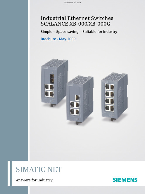
1EinführungSIMATIC NETAnswers for industry.Industrial Ethernet Switches SCALANCE XB-000/XB-000GSimple – Space-saving – Suitable for industry Brochure · May 2009Industrial Ethernet Switches SCALANCE XB-000/XB-000GBenefits•Implementing a machine network even under constant cost pressure•Space-saving installation thanks to small, compact design •Quick commissioning without configuration•Easy on-site diagnostics via LEDsApplication areaThe unmanaged Industrial Ethernet switches of theSCALANCE XB-000/XB-000G line allow cost-effective solu-tions for setting up small star or line topologies with switching functionality in machinery or plant components. The enclo-sure is designed for space-saving installation in a control cabinet on a standard rail. Wall mounting is also possible. Product versionsAll versions can be diagnosed directly on the device using LEDs (power, link status data traffic)Versions for the construction of electrical Industrial Ethernet star and line topologies with:Fast Ethernet (100 Mbit/s):•SCALANCE XB005 and SCALANCE XB008;5 or 8 x 10/100 Mbit/s electrical RJ45 portsGigabit Ethernet (1000 Mbit/s):•SCALANCE XB005G and SCALANCE XB008G;5 or 8 x 10/100/1000 Mbit/s electrical RJ45 ports Versions for the construction of electrical and optical Industrial Ethernet star and line topologies with:Fast Ethernet (100 Mbit/s):•SCALANCE XB004-1 and SCALANCE XB004-1LD;4 x 10/100 Mbit/s electrical RJ45 ports and1 x 100 Mbit/s optical SC port (multimode/singlemode,glass)Gigabit Ethernet (1000 Mbit/s):•SCALANCE XB004-1G and SCALANCE XB004-1LDG;4 x 10/100/1000 Mbit/s electrical RJ45 ports and1 x 1000 Mbit/s optical SC port (multimode/singlemode,glass) DesignThe SCALANCE XB-000/XB-000G Industrial Ethernet switches are optimized for mounting on a standard rail.They have:• A 3-pin terminal block for connecting the power supply (1x24 V DC) and functional ground.•An LED to display status information (Power)•LEDs for indicating the status information (link status and data exchange) per portThe following port types are available:•10/100 BaseTX electrical RJ45 ports or10/100/1000 BaseTX electrical RJ45 ports;automatic data transmission rate detection(10/100/1000 Mbit/s), with Autosensing and Autocrossing function for connecting IE TP cables up to 100 m.•100 BaseFX, optical SC port for direct connection to the Indus-trial Ethernet FO cables. Multimode fiber-optic cable up to 3 km •100 BaseFX, optical SC port for direct connection to the Industrial Ethernet FO cables. Single mode fiber-optic cable up to 26 km •1000 BaseSX optical SC port for direct connection to the Industrial Ethernet FO cables.Multimode fiber-optic cable up to 750 m•1000 BaseLX optical SC port for direct connection to the Indus-trial Ethernet FO cables. Singlemode fiber-optic cable up to 10 km Function•Construction of electrical Industrial Ethernet line or star topologies•Use of uncrossed connecting cables is possible due to the integrated Autocrossing function of the ports•Simple network configuration and network expansion;no restriction on network expansion when cascading the switches.SCALANCE XB004-1Industrial Ethernet Switches2Industrial Ethernet Switches3Network topology and network configurationThe SCALANCE XB-000/XB-000G switches are typically in-stalled with the stations to be connected in a control cabinet or control box. When configuring the network, it is necessary to observe the following boundary conditions:•Length of the TP cable between two SCALANCE XB-000/ XB-000G switches -max. 100 m-max. 10 m via patch cable with TP Cord-max. 100 m via Industrial Ethernet FC Outlet RJ45, IE FC Standard Cable and TP Cord •Length of fiber-optic cables:-max. 3 km with Industrial Ethernet FO cables multimode-max. 26 km with Industrial Ethernet FO cables singlemode DiagnosticsThe following information is indicated on the device by means of LEDs:•Power •Port status •Data trafficElectrical star topology with SCALANCE XB005G for the connection of ter-minal devices and connection to higher-level network structures with Gigabit EthernetElectrical star topology with SCALANCE XB005 for the connection of ter-minal devices with Fast EthernetMixed star topology with SCALANCE XB004-1 or SCALANCE XB004-1GThe information provided in this brochure contains descriptions or characteristics of performance which in case of actual use do not always apply as described or which may change as a result of further development of the products. An obligation to provide the respective characteristics shall only exist if expressly agreed in the terms of contract. Availability and technical specifications are subject to change without notice.All product designations may be trademarks or product names of Siemens AG or supplier companies whose use by third parties for their own purposes could violate the rights of the owners.Siemens AG Industry SectorSensors and Communication Postfach 48 4890026 NÜRNBERG GERMANYSubject to change without prior notice Order No.: 6ZB5530-1AS02-0BA13P.8101.46.16 / Dispo 26000BR 0509 2.0 ROT 4 En Printed in Germany © Siemens AG 2009/simatic-netOrdering dataTechnical specificationsIndustrial Ethernet Switches SCALANCE XB-000/XB-000Gunmanaged Industrial Ethernet Switches for 10/100/1000 Mbit/s,IP20 degree of protection, incl. operating instructions, Industrial Ethernet Network manual on CD-ROM SCALANCE XB0055 x 10/100 Mbit/s RJ45 electrical RJ45 ports6GK5 005-0BA00-1AB2SCALANCE XB005G5 x 10/100/1000 Mbit/s electrical RJ45 ports6GK5 005-0GA00-1AB2SCALANCE XB0088 x 10/100 Mbit/s RJ45 electrical RJ45 ports6GK5 008-0BA00-1AB2SCALANCE XB008G8 x 10/100/1000 Mbit/s electrical RJ45 ports6GK5 008-0GA00-1AB2SCALANCE XB004-14 x 10/100 Mbit/s electrical RJ45 ports and 1x 100 Mbit/s optical SC port (multimode, glass), up to 3 km 6GK5 004-1BD00-1AB2SCALANCE XB004-1G4 x 10/100/1000 Mbit/s RJ45 electrical RJ45 ports and 1x 1000 Mbit/s optical SC port (multimode, glass), up to 750 m 6GK5 004-1GL00-1AB2SCALANCE XB004-1LD4 x 10/100 Mbit/s electrical RJ45 ports and 1 x 100 Mbit/s optical SC port (singlemode, glass), up to 26 km 6GK5 004-1BF00-1AB2SCALANCE XB004-1LDG4 x 10/100/1000 Mbit/s electrical RJ45 ports and 1 x 1000 Mbit/s optical SC port (singlemode, glass), up to 10 km6GK5 004-1GM00-1AB2IE TP Cord RJ45/RJ45TP cable 4 x 2 with 2 RJ45 connectors■0,5 m ■ 1 m ■ 2 m ■ 6 m ■10 m6XV1 870-3QE506XV1 870-3QH106XV1 870-3QH206XV1 870-3QH606XV1 870-3QN10FO Standard Cable GP 50/125Fiber-optic cable, pre-assembled with 4 SC connectors (not for SCALANCE XB004-1LD/XB004-1LDG)■80 m ■100 m ■150 m ■200 m ■300 m6XV1 873-6AN806XV1 873-6AT106XV1 873-6AT156XV1 873-6AT206XV1 873-6AT30InterfacesConnection of terminal equipment or network components via twisted pair4, 5 or 8 x 10/100/1000 Mbit/s RJ45 electrical portsNumber of optical ports for fiber-op-tic cables1 x 100/1000 Mbit/s optical SC port (multimode/singlemode)Connection for power supply1 x 3-pin plug-in terminal blockElectrical data Power supply+24 V DC■Premissible range+19.2 V DC to +28.8 V DC Power loss at 24 V DC 2.9 W Current consumption at rated voltage120 mAPermissible ambient conditions/EMC Operating temperature -10 ºC to +60 ºC Transport/storage temperature -40 ºC to +80 ºCRelative humidity in operation < 95% (no condensation)Interference immunity EN 61000-6-2Emitted interference EN 61000-6-4Degree of protection IP20ConstructionDimensions (W x H x D) in mm 45 x 100 x 87Weight in g 180Installation optionsDIN rail, wall mounting。
RocketLinx ES8105 工业以太网交换机用户手册说明书
RocketLinx ES8105RocketLinx ES8105F-SRocketLinx ES8105F-MIndustrial Ethernet SwitchUser Guide 2000558 Rev BCopyright NoticeComtrol and RocketLinx are trademarks of Comtrol Corporation.Other product names mentioned herein may be trademarks and/or registered trademarks of their respective owners. Second Edition, August 1, 2012Copyright © 2012. Comtrol Corporation.All Rights Reserved.Comtrol Corporation makes no representations or warranties with regard to the contents of this document or to the suitability of the Comtrol product for any particular purpose. Specifications are subject to change without notice. Some software or features may not be available at the time of publication. Contact your reseller for current product information.Federal Communications Commission (FCC) StatementThis equipment has been tested and found to comply with the limits for a Class A digital device, pursuant to Part 15 of the FCC Rules. These limits are designed to provide reasonable protection against harmful interference when the equipment is operated in a commercial environment. This equipment generates, uses, and can radiate radio frequency energy and, if not installed and used in accordance with the instruction manual, may cause harmful interference to radio communications. Operation of this equipment in a residential area is likely to cause harmful interference in which case the user will be required to correct the interference at his expense.The user is cautioned that changes and modifications made to the equipment without approval of the manufacturer could void the user's authority to operate this equipment.Document Number: 2000558 Revision BTable of Contents Introduction (5)Product Overview (5)Features (5)LED Indicators (5)Hardware Installation (7)Connecting the Power and Ground (7)Wiring the Relay Output (7)Enabling the Event Alarm (7)Mounting the RocketLinx ES8105/ES8105F (8)Connecting the Ethernet Ports (8)Connecting the Fiber Port (RocketLinx ES8105F) (9)Testing the ES8105/ES8105F (11)Troubleshooting and Technical Support (13)Troubleshooting (13)Comtrol Support (13)Index (15)RocketLinx ES8105/ES8105F User Guide: 2000558 Rev. B - 34 - RocketLinx ES8105/ES8105F User Guide: 2000558 Rev. B Table of ContentsIntroductionProduct OverviewThis User Guide discusses the RocketLinx ES8105 industrial Ethernet switch family, which includes three models:•RocketLinx ES8105 provides five10/100BASE-TX Ethernet ports•RocketLinx ES8105F-S provides four 10/100BASE-TX ports and one 100BASE-FX Single-Mode fiber uplink port that supports a transmission distance of 30KM•RocketLinx ES8105F-M provides four 10/100BASE-TX ports and one 100BASE-FX Multi-Mode fiber uplink port that supports a transmission distance to 2KMThe ES8105/ES8105F is enclosed in a slim and rigid aluminum case that saves rail space and provides good heat radiation for compact system requirements. In order to operate in harsh environments, the RocketLinx ES8105/ES8105F is equipped with IP31 grade case design to meet the requirements of drop-water proof and is dust proof.The RocketLinx ES8105/ES8105F also provides one relay output for port error events, which is enabled/ disabled by the DIP switch. The RocketLinx ES8105/ES8105F has good immunity against unstable power source and can accept 18 to 27V AC or 18 to 32VDC power input.RocketLinx ES8105/ES8105F requires no user setup and immediately starts operating as soon as you power it up.FeaturesThe RocketLinx ES8105/ES8105F family has the following features:•Port alarm•Compact IP31 aluminum alloy enclosure•DIN rail or wall mount•Power input of 18-27V AC or 18-32VDC•Compliance with IEEE Hi-Pot TestingRefer to the Comtrol web site for detailed specification information, RocketLinx ES8105 or RocketLinx ES8105F Single-Mode, or RocketLinx ES8105F Multi-Mode.LED IndicatorsThere are system diagnostic LEDs and Ethernet Port LEDs located on the front panel of the RocketLinx ES8105/ES8105F. The LED indicators provide administrators with real-time system status. The following table describes the function of each LED indicator.LED LED Lit LED Blinking LED OffPWR Powered No powerAlm Port link down or powerfailure event occurred.Not activatedPort 1- 5 (RocketLinx ES8105)A network device isdetected and linked up.Activity No port linkIntroduction RocketLinx ES8105/ES8105F User Guide: 2000558 Rev. B - 5IntroductionPort 1- 4(RocketLinx ES8105F)Yellow:100MbpsA network device is detected andlink established at 10Mbps.Fiber port #5(RocketLinx ES8105F)100Mbps Link100Mbps Activity 100Mbps LinkLED LEDLit LEDBlinking LED Off6 - RocketLinx ES8105/ES8105F User Guide: 2000558 Rev. B LED IndicatorsHardware Installation RocketLinx ES8105/ES8105F User Guide : 2000558 Rev. B - 7Hardware InstallationYou can use the following subsections to install the RocketLinx ES8105/ES8105F:•Connecting the Power and Ground •Wiring the Relay Output on Page 7•Enabling the Event Alarm on Page 7•Mounting the RocketLinx ES8105/ES8105F on Page 8•Connecting the Ethernet Ports on Page 8•Connecting the Fiber Port (RocketLinx ES8105F) on Page 9Connecting the Power and GroundUse the following procedure to connect the power and the ground.1.Insert the positive and negative wires (12-24AWG) into V+ and V- contacts.2.Tighten the wire-clamp screws to prevent the wires from coming loose.Note:Power should be disconnected from the power supply before connecting it to theswitch. Otherwise, your screwdriver blade can inadvertently short your terminal connections to the grounded enclosure.3.Connect a ground wire between the chassis and earth ground using 12-24AWG wire to ensure that the RocketLinx ES8105/ES8105F is not damaged by noise or electrical shock. a.Loosen the earth ground screw that is located between the DIP switch and the power/relay terminal block.b.Tighten the screw after the earth ground wire is connected.Wiring the Relay OutputThe RocketLinx ES8105/ES8105F have a built-in alarm-relay for port link and power events notifications. The relay contacts are normally open and remain open when there is no failure event. The relay contacts will close when there is a failure event to notify.The failure events are selectable and enabled using the DIP switch on the ES8105/ES8105F. The relay contacts of RocketLinx ES8105/ES8105F are rated for a maximum of 1A at 24VDC.Wiring the alarm relay output is the same as wiring power inputs in Connecting the Power and Ground .1.Insert positive and negative wires into V+ and V-.2.Tighten the wire-clamp screws to prevent the wires from coming loose.Enabling the Event AlarmYou can use this subsection to configure and enable the event alarm to alert maintenance engineers once a system event hasoccurred. The RocketLinx ES8105/ES8105F is equipped with one dry relay output for port link failure.Extra Power SystemAlarm System8 - RocketLinx ES8105/ES8105F User Guide : 2000558 Rev. B Mounting the RocketLinx ES8105/ES8105FHardware InstallationOn the bottom of the ES8105/ES8105F, there is one 5-pin DIP switch for alarm control. If you connect the alarm (Wiring the Relay Output on Page 7) and set the DIP switch of the intended Alarm to ON , the relay output forms a short circuit if an alarm occurs.Use this table to set the DIP switch for the relay output alarm.Mounting the RocketLinx ES8105/ES8105FYou can mount the RocketLinx ES8105/ES8105F on a DIN rail or mounted to the wall. The DIN rail clip is already attached to the RocketLinx ES8105/ES8105F when packaged.Note:The RocketLinx ES8105/ES8105F will disperse heat through the metal case during PoE port operation. TheRocketLinx ES8105/ES8105F should be installed and mounted onto a panel which provides good heat dispersion.You can use this procedure to mount the ES8105/ES8105F on a DIN rail.1.Insert the upper end of DIN rail clip into the back of DIN rail track from its upper side.2.Lightly push the bottom of DIN rail clip into the track.3.Ensure the DIN rail clip is tightly attached on the track.4.To remove the RocketLinx ES8105/ES8105F from the track, reverse the steps above.To mount the ES8105/ES8105F on the wall:1.Snap the DIN rail plate into the track.2.Attach the ES8105/ES8105F to the wall using the mounting screws.Connecting the Ethernet PortsYou can use the following information to connect standard Ethernet cables between the RocketLinx ES8105/ES8105F 10/100BASE-TX Ethernet ports and the network nodes. The Fast Ethernet ports support 10BASE-T and 100BASE-TX, full- or half-duplex modes.All the Fast Ethernet ports automatically detect the signal from the connected devices to negotiate the link speed and duplex mode. Auto MDI/MDIX allows you to connect another switch, hub, or workstation without changing straight-through or crossover cables. Crossover cables cross-connect the transmit lines at each end to the received lines at the opposite end.PinStatusDescription1-5OnEnables the port link down alarm for the corresponding port.OffDisables the port link down alarm on the corresponding port.Switch 3 TD+6 TD-1 RD+2 RD- 3 RD+6 RD-1 TD+2 TD-Router or PC Switch 3 TD+6 TD-1 RD+2 RD- 3 TD+6 TD-1 RD+2 RD-Switch Straight-Through Cabling Crossover CablingConnecting the Fiber Port (RocketLinx ES8105F)RocketLinx ES8105/ES8105F User Guide : 2000558 Rev. B - 9Hardware InstallationThe Ethernet cables use Pins 1, 2, 3, and 6 of an 8-pin RJ45 connector. The signals of these pins are converted by the automatic MDIX function, as shown in the following table.Connect one side of an Ethernet cable into any switch port and connect the other side to your attached device. The LINK/ACT LED is lit when the cable is correctly connected. Always make sure that the cables between the switches and attached devices (for example, switch, hub, or workstation) are less than 100 meters (328 feet).The wiring cable types and maximum cable length are as follows.•10BASE-T: 2-pair UTP/STP Category 3, 4, 5 cable, EIA/TIA-568 100-ohm (100 meters)•100BASE-TX: 2-pair UTP/STP Category 5 cable, EIA/TIA-568 100-ohm (100 meters)Connecting the Fiber Port (RocketLinx ES8105F)Connect the fiber port on the RocketLinx ES8105F to another fiber Ethernet device using the following information.A wrong connection will cause the fiber port not to work properly.Pin MDIX SignalsMDI Signals1RD+TD+2RD-TD-3TD+RD+6TD-RD-This is a Class 1 Laser/LED product.10 - RocketLinx ES8105/ES8105F User Guide : 2000558 Rev. B Connecting the Fiber Port (RocketLinx ES8105F)Hardware InstallationThe fiber connector is a standard connector or square connector (SC).Note:In the IEEE standard, it suggests the available transmission distance is 2KM for 62.5/125um fiber optical cable in1310nm wave length. Actually, the attenuation of Multi-Mode 62.5/125um optical fiber cable is 1.5dBm/km and the maximum link distance can up to 4 to 5km.IEEE organization recommends maximum optical fiber cable distances as defined in the following table.Mode Cable Type WavelengthTransmit Power (min.)Transmit Power (max.)Receive Sensitivity (max.)Receive Sensitivity (min.)Min. LaunchPower –Max. Receive Sensitivity Distance (km)Multi 50/125um 62.5/125um1310nm-20dBm -14dBm -31dBm 0dBm 11dBm 2km Note (below)Single8-10/125um 1310nm-15dBm-8dBm-34dBm-8dBm19dBm30kmStandard Data Rate (Mbps)Cable TypeIEEE Standard Distance10BASE-FL 10850nm, 50/125um or 62.5/125um Multi-Mode optical fiber cable2km 100BASE-FX 1001310nm, 50/125um or 62.5/125um Multi-Mode optical fiber cable 2km 100BASE-SX100850nm, 50/125um or 62.5/125um Multi-Mode optical fiber cable 300m 1000BASE-SX 1000850nm, 50/125umMulti-mode optical fiber cable 850nm, 62.5/125umMulti-Mode optical fiber cable550m 220m1000BASE-LX 10001310nm, 50/125um or 62.5/125um Multi-mode optical fiber cable 1310nm, 9/125umSingle-Mode optical fiber cable 550m 5km 1000BASE-LH 10001550nm,9/125umSingle-Mode optical fiber cable70kmTesting the ES8105/ES8105F RocketLinx ES8105/ES8105F User Guide : 2000558 Rev. B - 11Testing the ES8105/ES8105FYou can use the following information to verify that the RocketLinx ES8105/ES8105F is functioning properly.1.Use the Hardware Installation section on Page 7 to install the ES8105/ES8105F.2.Apply power to the ES8105/ES8105F.3.Verify that the PWR LED is lit.4.Connect one side of an Ethernet cable (Category-5 or above straight-through Ethernet cable with RJ45 connectors to connect network devices.) with an RJ45 connector to the ES8105/ES8105F Ethernet port (RJ45 port), and the other side of the Ethernet cable to the target device with a configured IP address and capable of supporting the ICMP protocol, such as ping packets.Note:Make sure that any connected network switches support MDI/MDIX functionality. If they do not, use an Ethernet crossover cable.5.Verify that the port status LED indicator is blinking green on the RocketLinx ES8105/ES8105F to see if the network connection was established successfully.6.Power on your host PC, make an Ethernet connection to RocketLinx ES8105/ES8105F and verify that the connected port is lit. The connection diagram is shown below:7.Open a Command Line window by clicking Run in Start menu, type command, and then click Ok to continue.8.For example, type ping 192.168.11.102 to check the connection. The IP address for the remote device in this example is: 192.168.11.102.9.Repeat Step 8 to make sure that the connection of each device connected to the ES8105/ES8105F is properly established.Testing the ES8105/ES8105F10.Power on the host PC, activate the Command Line mode, and ping the connected Ethernet device by typing the ping192.168.11.102 –t command to see if it will respond. The PC host IP address must be in the same subnet address as the target device: 192.168.11.102. The parameter -t allows you to continually ping the network device, as shown in thefigure below.12 - RocketLinx ES8105/ES8105F User Guide: 2000558 Rev. B Testing the ES8105/ES8105FTroubleshooting and Technical SupportTroubleshootingIf you are having problems, you may want to check the following:•Make sure you are using the correct DC power supplies (12 to 48VDC). Do not use power supplies with DC output over 48VDC.•Select Ethernet cables with specifications suitable for your applications to set up your systems.Ethernet cables are categorized into unshielded twisted-pair (UTP) and shielded twisted-pair (STP) cables.Category 3, 4, 5, and 6 Ethernet cables are suitable for systems with 10 Mbps transmission speed.For systems with 100 Mbps transmission speed, Category 5 and 6 Ethernet cables are the only suitable specifications for this environment.You also need to make sure that the distance between any two nodes does not exceed 100 meters (328 feet).•If the Power LED goes off when the power cord is plugged in, a power failure might have occurred. Check the power output connection to see if there is any error at the power source. If you still cannot solve the problem, contact Comtrol Technical Support for assistance.Comtrol SupportYou can use one of the following methods to contact Comtrol.Contact Method Web Address or Phone NumberSupport /pub/en/supportDownloads ftp:///html/ES8105.htmWeb Site Phone763.957.6000Troubleshooting and Technical Support RocketLinx ES8105/ES8105F User Guide: 2000558 Rev. B - 13Troubleshooting and Technical Support14 - RocketLinx ES8105/ES8105F User Guide: 2000558 Rev. B Comtrol SupportIndexNumerics100BASE-TX 810BASE-T 8CcablesFast Ethernet 8DDownloads 13EEthernet 8FFast Ethernet portcables 8Hhardware installation 7Iinstallationhardware 7PPhone 13Ssupport 13Ttechnical support 13WWeb Site 13Index RocketLinx ES8105/ES8105F User Guide: 2000558 Rev. B - 15Index16 - RocketLinx ES8105/ES8105F User Guide: 2000558 Rev. B Index。
工业以太网交换机配置手册

管理型工业以太网交换机用户配置手册
工业以太网交换机 用户配置手册
管理型工业以太网交换机用户配置手册
手册约定
图形界面格式约定
格式 <>
意义 尖括号中的文字表示为按钮名,如单击<修改>按钮
【】
引号中的文字表示为窗口名、菜单名,如打开【快速上网向导】页面
--
简单的操作步骤连接符,如依次打Fra bibliotek[开始]--[控制面板]--[网络连接]
2.1 配置串口连接 ......................................................................................................... 12 2.2 用户名和密码 ......................................................................................................... 12 2.3 串口配置命令 ......................................................................................................... 13
工业以太网交换机说明书

器支持 4 个 TCP 或 UDP 回话 数连接。 接口
接入端子:4 芯 7.62mm 间距接线端子
空载功率:IES618-4D(RS-232) 1.5 W@24VDC
IES618-4D(RS-485 ) 1.8 W@24VDC
IES618-2F-4D(RS-232) 4.8 W@24VDC
IES618-2F-4D(RS-485) 3.57W@24VDC
百兆电口:10Base-T/100Base-TX 自适应、RJ45 口 百兆光口:100Base-FX(SC 接口) 程序加载口:基于串口全局网管(RS-232),RJ45
告警端口:2 芯 7.62mm 间距接子端子
1 路继电器告警信息输出,
电流负载能力 1A@24VDC
串口 RS-232 信号:TXD,RXD,GND RS-422 信号:T+,T-,R+,R-,GND RS-485 信号:D+,D-,GND 检验位:None,Even,Odd,Space,Mark 数据位:5bit,6bit,7bit,8bit 波特率:300~115200bps 方向控制:RS-485 采用数据流向自动控制技术 负载能力:RS-485/422 端支持 32 点轮询环境(可定 制 128 点) 接口保护:RS-485/422 隔离电压 2KV,静电保护 15KV
EN61000-4-8(PFM),Level 5
SIEMENS 工业以太网交换机 说明书

SCALANCE — 性能可延展西门子全集成自动化理念已在全球各地成功演绎了无数次;通过共享工具和标准化机制,可实现集成解决方案。
最重要的基础工作之一就是致力于SIMATIC NET 工业通讯的发展。
SCALANCE 即是里程碑式成果,一种全新的有源网络部件,用于构建集成网络。
2SCALANCE XXWS安全性工业无线局域网工业以太网交换机SCALANCE S保证工业安全利用安全机制,如认证、数据加密或访问控制,SCALANCE S 可以保护网络和数据不受侵袭活动,操控和未经授权访问。
SOFTNET 安全客户机用于SCALANCE 保护下设备的安全访问。
SCALANCE W用于工业无线局域网的可靠无线电技术基于工业无线电局域网,SCALANCE W 将集成通讯拓展到一个过去很难甚至不可能进入的领域。
SCALANCE W 是通过专用的数据传输速率或监控无线连接做到这点。
SCALANCE W 采用了IEEE 802.11a / b / g / h / e / i无线局域网国际标准。
SCALANCE X从入门级到高性能网络工业以太网交换机SCALANCE X 提供一系列的不同功能的工业以太网交换机,例如:通过PROFINET 、SNMP 或是Internet诊断,以满足对网络结构、数据传输速率和端口数的不同需要。
这些有源网络部件可完美相互协同,旨在严酷的工业环境下能够集成、灵活、安全、高性能的构建网络。
工业环境下的通讯工业通讯与办公环境下的通讯有着根本上的不同。
在办公环境下,很多用户连接一台服务器;客户之间并没有交叉连接。
而这种数据传输在建立通讯连接时,多个用户同时连接服务器时会导致阻塞和延时。
这不能用于自动控制,因为循环的执行进程处理需要输入更新的数据来对组件发出适应的控制指令。
此外,应用技术,通讯关系和网络结构也必须各自能够适应严酷的工业环境。
工业网络必须能够反应灵活并在短时间内满足市场需求,重组必须快速而高效。
导轨式 i6xx 系列 工业以太网交换机 用户手册说明书

导轨式i6xx系列工业以太网交换机用户手册2013年05月27日版本:V1.2深圳市金恒威通信技术有限公司Copyright©深圳市金恒威通信技术有限公司版权所有本文档包含专有信息,受版权保护。
未经深圳市金恒威通信技术有限公司事先书面许可,不得以任何形式或电子、机械、磁学、光学、化学和人工等其它方式复制、传播、转录本文件的任何部分,也不得将任何部分储存于检索系统中或翻译成任何语言。
免责声明深圳市金恒威通信技术有限公司专利或专利权不作任何暗示或其它方式授权。
深圳市金恒威通信技术有限公司对本文档以及本文档中描述的产品不作任何暗示或其它方式的保证。
本文档所提供的信息从发布之日起被认为是准确可靠的。
深圳市金恒威通信技术有限公司不承担本文档中的任何错误之责任。
此外,深圳市金恒威通信技术有限公司不承担任何本文档使用或本文档信息被滥用以及因使用本文档可能引起的任何专利侵权责任。
本文档的信息和在本文档中的产品规格可能会随时变更,恕不另行通知。
目录1前言.......................................................................................................................................1-1 1.1各类标志.......................................................................................................................1-1 1.2产品介绍.......................................................................................................................1-11.2.1产品简介................................................................................................................1-11.2.2面板介绍................................................................................................................1-21.2.3端口介绍................................................................................................................1-41.2.4指示灯介绍............................................................................................................1-41.2.5缺省配置................................................................................................................1-51.2.6登录Web页面......................................................................................................1-61.2.7工业交换机WEB管理概述...............................................................................1-6第2章系统信息....................................................................................................................2-1第3章高级配置....................................................................................................................3-1第4章端口管理....................................................................................................................4-14.1端口配置.......................................................................................................................4-1 4.2端口链路聚合...............................................................................................................4-24.2.1设置链路聚合组....................................................................................................4-24.2.2LACP端口配置.....................................................................................................4-34.2.3链路汇聚基本配置................................................................................................4-44.2.4LACP状态配置.....................................................................................................4-5 4.3端口带宽.......................................................................................................................4-5 4.4端口镜像.......................................................................................................................4-6第5章VLAN设置................................................................................................................5-15.1VLAN高级功能.............................................................................................................5-1 5.2基于端口VLAN............................................................................................................5-2 5.3802.1Q VLAN...............................................................................................................5-25.3.1802.1Q VLAN设置...............................................................................................5-35.3.2802.1Q端口成员配置.........................................................................................5-45.3.3802.1Q端口配置.................................................................................................5-5 5.4GARP.............................................................................................................................5-65.4.1GARP设置............................................................................................................5-65.4.2GVRP设置............................................................................................................5-75.4.3GMRP设置............................................................................................................5-8第6章QOS服务质量..........................................................................................................6-16.1Q O S配置.......................................................................................................................6-16.1.1优先级....................................................................................................................6-16.1.2端口QoS设置......................................................................................................6-1 6.2调度模式.......................................................................................................................6-2 6.3发送队列.......................................................................................................................6-2 6.4DSCP映射....................................................................................................................6-37.1单播MAC地址............................................................................................................7-17.1.1MAC地址配置.......................................................................................................7-17.1.2动态单播MAC地址.............................................................................................7-2 7.2组播MAC地址............................................................................................................7-2 7.3IGMP侦听.....................................................................................................................7-47.3.1IGMP侦听.............................................................................................................7-57.3.2路由端口................................................................................................................7-67.3.3全局参数................................................................................................................7-7第8章安全设置....................................................................................................................8-18.1安全配置.......................................................................................................................8-1 8.2端口授权.......................................................................................................................8-18.2.1802.1X端口...........................................................................................................8-28.2.2802.1X系数参数...................................................................................................8-3 8.3MAC认证......................................................................................................................8-48.3.1端口配置................................................................................................................8-48.3.2MAC授权系统参数配置.......................................................................................8-58.3.3授权信息.................................................................................................................8-5 8.4风暴控制.......................................................................................................................8-6第9章LLDP..........................................................................................................................9-19.1LLDP管理.....................................................................................................................9-19.1.1端口LLDP配置....................................................................................................9-19.1.2TLVs配置...............................................................................................................9-39.1.3LLDP参数配置......................................................................................................9-4 9.2邻端信息.......................................................................................................................9-5 9.3LLDP统计信息.............................................................................................................9-5第10章统计信息................................................................................................................10-110.1端口状态...................................................................................................................10-1 10.2端口统计...................................................................................................................10-1 10.3VLAN列表................................................................................................................10-2 10.4MAC地址表..............................................................................................................10-210.4.1单播MAC地址列表........................................................................................10-210.4.2多播MAC地址列表........................................................................................10-3 10.5IGMP侦听组............................................................................................................10-3 10.6链路汇聚...................................................................................................................10-310.6.1手工聚合组.......................................................................................................10-310.6.2静态聚合组.......................................................................................................10-310.6.3LACP聚合组.....................................................................................................10-3 10.7INMAX R ING环状态...................................................................................................10-4第11章生成树....................................................................................................................11-111.1生成树(STP).......................................................................................................11-211.1.1STP设置............................................................................................................11-211.1.2STP桥信息........................................................................................................11-311.1.3STP端口属性....................................................................................................11-4 11.2快速生成树(RSTP).............................................................................................11-512.1INMAX R ING环...........................................................................................................12-2 12.2INMAX R ING耦合.......................................................................................................12-3 12.3INMAX R ING定时器...................................................................................................12-4第13章SNMP管理...........................................................................................................13-113.1SNMP账户...............................................................................................................13-113.1.1SNMP团体........................................................................................................13-113.1.2SNMP用户........................................................................................................13-2 13.2SNMP陷阱...............................................................................................................13-313.2.1全局陷阱设置....................................................................................................13-313.2.2陷阱主机IP.......................................................................................................13-413.2.3陷阱端口...........................................................................................................13-4第14章RMON....................................................................................................................14-1 14.1统计............................................................................................................................14-1 14.2历史...........................................................................................................................14-214.2.1历史记录控制...................................................................................................14-214.2.2历史记录列表...................................................................................................14-3 14.3告警............................................................................................................................14-3 14.4事件............................................................................................................................14-514.4.1事件...................................................................................................................14-514.4.2事件日志...........................................................................................................14-6第15章精准时间PTP.......................................................................................................15-115.1PTP系统配置.......................................................................................................15-115.2PTP端口设置.......................................................................................................15-215.3PTP状态信息.......................................................................................................15-2第16章管理配置................................................................................................................16-1 16.1语言............................................................................................................................16-1 16.2IP配置.......................................................................................................................16-1 16.3SNTP(简单网络时间协议).................................................................................16-1 16.4SMTP(简单邮件传输协议)................................................................................16-2 16.5邮件告警...................................................................................................................16-216.5.1系统事件...........................................................................................................16-216.5.2端口事件...........................................................................................................16-3 16.6中继告警...................................................................................................................16-416.6.1系统事件...........................................................................................................16-416.6.2端口事件...........................................................................................................16-4 16.7系统日志...................................................................................................................16-5 16.8P ING测试.................................................................................................................16-6 16.9账户...........................................................................................................................16-6 16.10TFTP服务..............................................................................................................16-716.10.1更新Firmware...............................................................................................16-716.10.2备份配置.........................................................................................................16-716.10.3重载配置.........................................................................................................16-7 16.11重启.........................................................................................................................16-8 16.12复位........................................................................................................................16-816.13保存........................................................................................................................16-9第17章退出........................................................................................................................17-1附录A订购信息.....................................................................................A-错误!未定义书签。
SICOM3000A 工业以太网交换机 Web 操作手册说明书

SICOM3000A工业以太网交换机Web操作手册出版日期:2022年6月版本:V1.0免责声明北京东土科技股份有限公司竭力使本手册中的信息尽可能准确、最新。
然而本公司不能保证本手册完全没有任何技术错误或笔误,并保留在未通知用户的情况下对其修改的权利。
保留所有权限本手册著作权属北京东土科技股份有限公司所有。
未经著作权人书面许可,任何单位或个人不得以任何方式摘录、翻版、复制、翻译或者用于商业目的分发等行为。
侵权必究。
Copyright © 2022 Kyland Technology Co., Ltd.出版:北京东土科技股份有限公司网址:客户服务热线:************传真:************邮箱:*******************.cn目录前言 (1)1 产品介绍 (5)1.1 概述 (5)1.2 软件特性 (5)2 交换机的访问方式 (6)2.1 视图类型简介 (6)2.2 Console口访问 (7)2.3 Telnet访问 (10)2.4 Web访问 (11)3 用户 (14)3.1 用户管理 (14)3.1.1 介绍 (14)3.1.2 Web页面配置 (14)3.2 认证方式 (17)4 系统 (19)4.1 基本信息 (19)4.2 配置管理 (19)4.3 时间管理 (27)4.4 软件升级 (31)4.4.1 本地升级 (31)4.4.2 FTP升级 (33)4.4.3 TFTP升级 (37)4.5 重启 (39)4.6 关于 (40)5 服务 (41)5.1 SSL配置 (41)5.1.1 介绍 (41)5.1.2 Web页面配置 (41)5.2 SNMP v1/SNMP v2c (43)5.2.1 介绍 (43)5.2.2 实现 (43)5.2.3 说明 (44)5.2.4 MIB介绍 (44)5.2.5 Web页面配置 (45)5.2.6 典型配置举例 (50)5.3 SNMPv3 (51)5.3.1 介绍 (51)5.3.2 实现 (51)5.3.3 Web页面配置 (52)5.3.4 典型配置举例 (61)5.4 SSH配置 (62)5.4.1 介绍 (62)5.4.2 实现 (63)5.4.3 Web页面配置 (63)5.4.4 典型配置举例 (64)5.5 TACACS+配置 (66)5.5.1 介绍 (66)5.5.2 Web页面配置 (66)5.5.3 典型配置举例 (67)5.6 RADIUS配置 (68)5.6.1 介绍 (68)5.6.2 Web页面配置 (69)5.6.3 典型配置举例 (72)5.7 RMON (72)5.7.1 介绍 (72)5.7.2 RMON组 (73)5.7.3 Web页面配置 (74)6.1 介绍 (80)6.2 Web页面配置 (80)7 功能管理 (87)7.1 端口配置 (87)7.2 VLAN (94)7.2.1 VLAN配置 (94)7.2.2 GVRP (101)7.2.3 VLAN状态 (105)7.3 IP配置 (106)7.3.1 IP地址配置 (106)7.4 端口聚合 (111)7.4.1 静态聚合 (111)7.4.2 LACP (113)7.5 冗余 (118)7.5.1 DT-Ring (118)7.5.2 DRP (126)7.5.3 DHP (132)7.5.4 RSTP/STP配置 (140)7.5.5 MSTP配置 (148)7.6 ARP配置 (167)7.6.1 介绍 (167)7.6.2 说明 (167)7.6.3 代理ARP (167)7.6.4 Web页面配置 (168)7.7 ACL配置 (170)7.7.1 介绍 (170)7.7.2 实现 (170)7.7.3 Web页面配置 (171)7.8.1 介绍 (176)7.8.2 Web页面配置 (176)7.9 IGMP Snooping (179)7.9.1 介绍 (179)7.9.2 基本概念 (180)7.9.3 原理 (180)7.9.4 Web页面配置 (181)7.9.5 典型应用举例 (187)7.10 DHCP配置 (188)7.10.1 DHCP服务器配置 (189)7.10.2 DHCP Snooping (199)7.10.3 中继 (202)7.11 IEEE802.1X配置 (207)7.11.1 介绍 (207)7.11.2 Web页面配置 (208)7.11.3 典型配置举例 (216)7.12 GMRP (217)7.12.1 GARP介绍 (217)7.12.2 GMRP协议 (218)7.12.3 说明 (218)7.12.4 Web页面配置 (219)7.12.5 典型配置举例 (222)7.13 路由 (223)7.13.1 路由表 (223)7.14 QoS配置 (225)7.14.1 介绍 (225)7.14.2 原理 (226)7.14.3 Web页面配置 (227)8 环路保护配置 (240)8.1 介绍 (240)8.2 Web页面配置 (240)8.3 典型配置举例 (242)9 诊断 (244)9.1 日志 (244)9.1.1 介绍 (244)9.1.2 Web页面配置 (244)9.2 端口镜像 (248)9.2.1 介绍 (248)9.2.2 说明 (248)9.2.3 Web页面配置 (249)9.2.4 典型配置举例 (251)9.3 LLDP信息 (252)9.3.1 介绍 (252)9.3.2 Web页面配置 (252)9.4 跟踪路由 (254)9.5 Ping (255)9.6 IP Source Guard (257)9.6.1 介绍 (257)9.6.2 实现原理 (257)8.6.3 Web页面配置 (258)8.6.4典型配置举例 (260)9.7 DDM (262)9.7.1 介绍 (262)9.7.2 Web页面配置 (263)附录缩略语表 (264)前言本手册主要介绍了SICOM3000A系列工业以太网交换机的访问方式和软件特性,并通过Web界面详细介绍了该系列交换机的配置使用方法。
RS205 千兆系列 工业级以太网交换机使用说明书

RS205千兆系列工业级以太网交换机使用说明书事先未征得深圳市源拓光电技术有限公司(以下简称源拓光电)的书面同意,任何人不得以任何方式拷贝或复制本文档中的任何内容。
源拓光电不做与本文档相关的任何保证,不做商业性、质量或特定用途适用性的任何隐含保证。
本文档中的信息随时可能变更,而不另行通知。
源拓光电保留对本出版物做修订而不通知任何个人或团体此类变更的权利。
深圳市源拓光电技术有限公司地址:深圳市宝安区石岩街道石龙仔社区森海诺科创大厦12楼网址:电话:+86-755-26641737传真:+86-755-26640197第1章产品介绍包装清单打开包装之后,请检查以下设备和附件,如有缺失,请与我们联系。
1.1.产品概述RS205千兆系列是针对风电,配网,交通,石油石化等工业领域需求而开发的导轨型工业以太网交换机。
产品具有高速的包转发能力以及充裕的背板带宽,保证图像清晰,流畅的传输。
抗强振动的卡轨座,-40℃~+85℃极端环境温度适应能力及良好的EMC电磁兼容性能,使该系列产品具备在恶劣工业环境下稳定可靠工作的能力。
详细的机型配置表如下:机型配置表1.2.产品特点主要端口:提供千兆光口和千兆电口,电口支持10/100/1000Mbps自适应;电源特性:DC9-60V AC110-240V支持双电源输入,防反接保护功能;传输距离:电口0-100米;光口20km符合标准:IEEE802.3,IEEE802.3u,IEEE802.3z标准;安防抗扰:出色的防雷、防静电和抗电磁干扰能力,支持1路继电器告警输出;外观结构:IP40等级防护,高强度铝壳,DIN卡轨式安装,无风扇,低功耗设计;1.3.典型应用1.4.设备面板图正面板背面板和侧面板1:冗余电源输入端子和一组继电器端子2:DIN卡轨安装位置1.5.规格参数1.6.LED指示灯LED指示状态说明PWR 亮电源PWR连接运行正常灭电源PWR未连接或运行不正常L/A亮端口已建立有效的网络连接闪烁端口处于网络运行状态灭端口未建立有效的网络连接SPD10M/100/1000M 亮1000M工作模式(1000Base-T)灭10/100M工作模式ALM(仅双电源支持)亮交换机有告警事件灭交换机无告警事件第2章安装2.1.注意事项●在放置交换机时请注意稳定性,跌落将造成严重后果。
工业以太网交换机说明书

8 口 10/100M+4 路串口网管型工业以太网交换机
主要特性
◎支持 SW-Ring 环网冗余专利技术,网络故障自愈时间<20ms ◎支持 IEEE802.1Q VLAN 设置,有效控制广播域 ◎支持 Web、CLI、Telnet 管理功能 ◎支持 IEEE802.1p_QOS 功能
百兆电口:10Base-T/100Base-TX 自适应、RJ45 口 百兆光口:100Base-FX(SC 接口) 程序加载口:基于串口全局网管(RS-232),RJ45
告警端口:2 芯 7.62mm 间距接子端子
1 路继电器告警信息输出,
电流负载能力 1A@24VDC
串口 RS-232 信号:TXD,RXD,GND RS-422 信号:T+,T-,R+,R-,GND RS-485 信号:D+,D-,GND 检验位:None,Even,Odd,Space,Mark 数据位:5bit,6bit,7bit,8bit 波特率:300~115200bps 方向控制:RS-485 采用数据流向自动控制技术 负载能力:RS-485/422 端支持 32 点轮询环境(可定 制 128 点) 接口保护:RS-485/422 隔离电压 2KV,静电保护 15KV
EN61000-4-8(PFM),Level 5
冲击:IEC 60068-2-27 自由跌落:IEC60068-2-23 震动:IES 60068-2-6 质保 保修期:5年 认证 CE、FCC、RoHS、UL508(认证中) 产品最新认证动态请查询 3onedata 网站
订购信息
可选型号
标准型号
简介
IES618-4D 系列是最新一代多业务接入型网管冗余工业以太网交换机,具有集成度高,功能丰富,简 单方便等特点,代表行业内最高水平。支持丰富的工业运用所需的以太网交换机二层协议,支持自主研发 的 SWRing 冗余环网协议,自愈时间<20ms,保障了网络的实时性和稳定性。
- 1、下载文档前请自行甄别文档内容的完整性,平台不提供额外的编辑、内容补充、找答案等附加服务。
- 2、"仅部分预览"的文档,不可在线预览部分如存在完整性等问题,可反馈申请退款(可完整预览的文档不适用该条件!)。
- 3、如文档侵犯您的权益,请联系客服反馈,我们会尽快为您处理(人工客服工作时间:9:00-18:30)。
1EinführungSIMATIC NETAnswers for industry.Industrial Ethernet Switches SCALANCE XB-000/XB-000GSimple – Space-saving – Suitable for industry Brochure · May 2009Industrial Ethernet Switches SCALANCE XB-000/XB-000GBenefits•Implementing a machine network even under constant cost pressure•Space-saving installation thanks to small, compact design •Quick commissioning without configuration•Easy on-site diagnostics via LEDsApplication areaThe unmanaged Industrial Ethernet switches of theSCALANCE XB-000/XB-000G line allow cost-effective solu-tions for setting up small star or line topologies with switching functionality in machinery or plant components. The enclo-sure is designed for space-saving installation in a control cabinet on a standard rail. Wall mounting is also possible. Product versionsAll versions can be diagnosed directly on the device using LEDs (power, link status data traffic)Versions for the construction of electrical Industrial Ethernet star and line topologies with:Fast Ethernet (100 Mbit/s):•SCALANCE XB005 and SCALANCE XB008;5 or 8 x 10/100 Mbit/s electrical RJ45 portsGigabit Ethernet (1000 Mbit/s):•SCALANCE XB005G and SCALANCE XB008G;5 or 8 x 10/100/1000 Mbit/s electrical RJ45 ports Versions for the construction of electrical and optical Industrial Ethernet star and line topologies with:Fast Ethernet (100 Mbit/s):•SCALANCE XB004-1 and SCALANCE XB004-1LD;4 x 10/100 Mbit/s electrical RJ45 ports and1 x 100 Mbit/s optical SC port (multimode/singlemode,glass)Gigabit Ethernet (1000 Mbit/s):•SCALANCE XB004-1G and SCALANCE XB004-1LDG;4 x 10/100/1000 Mbit/s electrical RJ45 ports and1 x 1000 Mbit/s optical SC port (multimode/singlemode,glass) DesignThe SCALANCE XB-000/XB-000G Industrial Ethernet switches are optimized for mounting on a standard rail.They have:• A 3-pin terminal block for connecting the power supply (1x24 V DC) and functional ground.•An LED to display status information (Power)•LEDs for indicating the status information (link status and data exchange) per portThe following port types are available:•10/100 BaseTX electrical RJ45 ports or10/100/1000 BaseTX electrical RJ45 ports;automatic data transmission rate detection(10/100/1000 Mbit/s), with Autosensing and Autocrossing function for connecting IE TP cables up to 100 m.•100 BaseFX, optical SC port for direct connection to the Indus-trial Ethernet FO cables. Multimode fiber-optic cable up to 3 km •100 BaseFX, optical SC port for direct connection to the Industrial Ethernet FO cables. Single mode fiber-optic cable up to 26 km •1000 BaseSX optical SC port for direct connection to the Industrial Ethernet FO cables.Multimode fiber-optic cable up to 750 m•1000 BaseLX optical SC port for direct connection to the Indus-trial Ethernet FO cables. Singlemode fiber-optic cable up to 10 km Function•Construction of electrical Industrial Ethernet line or star topologies•Use of uncrossed connecting cables is possible due to the integrated Autocrossing function of the ports•Simple network configuration and network expansion;no restriction on network expansion when cascading the switches.SCALANCE XB004-1Industrial Ethernet Switches2Industrial Ethernet Switches3Network topology and network configurationThe SCALANCE XB-000/XB-000G switches are typically in-stalled with the stations to be connected in a control cabinet or control box. When configuring the network, it is necessary to observe the following boundary conditions:•Length of the TP cable between two SCALANCE XB-000/ XB-000G switches -max. 100 m-max. 10 m via patch cable with TP Cord-max. 100 m via Industrial Ethernet FC Outlet RJ45, IE FC Standard Cable and TP Cord •Length of fiber-optic cables:-max. 3 km with Industrial Ethernet FO cables multimode-max. 26 km with Industrial Ethernet FO cables singlemode DiagnosticsThe following information is indicated on the device by means of LEDs:•Power •Port status •Data trafficElectrical star topology with SCALANCE XB005G for the connection of ter-minal devices and connection to higher-level network structures with Gigabit EthernetElectrical star topology with SCALANCE XB005 for the connection of ter-minal devices with Fast EthernetMixed star topology with SCALANCE XB004-1 or SCALANCE XB004-1GThe information provided in this brochure contains descriptions or characteristics of performance which in case of actual use do not always apply as described or which may change as a result of further development of the products. An obligation to provide the respective characteristics shall only exist if expressly agreed in the terms of contract. Availability and technical specifications are subject to change without notice.All product designations may be trademarks or product names of Siemens AG or supplier companies whose use by third parties for their own purposes could violate the rights of the owners.Siemens AG Industry SectorSensors and Communication Postfach 48 4890026 NÜRNBERG GERMANYSubject to change without prior notice Order No.: 6ZB5530-1AS02-0BA13P.8101.46.16 / Dispo 26000BR 0509 2.0 ROT 4 En Printed in Germany © Siemens AG 2009/simatic-netOrdering dataTechnical specificationsIndustrial Ethernet Switches SCALANCE XB-000/XB-000Gunmanaged Industrial Ethernet Switches for 10/100/1000 Mbit/s,IP20 degree of protection, incl. operating instructions, Industrial Ethernet Network manual on CD-ROM SCALANCE XB0055 x 10/100 Mbit/s RJ45 electrical RJ45 ports6GK5 005-0BA00-1AB2SCALANCE XB005G5 x 10/100/1000 Mbit/s electrical RJ45 ports6GK5 005-0GA00-1AB2SCALANCE XB0088 x 10/100 Mbit/s RJ45 electrical RJ45 ports6GK5 008-0BA00-1AB2SCALANCE XB008G8 x 10/100/1000 Mbit/s electrical RJ45 ports6GK5 008-0GA00-1AB2SCALANCE XB004-14 x 10/100 Mbit/s electrical RJ45 ports and 1x 100 Mbit/s optical SC port (multimode, glass), up to 3 km 6GK5 004-1BD00-1AB2SCALANCE XB004-1G4 x 10/100/1000 Mbit/s RJ45 electrical RJ45 ports and 1x 1000 Mbit/s optical SC port (multimode, glass), up to 750 m 6GK5 004-1GL00-1AB2SCALANCE XB004-1LD4 x 10/100 Mbit/s electrical RJ45 ports and 1 x 100 Mbit/s optical SC port (singlemode, glass), up to 26 km 6GK5 004-1BF00-1AB2SCALANCE XB004-1LDG4 x 10/100/1000 Mbit/s electrical RJ45 ports and 1 x 1000 Mbit/s optical SC port (singlemode, glass), up to 10 km6GK5 004-1GM00-1AB2IE TP Cord RJ45/RJ45TP cable 4 x 2 with 2 RJ45 connectors■0,5 m ■ 1 m ■ 2 m ■ 6 m ■10 m6XV1 870-3QE506XV1 870-3QH106XV1 870-3QH206XV1 870-3QH606XV1 870-3QN10FO Standard Cable GP 50/125Fiber-optic cable, pre-assembled with 4 SC connectors (not for SCALANCE XB004-1LD/XB004-1LDG)■80 m ■100 m ■150 m ■200 m ■300 m6XV1 873-6AN806XV1 873-6AT106XV1 873-6AT156XV1 873-6AT206XV1 873-6AT30InterfacesConnection of terminal equipment or network components via twisted pair4, 5 or 8 x 10/100/1000 Mbit/s RJ45 electrical portsNumber of optical ports for fiber-op-tic cables1 x 100/1000 Mbit/s optical SC port (multimode/singlemode)Connection for power supply1 x 3-pin plug-in terminal blockElectrical data Power supply+24 V DC■Premissible range+19.2 V DC to +28.8 V DC Power loss at 24 V DC 2.9 W Current consumption at rated voltage120 mAPermissible ambient conditions/EMC Operating temperature -10 ºC to +60 ºC Transport/storage temperature -40 ºC to +80 ºCRelative humidity in operation < 95% (no condensation)Interference immunity EN 61000-6-2Emitted interference EN 61000-6-4Degree of protection IP20ConstructionDimensions (W x H x D) in mm 45 x 100 x 87Weight in g 180Installation optionsDIN rail, wall mounting。
