TRDB_D5M_UserGuide
Trimble_5700_user_guide

Trimble 5700 user guide 一、基本说明图示四个基本面板前控制面板后面板底面板顶接口面板顶面板接口功能两种移动安装静态测量量取天线高与手机相连二、基本操作1 谨慎操作:勿在电脑上格式化CF卡,应在接收机里格式化之——置卡于接收机内,长按电源按钮30秒。
2 前面板操作:前面板按钮与指示灯⑴开、关接收机:按下电源按钮,接收机处于“开”状态,按住电源按钮,2秒钟后LED灯全熄灭,放开按钮,接收机被关闭。
按下记录按钮,开始记录;按下记录按钮2秒钟,记录灯熄灭,停止记录。
⑵黄色的LED记录指示灯的几种状态:正常闪烁为每3秒闪一次。
开:数据被存入;慢闪:足够的静态数据被存入。
如果红色的SV Tracking LED长亮,并且其它LED 不亮,表明接收机处于监视模式,关闭电源并重开,即进入正常操作状态。
快闪:数据被存入,但内在较少。
更慢闪:接收机处于休眠模式,定时应用文件开始前5分钟将唤醒接收机。
关:数据没记录。
⑶红色卫星跟踪LED指示灯的几种状态:正常闪烁为每3秒闪一次。
慢闪:索定4颗以上卫星;快闪:索定3颗以下卫星;关:无索定卫星;开:接收机处于监视状态,正在检查新固件并安装。
⑷绿色LED无线电指示灯:慢闪:收到一个数据包或事件标识。
⑸LED电池灯的状态如下表:⑸两种数据格式:*.t01含有GLONASS数据,*.dat只含有GPS数据,Trimble Business Center支持*.t01,而Trimble Geometic Office只支持*.dat。
三、数据传输接收机中的CF卡可容纳500多个文件,卡中文件必须为8.3格式,不支持文件扩展名。
数据传输可用的软件:Trimble Business Center software(*.t01), Trimble Data Transfer utility(*.dat).也可把CF卡直接从接收机取出装入电脑拷贝。
数据类型及传输软件:Trimble Geomatics Office不支持*.t01,因而,用TGO解算之前,必须将数据从*.t01转为*.dat,但转换后GLONASS数据随之丢失。
SMCIPMITool_User_Guide

SMCIPMITool User GuideRelease 1.0aDocument SMCIPMITool_Guide_1.0aSuper Micro IPMITool User GuideRelease: 1.0aDocument: SMICIPMITool_Guide_1.0aDocument status: StandardDocument release date: 1/28/2011Copyright © 2011 Super MicroAll Rights Reserved.This document is protected by copyright laws and international treaties. All information, copyrights and any other intellectual property rights contained in this document are the property of Super Micro. Except as expressly authorized in writing by Super Micro, the holder is granted no rights to use the information contained herein and this document shall not be published, copied, produced or reproduced, modified, translated, compiled, distributed, displayed or transmitted, in whole or part, in any form or media.Contents1 Introduction (10)1.1 Purpose (10)1.2 Set Up (10)1.3 Key Conventions (11)1.3.1 Keyboard Shortcuts (11)1.4 Third Party Software (11)1.4.1 JLine (11)2 Usage and Command (11)2.2 Document Conventions (12)3 Commands (12)3.1 system (12)3.2 failure (14)3.3 blade (14)3.3.1 blade status (14)3.3.2 blade index(es) (15)3.3.2.1 status (15)3.3.2.2 power (16)3.3.2.3 kvm (16)3.3.2.4 uid (16)3.3.2.5 sensor (16)3.3.2.6 bmc (17)3.3.2.6.1 ip (17)3.3.2.6.2 dhcp (17)3.3.2.6.3 vlan (17)3.3.2.6.4 ipmb (17)3.3.2.7 config (17)3.4 gigabit (18)3.4.1 gigabit status (18)3.4.2 gigabit index(es) (18)3.4.2.1 status (18)3.4.2.2 power (19)3.4.2.3.1 ip (19)3.4.2.3.2 netmask (19)3.4.2.3.3 gateway (19)3.4.2.3.4 datetime (19)3.4.2.3.5 username (19)3.4.2.3.6 password (19)3.4.2.4 ipmode (20)3.4.2.5 boot (20)3.4.2.6 restart (20)3.4.2.7 fd (20)3.5 power (20)3.5.1 power status (20)3.5.2 power index(es) (21)3.5.2.1 status (21)3.5.2.2 power (21)3.5.2.3 fan (21)3.6 ib (21)3.6.1 ib status (21)3.6.2 ib index(es) (22)3.6.2.1 status (22)3.6.2.2 power (22)3.7 cmm (22)3.7.1 cmm status (22)3.7.2 cmm index (23)3.7.2.1 status (23)3.7.2.2 dtime (23)3.7.2.3 ntp (23)3.7.2.4 reset (23)3.7.2.5 flash (23)3.7.2.6 ver (24)3.7.2.7 ip (24)3.7.2.9 gateway (24)3.7.2.10 netmask (24)3.7.2.11 syncfg (24)3.7.2.12 opmode (24)3.7.2.13 dhcp (25)3.8 listtemp (25)3.9 sel (27)3.9.1 info (27)3.9.2 list (27)3.9.3 csv (27)3.9.4 clear (27)3.10 allsel (28)3.11 user (28)3.11.1 add (28)3.11.2 list (28)3.11.3 delete (28)3.11.4 level (28)3.11.5 test (29)3.12 vm (29)3.12.1 status (29)3.12.2 stop (29)3.12.3 floppy (30)3.12.4 iso (30)3.13 ipmi (30)3.13.1 sensor (30)3.13.2 power (31)3.13.2.1 up (32)3.13.2.2 down (32)3.13.2.3 softshutdown (32)3.13.2.4 reset (32)3.13.2.5 cycle (32)3.13.3 acpi (32)3.13.4 lan (32)3.13.4.1 ip (32)3.13.4.2 mac (33)3.13.4.3 gateway (33)3.13.4.4 netmask (33)3.13.4.5 snmp (33)3.13.4.6 snmpcomm (34)3.13.4.7 arp (34)3.13.4.8 dhcp (34)3.13.4.9 vlan (34)3.13.5 fru (34)3.13.6 oem (35)3.13.6.1 clrint (35)3.13.6.2 id (35)3.13.6.3 uid (35)3.13.6.4 backup (35)3.13.6.5 restore (35)3.13.6.6 lani (36)3.13.7 reset (36)3.13.8 ver (36)3.13.9 flash (36)3.13.10 flashw (36)3.13.11 raw (36)3.13.12 ipmb (37)3.13.13 ipmboem (37)3.13.14 delsdr (37)3.14 shell (37)3.15 ver (38)3.16 ch (38)3.17 list (38)3.19 found (38)3.20 exec (38)3.21 host (39)3.21.1 list (39)3.21.2 reload (39)3.21.3 add (40)3.21.4 remove (40)3.21.5 rename (40)3.21.6 group (40)3.21.6.1 add (40)3.21.6.2 remove (40)3.21.6.3 rename (40)3.21.6.4 addhost (40)3.21.6.5 removehost (40)3.22 hostrun (41)3.23 sc (41)3.24 pminfo (41)3.25 nm (43)3.25.1 detect (43)3.25.2 ver (43)3.25.3 cap (43)3.25.4 status (44)3.25.5 stat (44)3.25.6 resetStat (44)3.25.7 pstate (44)3.25.8 tstate (45)3.25.9 ptstate (45)3.25.10 alert (45)3.25.11 scanPolicy (46)3.25.12 addPolicy (47)3.25.13 delPolicy (47)3.25.15 enablePolicy (47)3.25.16 disablePolicy (48)3.26 deploy (48)3.26.1 one (48)3.26.2 all (48)3.26.3 check (48)3.26.4 status (48)3.26.5 clear (48)3.27 kvmwa (48)3.28 ukvm (49)3.29 vmwa (49)3.29.1 dev1list (49)3.29.2 dev1drv (49)3.29.3 dev1stop (49)3.29.4 dev2list (49)3.29.5 dev2cd (50)3.29.6 dev2iso (50)3.29.7 dev2stop (50)3.29.8 allstatus (50)3.29.9 status (50)3.29.10 log (50)3.30 dcmi (50)3.30.1 find (50)3.30.2 cap (51)3.31 dr (52)3.31.1 list (53)3.31.2 iso (53)3.31.3 drv (53)3.32 kvm (54)3.33 kvmw (54)3.34 vmw (54)3.34.2 vmw usbkey (54)3.34.3 vmw iso (54)3.34.4 vmw cd (54)3.34.5 vmw stopFloppy (54)3.34.6 vmw stopUsbkey (55)3.34.7 vmw stopISO (55)3.34.8 vmw stopCD (55)3.34.9 vmw status (55)3.35 sol (55)3.35.1 sol activate (55)3.35.2 sol deactivate (55)3.35.3 sol window (56)3.35.4 sol key (56)3.35.5 bitrate (56)Appendix A Command Categories (57)Appendix B VM Command Examples (59)B.1 AMI IPMI Firmware (59)B.2 ATEN IPMI Firmware (60)B.3 Peppercon IPMI Firmware (63)Appendix C Trap Receiver (66)1 Introduction1.1 PurposeIPMI (Intelligent Platform Management Interface) is an Intel-defined standard to allow a user to interface with a computer system to monitor the health of and manage the system.The SMCIPMITool is a Supermicro utility that allows a user to interface with SuperBlade systems and IPMI devices via a CLI (Command Line Interface).1.2 Set UpThis utility requires Sun JRE 1.5.x or above. Please install Java on your platform in advance of initiating SMCIPMITool. To download, please go to the following link:/javase/downloads/index.jspThere are two executable files in the SMCIPMITool utility:∙SMCIPMITool.jar: A jar file only.∙SMCIPMITool.exe : A windows executable wrapper for SMCIPMITool.jarUsers can choose either the jar or a native executable file. For Linux environments, an extra setting to the environment is required, as shown below.Add jre to your PATH line in the .bashrc file: PATH=/usr/java/jre1.5.0_12/bin:$PATHThe "jre1.5.0_12" folder may change depending on your version of Java.1.3 Key Conventions1.3.1 Keyboard Shortcuts1.4 Third Party Software1.4.1 JLineSMCIPMITool uses JLine for command history and tab-completion. JLine is a Java library used to handle console input and is similar in functionality to BSD editline and GNU readline. People familiar with the readline/editline capabilities for modern shells (such as bash and tcsh) will find most of the command editing features of JLine to be familiar.Please refer to /index.html for more information.2 Usage and CommandEnter the console mode and run the following command to start (online help is included): Usage:java -jar SMCIPMITool.jar <IP> <username> <password> [commands ... ]orSMCIPMITool <IP> <username> <password> [commands ... ]2.2 Document Conventions∙The syntax of the CLI command is given in Courier New 11 bold.∙Elements in (< >) indicate the field required as input along with a CLI command, for example < integer (100-1000)>.∙Elements in square brackets ([ ]) indicate optional fields for a command.∙Both “ * “ and “ , ” may be used to specify the numbers for the blade/gigabit/power/ib index(es) commands. For example:CMM> blade 1,2,3 statusCMM> gigabit * status3 CommandsThis section lists the commands available with SMCIPMITool. You must follow the usage protocol as described in the previous section.3.1 systemThe system command displays the system information. In a blade system, this command will also list the modules present (CMM modules, Gb switches, power supplies, etc.).Usage: systemExample Output:Blade Module (20/20)--------------------Blade | Power | KVM | UID | Error | BMC | Watt | MB----- | ----- | --- | --- | ----- | --- | ---- | --Blade 1 | Off | Selected | | | Yes | 350W | B8DTTBlade 2 | Off | | | | Yes | 400W | B8DTTBlade 3 | On | | | | Yes | 350W | B8DTTBlade 4 | On | | | | Yes | 350W | B8DTTBlade 5 | On | | | | Yes | 350W | B8DTTBlade 6 | On | | | | Yes | 350W | B8DTTBlade 7 | On | | | | Yes | 350W | B8DTTBlade 8 | On | | | | Yes | 350W | B8DTTBlade 9 | On | | | | Yes | 350W | B8DTTBlade 10 | On | | | | Yes | 350W | B8DTTBlade 11 | Off | | | | Yes | 400W | B8DTTBlade 12 | Off | | | | Yes | 400W | B8DTTBlade 13 | On | | | | Yes | 350W | B8DTTBlade 14 | On | | | | Yes | 350W | B8DTTBlade 15 | On | | | | Yes | 350W | B8DTTBlade 16 | On | | | | Yes | 350W | B8DTTBlade 17 | On | | | | Yes | 350W | B8DTTBlade 18 | On | | | | Yes | 350W | B8DTTBlade 19 | On | | | | Yes | 350W | B8DTTBlade 20 | On | | | | Yes | 350W | B8DTTGigabit Switch Module (1/2)------------------------GBSW | Power | Error | Init | Switch | 2.5V | 1.25V | Type---- | ----- | ----- | ---- | ------ | ---- | ----- | ----------GBSW 1 | On | | Not | 61C/142F | 2.48V | 1.192V | L3 SwitchPower Supply Module (4/4)--------------------------PS | Power | Fan 1 | Fan 2 | Temp. | Watts | DC | AC | F/W | FRU -- | ----- | ----- | ----- | ----- | ----- | -- | -- | --- | --- PS 1 | On | 5152 | 5152 | 56C/133F | 2000 | N/A | N/A | 2.6 | 01 PS 2 | On | 5381 | 5381 | 54C/129F | 2000 | N/A | N/A | 2.6 | 01 PS 3 | On | 5267 | 5152 | 57C/135F | 2000 | N/A | N/A | 2.6 | 01 PS 4 | On | 7328 | 7099 | 54C/129F | 2000 | N/A | N/A | 2.6 | 01IBQDR Module (1/2)------------------------IBQDR | Power | Temp. Switch | Temp. Board | 3.3V | 1.25V----- | ----- | ------------ | ----------- | ---- | -----IBQDR 1 | On | 57C/135F | 56C/133F | 3.24V | 1.18VCMM Module(1/2)----------------CMM | M/S | Status--- | --- | ------CMM 1 | Master | OKCMM 1 is being managed now3.2 failureThe failure command brings up a failure report, which lists all failure messages from the system.Usage: failure3.3 bladeThe blade command will bring up the following subcommands.3.3.1 blade statusThis command will display the status of all the blade units in the system.Usage: blade statusExample Output:Blade Module (20/20)--------------------Blade | Power | KVM | UID | Error | BMC | Watt | MB----- | ----- | --- | --- | ----- | --- | ---- | --Blade 1 | Off | Selected | | | Yes | 350W | B8DTTBlade 2 | Off | | | | Yes | 400W | B8DTTBlade 3 | On | | | | Yes | 350W | B8DTTBlade 4 | On | | | | Yes | 350W | B8DTTBlade 5 | On | | | | Yes | 350W | B8DTTBlade 6 | On | | | | Yes | 350W | B8DTTBlade 7 | On | | | | Yes | 350W | B8DTTBlade 8 | On | | | | Yes | 350W | B8DTTBlade 9 | On | | | | Yes | 350W | B8DTTBlade 10 | On | | | | Yes | 350W | B8DTTBlade 11 | Off | | | | Yes | 400W | B8DTTBlade 12 | Off | | | | Yes | 400W | B8DTTBlade 13 | On | | | | Yes | 350W | B8DTTBlade 14 | On | | | | Yes | 350W | B8DTTBlade 15 | On | | | | Yes | 350W | B8DTTBlade 16 | On | | | | Yes | 350W | B8DTTBlade 17 | On | | | | Yes | 350W | B8DTTBlade 18 | On | | | | Yes | 350W | B8DTTBlade 19 | On | | | | Yes | 350W | B8DTTBlade 20 | On | | | | Yes | 350W | B8DTT3.3.2 blade index(es)This command is used to check the individual blades in the system. The following subcommands may be used for a specific blade.3.3.2.1 statusUsed to check the status of the individual blade specified.Usage: blade <blade number> statusExample Output:[ 1]:Blade | Power | KVM | UID | Error | BMC | Watt | MB----- | ----- | --- | --- | ----- | --- | ---- | --Blade 1 | Off | Selected | | | Yes | 350W | B8DTT[ 2]:Blade | Power | KVM | UID | Error | BMC | Watt | MB----- | ----- | --- | --- | ----- | --- | ---- | --Blade 2 | Off | | | | Yes | 400W | B8DTT3.3.2.2 powerUsed to access power control for the individual blade specified.Usage: blade <blade number> power [up|down|softshutdown|reset] Example Output:[ 1]:Power: OffAvailable commands: up, down, softshutdown, reset[ 2]:Power: OffAvailable commands: up, down, softshutdown, reset3.3.2.3 kvmRequests a kvm switch for the individual blade specified.Usage: blade <blade number> kvm3.3.2.4 uidUsed to turn a UID LED on or off as specified on an individual blade.Usage: blade <blade number> uid <on/off>3.3.2.5 sensorUsed to get sensor readings from the individual blade specified.Usage: blade <blade number> sensorExample Output:Status | Sensor | Reading | Low Limit | High Limit | ------ | ------ | ------- | --------- | ---------- | OK | CPU1 Temp | 1C/ 34F | N/A | 80C/176F | OK | CPU2 Temp | 1C/ 34F | N/A | 80C/176F | OK | System Temp | 64C/147F | N/A | 80C/176F | OK | CPU1 Vcore | 0.95 V | 0.6 V | 1.38 V |OK | CPU2 Vcore | 0.96 V | 0.6 V | 1.38 V |OK | CPU1 DIMM | 1.53 V | 1.2 V | 1.65 V |OK | CPU2 DIMM | 1.53 V | 1.2 V | 1.65 V |OK | 1.5V | 1.52 V | 1.34 V | 1.65 V |OK | 3.3V | 3.16 V | 2.96 V | 3.63 V |OK | 3.3VSB | 3.36 V | 2.96 V | 3.63 V |OK | 5V | 5.06 V | 4.49 V | 5.5 V |OK | 12V | 12.19 V | 10.75 V | 13.25 V |OK | VBAT | 3.36 V | 2.96 V | 3.63 V |3.3.2.6 bmcThis command will bring up the following subcommands related to the BMC of an individual blade.3.3.2.6.1 ipUsed to get or set the IP address of a blade’s BMC.Usage (to get): blade <blade number> bmc ipUsage (to set): blade <blade number> bmc ip <IP>3.3.2.6.2 dhcpUsed to enable or disable the DHCP (Dynamic Host Configuration Protocol) of a blade. Usage: blade <blade number> bmc dhcp [enable|disable]3.3.2.6.3 vlanUsed to display or enable or d isable an individual blade’s VLAN (Virtual LAN).Usage: blade <blade number> bmc vlan [<enable|disable> >tag>]3.3.2.6.4 ipmbUsed to send a raw IPMI command to an individual blade.Usage: blade <blade number> bmc ipmb <netFn> <cmd> [data]3.3.2.7 configUsed to get the configuration of the individual blade specified.Usage: blade <blade number> configExample Output:MB ID = BDPwr Consumption = 350WCPUs = 2CPU Type = undefinedCPU Speed = 2.90GhzDIMMs = 2Memory Size = 8192MBMemory Speed = 1066MhzLANs = 2LAN 1 MAC = 00:30:48:F7:65:CCLAN 2 MAC = 00:30:48:F7:65:CDMB SN = ????????????????3.4 gigabitEntering the gigabit command will bring up the following subcommands.3.4.1 gigabit statusThis command will display the status of all the Gb switch units in the system.Usage: gigabit statusExample Output:Gigabit Switch Module (1/2)------------------------GBSW | Power | Error | Init | Switch | 2.5V | 1.25V | Type---- | ----- | ----- | ---- | ------ | ---- | ----- | ----------GBSW 1 | On | | Not | 61C/142F | 2.496V | 1.192V | L3 Switch3.4.2 gigabit index(es)This command brings up the following commands related to an individual Gb switch in the system as specified.3.4.2.1 statusUsed to display the status of the gigabit switch specified.Usage: gigabit <gigabit number> statusExample Output:GBSW | Power | Error | Init | Switch | 2.5V | 1.25V | Type---- | ----- | ----- | ---- | ------ | ---- | ----- | ----------GBSW 1 | On | | Not | 61C/142F | 2.48V | 1.192V | L3 Switch3.4.2.2 powerUsed to access power control for the gigabit switch specified.Usage: gigabit <gigabit number> power <on|off|reset>3.4.2.3 wssUsed to access WSS (WebSuperSmart) web configuration control for the gigabit switch specified.3.4.2.3.1 ipUsed to get or set the IP address of a gigabit switch.Usage: gigabit <gigabit number> wss ip [IP]3.4.2.3.2 netmaskUsed to get or set the netmask address of a gigabit switch.Usage: gigabit <gigabit number> wss netmask [netmask]3.4.2.3.3 gatewayUsed to get or set the gateway address of a gigabit switch.Usage: gigabit <gigabit number> wss gateway [gateway]3.4.2.3.4 datetimeUsed to get or set the date and time settings for a gigabit switch.Usage: gigabit <gigabit number> wss datetime [datetime]Example Output:12/29/2010 02:56:023.4.2.3.5 usernameUsed to get or set the username of WSS web for a gigabit switch.Usage: gigabit <gigabit number> wss username [username]3.4.2.3.6 passwordUsed to get or set the password of WSS web for a gigabit switch.Usage: gigabit <gigabit number> wss password [password]3.4.2.4 ipmodeUsed to get or set the IP mode of the gigabit switch specified.Usage (to get): gigabit <gigabit number> ipmodeUsage (to set): gigabit <gigabit number> ipmode <mode>3.4.2.5 bootUsed to get or set the boot image of the gigabit switch specified.Usage: gigabit <gigabit number> boot [image number]3.4.2.6 restartUsed to soft restart the gigabit switch specified.Usage: gigabit <gigabit number> restart3.4.2.7 fdUsed to reset to factory default for the gigabit switch specified.Usage: gigabit <gigabit number> fd3.5 powerEntering the power command will bring up the following subcommands.3.5.1 power statusThis command will display the status of all the power supply units in the blade system.Usage: power statusExample Output:Power Supply Module (4/4)--------------------------PS | Power | Fan 1 | Fan 2 | Temp. | Watts | DC | AC | F/W | FRU -- | ----- | ----- | ----- | ----- | ----- | -- | -- | --- | --- PS 1 | On | 5152 | 5152 | 57C/135F | 2000 | N/A | N/A | 2.6 | 01 PS 2 | On | 5381 | 5381 | 54C/129F | 2000 | N/A | N/A | 2.6 | 01 PS 3 | On | 5152 | 5152 | 58C/136F | 2000 | N/A | N/A | 2.6 | 01 PS 4 | On | 7328 | 7213 | 54C/129F | 2000 | N/A | N/A | 2.6 | 013.5.2 power index(es)This command is used to check the individual power supplies in the blade system and brings up the following commands:3.5.2.1 statusUsed to display the status of the power supply specified.Usage: power <power number> statusExample Output:PS | Power | Fan 1 | Fan 2 | Temp. | Watts | DC | AC | F/W | FRU -- | ----- | ----- | ----- | ----- | ----- | -- | -- | --- | --- PS 1 | On | 5152 | 5152 | 56C/133F | 2000 | N/A | N/A | 2.6 | 013.5.2.2 powerUsed to access power control for the power supply specified.Usage: power <power number> <on|off>3.5.2.3 fanUsed to access fan control for the power supply specified.Usage: power <power number> fan <1|2|3|4|auto>3.6 ibEntering the ib command will bring up the following subcommands.3.6.1 ib statusThis command will display the status of all the InfiniBand switches in the system.Usage: ib statusExample Output:IBQDR Module (1/2)------------------------IBQDR | Power | Temp. Switch | Temp. Board | 3.3V | 1.25V----- | ----- | ------------ | ----------- | ---- | -----IBQDR 1 | On | 57C/135F | 56C/133F | 3.24V | 1.18V3.6.2 ib index(es)This command is used to check the individual InfiniBand switches in the system and will bring up the following subcommands:3.6.2.1 statusUsed to display the status of the InfiniBand switch specified.Usage: ib <ib number> statusExample Output:IB | Power | Init | VVDD | 3.3V Aux | 1.2V | 1.8V | 3.3V | Temp.-- | ----- | ---- | ---- | -------- | ---- | ---- | ---- | -----IB 1 | Off | OK | 1.92V | 2.85V | 0.78V | 1.48V | 2.85V | 0C/32F3.6.2.2 powerUsed to access power control for the InfiniBand switch specified.Usage: ib <ib number> power <on|off|reset>3.7 cmmEntering the cmm command will bring up the following subcommands.3.7.1 cmm statusThis command will display the status of all the CMM in the system.Usage: cmm statusExample Output:CMM Module(1/2)----------------CMM | M/S | Status--- | --- | ------CMM 1 | Master | OKCMM 1 is being managed nowCMM IP address:---------------CMM 1 IP: 172.31.100.2353.7.2 cmm indexThis command is used to check the individual CMM in the system and will bring up the following subcommands:3.7.2.1 statusUsed to display the status of the CMM specified.Usage: cmm <cmm number> statusExample Output:CMM | M/S | Status--- | --- | ------CMM 1 | Master | OKCMM 1 is being managed now3.7.2.2 dtimeUsed to get or set CMM date and time.Usage: cmm <cmm number> dtime [datetime]Example Output:12/29/2010 02:56:02(Data time format for setting: "MM/dd/yyyy HH:mm:ss")3.7.2.3 ntpUsed to synch the time with the NTP servers.Usage: cmm <cmm number> ntp <UTC offset> <NTP1> [NTP2]3.7.2.4 resetUsed to reset the CMM specified.Usage: cmm <cmm number> reset3.7.2.5 flashUsed to flash CMM firmware to the CMM specified with the filename of the flash upgrade noted..Usage: cmm <cmm number> flash <filename>3.7.2.6 verUsed to display the firmware version in the CMM specified. Usage: cmm verExample Output:Version:2.2.64 build 54203.7.2.7 ipUsed to get or set the IP address of the CMM specified. Usage: cmm <cmm number> ip [IP address]IP address format: ###.###.###.###3.7.2.8 macUsed to get or set the MAC address of the CMM specified. Usage: cmm <cmm number> mac [mac address]MAC address format: ###.###.###.###3.7.2.9 gatewayUsed to get or set the Gateway address of the CMM specified. Usage: cmm <cmm number> gateway [gateway address] Gateway address format: ###.###.###.###3.7.2.10 netmaskUsed to get or set the Netmask IP address of the CMM specified. Usage: cmm <cmm number> netmask [netmask address] Netmask address format: ###.###.###.###3.7.2.11 syncfgUsed to sych the configuration to the slave CMM specified.3.7.2.12 opmodeUsed to get or set the operational mode for the CMM specified. Usage: cmm <cmm number> opmode [mode]Mode Choices: 0 = Enterprise 1 = Office3.7.2.13 dhcpUsed to enable or disable the DHCP (Dynamic Host Configuration Protocol) of the CMM.Usage: cmm <cmm number> dhcp [enable|disable]3.8 listtempEntering the listtemp command will display the temperatures of all the modules in the blade system.Usage: listtempExample Output:Status | Module | Sensor | Reading | High Limit |------ | ------ | ------ | ------- | ---------- |OK | Blade 3 | CPU1 Temp | Low | N/A |OK | Blade 3 | CPU2 Temp | Low | N/A |OK | Blade 3 | System Temp | 56C/133F | 80C/176F |OK | Blade 4 | CPU1 Temp | Low | N/A |OK | Blade 4 | CPU2 Temp | Low | N/A |OK | Blade 4 | System Temp | 57C/135F | 80C/176F |OK | Blade 5 | CPU1 Temp | Low | N/A |OK | Blade 5 | CPU2 Temp | Low | N/A |OK | Blade 5 | System Temp | 63C/145F | 80C/176F |OK | Blade 6 | CPU1 Temp | Low | N/A |OK | Blade 6 | CPU2 Temp | Low | N/A |OK | Blade 6 | System Temp | 64C/147F | 80C/176F |OK | Blade 7 | CPU1 Temp | Medium | N/A |OK | Blade 7 | CPU2 Temp | Low | N/A |OK | Blade 7 | System Temp | 62C/144F | 80C/176F |OK | Blade 8 | CPU1 Temp | Low | N/A |OK | Blade 8 | CPU2 Temp | Low | N/A |OK | Blade 8 | System Temp | 63C/145F | 80C/176F |OK | Blade 9 | CPU1 Temp | Medium | N/A |OK | Blade 9 | CPU2 Temp | Low | N/A | OK | Blade 9 | System Temp | 62C/144F | 80C/176F | | Blade 10 | CPU1 Temp | N/A | N/A | OK | Blade 10 | CPU2 Temp | Low | N/A | OK | Blade 10 | System Temp | 59C/138F | 80C/176F | OK | Blade 13 | CPU1 Temp | Low | N/A | OK | Blade 13 | CPU2 Temp | Low | N/A | OK | Blade 13 | System Temp | 60C/140F | 80C/176F | OK | Blade 14 | CPU1 Temp | Low | N/A | OK | Blade 14 | CPU2 Temp | Low | N/A | OK | Blade 14 | System Temp | 60C/140F | 80C/176F | OK | Blade 15 | CPU1 Temp | Medium | N/A | OK | Blade 15 | CPU2 Temp | Low | N/A | OK | Blade 15 | System Temp | 63C/145F | 80C/176F | OK | Blade 16 | CPU1 Temp | Low | N/A | OK | Blade 16 | CPU2 Temp | Low | N/A | OK | Blade 16 | System Temp | 61C/142F | 80C/176F | OK | Blade 17 | CPU1 Temp | Low | N/A | OK | Blade 17 | CPU2 Temp | Low | N/A | OK | Blade 17 | System Temp | 63C/145F | 80C/176F | OK | Blade 18 | CPU1 Temp | Medium | N/A | OK | Blade 18 | CPU2 Temp | Medium | N/A | OK | Blade 18 | System Temp | 65C/149F | 80C/176F | OK | Blade 19 | CPU1 Temp | Low | N/A | OK | Blade 19 | CPU2 Temp | Medium | N/A | OK | Blade 19 | System Temp | 62C/144F | 80C/176F | | Blade 20 | CPU1 Temp | N/A | N/A | OK | Blade 20 | CPU2 Temp | Low | N/A | OK | Blade 20 | System Temp | 62C/144F | 80C/176F | OK | Power 1 | Temp. | 56C/133F | 85C/185F |OK | Power 2 | Temp. | 54C/129F | 85C/185F |OK | Power 3 | Temp. | 57C/135F | 85C/185F |OK | Power 4 | Temp. | 54C/129F | 85C/185F |OK | GBSW 1 | Switch | 61C/142F | 80C/176F |OK | InfiniBand 1 | Temp. | 0C/ 32F | 80C/176F |3.9 selEntering the sel command will bring up the following subcommands for the system event log.3.9.1 infoThis command gives the information on the system event log.Usage: sel infoExample Output:Total Entries: 2SEL Version: 1.5Free Space: 9180bytesRecent Entry Added: 12/20/2010 22:37:33Recent Entry Erased: Pre-Init 00:00:003.9.2 listThis command will display the list of entries to the system event log.Usage: sel list3.9.3 csvThis subcommand will save the system event log as a csv file with the name specified in the filename.Usage: sel csv <filename>3.9.4 clearThis command will clear the system event log.Usage: sel clear3.10 allselEntering the allsel command will save all blade system event logs as a csv file with the name specified in the filename.Usage: allsel <filename>3.11 userEntering the user command will list the following user management subcommands.3.11.1 addUse this command to enter the name of a new user.Usage: user add <user ID> <user name> <password> <privilege>3.11.2 listEntering the list command will display the users.Usage: user listExample Output:Maximum number of Users : 10Count of currently enabled Users : 2User ID | User Name | Privilege Level | Enable------- | --------- | --------------- | ------2 | ADMIN | Administrator | Yes3.11.3 deleteEntering the delete command allows you to delete a user.Usage: user delete <user ID>3.11.4 levelEntering the level command allows you to update the level of a user.Usage: user level <user ID> <privilege>The following levels may be assigned:4: Administrator level∙3: Operator level∙2: User level∙1: Callback3.11.5 testEntering the test command allows you to test logging in as a specific user.Usage: user test <user ID> <password>3.12 vmEntering the vm command will list the following virtual media management subcommands. Refer to Appendix B for more on VM commands.3.12.1 statusUsing the status command lists the status of the drives present in the system.Usage: vm statusExample Output:Drive 1Device Status = CD-ROM image on Windows share setImage Size = 522766336 (bytes)Access Mode = Read-OnlyImage source = //192.168.10.43/iso/cd1.isoDrive 2Device Status = CD-ROM image on Windows share setImage Size = 522766336 (byte)Access Mode = Read-OnlyImage source = //192.168.10.43/iso/cd2.iso3.12.2 stopUsing the stop command allows you to stop the specified drive.Usage: vm stop <drive ID>。
IMM User Guide

IMM使用指南一.如何访问IMM (1)二.IMM主要功能介绍 (4)三.几个常用功能 (5)1.远程开关机 (5)2.通过IMM刷新服务器的UEFI/IMM微码 (6)3.远程终端功能 (7)一.如何访问IMM通常主机后部有一个专用的管理端口,例如下图以3650M3为例,可以通过此端口访问IMM。
IMM管理端口默认IP:192.168.70.125用户名:USERID密码:PASSW0RD注意字母为大写,密码中的“0”是数字0在UEFI中修改IMM的IP地址在开机自检的过程中根据提示按F1进入UEFI设置,输入需要修改的IP地址后,选择Save Network Settings在IE中输入IP地址即可访问IMM管理界面二.IMM主要功能介绍System status查看服务器的健康状况,包括温度、电压和风扇状态等。
Virtual Light Path查看服务器光通路诊断板上是否有告警。
Event Log可以查看服务器的日志信息,可以用Save Log as Text File另存日志信息为文本文件。
Vital Product Data查看服务器的型号序列号及各种微码版本。
Power/Restart通过IMM控制开关服务器,包括定时开关机功能Remote Control远程控制服务器终端,需要添加IBM Virtual Media Key选件来实现此功能,大部分机型标配没有此选件。
PXE Network Boot设置服务器的PXE启动。
Firmware Update刷新服务器的UEFI和IMM的微码。
System Settings设置IMM的时间日期,名字等基本信息。
Login Profiles为IMM添加除默认之外的其他用户。
Alerts设置snmp告警等信息。
Serial Port设置串口信息Port assignments定义IMM所使用的端口。
Network Interfaces设置IMM的网络地址Network Protocols配置SNMP,DNS等网络协议Security配置SSL、SSH等安全协议Configuration File备份和恢复IMM的配置文件Restore Default Settings将IMM恢复默认设置Restrat IMM重启IMMLog off退出登录三.几个常用功能1.远程开关机选择Power/Restart选项可以实现远程开机、关机和重启在Schedule Daily/Weekly Power and Restart Actions中可以实现每天定时的开关服务器。
信息机房环境监控系统RDUM使用操作说明

信息机房环境监控系统RDUM使用操作说明信息机房环境监控系统RDUM使用操作说明为了保障信息机房内的设备能够正常运行,防止设备受到损失,对信息机房环境的监测必不可少。
信息机房环境监控系统RDUM是一种智能化环境监测系统,它能够实时监测信息机房内的温度、湿度、氧气含量、空气流量和漏水情况等关键环境指标,以保障信息机房内的设备运行安全。
本文将介绍如何使用信息机房环境监控系统RDUM。
一、安装与设置1.系统安装RDUM内置在服务器中,只需要在机房安装好服务器即可。
如果需要设置远程访问,需要开启相关端口访问权限。
2.系统设置打开系统后需要进行一些基础设置,如设置系统语言、时区、密码等。
二、监控界面1.登录系统启动浏览器,在地址栏输入RDUM服务器地址。
在登录界面中输入用户名和密码,登录后即可进入监控界面。
2.监控界面进入监控界面后,可以看到两个主要区域:左侧为设备树,右侧为监控画面。
设备树列出了所有监测设备的名称和位置,并且提供了设备的具体信息和运行状态。
监控画面显示了所选设备的监测数据、实时曲线和告警信息。
三、监测数据1.温度温度监测是信息机房环境监控系统RDUM最基本的功能之一。
在监控界面中,通过选择相应的设备,在画面上即可看到实时温度值。
在温度测量值过高或过低时,系统会自动发出警报以及报警信息。
2.湿度信息机房环境监控系统RDUM还能够检测相对湿度。
只需选择相应的设备,在监控画面上即可看到实时湿度值。
如湿度超过设定的阈值(一般落在30%和60%之间),系统也将自动发出警报以及报警信息。
3.氧气含量放置在机房中的RDUM系统可以检测无毒气体污染的存在。
如果存在潜在的氧气污染,系统将通过警报和危险标志来表示这种情况。
4.空气流量RDUM系统还可以检测机房中空气流量。
在监控画面中选择相应的设备即可查看实时数据。
如空气流量有异常,则会自动发出警报以及报警信息。
5.漏水在机房中,漏水是一种常见的情况。
RDUM系统可以检测机房中的漏水情况。
华为LTE后台操作指导书

LTE后台操作指导书目录一、常用指令:2二、提取CHR文档:9三、制作批处理脚本文档103.1加扰测试脚本:103.2日常告警全网TDL&TDS基站状态&告警查询-XXXX脚本113.3基站小区去激活脚本113.4基站小区邻区数据修改脚本12四、集中任务管理平安操作:134.1日常告警全网TDL&TDS基站状态&告警查询134.2基站小区去激活154.3基站小区邻区数据修改16五、LTE常用信令〔问题〕跟踪Check List V1.0165.1 端到端虚用户跟踪165.2 CELL DT175.3 IFTS195.4 一键式日志〔BRDLOG〕采集方法225.5 接入类问题分析数据235.6 切换类问题分析数据235.7 业务性能问题分析数据235.8 干扰问题分析数据24六、经历总结错误!未定义书签。
6.1XXLTE-FTP效劳器操作指导书-朱占磊(hw)错误!未定义书签。
6.2 LTE站点天线权值添加指引-X海春错误!未定义书签。
6.3 LTE站点在集中任务管理模块实现小区级批处理操作-林界滨错误!未定义书签。
6.4 LTE KPI指标监控日报撰写-李XX错误!未定义书签。
6.5 LTE虚用户跟踪流程及本卷须知-马志磊错误!未定义书签。
6.6 LTE灌包操作及问题定位指导-余世坛错误!未定义书签。
一、常用指令:TDL站点状态查询指令:LST CELL:; 查询小区静态参数DSP CELL:; 查询小区动态参数LST ALMAF:; 查询当前告警LST BFANT:;查询天线配置信息〔静态〕DSP BFANT:;查询天线配置信息〔动态〕LST PDSCHCFG:;(参考信号功率)LST CELLPDCCHALGO:;〔公共控制信令聚集级别〕LST CELLDLPCPDSCHPA:;〔pdsch功率控制PA调整开关〕LST EUTRANINTRAFREQNCELL:; 〔查询EUTRAN同频邻区关系〕LST EUTRANEXTERNALCELL:; 〔查询EUTRAN外部小区〕LST GPS:; 〔查询小区的经纬度〕LST ALMLOG:ALMTP=ALL;〔〕DSP CELLUET:;〔查询小区终端接入统计信息〕DSP BRDMFRINFO:;查询RRU型号LST ENODEBALGOSWITCH:;〔GERAN SRVCC开关〕LST CELLSTANDARDQCI:;(查询小区标准QCI参数)LST INTERRATHOMGROUP:;〔查询异系统切换公共参数组〕LST OPERATORHOCFG:;〔GERAN A2 RSRP门限偏置,这个现网大多数设置为-8〕本系统A2实际门限=异系统A2 RSRP触发门限+GERAN A2 RSRP门限配置-InterRatHoA1A2Hyst激活/解闭塞小区:ACT CELL:LOCALCELLID=1;ACT CELL:LOCALCELLID=2;ACT CELL:LOCALCELLID=3;UBL CELL:LOCALCELLID=1;UBL CELL:LOCALCELLID=2;UBL CELL:LOCALCELLID=3;去激活/闭塞小区:DEA CELL:LOCALCELLID=1;DEA CELL:LOCALCELLID=2;DEA CELL:LOCALCELLID=3;BLK CELL:LOCALCELLID=1,CELLADMINSTATE=CELL_HIGH_BLOCK;BLK CELL:LOCALCELLID=2,CELLADMINSTATE=CELL_HIGH_BLOCK;BLK CELL:LOCALCELLID=3,CELLADMINSTATE=CELL_HIGH_BLOCK;闭塞/解闭塞RRUBLK BRD:=0,SRN=200,SN=0,BLKTP=IMMEDIATE;UBL BRD:=0,SRN=202,SN=0;修改RRU通道:DSP TXBRANCH:;〔发射通道硬件最大输出功率、驻波比等,或:DSP VSWR:查询驻波比〕DSP RXBRANCH:;〔接收通道状态〕MOD TXBRANCH:=0,SRN=202,SN=0,TXNO=1,TXSW=OFF;(关)MOD TXBRANCH:=0,SRN=202,SN=0,TXNO=1,TXSW=ON; (开)MOD RXBRANCH:=0,SRN=202,SN=0,RXNO=1,RXSW=OFF; (关)MOD RXBRANCH:=0,SRN=202,SN=0,RXNO=1,RXSW=ON; (开)修改基站小区PCI:(注:同时要求修改邻区数据库相应的小区的PCI,不然影响切换) MOD CELL:LOCALCELLID=3,PHYCELLID=131;MOD CELL:LOCALCELLID=2,PHYCELLID=132;MOD CELL:LOCALCELLID=1,PHYCELLID=133;MODEUTRANEXTERNALCELL:MCC="460",MNC="08",ENODEBID=10072,CELLID=3,P HYCELLID=131;MODEUTRANEXTERNALCELL:MCC="460",MNC="08",ENODEBID=10072,CELLID=2,P HYCELLID=132;MODEUTRANEXTERNALCELL:MCC="460",MNC="08",ENODEBID=10072,CELLID=3,PHYCELLID=133;单验报告需要操作的内容:LST CELL:;LST PDSCHCFG:;LST CELLPDCCHALGO:;LST CELLDLPCPDSCHPA:;DSP CELL:;DSP LICENSE:;LST LICENSE:;LST CELLALGOSWITCH:;LST BFMIMOADAPTIVEPARACFG:;LST MIMOADAPTIVEPARACFG:;LTE加天线权值:LST BFANT:;DSP BFANT:;RMV BFANT: DEVICENO=0;RMV BFANT: DEVICENO=1;RMV BFANT: DEVICENO=2;DLDBFANTDB:IP="188.2.31.4",USR="ftpuser",PWD="Changeme_123",SRCF="ODS-090R15 NT.xml";DLDBFANTDB:IP="10.201.127.83",USR="ftpuser",PWD="ftpuser",SRCF="ODS-090R15NT.x ml";ACT BFANTDB:OPMODE=DLDFILE;ADDBFANT:DEVICENO=0,CONNSRN=60,MODELNO="ODS-09OR15NT",TILT=3,BEA MWIDTH=65,BAND=39;ADDBFANT:DEVICENO=1,CONNSRN=62,MODELNO="ODS-09OR15NT",TILT=3,BEA MWIDTH=65,BAND=39;ADDBFANT:DEVICENO=2,CONNSRN=82,MODELNO="ODS-09OR15NT",TILT=3,BEA MWIDTH=65,BAND=39;LST BFANT:;DSP BFANT:;查询BF开关:LST CELLALGOSWITCHTM2\3 BF:关TM2\3\7 BF:开修改BF算法开关:修改BF开关为开:MOD CELLALGOSWITCH:LOCALCELLID=1〔小区号〕,BFALGOSWITCH=BfSwitch-1;修改BF开关为关:MOD CELLALGOSWITCH:LOCALCELLID=1〔小区号〕,BFALGOSWITCH=BfSwitch-0; 修改基站〔业务信道〕加扰〔0~9〕:(模已)ADD CELLSIMULOAD:LOCALCELLID=1,SIMLOADCFGINDEX=7〔加扰为80%〕; ADD CELLSIMULOAD:LOCALCELLID=2,SIMLOADCFGINDEX=7;ADD CELLSIMULOAD:LOCALCELLID=3,SIMLOADCFGINDEX=7;RMV CELLSIMULOAD:LOCALCELLID=1;〔去加扰〕RMV CELLSIMULOAD:LOCALCELLID=2;RMV CELLSIMULOAD:LOCALCELLID=3;相关脚本:〔注意:百站网的本地小区ID是0、1、2〕所以在百站网执行脚本需改一下以下的LOCALCELLID加扰50%:ADD CELLSIMULOAD:LOCALCELLID=1; 〔SIMLOADCFGINDEX=4为默认值〕ADD CELLSIMULOAD:LOCALCELLID=2;ADD CELLSIMULOAD:LOCALCELLID=3;去加扰:RMV CELLSIMULOAD:LOCALCELLID=1;RMV CELLSIMULOAD:LOCALCELLID=2;RMV CELLSIMULOAD:LOCALCELLID=3;加扰100%ADD CELLSIMULOAD,然后配置索引那里填9就可以了。
D-LTE产品维护手册-华为

对比/互换
• 对比/互换可以帮助用户判断故障的范围或位置。 • 对比是指将故障的部件或现象与正常的部件或现象进行比较分析,查出不同点,找出问 • 题的所在。互换是指将处于正常状态的部件与可能故障的部件对调,比较对调前后二者 • 运行状况的变化,以此判断故障的范围或位置。 • 对比一般适用于故障范围单一的场景,互换一般适用于故障范围复杂的场景。
• 倒换/复位
倒换用于确定主用设备是否异常或者主备用关系是否协调;复位主要用于排除软件运行 异常。
Page13
用户跟踪
• 用户跟踪基于用户号码,可以按照发生时序完整的跟踪用户的标准接口、内部接口消 • 息、内部状态信息,并显示在屏幕上。 • 用户跟踪的优点如下: • l 实时性强,可以即时看到跟踪结果 • l 内容丰富,可以跟踪所有标准接口 • l 大话务量情况下可以使用 • l 应用场景广泛,可用于分析呼叫流程、VIP 客户跟踪等 • 用户跟踪定位手段经常用于定位能重现的呼叫类问题。
处理小区类故障
小区不可用故障是在当基站检测到 小区激活失败导致小区业务不可用 时,产生此告警。
Page18
处理IP 传输类故障
IP 传输故障是指通信的设备之间无 法正常交互报文、业务不通,并且 无法Ping 通对端 设备。
Page19
1. 基站操作维护常用命令 2. 故障处理流程和方法 3. LMT介绍及使用 4. 例行维护指南
l 相比其他方法而言,倒换/复位只能作为定位故障的一种辅助手段。 l 由于软件运行的随机性,倒换/复位后故障现象一般难以在短期内重现,从而容易 掩盖故障的本质,给设备的安全、稳定运行带来隐患。 l 复位操作会中断系统业务,甚至可能由于操作不慎而导致系统瘫痪,给系统的日常 运营带来严重的影响。
VDP_5_1_Admin_Guide_CN管理员中文手册

7 vSphere Data Protection 灾难恢复 49
索引 51
4
VMware, Inc.
关于本指南
《vSphere Data Protection 管理指南》包含安装和管理适用于中小型企业的备份的信息。
适用对象
本指南适用于任何希望使用 vSphere Data Protection 提供备份解决方案的用户。本指南中的信息适用于熟悉虚 拟机技术和数据中心操作的经验丰富的 Windows 或 Linux 系统管理员。
VMware, Inc.
3
vSphere Data Protection 管理指南
创建备份作业 27 虚拟机 27 计划 27 保留策略 27 即将完成 28 使用备份作业向导 28 立即备份 28
恢复虚拟机 29 选择备份 29 设置恢复选项 29 从备份中恢复虚拟机 29 查看恢复作业进度 29 锁定备份作业 30
为了支持众多大型 VMware 环境以及规模不断扩大的 VMware 环境,每个 vSphere Data Protection 应用装置 可以同时对 8 个虚拟机进行备份,从而增强了数据保护工作负载容量。
为了提高映像级备份的效率, vSphere Data Protection 利用 VADP 更改数据块跟踪 (CBT) 功能。 CBT 是一项 VMware 功能,使 vSphere Data Protection 只备份自上次备份以来发生更改的磁盘数据块。这极大地减少了指 定虚拟机映像的备份时间,并且提供了在特定备份窗口中处理大量虚拟机的能力。
通过在恢复期间利用 CBT 功能,vSphere Data Protection 在将虚拟机恢复到原始位置时提供快速有效的恢复能 力。在恢复过程中, vSphere Data Protection 将查询 VADP,确定哪些数据块在上次备份后发生过更改,然后 在恢复期间只恢复或替换那些数据块。这减少了执行恢复操作期间 vSphere 环境中的数据传输,更重要的是, 缩短了恢复时间目标 (RTO)。
D5000商用数据库程序员手册
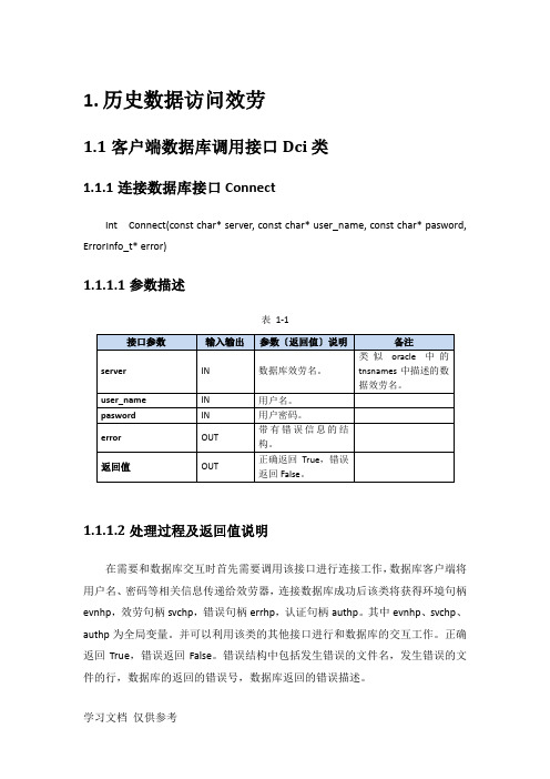
1.历史数据访问效劳1.1客户端数据库调用接口Dci类1.1.1连接数据库接口ConnectInt Connect(const char* server, const char* user_name, const char* pasword, ErrorInfo_t* error)1.1.1.1参数描述表1-11.1.1.2处理过程及返回值说明在需要和数据库交互时首先需要调用该接口进行连接工作,数据库客户端将用户名、密码等相关信息传递给效劳器,连接数据库成功后该类将获得环境句柄evnhp,效劳句柄svchp,错误句柄errhp,认证句柄authp。
其中evnhp、svchp、authp为全局变量。
并可以利用该类的其他接口进行和数据库的交互工作。
正确返回True,错误返回False。
错误结构中包括发生错误的文件名,发生错误的文件的行,数据库的返回的错误号,数据库返回的错误描述。
1.1.1.3调用方法class CDci g_CDci;Error_Info error;Int Retcode;Retcode = g_CDci.Connect(‘HIS’ , ‘hisdb’, ‘hisdb’,error);1.1.2数据库断开连接DisConnectDisConnect(ErrorInfo_t* error)1.1.2.1参数描述表1-21.1.2.2处理过程及返回值说明在程序和数据库交互工作完成以后,需要通知数据库释放为该客户端链接所开的资源,调应该接口可以完成上述工作。
1.1.2.3调用方法class CDci g_CDci;Int retcode;Retcode = g_CDci.DisConnect(error);1.1.3从商用库读取数据1.1.3.1参数描述int CDci::ReadData (IN const char *query, OUT int *rec_num, OUT int *attr_num,OUT struct ColAttr ** attrs,OUT char **buf,ErrorInfo_t* error) int CDci::ReadData (IN const char *query,IN int top_number, OUT int *rec_num, OUT int *attr_num,OUT struct ColAttr ** attrs,OUT char **buf,ErrorInfo_t* error)表1-31.1.3.2处理过程及返回值说明通过该接口,数据库会根据query从数据库读取数据并返回相关数据,rec_num为返回的数据行数,attr_num为返回的属性的个数,attrs为返回的列属性数组的头指针,buf为按照先行后列规那么排列的数据集合,error为接口返回错误结构,接口成功后error为空,接口失败后需要读取error的内容定位数据库错误。
UserMonitor使用指南
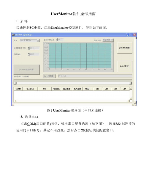
UserMonitor软件操作指南1. 启动:接通控制PC电源,启动UserMonitor控制软件,得到如下画面:图1 UserMonitor主界面(串口未连接)2. 选择串口:点击COM(串口配置)按钮,弹出串口配置选项(如下图),选择RS485连接的使用的串口编号,其它不用改变,然后点击OK按钮关闭配置窗口。
串口配置成功后得到如下画面(如果失败,仍然为第1步的画面),可以进行后续操作,否则需要检查你认为分配给RS485串口的COM编号是否已经被其它设备所占用。
图2 UserMonitor主界面图2中右上方红色半圆圈住部分为监视区域,定时刷新接收到的数据。
3. 回传数据:然后,就可以命令LSS2004回传测试数据,在“回传数据率(秒)”栏,填上你需要LSS2004回传数据的时间间隔(图中填写为2),时间间隔范围为(2~25.5)秒,25.5秒代表手动单次回传。
在左上角的“命令”栏选择“User数据回传”,可以在下方的“接收到的串口Hex数据”消息栏看到LSS2004的反馈信息(十六进制数据串)。
在右上方监视区域中会定时刷新接收到的数据。
4. 数据存储:当接收到的数据达到选取的“显示采样点数”时,UserMonitor会自动记录测试数据,记录的位置和文件名称可以通过Save(存数据)按钮选取。
如果希望采用“PC主控查询”方式,只需要将回传数据的时间间隔设定为25.5,然后选择“User数据回传”即可。
5. 系统设置:首次安装,一般需要对LSS2004的系统信息进行一些设置,点击SysInfo(系统信息)按钮,弹出如下画面:图3 “LSS2004系统信息”对话框下面解释每个参数的意义及作用:MSN:为仪器的出厂序列号,用户不可更改。
永久授权/临时授权:这是厂商出厂设置值,用户不可更改。
其含义为对全部执行采购合同的用户,设定为“永久授权”使用,否则被设定为“临时授权”使用。
授权时间:对应“临时授权”,设定的授权时间。
PM5D数字调音台中文快速指南第一部分

© 2007
版权所有。
3
PM5D/PM5D-RH 快速启动指南 第 1 部分
了解 PM5D 的前后接口并熟悉其布局。
按与模拟调音台相同的方式连接 PM5D 并打开电源。 注意,PM5D-RH 标配没有模拟插入点;所有通道均为动态,您需要附加的 MY 选购卡用于外部插件。
1至48麦克风/线路电平输入 灯接口 用于Studio Manager的USB接口 PSU接口
PM5D/PM5D-RH 快速启动指南 第 1 部分
PM5D/PM5D-RH 快速启动指南分为三个部分。
第 1 部分(简介和设置流程指南);
1) 概述 PM5D 连接、表面布局和主要混音功能。 2) 简要说明储存 / 调用和保存 / 加载过程。 3) 乐队技师如何设置调音台进行特定表演的流程示例。流程深入到D Studio Manager 和 Editor 快速启动);
指南涵盖 PM5D Editor 以及如何通过 Studio Manager 软件实现第 1 部分和第 2 部分中所述的设置和操作。
2
PM5D/PM5D-RH 快速启动指南 第 1 部分
目录
PM5D/PM5D-RH 快速启动指南分为三个部分 ...................................................................................................2 目录 ...................................................................................................................................................................3 了解 PM5D 的前后接口并熟悉其布局 ................................................................................................................4 场景 000;良好的开端.......................................................................................................................................5 以“十个简易步骤”通过 PM5D 初试音效.........................................................................................................5 布局 1:[SEL] 选择键、[CH 1-24]、[CH25-48]、[ST IN 1-4] 和 [FX RTN 1-4] 键 以及 [MIX SEND]/[MIX MASTER] 键 .................................................................................................................6 布局 2:屏幕菜单导航 .......................................................................................................................................7 布局 3:输入通道控制器在哪里? .....................................................................................................................8 布局 4:输出通道控制器在哪里? .....................................................................................................................9 布局 5:多功能编码器 .....................................................................................................................................10 在 PM5D 上进行储存 / 调用和保存 / 加载 ........................................................................................................11 PM5D 设置;流程指南 ....................................................................................................................................12 开始前的调音台准备 ........................................................................................................................................ 13 输入名称并进行转接;计划阶段 ...................................................................................................................... 14 输入名称并进行转接;DISPLAY ACCESS 键..................................................................................................15 施加 +48V 电压至输入端口..............................................................................................................................17 输出转接 .......................................................................................................................................................... 18 内部效果引擎 ...................................................................................................................................................20 矩阵 .................................................................................................................................................................21 图形均衡器,GEQ ...........................................................................................................................................22 USER DEFINED KEYS(用户自定义键) ......................................................................................................23 可分配 /DCA 衰减器.........................................................................................................................................24 提示系统设置 ...................................................................................................................................................25 准备进行试音 ...................................................................................................................................................27
dperf使用方法

dperf使用方法一、安装dperf要使用dperf,首先需要将其安装到您的系统中。
dperf是Go语言编写的,您可以从dperf的GitHub仓库中获取和安装它。
以下是安装dperf的步骤:1. 确保已安装Go语言的运行时环境。
可以通过在终端中运行`go version`命令来检查。
2. 打开终端并执行以下命令以获取dperf的源代码:``````3. 安装成功之后,在终端中执行以下命令以编译和安装dperf:``````4. 安装完成后,您可以在终端中执行`dperf`命令来验证dperf是否已成功安装。
如果您看到dperf的帮助信息,则说明安装成功。
二、配置dperf在运行dperf之前,您需要对其进行一些配置。
以下是配置dperf的主要步骤:1.创建一个配置文件在您的工作目录中创建一个名为`dperf.conf`的文本文件。
这个文件将用于配置dperf的行为。
2. 配置dperf服务器在`dperf.conf`文件中,您需要配置dperf服务器的参数。
以下是一些重要的参数:- `host`:dperf服务器的主机名或IP地址。
- `port`:dperf服务器监听的端口。
- `report_interval`:性能报告的时间间隔。
- `report_file`:性能报告的输出文件。
例如,以下是一个配置示例:```[server]host = localhostport = 8080report_interval = 10sreport_file = /path/to/report.txt```3. 配置dperf客户端在`dperf.conf`文件中,您还需要配置dperf客户端的参数。
以下是一些重要的参数:- `server_host`:dperf服务器的主机名或IP地址。
- `server_port`:dperf服务器监听的端口。
- `duration`:性能测试的持续时间。
- `concurrent_users`:并发用户数。
Maxtor外部硬盘用户手riteria 说明书

3Windows Software SetupWindows Me, 2000 and XP OnlyOnce you have connected the drive to your com-puter as described in section 2, your system will automatically install the proper drivers. Please allow up to two minutes for your system to rec-ognize the drive.Your new drive appears in the same way as your other drives with the name New Volume and a drive letter assigned by the operating system.The assigned letter will vary depending upon the number of other storage devices connected to your computer.If you’re running Windows 2000 or XP , Maxtor suggests re-formatting your drive for best perfor-mance and operation. If you plan to connect this drive to a computer running Windows 98 or ME,you will need to keep the drive in its original for-mat. Further information is provided in the section titled Formatting Your Drive .Your installation is now complete. Further informa-tion is provided in section 4 - Operating Tips .Windows 98SE OnlyOnce you have connected the drive to your com-puter as described in section 2, you will beprompted to insert the Windows 98SE CD-ROM when the product starts up. Y ou will see 4 Version Conflict dialog boxes: Click Y es and keep the exist-ing files. Do not cancel, or the drivers will not load properly. The dialog boxes will only display the first time you install the product and may only show up with the Retail version of Windows 98SE.For proper operation, you must download two updates from Microsoft's website. The updates are titled "Critical Updates Package" and "Storage Supplement Update". Follow the instructions in the section titled "Installing Microsoft updates for Windows 98SE", located on the next page.1394 PCI Adapter CardIf you are using another brand of 1394 card or computer with an integrated 1394 interface and have installed Microsoft’s Critical Updates, you will need to obtain the 1394 drivers from the manufacturer of that card or system.1PreInstallationThank YouThank you for selecting a Maxtor Personal Storage product. Please follow these instructions to take full advantage of its features.Handling PrecautionsIf these handling precautions are not followed,damage to the Personal Storage product may result –which may void your product warranty. Please see the Warranty section for additional information.•DO NOT open the product. Opening the product will void the warranty.•DO NOT bump, jar or drop this device as it may result in loss of data.•DO NOT stack this product more than three units high.•DO NOT set or operate the product on its side without an approved cradle from Maxtor. It may fall over and damage the internal hard drive.•DO NOT disconnect any cables or power while copying files without properly unplugging orunmounting the device via your operating system –as this can result in data loss and possible damage to the internal hard drive.•DO NOT set any liquids or drinks on the product -as they will damage the internal electronics.Hardware and Operating System Requirements for Windows PC•Pentium II-class or higher•32 MB of RAM or more as required by Windows •Available FireWire/1394/i.LINK (OHCI-compliant) port •Internet connection (for system updates)•Windows 98 Second Edition, Windows Millennium Edition, Windows 2000 or Windows XPKit ComponentsThe Maxtor Personal Storage product comes complete with the components shown here.Please familiarize yourself with each of these items prior to installation.Personal StoragePower Adapter1394 Cable2Hardware InstallationPersonal Storage InstallationTo connect your new Maxtor Personal Storage product to your computer, please follow these simple steps.If these steps are not performed in order, your product may not function properly.Power Cord Connections1.Ensure that your computer is on and running oneof the required operating systems.2.Plug the four-pin male connector with the flatside facing up into the back of the product’s DC power-in connector (Figure 1).3.Connect the female end of the electric cord intothe power adapter (Figure 2).4.Plug the male connector from the power adapterinto power outlet.1394 Data Cable Connections1.Plug one end of the translucent 1394 cable intoany available 1394 port on your computer.2.Plug the other end of the translucent 1394 cableinto either of the 1394 connections on the product (Figure 3).Figure 31394 Interface Cable Hook-upFigure 2Power Adapter Hook-upFigure 1Power Connector Hook-up4Operating TipsDisconnecting the ProductRight click on the Windows Unplug or EjectHardware icon in your system icon tray located at the bottom right corner of your screen.Reattaching the ProductTo reattach the Personal Storage product, simply re-insert the 1394 cable into the product and your com-puter. Make sure the product is getting power.Spin down Power ManagementTo minimize the power consumption of your drive while your computer is on, you can take advantage of the power management feature supported on the FireWire interface and Windows 2000 and XP . The following table shows where to find the power man-agement feature in each operating system version.and youroperating system is:try this first:Windows XPClick on Start.Go to Settings.Go to Control Panel. Select Power Options.Windows 2000Click on Start.Go to Settings.Go to Control Panel. Select Power Options.Windows Millennium Spinning down external hard drives not Editionsupported by operating system.Windows 98 Second Spinning down external hard drives not Editionsupported by operating system.Continued4Operating Tips cont.Spin down Power Management cont.The power management feature sets the drive to automatically use less power after a predetermined period of time of inactivity. This is sometimes referred to as spin down since the drive’s internal mechanical disks stop spinning. When the drive is in the spin down mode, the green power light will remain on and the amber activity light will be off.When your computer is powered off, you can choose to do one of the following:• Leave the drive plugged in all the time. The device is designed to run with the power on at all times.• Plug the drive’s power supply into a power strip with an on/off switch so you can turn your drive’s power off to further conserve power.Make sure you remove the drive from your computer through the operating system before you disconnect it or turn off the drive’s power. Shutting off the drive’s power while your computer is running can cause the loss or corruption of data.Installing Microsoft updates for Windows 98SE(Windows 98SE only)Your system must be connected to the internet and have a 1394 interface installed (built-in or plug-in interface card) to install these two updates.• Click on the Start button located on your Windows toolbar.• Select the Windows Update option from thismenu. (This will launch your Internet browser to the appropriate Microsoft web site for your Operating System in the language that you are using).• Click on the Product Updates link from this Microsoft web site. This option will examine your system and prompt you to download the necessary updates.A new web page will appear titled Select Software .There should be a checkmark next to the option titled Critical Updates Package .Click on the Download button near the top of this web page. On the next web page, click Start Download . Accept the license agreement thatappears next. Your system will download the update and install it. Restart (reboot) your system whenprompted to do so.A window will display Windows 98 Setup – Updating System Settings .To install Microsoft's Storage Supplement, go to the web site: /windows98 and search for "1394." You should see an article titled "Windows 98 Second Edition 1394 Storage Supplement : [Windows 98, 1394, storage]."Click on the link and follow the instructions to down-load and install the file. Restart (reboot) your system when prompted to do so.Your system is now updated for proper operation with your 1394 external disk drive.Formatting Your DriveOptional for Windows 98/2000/Me/XPY our Maxtor Personal Storage 3000 drive was format-ted at the factory with the Windows FAT32 file system.This file system is compatible with Mac OS 9 and recent versions of the Windows operating system.The FAT32 file system limits any file to a maximum size of 4 GB. If you are running Windows 98 or Me,consider upgrading to Windows 2000 or XP to take advantage of the NTFS file system.If you are running either the Windows 2000 or XP operating system, consider reformatting your drive to the NTFS file system. The NTFS file system provides several advantages, including support for very large files. See the following section titled: Formatting Your Drive with NTFS.Your new drive will display a drive capacity that is slightly less than the capacity stated on the box. This is normal. For a complete explanation, see the sec-tion titled: My computer shows less drive capacity than on the drive box label.Formatting Your Drive with NTFSThis section describes how to format your drive with the NTFS file system for Windows 2000 or XP .Formatting the drive destroys all data contained on that drive. Make a backup copy of all your data before formatting your drive.To format the drive for NTFS1.Select Start ➔Settings ➔Control Panel .2.Double-click Administrative Tools .3.Double-click Computer Management .4.Double-click Disk Management (located underthe Storage icon).5.Right-click on the icon for your new drive in thewindow that appears.FAT32 should be listed in the column labeled File System .6.Select Format from the menu.7.Select NTFS in the File System field.8.Click OK when you are ready to format your drive.Formatting time varies based on your system speed, and the drive’s capacity.My computer shows less drive capacity than on the box labelHard Drive Manufacturer Capacity DefinitionsThe listed capacity is an unformatted (raw) capacity.After partitioning and formatting, actual storagecapacities may vary depending on the operating system and configuration. Maxtor adheres to the National Institute of Standards and Technology (NIST:) definition of Megabyte and Gigabyte.Examples:•1 MB = One Million Bytes •1 GB = One Billion BytesOperating System and BIOS Capacity DefinitionsStorage devices are marketed and sold in terms of decimal (base 10) capacity. In decimal terms, one Gigabyte (GB) is equal to one billion bytes. Most BIOS’s follow this definition as well. However, many operating systems use the binary (base 2) numbering system. That would be two to the thirtieth power, or 1,073,741,824 bytes equals one-Gigabyte.According to the NIST standard, an 80 GB hard drive would contain eighty billion bytes. 80,000,000,000bytes divided by 1,000,000,000 bytes equals eighty decimal Gigabytes. In binary terms, 80,000,000,000bytes would be divided by 1,073,741,824 for a total of 74.5 binary GB. However, there are still 80 billion bytes on the drive in either case.To display the correct capacity of your drive:• Right-click the My Computer icon and select Explore . This opens a new window listing all the disk drives on your system.• Right-click on the external hard drive and select Properties . An information dialog box appears displaying the drive’s capacity in total bytes.5Product RegistrationTake Advantage of the Benefits!By registering your new Personal Storage product,you’ll have the option to receive product updates,special offers,and important information about other data storage solutions from Maxtor.Simply point your web browser to: – go to the product registration page, and complete the short questionnaire.Maxtor’s warranty obligations are limited to the terms set forth:Maxtor warrants only to the original consumer purchaser that new Maxtor Personal Storage products will be free from defects in material and workmanship for 1 year from the date of original purchase.For a replacement Personal Storage product, the warranty on the replacement device is the remainder of the warranty on the original device or 90 days, whichever is longer. If you discover a defect, Maxtor will, at its option, repair or replace the product at no charge to you, provided you return it during the warrantyperiod, with transportation charges prepaid, to Maxtor in Ireland,Singapore or the USA.Personal Storage products must be properly packaged in Maxtor packaging or Maxtor approved packaging to obtain warranty ser-vice. Before returning a Maxtor product, please contact Maxtor at: +353 1 204 1111 (in Europe) or 1-800-2MAXTOR (in U.S.) to obtain a Return Material Authorization (RMA) number. A copy of the receipt or a bill of sale bearing the appropriate Maxtor serial number and model number may be required for warranty service.The warranty applies only to the Maxtor products that can be identified by the Maxtor trademark, trade name, serial number or logo affixed to them. Maxtor does not warrant any product that is not manufactured by, for or with permission from Maxtor.This warranty is not applicable to: Abuse, unreasonable use,mistreatment, or neglect; Damage caused during installation of the Product; Damage caused by the equipment or system with which the product is used; Damage caused by modification or repair not made or authorized by Maxtor; Product whose Maxtor Serial Number has been removed or defaced; Damage caused by liquids in the product case; Damage to the products’ inter-face or power connectors; Damage caused by use of non-Maxtor packaging; Damage caused by improper or improperly used packaging; Products that are determined to be stolen.THIS WARRANTY AND REMEDIES SET FORTH ABOVE ARE EXCLUSIVE AND IN LIEU OF ALL OTHERS, WHETHER ORAL OR WRITTEN, EXPRESSED OR IMPLIED. MAXTOR SPECIFI-CALLY DISCLAIMS ANY AND ALL IMPLIED WARRANTIES,INCLUDING, WITHOUT LIMITATION, WARRANTIES OF MER-CHANTABILITY AND FITNESS FOR A PARTICULAR PURPOSE AND AGAINST INFRINGEMENT. ADDITIONALLY , MAXTOR DOES NOT WARRANT THAT THE PERSONAL STORAGEINSTALLATION SOFTWARE DISTRIBUTED IN THE PERSONAL STORAGE KIT WILL MEET YOUR REQUIREMENTS NOR THE PERFORMANCE OR RESULTS THAT THE OPERATION OF THE PROGRAM WILL BE UNINTERRUPTED OR ERROR FREE.No Maxtor dealer, agent or employee is authorized to make any modification, extension or addition to this warranty.MAXTOR IS NOT RESPONSIBLE FOR SPECIAL, INCIDENTAL,INDIRECT OR CONSEQUENTIAL DAMAGES RESULTINGFROM ANY BREACH OF WARRANTY , OR UNDER ANY OTHER LEGAL THEORY , INCLUDING BUT NOT LIMITED TO LOSS OF DATA, LOSS OF PROFITS, DOWNTIME, GOODWILL, DAMAGE OR REPLACEMENT OF EQUIPMENT AND PROPERTY , AND ANY COSTS OF RECOVERING, PROGRAMMING OR REPRO-DUCING ANY PROGRAM OR DATA STORED IN OR USEDWITH MAXTOR DISK DRIVES OR MAXTOR PERSONAL STOR-AGE PRODUCTS CONTAINING MAXTOR DISK DRIVES or any software product distributed therewith.Some states/jurisdictions do not allow the exclusion or limitation of incidental or consequential damages or exclusions of implied warranties, so the above limitations or exclusions may not apply to you. This warranty gives you specific legal rights, and you may also have other rights that vary from jurisdiction to jurisdiction.Maxtor may make changes or improvements in the product(s)described in this publication at any time and without notice.This product tested to comply with FCC standards for home or office use.Copyright © 2002 Maxtor Corporation. All rights reserved.Printed in the U.S.A. 9/02. Maxtor ®is a registered trademark of Maxtor Corporation. Other brands or products are trademarks or registered trademarks of their respective holders.Maxtor p/n: 20201100/ANotes on using your drive with the Windows operating systemNote 1:On disks larger than 64GB (Windows 98SE),both the FDISK and FORMAT utilities perform their functions properly, but they display an incorrect disk size on the screen. A similar problem has been observed with Windows ME at larger disk sizes(starting above 99GB). Further information is available on Microsoft’s support web site at:/support/kb articles/Q263/0/44.ASP/support/kb/articles/Q263/0/45.ASPNote 2:The FDISK utility may not run properly after an external disk drive has been disconnected and reconnected. It is recommended the user reboot the computer before running FDISK.Note 3:Neither the ScanDisk nor Defrag utilities will operate on drive partitions larger than 127GB. Further information is available on Microsoft’s support web site at:/support/kb/articles/Q184/0/06.ASPThird party utilities, including Norton System Works 2000 and 2002, can be used to replace the function-ality of the ScanDisk and Defrag utilities.Windows 98SEWindows ME Windows 2000, XP File System:FAT32, NTFS FAT32 Operates properly withpartition up to 160GB FAT32 operates properly with partition up to 160GB FAT32 and NTFS operate properly with partition up to 160GB FDISK,FORMATFDISK and FORMAT – two known bugs,see Notes 1 and 2FDISK and FORMAT – one known bug, see Note 1NTFS operatesproperly with partition up to 160GB Cannot format partition >32GB in FAT32Defrag and ScanDiskDefrag and ScanDisk limited to partition <127GB, see Note 3Operates properly with partition up to 160GB Operates properly with partition up to 160GBProduct Warranty。
Oracle OBTR安装指南说明书

Oracle OBTR Installer Index Oracle Banking Treasury Management Release 14.5.0.0.0[May] [2021]Table of Contents1.ABOUT THE MANUAL ................................................................................................................................. 1-11.1I NTRODUCTION........................................................................................................................................... 1-1 1.2A UDIENCE .................................................................................................................................................. 1-1 1.3A BBREVIATIONS AND A CRONYMS.............................................................................................................. 1-12.INDEX .............................................................................................................................................................. 2-12.1S ECURITY G UIDELINES............................................................................................................................... 2-1 2.2E NVIRONMENT S ETUP ................................................................................................................................ 2-1 2.3S UPPORT FOR E XTENSIBILITY..................................................................................................................... 2-2 2.4I NSTALLER I NSTALLATION ......................................................................................................................... 2-3 2.5I NSTALLATION............................................................................................................................................ 2-3 2.6M AINTENANCE ........................................................................................................................................... 2-3 2.7I NSTALLER U TILITIES ................................................................................................................................. 2-3 2.8T ROUBLESHOOTING.................................................................................................................................... 2-31. About the Manual 1.1 IntroductionThis manual is designed to help acquaint you with the installation of Oracle Banking Treasury Management.1.2 AudienceThis manual is intended for the following User/User Roles:The user of this manual is expected to have basic understanding of Application servers like Oracle Weblogic, IBM Websphere and Oracle Database.1.3 Abbreviations and AcronymsThis guide may refer to the following abbreviations:2. Index 2.1 Security GuidelinesThe user of this manual should ensure security guidelines for this release of OBTR are adhered to as mentioned in the Security Guide document. This is a pre-requisite before proceedingfurther.2.2 Environment SetupThis section helps you get an outline of the chapters included in the Installation Manuals and provides a summary of each chapter. You can identify the chapters containing the details of each activity that you will perform during Oracle Banking Treasury Management installation.The Installation Manuals are organized as follows:2.3 Support for Extensibility2.4 Installer InstallationInstaller support installation of Oracle FLEXCUBE in two modes Graphical mode and silent mode.2.5 Installation2.6 Maintenance2.7 Installer Utilities2.8 TroubleshootingOracle OBTR Installer IndexMay [2021]Version 14.5.0.0.0Oracle Financial Services Software LimitedOracle ParkOff Western Express HighwayGoregaon (East)Mumbai, Maharashtra 400 063IndiaWorldwide Inquiries:Phone: +91 22 6718 3000Fax: +91 22 6718 3001https:///industries/financial-services/index.htmlCopyright © [2020], [2021]Oracle and/or its affiliates. All rights reserved.Oracle and Java are registered trademarks of Oracle and/or its affiliates. Other names may be trademarks of their respective owners.U.S. GOVERNMENT END USERS: Oracle programs, including any operating system, integrated software, any programs installed on the hardware, and/or documentation, delivered to U.S. Government end users are "commercial computer software" pursuant to the applicable Federal Acquisition Regulation and agency-specific supplemental regulations. As such, use, duplication, disclosure, modification, and adaptation of the programs, including any operating system, integrated software, any programs installed on the hardware, and/or documentation, shall be subject to license terms and license restrictions applicable to the programs. No other rights are granted to the U.S. Government.This software or hardware is developed for general use in a variety of information management applications. It is not developed or intended for use in any inherently dangerous applications, including applications that may create a risk of personal injury. If you use this software or hardware in dangerous applications, then you shall be responsible to take all appropriate failsafe, backup, redundancy, and other measures to ensure its safe use. Oracle Corporation and its affiliates disclaim any liability for any damages caused by use of this software or hardware in dangerous applications.This software and related documentation are provided under a license agreement containing restrictions on use and disclosure and are protected by intellectual property laws. Except as expressly permitted in your license agreement or allowed by law, you may not use, copy, reproduce, translate, broadcast, modify, license, transmit, distribute, exhibit, perform, publish or display any part, in any form, or by any means. Reverse engineering, disassembly, or decompilation of this software, unless required by law for interoperability, is prohibited.The information contained herein is subject to change without notice and is not warranted to be error-free. If you find any errors, please report them to us in writing.This software or hardware and documentation may provide access to or information on content, products and services from third parties. Oracle Corporation and its affiliates are not responsible for and expressly disclaim all warranties of any kind with respect to third-party content, products, and services. Oracle Corporation and its affiliates will not be responsible for any loss, costs, or damages incurred due to your access to or use of third-party content, products, or services.。
PMD-1608FS user guide

PMD-1608FSPersonal Measurement Device™ brandUSB-basedAnalog and Digital I/O ModuleUser's GuideDocument Revision 6, May, 2005© Copyright 2005, Measurement Computing Corporation™Your new Measurement Computing product comes with a fantastic extra — Management committed to your satisfaction!Refer to /execteam.html for the names, titles, and contact information of each key executive at Measurement Computing.Thank you for choosing a Measurement Computing product—and congratulations! You own the finest, and you can now enjoy the protection of the most comprehensive warranties and unmatched phone tech support. It’s the embodiment of our two missions:To offer the highest-quality, computer-based data acquisition, control, and GPIB hardware and software available—at the best possible price.To offer our customers superior post-sale support—FREE. Whether providing unrivaled telephone technical and sales support on our latest product offerings, or continuing that same first-rate support on older products andoperating systems, we’re committed to you!Lifetime warranty: Every hardware product manufactured by Measurement Computing Corporation is warranted against defects in materials or workmanship for the life of the product. Products found defective are repaired or replaced promptly. Lifetime Harsh Environment Warranty®: We will replace any product manufactured by Measurement Computing Corporation that is damaged (even due to misuse) for only 50% of the current list price. I/O boards face some tough operating conditions some more severe than the boards are designed to withstand. When a board becomes damaged, just return the unit with an order for its replacement at only 50% of the current list price. We don’t need to profit from your misfortune. By the way, we honor this warranty for any manufacturer’s board that we have a replacement for.30 Day Money Back Guarantee: You may return any Measurement Computing Corporation product within 30 days of purchase for a full refund of the price paid for the product being returned. If you are not satisfied, or chose the wrong product by mistake, you do not have to keep it. Please call for an RMA number first. No credits or returns accepted without a copy of the original invoice. Some software products are subject to a repackaging fee.These warranties are in lieu of all other warranties, expressed or implied, including any implied warranty of merchantability or fitness for a particular application. The remedies provided herein are the buyer’s sole and exclusive remedies. Neither Measurement Computing Corporation, nor its employees shall be liable for any direct or indirect, special, incidental or consequential damage arising from the use of its products, even if Measurement Computing Corporation has been notified in advance of the possibility of such damages.Trademark and Copyright InformationPersonal Measurement Device brand, TracerDAQ, Universal Library, Insta Cal, Harsh Environment Warranty, Measurement Computing Corporation, and the Measurement Computing logo, are either trademarks or registered trademarks of Measurement Computing Corporation.SoftWIRE is a registered trademark of SoftWIRE Technology, Inc.Windows, Microsoft, and Visual Studio are either trademarks or registered trademarks of Microsoft Corporation. LabVIEW is a trademark of National Instruments. All other trademarks are the property of their respective owners.Information furnished by Measurement Computing Corporation is believed to be accurate and reliable. However, no responsibility is assumed by Measurement Computing Corporation neither for its use; nor for any infringements of patents or other rights of third parties, which may result from its use. No license is granted by implication or otherwise under any patent or copyrights of Measurement Computing Corporation.All rights reserved. No part of this publication may be reproduced, stored in a retrieval system, or transmitted, in any form by any means, electronic, mechanical, by photocopying, recording, or otherwise without the prior written permission of Measurement Computing Corporation.NoticeMeasurement Computing Corporation does not authorize any Measurement Computing Corporation product for use in life support systems and/or devices without the written approval of the CEO of Measurement Computing Corporation. Life support devices/systems are devices or systems which, a) are intended for surgical implantation into the body, or b) support or sustain life and whose failure to perform can be reasonably expected to result in injury. Measurement Computing Corporation products are not designed with the components required, and are not subject to the testing required to ensure a level of reliability suitable for the treatment and diagnosis of people.Table of ContentsPrefaceAbout this User's Guide (vi)What you will learn from this user's guide (vi)Conventions in this user's guide (vi)Where to find more information (vii)Chapter 1Introducing the PMD-1608FS...........................................................................................................1-1 PMD-1608FS block diagram..........................................................................................................................1-2 Software features............................................................................................................................................1-2 Connecting a PMD-1608FS to your computer is easy....................................................................................1-3 Chapter 2Installing the PMD-1608FS...............................................................................................................2-1 What comes with your PMD-1608FS shipment?...........................................................................................2-1 Hardware.......................................................................................................................................................................2-1 Software.........................................................................................................................................................................2-1 Documentation...............................................................................................................................................................2-2 Unpacking the PMD-1608FS.........................................................................................................................2-2 Installing the software....................................................................................................................................2-2 Installing the hardware...................................................................................................................................2-2 Chapter 3Functional Details.............................................................................................................................3-1 Theory of operation - analog input acquisition modes...................................................................................3-1 Software paced mode.....................................................................................................................................................3-1 Continuous scan mode...................................................................................................................................................3-1 Burst scan mode.............................................................................................................................................................3-1 External components......................................................................................................................................3-2 USB connector...............................................................................................................................................................3-2 LED...............................................................................................................................................................................3-2 Screw terminal wiring....................................................................................................................................................3-3 Main connector and pin out...........................................................................................................................................3-3 Analog input terminals (CH0 IN - CH7 IN)...................................................................................................................3-4 Digital I/O terminals (DIO0 to DIO7)............................................................................................................................3-5 Power terminals.............................................................................................................................................................3-6 Ground terminals...........................................................................................................................................................3-6 Calibration terminal.......................................................................................................................................................3-7 Counter terminal............................................................................................................................................................3-7 SYNC terminal..............................................................................................................................................................3-7 Trigger terminal.............................................................................................................................................................3-7 Accuracy.........................................................................................................................................................3-7 Gain queue....................................................................................................................................................3-10 Synchronizing multiple units........................................................................................................................3-10 Chapter 4 Specifications....................................................................................................................................4-1 Analog input section.......................................................................................................................................4-1 Digital input/output.........................................................................................................................................4-2 External trigger...............................................................................................................................................4-2 External clock input/output.............................................................................................................................4-3 Counter section...............................................................................................................................................4-3 Memory..........................................................................................................................................................4-3PMD-1608FS User's GuideMicrocontroller...............................................................................................................................................4-4 Power..............................................................................................................................................................4-4 General...........................................................................................................................................................4-4 Environmental................................................................................................................................................4-4 Mechanical.....................................................................................................................................................4-4 Main connector and pin out............................................................................................................................4-5Preface About this User's GuideWhat you will learn from this user's guideThis user's guide explains how to install, configure, and use the PMD-1608FS so that you get the most out of its USB data acquisition features.This user's guide also refers you to related documents available on our web site, and to technical support resources that can also help you get the most out of the PMD-1608FS.Conventions in this user's guideFor more information on …Text presented in a box signifies additional information and helpful hints related to the subject matter you are reading.Caution!Shaded caution statements present information to help you avoid injuring yourself and others, damaging your hardware, or losing your data.<#:#> Angle brackets that enclose numbers separated by a colon signify a range of numbers, such as those assigned to registers, bit settings, etc.bold text Bold text is used for the names of objects on the screen, such as buttons, text boxes, and check boxes. For example:1.Insert the disk or CD and click the OK button.italic text Italic text is used for the names of manuals and help topic titles, and to emphasize a word or phrase.For example:The Insta Cal® installation procedure is explained in the DAQ Software Quick Start.Never touch the exposed pins or circuit connections on the boardPMD-1608FS User's Guide About this User's GuideWhere to find more informationThe following electronic documents provide information that can help you get the most out of your Personal Measurement Device™ brand PMD-1608FS.MCC's Specifications: PMD-1608FS (the PDF version of Chapter 4 in this guide) is available on our web site at /pdfs/PMD-1608FS.pdf.MCC's DAQ Software Quick Start is available on our web site at/PDFmanuals/DAQ-Software-Quick-Start.pdf.MCC's Guide to Signal Connections is available on our web site at/signals/signals.pdf.MCC's Universal Library User's Guide is available on our web site at/PDFmanuals/sm-ul-user-guide.pdf.MCC's Universal Library Function Reference is available on our web site at/PDFmanuals/sm-ul-functions.pdf.MCC's Universal Library for LabVIEW™ User’s Guide is available on our web site at /PDFmanuals/SM-UL-LabVIEW.pdf.MCC's Guide to Signal Connections is available on our web site at/signals/signals.pdf.PMD-1608FS User’s Guide (this document) is available on our web site at/PDFmanuals/PMD-1608FS.pdf.Chapter 1 Introducing the PMD-1608FSThis user's guide contains all of the information you need to connect the PMD-1608FS to your computer and to the signals you want to measure. The PMD-1608FS is part of the Personal Measurement Device™ brand of USB-based data acquisition products.The PMD-1608FS is a USB 2.0 full-speed device supported under Microsoft® Windows® 98 (2ndedition), Windows ME, Windows 2000, and Window XP. It is designed for USB 1.1 ports, and was tested for full compatibility with both USB 1.1 and USB 2.0 ports.The PMD-1608FS offers true simultaneous sampling of up to eight channels of 16-bit single-endedanalog input. This is accomplished through the use of one A/D converter per channel. The range of each channel is independently configurable via software. Eight digital IO lines are independently selectable as input or output. A 32-bit counter is capable of counting TTL pulses. The PMD-1608FS is powered by the +5 volt USB supply from your computer. No external power is required.A SYNC (synchronization) control line allows you to synchronize two PMD-1608FS modules together toacquire data synchronously from 16 analog inputs.The PMD-1608FS is shown in Figure 1-1. I/O connections are made to the screw terminals located along each side of the PMD-1608FS.Figure 1-1. PMD-1608FSPMD-1608FS User's Guide Introducing the PMD-1608FS PMD-1608FS block diagramPMD-1608FS functions are illustrated in the block diagram shown here. S c r e w t e r m i n a l I /O c o n n e c t o r SPI 8DIO G= 1, 2, 5, 10A/D 0A/D 1A/D 2A/D 3A/D 4A/D 5A/D 6A/D 732-bitEvent Counter1 channelUSB Microcontroller SYNC1632k x 16SRAM USBFull-speedUSB 2.0CompliantInterface 1616S c r e w t e r m i n a l I /O c o n n e c t o r CAL TRIG_INCALFigure 1-2. PMD-1608FS Functional Block DiagramSoftware featuresThe following software ships with the PMD-1608FS free of charge.Insta Cal installation, calibration, and test utilityTracerDAQ™ suite of virtual instrumentsSoftWIRE® for Visual Studio® .NET graphical programmingMCC DAQ Components for Visual Studio .NET (installed with SoftWIRE® for VS .NET)Universal Library Universal Library for LabVIEWFor information on the features of Insta Cal, TracerDAQ, and SoftWIRE, refer to the DAQ Software Quick Start booklet that shipped with the PMD-1608FS.PMD-1608FS User's Guide Introducing the PMD-1608FSConnecting a PMD-1608FS to your computer is easy Installing a data acquisition device has never been easier.The PMD-1608FS relies upon the Microsoft Human Interface Device (HID) class drivers. The HID class drivers ship with every copy of Windows that is designed to work with USB ports. We use the Microsoft HID because it is a standard, and its performance delivers full control and maximizes data transfer rates for your PMD-1608FS. No third-party device driver is required.The PMD-1608FS is plug-and-play. There are no jumpers to position, DIP switches to set, or interrupts to configure.You can connect the PMD-1608FS before or after you install the software, and without powering down your computer first. When you connect an HID to your system, your computer automaticallydetects it and configures the necessary software. You can connect and power multiple HIDperipherals to your system using a USB hub.You can connect your system to various devices using a standard four-wire cable. The USB connector replaces the serial and parallel port connectors with one standardized plug and portcombination.You do not need a separate power supply module. The USB automatically delivers the electrical power required by each peripheral connected to your system.Data can flow two ways between a computer and peripheral over USB connections.Chapter 2 Installing the PMD-1608FSWhat comes with your PMD-1608FS shipment?As you unpack your PMD-1608FS, verify that the following components are included.HardwarePMD-1608FSUSB cable (2 meter length)SoftwareThe Measurement Computing Data Acquisition Software CD contains the following software:Insta Cal installation, calibration, and test utilityTracerDAQ suite of virtual instrumentsSoftWIRE for VS .NETSoftWIRE MCC DAQ Components for .NETDocumentationIn addition to this hardware user's guide, you should also receive the DAQ Software Quick Start(available in PDF at /PDFmanuals/DAQ-Software-Quick-Start.pdf). Please read this booklet completely before installing any software and hardware.Unpacking the PMD-1608FSAs with any electronic device, you should take care while handling to avoid damage from staticelectricity. Before removing the PMD-1608FS from its packaging, ground yourself using a wrist strap or by simply touching the computer chassis or other grounded object to eliminate any stored static charge.If your PMD-1608FS is damaged, notify Measurement Computing Corporation immediately by phone, fax, or e-mail:Phone: 508-946-5100 and follow the instructions for reaching Tech Support.Fax: 508-946-9500 to the attention of Tech SupportEmail: techsupport@Installing the softwareRefer to the DAQ Software Quick Start for instructions on installing the software on the Measurement Computing Data Acquisition Software CD. This booklet is available in PDF at/PDFmanuals/DAQ-Software-Quick-Start.pdf.Installing the hardwareBe sure you are using the latest system softwareBefore you connect the PMD-1608FS, make sure that you are using the latest versions of the USBdrivers.Before installing the PMD-1608FS, download and install the latest Microsoft Windows updates. Inparticular, when using Windows XP, make sure you have XP Hotfix KB822603 installed. This update is intended to address a serious error in Usbport.sys when you operate a USB device. You can run Windows Update or download the update from /downloads/details.aspx?familyid=733dd867-56a0-4956-b7fe-e85b688b7f86&displaylang=en. For more information, refer to the MicrosoftKnowledge Base article "Availability of the Windows XP SP1USB1.1and2.0update." This article is available at /?kbid=822603.To connect the PMD-1608FS to your system, turn your computer on, and connect the USB cable to a USB port on your computer or to an external USB hub that is connected to your computer. The USB cable provides power and communication to the PMD-1608FS.The PMD-1608FS installs as a composite device with separate devices attached. When you connect the PMD-1608FS for the first time, Found New Hardware popup balloons (Windows XP) or dialogs (other Windows version) open as each PMD-1608FS interface is detected.It is normal for multiple dialogs to open when you connect the PMD-1608FS for the first time. For additional information, refer to the "Notes on installing and using the PMD-1608FS" that was shipped with the PMD-1608FS.When the last balloon or dialog closes, the installation is complete. The LED on the PMD-1608FS should flash and then remain lit. This indicates that communication is established between the PMD-1608FS and your computer.Caution!Do not disconnect any device from the USB bus while the computer is communicating with the PMD-1608FS, or you may lose data and/or your ability to communicate with the PMD-1608FS.If the LED turns offIf the LED is lit but then turns off, the computer has lost communication with the PMD-1608FS. To restore communication, disconnect the USB cable from the computer, and then reconnect it. This should restore communication, and the LED should turn back on.Chapter 3 Functional DetailsTheory of operation - analog input acquisition modes The PMD-1608FS can acquire analog input data in three basic modes – software paced, continuous scan, and burst scan.Software paced modeYou can acquire one analog sample at a time in software paced mode. You initiate the A/D conversion by calling a software command. The analog value is converted to digital data and returned to the computer.You can repeat this procedure until you have the total number of samples that you want from onechannel.The maximum throughput sample rate in software paced mode is system-dependent.Continuous scan modeYou can acquire data from up to eight channels simultaneously in continuous scan mode. The analog data is continuously acquired, converted to digital values, and written to an on-board FIFO buffer on thePMD-1608FS until you stop the scan. The FIFO buffer is serviced in blocks as the data is transferred from the PMD-1608FS FIFO buffer to the memory buffer on your computer.The maximum sampling rate is an aggregate rate, where the total sample rate for all channels is 100 kS/s divided by the number of channels, with a maximum rate of 50 kS/s for any channel. Using this equation, you can acquire data with the PMD-1608FS from one channel at 50 kS/s, two channels at 50 kS/s each, four channels at 25 kS/s each, and so on, up to eight channels at 12.5 kS/s each. You can start acontinuous scan with either a software command or with an external hardware trigger event.Burst scan modeIn burst scan mode, you can acquire data with the PMD-1608FS using the full capacity of its 32 K sample FIFO. The acquired data is then read from the FIFO and transferred to a user buffer in your computer.You can initiate a single acquisition sequence of one, two, four, or eight channels by either a software command or an external hardware trigger.Burst scans are limited to the depth of the on-board memory, as the data is acquired at a rate faster than it can be transferred to the computer. The maximum sampling rate is an aggregate rate, where the total acquisition rate for all channels is 200 kS/s divided by the number of channels, with a maximum rate of50 kS/s for any channel. The maximum rate that you can acquire data using burst scan mode is 50 kS/seach for one, two, or four channels, and 25 kS/s each for eight channels.External componentsThe PMD-1608FS has the following external components, as shown in Figure 3-1. USB connector LEDScrew terminal banks (2)USBconnector / cableScrew terminal Pins 21 to 40Screw terminal Pins 1 to 20LEDFigure 3-1. PMD-1608FS Personal Measurement DeviceUSB connectorThe USB connector is on the right side of the PMD-1608FS. This connector provides +5 V power and communication. The voltage supplied through the USB connector is system-dependent, and may be less than 5 V. No external power supply is required.LEDThe LED on the front of the PMD-1608FS indicates the communication status. It uses up to 5 mA of current and cannot be disabled. explains the function of the PMD-1608FS LED.Table 3-1Table 3-1 LED IlluminationWhen the LED is… It indicates…Steady greenThe PMD-1608FS is connected to a computer or external USB hub. Blinks continuously Data is being transferred.Blinks three times Initial communication is established between the PMD-1608FS and the computer. Blinks at a slow rateThe analog input is configured for external trigger. The LED stops blinking and illuminates steady green when the trigger is received.Screw terminal wiringThe PMD-1608FS has two rows of screw terminals—one row on the top edge of the housing, and one row on the bottom edge. Each row has 20 connections. Pin numbers are identified in Fi .gure 3-2Figure 3-2. PMD-1608FS screw terminal pin numbersPin 1Pin 20Pin 21Pin 40Screw terminal – pins 1-20The screw terminals on the top edge of the PMD-1608FS (pins 1 to 20) provide the following connections: Eight analog input connections (CH0 IN to CH7 IN ) Eleven analog ground connections (AGND )One calibration output terminal (CAL )Screw terminal – pins 21-40The screw terminals on the bottom edge of the PMD-1608FS (pins 21 to 40) provide the following connections: Eight digital I/O connections (DIO0 to DIO7) One external trigger source (TRIG_IN )One external event counter connection (CTR ) One power connection (PC+5 V )One SYNC terminal for external clocking and multi-unit synchronization (SYNC )Eight ground connections (GND )Main connector and pin outConnector type Screw TerminalWire gauge range16 AWG to 30 AWG20191817C A L 1615141312111098A GN D A G N D A G N D A G N D C H 7 I N A G N D C H 6 I N A G N D 5 I N A G N D C H 4 I N A G N D 7C H 3 I N 6A G N D 5C H 2 I N 4A G N D 3C H 1 I N 2A G N D 1C H 0 I NC H G ND 40P C +5V 39C T R 38T R I G _I N 37S Y N C 36D I O 735G N D 34D I O 633G N D 32D I O 531G N D 30D I O 429G N D 28D I O 327G N D 26D I O 225G N D 24D I O 123G N D 22D I O 021Analog input terminals (CH0 IN - CH7 IN)You can connect up to eight analog input connections to the screw terminal containing pins 1 to 20 (CH0IN through CH7 IN .) Refer to the pinout diagram on page 3-3 for the location of these pins. Werecommend that you connect unused analog input terminals to ground terminals during operation. For example, if you are not using terminal 15 (CH7 IN), connect this terminal to terminal 16 (AGND). Input configurationAll of the analog input channels are configured for single-ended input mode. Each analog signal is referenced to signal ground (AGND), and requires two wires: The wire carrying the signal to be measured connects to CH# IN.The second wire connects to AGND.The input voltage ranges are ±10 V, ±5 V, ±2.0 V, ±1.0 V. The following image illustrates a typical single-ended measurement connection.。
雷迪 手册

DM_REDBOX简明操作程序1. 启动PDA首先将GETAC底部软盖内的On/Off开关机开关转换到On位置开机。
然后按显示屏下方的电源键启动GETAC运行。
2. 启动DM分析软件点击WINDOWS开始图标,在下拉菜单内点击“DM防腐层检测评价软件”,启动DM,分析软件。
3. 检测参数设置初始启动界面有四个图标:(1)“新建数据”:用于在检测开始前设置检测参数(2)“打开旧数据”:用于查看存储数据。
(3)“关于雷迪”:用于查看雷迪公司联系信息。
(4)“退出系统”:用于退出程序。
点击“新建数据”,出现频率选择界面:一般地,默认的“频率数”是双频,“频率1”一般选定为DM超低频频率,“频率2”一般根据发射机实际输出频率选定为所用的管线定位频率。
点击“确定”,进入管道参数界面:其中管道外径是必选项目,其他参数宜尽量填写。
管道参数设置完成后点击“确定”,屏幕上出现一个空白的坐标轴,进入数据采集界面。
4. 数据采集界面在数据采集界面,曲线下方的工具栏内有6个功能图标,从左到右依次为:4.1 图形种类选择图标用于选择在屏幕上显示的图形种类(可选测量电流曲线、对数电流曲线、绝缘电阻分级图)和图例显示。
对号表示显示曲线4.1 图形参数设置图标用于设置图形显示的各项参数,包括:a. 界面颜色:可任意设置图面背景色、框线色、文字色,点击颜色图标即可设置;b. 电流曲线图颜色:可任意设定三个频率的电流曲线的颜色,点击颜色图标即可设置;c. 绝缘电阻分级图颜色:可任意设定五个级别绝缘电阻的颜色,点击颜色图标即可设置;d. 颜色方案:可选两种默认的电流曲线图颜色和界面颜色,方案1的界面背景颜色为黑色,方案2的界面背景颜色为浅蓝色;e. GPS通讯设置:非常关键的参数!用于设置GPS通讯所用的COM端口和波特率。
此处的GPS端口必须与PDA的GPS端口设置(“开始→设置→系统→GPS→GPS 程序端口)相一致。
波特率一般选择4800。
OpenNI_UserGuide

User GuideTable of ContentsLicense Notice (4)Overview (4)Natural Interaction (4)What is OpenNI? (4)Abstract Layered View (5)Concepts (6)Modules (6)Production Nodes (7)Production Node Types (8)Production Chains (9)Capabilities (11)Generating and Reading Data (12)Generating Data (12)Reading Data (12)Mock Nodes (13)Sharing Devices between Applications and Locking Nodes (13)Licensing (13)General Framework Utilities (14)Recording (14)Production Node Error Status (15)Backwards Compatibility (15)Getting Started (15)Supported Platforms (15)Main Objects (16)The Context Object (16)Metadata Objects (16)Configuration Changes (16)Data Generators (17)User Generator (18)Creating an empty project that uses OpenNI (18)Basic Functions: Initialize, Create a Node and Read Data (19)Enumerating Possible Production Chains (20)Understanding why enumeration failed (21)Working with Depth, Color and Audio Maps (22)Working with Audio Generators (23)Recording and Playing Data (24)Recording (24)Playing (25)Node Configuration (26)Configuration Using XML file (27)Licenses (28)Log (28)Production Nodes (29)Global Mirror (29)Recordings (29)Nodes (29)Queries (30)Configuration (31)Start Generating (33)Building and Running a Sample Application (33)NiSimpleRead (34)NiSimpleCreate (34)NiCRead (34)NiSimpleViewer (34)NiSampleModule (35)NiConvertXToONI (35)NiRecordSynthetic (35)NiViewer (35)NiBackRecorder (36)Troubleshooting (38)Glossary (38)License NoticeOpenNI is written and distributed under the GNU Lesser General Public License which means that its source code is freely-distributed and available to the general public.You can redistribute it and/or modify it under the terms of the GNU Lesser General Public License as published by the Free Software Foundation, either version 3 of the License, or (at your option) any later version.OpenNI is distributed in the hope that it will be useful, but WITHOUT ANY WARRANTY; without even the implied warranty of MERCHANTABILITY or FITNESS FOR A PARTICULAR PURPOSE. See the GNU General Public License for more details: </licenses/>. OverviewNatural InteractionThe term Natural Interaction (NI) refers to a concept where Human-device interaction is based on human senses, mostly focused on hearing and vision. Human device NI paradigms render such external peripherals as remote controls, keypads or a mouse obsolete. Examples of everyday NI usage include:∙Speech and command recognition, where devices receive instructions via vocal commands. ∙Hand gestures, where pre-defined hand gestures are recognized and interpreted to activate and control devices. For example, hand gesture control enables users to manage living room consumer electronics with their bare hands.∙Body Motion Tracking, where full body motion is tracked, analyzed and interpreted for gaming purposes.What is OpenNI?OpenNI (Open Natural I nteraction) is a multi-language, cross-platform framework that defines API s for writing applications utilizing Natural Interaction. OpenNI APIs are composed of a set of interfaces for writing NI applications. The main purpose of OpenNI is to form a standard API that enables communication with both:∙Vision and audio sensors (the devices that ‘see’ and ‘hear’ the figures and their surroundings.)∙Vision and audio perception middleware (the software components that analyze the audio and visual data that is recorded from the scene, and comprehend it). For example, software that receives visual data, such as an image, returns the location of the palm of a handdetected within the image.OpenNI supplies a set of APIs to be implemented by the sensor devices, and a set of APIs to be implemented by the middleware components. By breaking the dependency between the sensor and the middleware, OpenNI’s API enables a pplications to be written and ported with no additional effort to operate on top o f different middleware modules (“write once, deploy everywhere”). OpenNI's API also enables middleware developers to write algorithms on top ofraw data formats, regardless of which sensor device has produced them, and offers sensor manufacturers the capability to build sensors that power any OpenNI compliant application. The OpenNI standard API enables natural-interaction application developers to track real-life (3D) scenes by utilizing data types that are calculated from the input of a sensor (for example, representation of a full body, representation of a hand location, an array of the pixels in a depth map and so on). Applications can be written regardless of the sensor or middleware providers. OpenNI is an open source API that is publicly available at .Abstract Layered ViewFigure 1 below displays a three-layered view of the OpenNI Concept with each layer representing an integral element:∙Top: Represents the software that implements natural interaction applications on top of OpenNI.∙Middle: Represents OpenNI, providing communication interfaces that interact with both the sensors and the middleware components, that analyze the data from the sensor.∙Bottom: Shows the hardware devices that capture the visual and audio elements of the scene.ConceptsModulesThe OpenNI Framework is an abstract layer that provides the interface for both physical devices and middleware components. The API enables multiple components to be registered in the OpenNI framework. These components are referred to as modules, and are used to produce and process the sensory data. Selecting the required hardware device component, or middleware component is easy and flexible.The modules that are currently supported are:Sensor Modules∙3D sensor∙RGB camera∙IR camera∙Audio device (a microphone or an array of microphones)Middleware components∙Full body analysis middleware: a software component that processes sensory data and generates body related information (typically data structure that describes joints,orientation, center of mass, and so on).∙Hand point analysis middleware: a software component that processes sensory data and generates the location of a hand point∙Gesture detection middleware: a software component that identifies predefined gestures (for example, a waving hand) and alerts the application.∙Scene Analyzer middleware: a software component that analyzes the image of the scene in order to produce such information as:o The separation between the foreground of the scene (meaning, the figures) and the backgroundo The coordinates of the floor planeo The individual identification of figures in the scene.ExampleThe illustration below displays a scenario in which 5 modules are registered to work with an OpenNI installation. Two of the modules are 3D sensors that are connected to the host. The other three are middleware components, including two that produce a person’s full-body data, and one that handles hand point tracking.Modules, whether software or actual devices that wish to be OpenNI compliant, must implement certain interfaces.Production NodesOpenNI defines Production Nodes, which are a set of units that have a productive role in the process of creating the data required for Natural Interaction based applications. Each production node can use other lower level production nodes (read their data, control their configuration and so on), and be used by other higher level nodes, or by the application itself. ExampleThe application wants to track the motion of a human figure in a 3D scene. This requires a production node that produces body data, or, in other words, a user generator. This specific user generator obtains its data from a depth generator. A depth generator is a production node that is implemented by a sensor, which takes raw sensory data from a depth sensor (for example, a stream of X frames per second) and outputs a depth map."Meaningful"3D data is defined as data that can comprehend, understand and translate the scene. Creating meaningful 3D data is a complex task. Typically, this begins by using a sensor device that produces a form of raw output data. Often, this data is a depth map, where each pixel is represented by its distance from the sensor. Dedicated middleware is then used to process this raw output, and produce a higher-level output, which can be understood and used by the application.Common examples of higher level output are as described and illustrated below:∙The location of a user’s hand.The output can be either the center of the palm (often referred to as ‘hand point’) or the finger tips.∙The identification of a figure within the scene.The output is the current location and orientation of the joints of this figure (often referred to as ‘body data’).∙The identification of a hand gesture (for example, waving).The output is an alert to the application that a specific hand gesture has occurred.Production Node TypesEach production node in OpenNI has a type and belongs to one of the following categories:∙Sensor-related Production Nodes∙Middleware Related Production NodesThe production node types that are currently supported in OpenNI are:Sensor Related Production Nodes∙Device: A node that represents a physical device (for example, a depth sensor, or an RGB camera). The main role of this node is to enable device configuration.∙Depth Generator: A node that generates a depth-map. This node should be implemented by any 3D sensor that wishes to be certified as OpenNI compliant.∙Image Generator: A node that generates colored image-maps. This node should be implemented by any color sensor that wishes to be certified as OpenNI compliant∙IR Generator: A node that generates IR image-maps. This node should be implemented by any IR sensor that wishes to be certified as OpenNI compliant.∙Audio Generator: A node that generates an audio stream. This node should be implemented by any audio device that wishes to be certified as OpenNI compliant.Middleware Related Production Nodes∙Gestures Alert Generator: Generates callbacks to the application when specific gestures are identified.∙Scene Analyzer: Analyzes a scene, including the separation of the foreground from the background, identification of figures in the scene, and detection of the floor plane.The Scene Analyzer’s main output is a labeled depth map, in which each pixel holds a label that states whether it represents a figure, or it is part of the background.∙Hand Point Generator: Supports hand detection and tracking. This node generates callbacks that provide alerts when a hand point (meaning, a palm) is detected, and when a hand point currently being tracked, changes its location.∙User Generator: Generates a representation of a (full or partial) body in the 3D scene.For recording purposes, the following production node types are supported:∙Recorder: Implements data recordings∙Player: Reads data from a recording and plays it∙Codec: Used to compress and decompress data in recordingsProduction ChainsAs explained previously, several modules (middleware components and sensors) can be simultaneously registered to a single OpenNI implementation. This topology offers applications the flexibility to select the specific sensor devices and middleware components with which to produce and process the data.What is a production chain?In the Production Nodes section, an example was presented in which a user generator type of production node is created by the application. In order to produce body data, this production node uses a lower level depth generator, which reads raw data from a sensor. In the example below, the sequence of nodes (user generator => depth generator), is reliant on each other in order to produce the required body data, and is called a production chain.Different vendors (brand names) can supply their own implementations of the same type of production node.Example:Brand A provides an implementation (a module) of user generator middleware. Brand B provides separate middleware that implements a user generator. Both generators are available to the application developer. OpenNI enables the application to define which modules, or production chain, to use. The OpenNI interface enumerates all possible production chains according to the registered modules. The application can then choose one of these chains, based on the preference for a specific brand, component, or version and so on, and create it.Note: An application can also be non-specific, and request the first enumerated production chain from OpenNI.Typically, an application is only interested in the top product node of each chain. This is the node that outputs the required data on a practical level, for example, a hand point generator. OpenNI enables the application to use a single node, without being aware of the production chain beneath this node. For advanced tweaking, there is an option to access this chain, and configure each of the nodes.For example, if we look at the system illustration that was presented earlier, it described multiple registered modules and devices. Once an application requests a user generator, OpenNI returns the following four optional production chains to be used to obtain body data:The above illustration shows a scenario in which the following modules were registered to OpenNI:∙Two body middleware components, each being different brands.∙Two 3D sensors, each being two different brandsThis illustration displays the four optional production chains that were found for this implementation. Each chain represents a possible combination of a body middlewarecomponent and a 3D sensor device. OpenNI offers the application the option to choose from the above four production chain alternatives.CapabilitiesThe Capabilities mechanism supports the flexibility of the registration of multiple middleware components and devices to OpenNI. OpenNI acknowledges that different providers may have varying capabilities and configuration options for their production nodes, and therefore, certain non-mandatory extensions are defined by the OpenNI API. These optional extensions to the API are called Capabilities, and reveal additional functionality, enabling providers to decide individually whether to implement an extension. A production node can be asked whether it supports a specific capability. If it does, those functions can be called for that specific node. OpenNI is released with a specific set of capabilities, with the option of adding further capabilities in the future. Each module can declare the capabilities it supports. Furthermore, when requesting enumeration of production chains, the application can specify the capabilities that should be supported as criteria. Only modules that support the requested capability are returned by the enumeration.Currently supported capabilities:∙Alternative View:Enables any type of map generator (depth, image, IR) to transform its data to appear as if the sensor is placed in another location (represented by anotherproduction node, usually another sensor).∙Cropping: Enables a map generator (depth, image, IR) to output a selected area of the frame as opposed to the entire frame. When cropping is enabled, the size of the generated map is reduced to fit a lower resolution (less pixels). For example, if the map generator is working in VGA resolution (640x480) and the application chooses to crop at 300x200, the next pixel row will begin after 300 pixels. Cropping can be very useful for performance boosting.∙Frame Sync: Enables two sensors producing frame data (for example, depth and image) to synchronize their frames so that they arrive at the same time.∙Mirror: Enables mirroring of the data produced by a generator. Mirroring is useful if the sensor is placed in front of the user, as the image captured by the sensor is mirrored, so the right hand appears as the left hand of the mirrored figure.∙Pose Detection: Enables a user generator to recognize when the user is posed in a specific position.∙Skeleton: Enables a user generator to output the skeletal data of the user. This data includes the location of the skeletal joints, the ability to track skeleton positions and the usercalibration capabilities.∙User Position: Enables a Depth Generator to optimize the output depth map that is generated for a specific area of the scene.∙Error State: Enables a node to report that it is in "Error" status, meaning that on a practical level, the node may not function properly.∙Lock Aware: Enables a node to be locked outside the context boundary. For more information, see Sharing Devices between Applications and Locking Nodes.Generating and Reading DataGenerating DataProduction nodes that also produce data are called Generators, as discussed previously. Once these are created, they do not immediately start generating data, to enable the application to set the required configuration. This ensures that once the object begins streaming data to the application, the data is generated according to the required configuration. Data Generators do not actually produce any data until specifically asked to do so. Thexn::Generator::StartGenerating() function is used to begin generating. The application may also want to stop the data generation without destroying the node, in order to store the configuration, and can do this using the xn::Generator::StopGenerating function.Reading DataData Generators constantly receive new data. However, the application may still be using older data (for example, the previous frame of the depth map). As a result of this, any generator should internally store new data, until explicitly requested to update to the newest available data.This means that Data Generators "hide" new data internally, until explicitly requested to expose the most updated data to the application, using the UpdateData request function. OpenNI enables the application to wait for new data to be available, and then update it using the xn::Generator::WaitAndUpdateData() function.In certain cases, the application holds more than one node, and wants all the nodes to be updated. OpenNI provides several functions to do this, according to the specifications of what should occur before the UpdateData occurs:∙xn::Context::WaitAnyUpdateAll(): Waits for any node to have new data. Once new data is available from any node, all nodes are updated.∙xn::Context::WaitOneUpdateAll(): Waits for a specific node to have new data. Once new data is available from this node, all nodes are updated. This is especially useful when several nodes are producing data, but only one determines the progress of the application.∙xn::Context::WaitNoneUpdateAll(): Does not wait for anything. All nodes are immediately updated.∙xn::Context::WaitAndUpdateAll(): Waits for all nodes to have new data available, and then updates them.The above four functions exit after a timeout of two seconds. It is strongly advised that you use one of the xn::Context::Wait*…+UpdateAll() functions, unless you only need to update a specific node. In addition to updating all the nodes, these functions have the following additional benefits:∙If nodes depend on each other, the function guarantees that the "needed" node (the lower-level node generating the data for another node) is updated before the "needing" node.∙When playing data from a recording, the function reads data from the recording until the condition is met.∙If a recorder exists, the function automatically records the data from all nodes added to this recorder.Mock NodesOpenNI provides a mock implementation for nodes. A mock implementation of a node does not contain any logic for generating data. Instead, it allows an outside component (such as an application, or another node implementation) feed it configuration changes and data. Mock nodes are rarely required by the application, and are usually used by player nodes to simulate actual nodes when reading data from a recording.Sharing Devices between Applications and Locking NodesIn most cases, the data generated by OpenNI nodes comes from a hardware device. A hardware device can usually be set to more than one configuration. Therefore, if several applications all using the same hardware device are running simultaneously, their configuration must be synchronized.However, usually, when writing an application, it is impossible to know what other applications may be executed simultaneously, and as such, synchronization of the configuration is not possible. Additionally, sometimes it is essential that an application use a specific configuration, and no other.OpenNI has two modes that enable multiple applications to share a hardware device:∙Full Sharing (default): In this mode, the application declares that it can handle any configuration of this node. OpenNI interface enables registering to callback functions of any configuration change, so the application can be notified whenever a configuration changes (by the same application, or by another application using the same hardware device).∙Locking Configuration: In this mode, an application declares that it wants to lock the current configuration of a specific node. OpenNI will therefore not allow "Set" functions to be called on this node. If the node represents a hardware device (or anything else that can be shared between processes), it should implement the "Lock Aware" capability, which enables locking across process boundaries.Note: When a node is locked, the locking application receives a lock handle. Other than using this handle to unlock the node, the handle can also be used to change the node configuration without releasing the lock (in order that the node configuration will not be "stolen" by another application).LicensingOpenNI provides a simple licensing mechanism that can be used by modules and applications. An OpenNI context object, which is an object that holds the complete state of applications using OpenNI, holds a list of currently loaded licenses. This list can be accessed at any stage to search for a specific license.A license is composed of a vendor name and a license key. Vendors who want to use this mechanism can utilize their own proprietary format for the key.The license mechanism is used by modules, to ensure that they are only used by authorized applications A module of a particular vendor can be installed on a specific machine, and only be accessible if the license is provided by the application using the module. During the enumeration process, when OpenNI searches for valid production chains, the module can check the licenses list. If the requested license is not registered, the module is able to hide itself, meaning that it will return zero results and therefore not be counted as a possible production chain.OpenNI also provides a global registry for license keys, which are loaded whenever a context is initialized. Most modules require a license key from the user during installation. The license provided by the user can then be added to the global license registry, using the niLicense command-line tool, which can also be used to remove licenses.Additionally, applications sometimes have private licenses for a module, meaning that this module can only be activated using this application (preventing other applications from using it). General Framework UtilitiesIn addition to the formal OpenNI API, a set of general framework utilities is also published, intended mainly to ease the portability over various architectures and operating systems. The utilities include:∙ A USB access abstract layer (provided with a driver for Microsoft Windows)∙Certain basic data type implementation (including list, hash, and so on)∙Log and dump systems∙Memory and performance profiling∙Events (enabling callbacks to be registered to a specific event)∙Scheduling of tasksThose utilities are available to any application using OpenNI. However, these utilities are not part of standard OpenNI, and as such, backwards compatibility is only guaranteed to a certain extent.RecordingRecordings are a powerful debug tool. They enable full capture of the data and the ability to later stream it back so that applications can simulate an exact replica of the situation to be debugged.OpenNI supports recordings of the production nodes chain; both the entire configuration of each node, and all data streamed from a node.OpenNI has a framework for recording data and for playing it back (using mock nodes). It also comes with the nimRecorder module, which defines a new file format (".ONI") - and implements a Recorder node and a Player node for this format.Production Node Error StatusEach production node has an error status, indicating whether it is currently functional. For example, a device node may not be functional if the device is disconnected from the host machine. The default error state is always OK, unless an Error Status capability is implemented. This capability allows the production node to change its error status if an error occurs. A node that does not implement this capability always has a status of "OK".An application can check the error status of each node although it mostly only needs to know if any node has an error status, and is less interested which node (other than for user notification purposes). In order to receive notifications about a change in the error status of a node, the application can register to a callback that will alert of any change in a node's error status. OpenNI aggregates the error statuses of all the nodes together into a single error status, called Global Error Status. This makes it easier for applications to find out about the current state of a node or nodes. A global error status of XN_STATUS_OK means that all the nodes are OK. If only one node has an error status, that error status becomes the global error status (for example, if one sensor is disconnected, the OpenNI global error status isXN_STATUS_DEVICE_NOT_CONNECTED). If more than one node has an error status, the global error status is XN_STATUS_MULTIPLE_NODES_ERROR. In such a situation, the application can review all nodes and check which one has an error status, and why. Backwards CompatibilityOpenNI declares full backwards compatibility. This means that every application developed over any version of OpenNI, can also work with every future OpenNI version, without requiring recompilation.On a practical level, this means that each computer should ideally have the latest OpenNI version installed on it. If not this, then the latest OpenNI version required by any of the applications installed on this computer. In order to achieve this, we recommend that the application installation should also install OpenNI.Getting StartedSupported PlatformsOpenNI is available on the following platforms:∙Windows XP and later, for 32-bit only∙Linux Ubuntu 10.10 and later, for x86Main ObjectsThe Context ObjectThe context is the main object in OpenNI. A context is an object that holds the complete state of applications using OpenNI, including all the production chains used by the application. The same application can create more than one context, but the contexts cannot share information. For example, a middleware node cannot use a device node from another context. The context must be initialized once, prior to its initial use. At this point, all plugged-in modules are loaded and analyzed. To free the memory used by the context, the application should call the shutdown function.Metadata ObjectsOpenNI Metadata objects encapsulate a set of properties that relate to specific data alongside the data itself. For example, typical property of a depth map is the resolution of this map (for example, the number of pixels on both an X and a Y axis). Each generator that produces data has its own specific metadata object.In addition, the metadata objects play an important role in recording the configuration of a node at the time the corresponding data was generated. Sometimes, while reading data from a node, an application changes the node configuration. This can cause inconsistencies that may cause errors in the application, if not handled properly.ExampleA depth generator is configured to produce depth maps in QVGA resolution (320x240 pixels), and the application constantly reads data from it. At some point, the application changes the node output resolution to VGA (640x480 pixels). Until a new frame arrives, the application may encounter inconsistency where calling the xn::DepthGenerator::GetDepthMap() function will return a QVGA map, but calling the xn::DepthGenerator::GetMapOutputMode() function will return that the current resolution is a VGA map. This can result in the application assuming that the depth map that was received is in VGA resolution, and therefore try to access nonexistent pixels.The solution is as follows: Each node has its metadata object, that records the properties of the data when it was read. In the above case, the correct way to handle data would be to get the metadata object, and read both the real data (in this case, a QVGA depth map) and its corresponding resolution from this object.Configuration ChangesEach configuration option in OpenNI interfaces comprises the following functions:∙ A Set function for modifying the configuration.∙ A Get function for providing the current value.。
Terasic TRDB_D5M数码相机套件说明书

Terasic TRDB_D5M Digital Camera PackageTRDB-D5M User Manual2June 13, 2017CONTENTSCHAPTER 1ABOUT THE KIT (1)1.1 K IT C ONTENTS ..................................................................................................................................................... 1 1.2 A SSEMBLE THE C AMERA ...................................................................................................................................... 1 1.3 G ETTING H ELP ..................................................................................................................................................... 3 CHAPTER 2TRDB_D5M (4)2.1 F EATURES ............................................................................................................................................................. 4 2.2 P IN -OUT OF THE 40-PIN CONNECTOR ON TRDB-D5M ....................................................................................... 5 2.3 P IN D ESCRIPTION OF THE 40-PIN I NTERFACE OF TRDB_D5M .......................................................................... 6 CHAPTER 3DIGITAL CAMERA DESIGN DEMONSTRATION (7)3.1 D EMONSTRATION S ETUP ...................................................................................................................................... 7 3.2 C AMERA D EMONSTRATION S ETUP O N DE4 B OARD ........................................................................................... 7 3.3 C AMERA D EMONSTRATION S ETUP O N DE2-115 B OARD .................................................................................... 9 3.4 C ONFIGURING THE C AMERA AND L OAD THE I MAGE C APTURED TO Y OUR PC (DE2-70 B OARD U SERS ) ........ 11 3.5 C ONFIGURING THE C AMERA (DE2 B OARD U SERS ) .......................................................................................... 13 3.6 C ONFIGURING THE C AMERA (DE1 B OARD U SERS ) .......................................................................................... 14 3.7 B LOCK D IAGRAM OF THE R EFERENCE D ESIGN ................................................................................................. 16 CHAPTER 4APPENDIX (17)4.1 R EVISION H ISTORY ............................................................................................................................................. 17 4.2 A LWAYS V ISIT TRDB_D5M W EBPAGE FOR N EW A PPLICATIONS (17)Chapter 1About the KitThe TRDB_D5M Kit provides everything you need to develop a 5 Mega Pixel Digital Camera on the Altera DE4 / DE2_115 / DE2-70 / DE2 / DE1 boards. The kit contains hardware design (in Verilog) and software to load the picture taken into a PC and save it as a BMP or JPG file (DE2-70 only). The Getting Started User Guide enables users to exercise the digital camera functions. This chapter provides users key information about the kit.1.1K i t C o n t e n t sFigure 1-1 shows the photo of the TRDB_D5M package. The package includes:1.The TRDB_D5M (D5M) board with one CMOS sensor.2. A reference design CD.Figure 1-1 The TRDB_D5M (D5M) Package Content (CD not including)1.2A s s e m b l e t h e C a m e r aPlease follow the step below to assemble your camera:1.Connect the D5M to your DE4 board as shown in Figure 1-2.Figure 1-2 Connect the D5M to DE4 board’s expansion port (outermost port).2.Connect the D5M to your DE2-115 board as shown in Figure 1-3.Figure 1-3 Connect the D5M to DE2-115 board’s expansion port3.Connect the D5M to your DE2-70 board as shown in Figure 1-4.Figure 1-4 Connect the D5M to DE2-70 board’s expansion port (outermost port).4.Connect the D5M to your DE2 board as shown in Figure 1-5.Figure 1-5 Connect the D5M to DE2 board’s expansion port (outermost port).5.Connect the D5M to your DE1 board as shown in Figure 1-6.Figure 1-6 Connect the D5M to DE1 board’s expansion port (outermost port).1.3G e t t i n g H e l pHere are some places to get help if you encounter any problem:✓**************************✓Taiwan & China: +886-3-5750-880✓Korea : +82-2-512-7661✓Japan: +81-428-77-7000English Support Line: +1-408-512-1336Chapter 2TRDB_D5MThis chapter will illustrate the technical details users need to know to modify the reference design for their own purpose.2.1.F e a t u r e sThe D5M kit is designed to use the same strict design and layout practices used in high-end consumer products. The feature set is listed below:1.High frame rate2.Superior low-light performance3.Low dark current4.Global reset release, which starts the exposure of all rows simultaneously5.Bulb exposure mode, for arbitrary exposure times6.Snapshot mode to take frames on demand7.Horizontal and vertical mirror image8.Column and row skip modes to reduce image size without reducing field-of-view9.Column and row binning modes to improve image quality when resizing10.Simple two-wire serial interface11.Programmable controls: gain, frame rate, frame size, exposure12.Automatic black level calibration13.On-chip PLLKey Performance ParametersNote. For detail specification of D5M, please refer to TRDB-D5M_Hardware specification.PDF2.2. P i n -o u t o f t h e 40-p i n c o n n e c t o r o nT R D B -D 5MFigure 2-1. The pin-out of the 40-pin connector on TRDB_D5MPIXCLKD9 D7 D5 D3 D1 XCLKINSTROBE FVAL SCLK VCC33 D11 D10 D8 D6 D4 GND GND D2 D0 RESETn TRIGGER LVAL SDATA NC NC NC NC NC NC NC NC NC NC NC NC NC NC NC NC2.3.P i n D e s c r i p t i o n o f t h e40-p i n I n t e r f a c e o f T R D B_D5MThe TRDB_D5M has a 40-pin connector on the board. The pin description of the 40-pin connector follows:Chapter 3 Digital Camera Design DemonstrationThis chapter illustrates how to exercise the digital camera reference design provided with the kit. Users can follow the instructions in this chapter to build a 5 Mega Pixel camera using their DE4 /DE2_115 / DE2-70 / DE2 / DE1 in minutes.3.1D e m o n s t r a t i o n S e t u pThe image raw data is sent from D5M to the DE4 / DE2_115 /DE2-70 / DE2/ DE1 board. The FPGA on the DE4 / DE2_115 /DE2-70 / DE2 / DE1 boardis handling image processing part and converts the data to RGB format todisplay on the DVI / VGA monitor. For DE2-70, the image captured atSDRAM can be taken at anytime (snapshot) and uploaded to a PC as aBMP/JPG file.3.2C a m e r a D e m o n s t r a t i o n S e t u p O n D E4B o a r dLocate the project directory from the CD-ROM included and follow thesteps below:Directory: Demonstration / DE4_230/530_D5M_DVIFPGA Bitstream Used: DE4_230/530_ D5M_DVI.sof1. Ensure the connection is made correctly as shown in Figure 3-1. Makesure the D5M is connected to JP4 (GPIO 1) and DVI daughter card isconnected to J20 (HSMC PORT A) of the DE4 board with two THCB-HMF2interface cards which are bundled in the DE4 kit.2. Insert the DDR2 memory card into J9 (DDR2 SO-DIMM-1).3. Connect the DVI TX output of the DVI daughter card to a DVI monitor.4. Copy the directory DE4_230/530_D5M_VGA from D5M System CD-ROM tothe host computer.5. Download the bitstream (DE4_230/530_D5M_DVI.sof) to the DE4 board.6. The system enters the FREE RUN mode automatically. Press BUTTON[0] on the DE4 board to reset the circuit.7. User can use the SW[0] to set the DVI display mode. When SW [0] isset to Off, the DVI will display whatever the camera captures. whenOn, the DVI will display color pattern.8. Press BUTTON [2] to take a shot of the photo; you can pressBUTTON [3] again to switch back to FREE RUN mode and you shouldbe able to see whatever the camera captures on the VGA display..9. User can use the SLIDE_SW [0] with BUTTON [1] to set the exposuretime for brightness adjustment of the image captured. WhenSLIDE_SW [0] is set to Off, the brightness of image will be increasedas BUTTON [1] is pressed longer. If SLIDE_SW [0] is set to On, thebrightness of image will be decreased as BUTTON [1] is pressedshorter.10. Set the SLIDE_SW [1] to On (upper position), the captured imagewill be enlarged with BUTTON [0] and BUTTON [3] pressed in order.11. Table 3-1 summarizes the functional keys of the digital camera.Figure 3-1 The Connection Setup for DE4 users12. User can revise the header file "vpg.h" in the project to select thesystem resolution between SXGA@1280*1024 and VGA@640*480(note*).13. After revision, regenerate the project and repeat above steps.Note: users should revise the parameter ‘PORT_SIZE_BYTES’ of the DDR2_ODIMM_Read/Write_Port modules in SOPC Builder under each resolution (640*480*4, 1280*1024*4 respectively) .3. 3 C a m e r a D e m o n s t r a t i o n S e t u p O n D E 2-115 B o a r dLocate the project directory from the CD-ROM included and follow the stepsbelow:Directory: Demonstration / DE2_115_CAMERAFPGA Bitstream Used: DE2_115_ CAMERA.sof1. Ensure the GPIO voltage level is set to 3.3V via JP6 (GPIO_VCCIO) of theDE2-115 board.2.Ensure the connection is made correctly as shown in Figure 3-2. Make sure the D5M is connected to JP5 (GPIO) of the DE2-115 board. 3.Connect the VGA output of the DE2-115 board to a VGA monitor. 4. Copy the directory DE2_115_D5M_VGA from D5M System CD-ROM to thehost computer.5. Download the bitstream (DE2_115_D5M_VGA.sof/pof) to the DE2_115board. 6. The system enters the FREE RUN mode automatically. Press KEY[0]on the DE2-115 board to reset the circuit.7. Press KEY[2] to take a shot of the photo; you can press KEY[3] againto switch back to FREE RUN mode and you should be able to seewhatever the camera captures on the VGA display..8. User can use the SW[0] with KEY[1] to set the exposure time forbrightness adjustment of the image captured. When SW[0] is set toOff, the brightness of image will be increased as KEY[1] is pressedlonger. If SW[0] is set to On, the brightness of image will bedecreased as KEY[1] is pressed shorter.9. Set the SW[16] to On (upper position), the captured image will beenlarged by pressing KEY[0].10. Table 3-2summarizes the functional keys of the digital camera.Figure 3-2 The Connection Setup for DE2-115 users11. User can revise the header file "VGA_Param.h" in the project toselect the system resolution between SVGA@800*600 andVGA@640*480.12. After revision, regenerate the project and repeat above steps.3.4C o n f i g u r i n g t h e C a m e r a a n d L o a d t h e I m a g eC a p t u r e d t o Y o u r P C(D E2-70B o a r d U s e r s)Locate the project directory from the CD-ROM included and follow the stepsbelow:Directory: Demonstration / DE2_70_CAMERA / SWFPGA Bitstream Used:DE2_70_ CAMERA.sof1. Ensure the connection is made correctly as shown in Figure 3-3. Makesure the D5M is connected to J5 (GPIO 1) of the DE2-70 board.2. Copy the directory DE2_70_CAMERA from D5M System CD-ROM to thehost computer.3. Execute the DE2_70_CAMERA.exe form the directory DE2_70_CAMERA /SW.4. Click the ‘Download Code’ button. (Error message will pop up for warningsince the DE2-70 is loaded with factory default image, which cannot betransmitted. Click ‘OK’ button to skip the error message and click ‘DownloadCode’ to proceed.5. Connect the VGA output of the DE2-70 board to a VGA monitor.6. Press KEY0 on the DE2-70 board to reset the circuit.7. You can press KEY3 to switch to the FREE RUN mode and you shouldbe able to see whatever the camera captures on the VGA display.8. Press KEY2 to take a shot of the photo; you can press KEY3 again toswitch back to FREE RUN mode.9. U sers can use the SW[0] with KEY1 to set the exposure timefor brightness adjustment of the image captured. When SW[0]is set to Off, the brightness of image will be increased as KEY1is pressed longer. If SW[0] is set to On, the brightness of imagewill be decreased as KEY1 is pressed shorter.10. Set the SW[16] to On (upper position), the captured image will beenlarged with KEY0 and KEY3 pressed in order.11. Table 3-3 summarizes the functional keys of the digital camera.Figure 3-3 The Connection Setup for DE2-70 users Array12. Users can upload the captured image to PC by clicking the ‘Capture’button of the ‘DE2_70_CAMERA.exe’ as shown in Figure 3-4.Meanwhile, the digital camera is set to photo-taking mode. PressKEY3 to switch back to FREE RUN mode.13. Click ‘Save’ button to save the captured image as a JPG or BMP file.Figure 3-4 The DE2_70_camera tool3.5C o n f i g u r i n g t h e C a m e r a(D E2B o a r d U s e r s)Locate the project directory from the CD-ROM included and follow the stepsbelow:Directory: Demonstration / DE2_CAMERAFPGA Bitstream Used:DE2_D5M.sof or DE2_D5M.pof1. Ensure the connection is set correctly as shown in Figure 3-5. Make surethe D5M is connected to JP2 (GPIO 1) of the DE2 board.2. Connect the VGA output of the DE2 board to a VGA monitor.3. Download the bitstream (DE2_D5M.sof/pof) to the DE2 board.4. Press KEY0 on the DE2 board to reset the circuit.5. You can press KEY3 to switch to the FREE RUN mode and you should beable to see whatever the camera sees on the VGA display.6. Press KEY2 to take a shot of the photo; you can press KEY3 again to switchback to FREE RUN mode.7. Users can use the SW[0] with KEY1 to set the exposure time for brightnessadjustment of the image captured. When SW[0] is set to Off, the brightnessof image will be increased as KEY1 is pressed longer. If SW[0] is set to On,the brightness of image will be decreased as KEY1 is pressed shorter.8. Set the SW[16] to On (upper position), the captured image will be enlargedwith KEY0 and KEY3 pressed in order.9. Table 3-4summarizes the functional keys of the digital camera.Figure 3-5 The Connection Setup for DE2 users3. 6 C o n f i g u r i n g t h e C a m e r a (D E 1 B o a r d U s e r s )Locate the project directory from the CD-ROM included and follow the stepsbelow:Directory: Demonstration / DE1_CAMERAFPGA Bitstream Used: DE1_D5M.sof or DE1_D5M.pof1.Ensure the connection is set correctly as shown in Figure 3-6. Make sure the D5M is connected to JP2 (GPIO 1) of the DE1 board. 2.Download the bitstream (DE1_D5M.sof/pof) to the DE1 board. 3. Connect the VGA output of the DE1 board to a VGA monitor.4. Press KEY0 on the DE1 board to reset the circuit.5. You can press KEY3 to switch to the FREE RUN mode and you should beable to see whatever the camera sees on the VGA display.6. Press KEY2 to take a shot of the photo; you can press KEY3 again to switchback to FREE RUN mode.7. Users can use the SW[0] with KEY1 to set the exposure time for brightnessadjustment of the image captured. When SW[0] is set to Off, the brightnessof image will be increased as KEY1 is pressed longer. If SW[0] is set to On,the brightness of image will be decreased as KEY1 is pressed shorter.8. Set the SW[8] to On (upper position), the captured image will be enlargedwith KEY0 and KEY3 pressed in order.9. Table 3-5summarizes the functional keys of the digital camera.Figure 3-6 The Connection Setup for DE1 users3.7B l o c k D i a g r a m o f t h e R e f e r e n c e D e s i g nThe complete reference design is also located in the CD-ROM attached. Please refer to the following diagram to help you in reading the code provided.Figure 3-7 The block diagram of the digital camera designThe below figure for DE4 only.Figure 3-8 The block diagram of the digital camera design for DE4Chapter 4Appendix 4.1R e v i s i o n H i s t o r y4.2A l w a y s V i s i t T R D B_D5M W e b p a g e f o r N e wA p p l i c a t i o n sWe will be continuing providing interesting examples and labs on our TRDB_D5M webpage. Please visit or for more information.。
Transmission参数配置说明文件

Transmission参数配置说明文件Parameter setting"Alt-speed-down": 50, the maximum download time limit, KB/s, transmission, remote (TR) can be set."Alt-speed-enabled": false, whether to start speed limit, start to true. TR can be set up."Alt-speed-time-begin": 540, the time limit start time, the unit is minutes, and 540 means nine in the morning. TR can be set up."Alt-speed-time-day": 127, the time limit for the day (week), and 127 for each day. Here is more complicated. It is expressed in 7 binary digits, and then converted into decimal numbers. For example, 0000001 represents Sunday, 1000000 for Saturday, 0000010 for Monday, and 0000100 for Tuesday. If you want the number at the weekend speed should be 1000001, converted to decimal is 65; if you only limit on working days, the number should be 0111110, is converted to decimal 62, do not know if I have to say that. TR cannot be set."Alt-speed-time-enabled": false, enable time limit, date limit, default not open, start to true. If it is changed to true, then alt-speed-enabled should be changed to false, that is, the two item can only start one item, and if it is true at the same time, the alt-speed-enabled is valid. TR cannot be set."Alt-speed-time-end": 1020, the end of the speed limit within the time limit, the minutes, minutes, and 1020, which means 5p.m.. TR cannot be set."Alt-speed-up": 50, the maximum upload speed limit, KB/s. TR can be set."Bind-address-ipv4": "0.0.0.0", IPv4 address binding, generally do not change. TR cannot be set."Bind-address-ipv6":: "IPv6 address binding, do not change in general.". TR cannot be set."Blocklist-enabled": false, start the white list, default does not start, need to start, change to true. TR can be set."Dht-enabled": true, enable the DHT network, start by default, and do not need to change to false. TR can be set."Download-dir":"\/data\/download\/UsbDisk1\/volume1\/transmission\/", download the saved default directory. Notice that this directory is already available. TR cannot be set."Encryption": 1, encrypt. Specifies the cryptographic mode of the node, default 1. 0 means closing (TR means permission), 1 means priority, and 2 means forced opening. TR can be set."Lazy-bitfield-enabled": true, bit field delay? The default is true, set to true, you can avoid certain ISP by querying the full bit segment to shield BT, and thus crack part of the ISP BT ban, of course not necessarily fully effective. TR cannot be set."Message-level": 2, the message level should be related to the display of statistics and error reporting in tr. The default is 2, and do not change the changes. If you're interested, you can try 1 and 3 instead. TR cannot be set."Open-file-limit": 32, the maximum number of open files, if I am not mistaken, should refer to the number of files and not the number of seeds, small machine load can be reduced, but if the seed is not active, will also affect the download speed, the default value is 32.TR cannot be set."Peer-limit-global": 240, the global connection limit, that is, the upper limit of the user, is said to change to 80, can improve stability. TR can be set."Peer-limit-per-torrent": 60, the number of connections per seed, that is, the maximum number of users in the seed property, and tr can be set."Peer-port": 51413, incoming port"Peer-port-random-high": 65535, the upper limit of the random value range of the incoming port, and TR is not set."Peer-port-random-low": 49152, the minimum value of the input port range, TR, cannot be set."Peer-port-random-on-start": false, enable random port,defaults to shutdown. If it is changed to true, then each time the system is started, the transmission enters the port random value range at the threshold value of the input port random range, and randomly selects a port. No need, or false. TR cannot be set."Peer-socket-tos": 0, this has no explanation in the government, or do not keep it, huh, huh?. TR cannot be set."Pex-enabled": true, enable user switching, default to true, about PEX, interested friends can refer to/wiki/Peer_exchange, for only PT friends, can be set as false. TR can be set."Port-forwarding-enabled": true, enable port forwarding (uPnP), if the routing support and also open uPnP, then the route will automatically do port mapping, but it should be noted that if the network has several machines at the same time using transmission, you must change the value of peer-port is not the same. TR can be set."Preallocation": 1, the file disk space is pre allocated, the default value is 1, fast, 0 is off, 2 is complete, and the value is 2. It takes more time, but it can effectively prevent disk fragmentation. In order to prevent more than half of the download, it was found that the disk is not enough, or the default value of 1 is good. But note that if the continuous add a few big seeds, must wait before a seed addition after successfully adding a seed, or as in the allocation of space, TR is unable to respond to your add operation and lead to crashes. TR cannot be set."Proxy": "proxy server" URL "without default. TR cannot be set."Proxy-auth-enabled": false, enabling proxy authentication, which is not enabled by default. TR cannot be set."Proxy-auth-password": "proxy authentication password". TR cannot be set."Proxy-auth-username": "proxy authentication user name" ". TR cannot be set."Proxy-enabled": false, enable the agent, not enabled by default. TR cannot be set."Proxy-port": 80, proxy port. TR cannot be set."Proxy-type": 0, proxy type, 0 = HTTP, 1 = SOCKS4, 2 = SOCKS5. TR cannot be set."Ratio-limit": 2, sharing rate limit. TR can be set."Ratio-limit-enabled": false, enabling share rate restrictions, not enabled by default. TR can be set."Rpc-authentication-required": true, remote control needs authentication, default is required. TR cannot be set."Rpc-bind-address": "0.0.0.0", the remote control address binding, the default value indicates that any address can be accessed. TR cannot be set."Rpc-enabled": true, enabled remote control, enabled by default. TR cannot be set."Rpc-password": "user", remote control user name. TR cannot be set."Rpc-port": 9091, remote control port. This seems to be a uPnP that cannot be mapped automatically. Manual port mapping is required, otherwise remote control is not successful without DMZ. TR cannot be set."Rpc-username": "user", remote control password, if you have used remote control, the item will become a string of characters that do not understand. Don't be afraid, just change to what you want. TR cannot be set."Rpc-whitelist": "*.*.*.*" white list, remote control, the default value for all addresses, support the wildcard, such as 192.168.0.*,. TR cannot be set."Rpc-whitelist-enabled": true, enable remote control whitelist. If enabled, then only the address listed above can be remotely connected, and tr cannot be set."Speed-limit-down": 100, download speed limit, KB/s. TR can be set."Speed-limit-down-enabled": false, enable download speed limit, default not started. TR can be set."Speed-limit-up": 100, upload speed limit, KB/s. For ADSL, setting 35 is fine. TR can be set."Speed-limit-up-enabled": false, enable upload speed limit, default not started, for ADSL, or as required to open it. TR can be set."Umask": 0,File permissions mask, Linux create document permissions (read, write, execute), the default value of 18, (octal 022), learned Linux should understand. If I don't get it wrong, if you change to 0, you can get the highest permissions on the file you created. TR cannot be set."Upload-slots-per-torrent": 14, the upload number of each seed, the default value is 14, and the default value of Utorrent is 6. I would like to change to 6, too. TR cannot be set.。
- 1、下载文档前请自行甄别文档内容的完整性,平台不提供额外的编辑、内容补充、找答案等附加服务。
- 2、"仅部分预览"的文档,不可在线预览部分如存在完整性等问题,可反馈申请退款(可完整预览的文档不适用该条件!)。
- 3、如文档侵犯您的权益,请联系客服反馈,我们会尽快为您处理(人工客服工作时间:9:00-18:30)。
Terasic TRDB_D5M Digital Camera PackageTRDB-D5M User Manual2July 1, 2014CONTENTSCHAPTER 1ABOUT THE KIT (1)1.1 K IT C ONTENTS ..................................................................................................................................................... 1 1.2 A SSEMBLE THE C AMERA ...................................................................................................................................... 1 1.3 G ETTING H ELP ..................................................................................................................................................... 3 CHAPTER 2TRDB_D5M (4)2.1 F EATURES ............................................................................................................................................................. 4 2.2 P IN -OUT OF THE 40-PIN CONNECTOR ON TRDB-D5M ....................................................................................... 5 2.3 P IN D ESCRIPTION OF THE 40-PIN I NTERFACE OF TRDB_D5M .......................................................................... 6 CHAPTER 3DIGITAL CAMERA DESIGN DEMONSTRATION (7)3.1 D EMONSTRATION S ETUP ...................................................................................................................................... 7 3.2 C AMERA D EMONSTRATION S ETUP O N DE4 B OARD ........................................................................................... 7 3.3 C AMERA D EMONSTRATION S ETUP O N DE2-115 B OARD .................................................................................... 9 3.4 C ONFIGURING THE C AMERA AND L OAD THE I MAGE C APTURED TO Y OUR PC (DE2-70 B OARD U SERS ) ........ 11 3.5 C ONFIGURING THE C AMERA (DE2 B OARD U SERS ) .......................................................................................... 13 3.6 C ONFIGURING THE C AMERA (DE1 B OARD U SERS ) .......................................................................................... 14 3.7 B LOCK D IAGRAM OF THE R EFERENCE D ESIGN ................................................................................................. 16 CHAPTER 4APPENDIX (17)4.1 R EVISION H ISTORY ............................................................................................................................................. 17 4.2 A LWAYS V ISIT TRDB_D5M W EBPAGE FOR N EW A PPLICATIONS (17)Chapter 1About the KitThe TRDB_D5M Kit provides everything you need to develop a 5 Mega Pixel Digital Camera on the Altera DE4 / DE2_115 / DE2-70 / DE2 / DE1 boards. The kit contains hardware design (in Verilog) and software to load the picture taken into a PC and save it as a BMP or JPG file (DE2-70 only). The Getting Started User Guide enables users to exercise the digital camera functions. This chapter provides users key information about the kit.1.1K i t C o n t e n t sFigure 1-1 shows the photo of the TRDB_D5M package. The package includes:1.The TRDB_D5M (D5M) board with one CMOS sensor.2. A reference design CD.Figure 1-1 The TRDB_D5M (D5M) Package Content (CD not including)1.2A s s e m b l e t h e C a m e r aPlease follow the step below to assemble your camera:1.Connect the D5M to your DE4 board as shown in Figure 1-2.Figure 1-2 Connect the D5M to DE4 board’s expansion port (outermost port).2.Connect the D5M to your DE2-115 board as shown in Figure 1-3.Figure 1-3 Connect the D5M to DE2-115 board’s expansion port3.Connect the D5M to your DE2-70 board as shown in Figure 1-4.Figure 1-4 Connect the D5M to DE2-70 board’s expansion port (outermost port).4.Connect the D5M to your DE2 board as shown in Figure 1-5.Figure 1-5 Connect the D5M to DE2 board’s expansion port (outermost port).5.Connect the D5M to your DE1 board as shown in Figure 1-6.Figure 1-6 Connect the D5M to DE1 board’s expansion port (outermost port).1.3G e t t i n g H e l pHere are some places to get help if you encounter any problem:✓Email to support@✓Taiwan & China: +886-3-5750-880✓Korea : +82-2-512-7661✓Japan: +81-428-77-7000English Support Line: +1-408-512-1336Chapter 2TRDB_D5MThis chapter will illustrate the technical details users need to know to modify the reference design for their own purpose.2.1.F e a t u r e sThe D5M kit is designed to use the same strict design and layout practices used in high-end consumer products. The feature set is listed below:1.High frame rate2.Superior low-light performance3.Low dark current4.Global reset release, which starts the exposure of all rows simultaneously5.Bulb exposure mode, for arbitrary exposure times6.Snapshot mode to take frames on demand7.Horizontal and vertical mirror image8.Column and row skip modes to reduce image size without reducing field-of-view9.Column and row binning modes to improve image quality when resizing10.Simple two-wire serial interface11.Programmable controls: gain, frame rate, frame size, exposure12.Automatic black level calibration13.On-chip PLLKey Performance ParametersNote. For detail specification of D5M, please refer to TRDB-D5M_Hardware specification.PDF2.2. P i n -o u t o f t h e 40-p i n c o n n e c t o r o nT R D B -D 5MFigure 2-1. The pin-out of the 40-pin connector on TRDB_D5MPIXCLKD9 D7 D5 D3 D1 XCLKINSTROBE FVAL SCLK VCC33 D11 D10 D8 D6 D4 GND GND D2 D0 RESETn TRIGGER LVAL SDATA NC NC NC NC NC NC NC NC NC NC NC NC NC NC NC NC2.3.P i n D e s c r i p t i o n o f t h e40-p i n I n t e r f a c e o f T R D B_D5MThe TRDB_D5M has a 40-pin connector on the board. The pin description of the 40-pin connector follows:Chapter 3 Digital Camera Design DemonstrationThis chapter illustrates how to exercise the digital camera reference design provided with the kit. Users can follow the instructions in this chapter to build a 5 Mega Pixel camera using their DE4 /DE2_115 / DE2-70 / DE2 / DE1 in minutes.3.1D e m o n s t r a t i o n S e t u pThe image raw data is sent from D5M to the DE4 / DE2_115 /DE2-70 / DE2/ DE1 board. The FPGA on the DE4 / DE2_115 /DE2-70 / DE2 / DE1 boardis handling image processing part and converts the data to RGB format todisplay on the DVI / VGA monitor. For DE2-70, the image captured atSDRAM can be taken at anytime (snapshot) and uploaded to a PC as aBMP/JPG file.3.2C a m e r a D e m o n s t r a t i o n S e t u p O n D E4B o a r dLocate the project directory from the CD-ROM included and follow thesteps below:Directory: Demonstration / DE4_230/530_D5M_DVIFPGA Bitstream Used: DE4_230/530_ D5M_DVI.sof1. Ensure the connection is made correctly as shown in Figure 3-1. Makesure the D5M is connected to JP4 (GPIO 1) and DVI daughter card isconnected to J20 (HSMC PORT A) of the DE4 board with two THCB-HMF2interface cards which are bundled in the DE4 kit.2. Insert the DDR2 memory card into J9 (DDR2 SO-DIMM-1).3. Connect the DVI TX output of the DVI daughter card to a DVI monitor.4. Copy the directory DE4_230/530_D5M_VGA from D5M System CD-ROM tothe host computer.5. Download the bitstream (DE4_230/530_D5M_DVI.sof) to the DE4 board.6. The system enters the FREE RUN mode automatically. PressBUTTON [0] on the DE4 board to reset the circuit.7. User can use the SW[0] to set the DVI display mode. When SW [0] isset to Off, the DVI will display whatever the camera captures. whenOn, the DVI will display color pattern.8. Press BUTTON [2] to take a shot of the photo; you can pressBUTTON [3] again to switch back to FREE RUN mode and you shouldbe able to see whatever the camera captures on the VGA display..9. User can use the SLIDE_SW [0] with BUTTON [1] to set the exposuretime for brightness adjustment of the image captured. WhenSLIDE_SW [0] is set to Off, the brightness of image will be increasedas BUTTON [1] is pressed longer. If SLIDE_SW [0] is set to On, thebrightness of image will be decreased as BUTTON [1] is pressedshorter.10. Set the SLIDE_SW [1] to On (upper position), the captured imagewill be enlarged with BUTTON [0] and BUTTON [3] pressed in order.11. Table 3-1 summarizes the functional keys of the digital camera.Figure 3-1 The Connection Setup for DE4 users12. User can revise the header file "vpg.h" in the project to select thesystem resolution between SXGA@1280*1024 and VGA@640*480(note*).13. After revision, regenerate the project and repeat above steps.Note: users should revise the parameter ‘PORT_SIZE_BYTES’ of the DDR2_ODIMM_Read/Write_Port modules in SOPC Builder under each resolution (640*480*4, 1280*1024*4 respectively) .3. 3 C a m e r a D e m o n s t r a t i o n S e t u p O n D E 2-115 B o a r dLocate the project directory from the CD-ROM included and follow the stepsbelow:Directory: Demonstration / DE2_115_CAMERAFPGA Bitstream Used: DE2_115_ CAMERA.sof1. Ensure the GPIO voltage level is set to 3.3V via JP6 (GPIO_VCCIO) of theDE2-115 board.2.Ensure the connection is made correctly as shown in Figure 3-2. Make sure the D5M is connected to JP5 (GPIO) of the DE2-115 board. 3.Connect the VGA output of the DE2-115 board to a VGA monitor. 4. Copy the directory DE2_115_D5M_VGA from D5M System CD-ROM to thehost computer.5. Download the bitstream (DE2_115_D5M_VGA.sof/pof) to the DE2_115board. 6. The system enters the FREE RUN mode automatically. Press KEY[0]on the DE2-115 board to reset the circuit.7. Press KEY[2] to take a shot of the photo; you can press KEY[3] againto switch back to FREE RUN mode and you should be able to seewhatever the camera captures on the VGA display..8. User can use the SW[0] with KEY[1] to set the exposure time forbrightness adjustment of the image captured. When SW[0] is set toOff, the brightness of image will be increased as KEY[1] is pressedlonger. If SW[0] is set to On, the brightness of image will bedecreased as KEY[1] is pressed shorter.9. Set the SW[16] to On (upper position), the captured image will beenlarged with KEY[0] and KEY[3] pressed in order.10. Table 3-2summarizes the functional keys of the digital camera.Figure 3-2 The Connection Setup for DE2-115 users11. User can revise the header file "VGA_Param.h" in the project toselect the system resolution between SVGA@800*600 andVGA@640*480.12. After revision, regenerate the project and repeat above steps.3.4C o n f i g u r i n g t h e C a m e r a a n d L o a d t h e I m a g eC a p t u r e d t o Y o u r P C(D E2-70B o a r d U s e r s)Locate the project directory from the CD-ROM included and follow the stepsbelow:Directory: Demonstration / DE2_70_CAMERA / SWFPGA Bitstream Used:DE2_70_ CAMERA.sof1. Ensure the connection is made correctly as shown in Figure 3-3. Makesure the D5M is connected to J5 (GPIO 1) of the DE2-70 board.2. Copy the directory DE2_70_CAMERA from D5M System CD-ROM to thehost computer.3. Execute the DE2_70_CAMERA.exe form the directory DE2_70_CAMERA /SW.4. Click the ‘Download Code’ button. (Error message will pop up for warningsince the DE2-70 is loaded with factory default image, which cannot betransmitted. Click ‘OK’ button to skip the error message and click ‘DownloadCode’ to proceed.5. Connect the VGA output of the DE2-70 board to a VGA monitor.6. Press KEY0 on the DE2-70 board to reset the circuit.7. You can press KEY3 to switch to the FREE RUN mode and you shouldbe able to see whatever the camera captures on the VGA display.8. Press KEY2 to take a shot of the photo; you can press KEY3 again toswitch back to FREE RUN mode.9. U sers can use the SW[0] with KEY1 to set the exposure timefor brightness adjustment of the image captured. When SW[0]is set to Off, the brightness of image will be increased as KEY1is pressed longer. If SW[0] is set to On, the brightness of imagewill be decreased as KEY1 is pressed shorter.10. Set the SW[16] to On (upper position), the captured image will beenlarged with KEY0 and KEY3 pressed in order.11. Table 3-3 summarizes the functional keys of the digital camera.Figure 3-3 The Connection Setup for DE2-70 users Array12. Users can upload the captured image to PC by clicking the ‘Capture’button of the ‘DE2_70_CAMERA.exe’ as shown in Figure 3-4.Meanwhile, the digital camera is set to photo-taking mode. PressKEY3 to switch back to FREE RUN mode.13. Click ‘Save’ button to save the captured image as a JPG or BMP file.Figure 3-4 The DE2_70_camera tool3.5C o n f i g u r i n g t h e C a m e r a(D E2B o a r d U s e r s)Locate the project directory from the CD-ROM included and follow the stepsbelow:Directory: Demonstration / DE2_CAMERAFPGA Bitstream Used:DE2_D5M.sof or DE2_D5M.pof1. Ensure the connection is set correctly as shown in Figure 3-5. Make surethe D5M is connected to JP2 (GPIO 1) of the DE2 board.2. Connect the VGA output of the DE2 board to a VGA monitor.3. Download the bitstream (DE2_D5M.sof/pof) to the DE2 board.4. Press KEY0 on the DE2 board to reset the circuit.5. You can press KEY3 to switch to the FREE RUN mode and you should beable to see whatever the camera sees on the VGA display.6. Press KEY2 to take a shot of the photo; you can press KEY3 again to switchback to FREE RUN mode.7. Users can use the SW[0] with KEY1 to set the exposure time for brightnessadjustment of the image captured. When SW[0] is set to Off, the brightnessof image will be increased as KEY1 is pressed longer. If SW[0] is set to On,the brightness of image will be decreased as KEY1 is pressed shorter.8. Set the SW[16] to On (upper position), the captured image will be enlargedwith KEY0 and KEY3 pressed in order.9. Table 3-4summarizes the functional keys of the digital camera.Figure 3-5 The Connection Setup for DE2 users3. 6 C o n f i g u r i n g t h e C a m e r a (D E 1 B o a r d U s e r s )Locate the project directory from the CD-ROM included and follow the stepsbelow:Directory: Demonstration / DE1_CAMERAFPGA Bitstream Used: DE1_D5M.sof or DE1_D5M.pof1.Ensure the connection is set correctly as shown in Figure 3-6. Make sure the D5M is connected to JP2 (GPIO 1) of the DE1 board. 2.Download the bitstream (DE1_D5M.sof/pof) to the DE1 board. 3. Connect the VGA output of the DE1 board to a VGA monitor.4. Press KEY0 on the DE1 board to reset the circuit.5. You can press KEY3 to switch to the FREE RUN mode and you should beable to see whatever the camera sees on the VGA display.6. Press KEY2 to take a shot of the photo; you can press KEY3 again to switchback to FREE RUN mode.7. Users can use the SW[0] with KEY1 to set the exposure time for brightnessadjustment of the image captured. When SW[0] is set to Off, the brightnessof image will be increased as KEY1 is pressed longer. If SW[0] is set to On,the brightness of image will be decreased as KEY1 is pressed shorter.8. Set the SW[8] to On (upper position), the captured image will be enlargedwith KEY0 and KEY3 pressed in order.9. Table 3-5summarizes the functional keys of the digital camera.Figure 3-6 The Connection Setup for DE1 users3.7B l o c k D i a g r a m o f t h e R e f e r e n c e D e s i g nThe complete reference design is also located in the CD-ROM attached. Please refer to the following diagram to help you in reading the code provided.Figure 3-7 The block diagram of the digital camera designThe below figure for DE4 only.Figure 3-8 The block diagram of the digital camera design for DE4Chapter 4Appendix 4.1R e v i s i o n H i s t o r y4.2A l w a y s V i s i t T R D B_D5M W e b p a g e f o r N e wA p p l i c a t i o n sWe will be continuing providing interesting examples and labs on our TRDB_D5M webpage. Please visit or for more information.。