fluke测试仪操作手册
福禄克fluke测温仪使用说明

福禄克fluke测温仪使用说明
1、仔细阅读说明书,了解、熟悉各功能键的作用及主要注意事项。
2、备好三节5号电池,按要求装入仪器。
3、在每次不同温度的环境中测量时,都要将仪器放置10分钟以上适应新环境。
4、确认仪器外表完好无损,掌握、了解仪器各功能键后进入测量程序。
5、温度单位设定为“℃”。
6、将仪器测量窗口在适当距离内(测量距离必须小于被测区域直径的4倍)对准被测工件,按动测量键(TEST键)即可从显示屏幕LCD读出被测物体的表面温度。
7、松开测量键后,必须保持本机姿势0.5秒。
8、如被测物体距离较远,可打开激光光束指示器,(设置方法,按住SET键进入“F-5”时选“1”时打开激光光束指示器功能选“0”时取消)按住测量键来瞄准。
9、测量时不要将本机的激光直接对准眼睛或通过反射性的表面(如镜面反射)照射眼睛。
10、使用过程中必须小心轻放,应避免放在过分潮湿高温或阳光直晒的地方。
11、长时间不使用,一定要将电池取出,在电池电量不足时及时更换新电池以免影响测量值的误差。
12、测试结束后,必须擦试镜片,不可用任何溶剂清洁镜片,可用压缩空气吹去灰尘后,用湿棉布或湿软布擦试。
13、装入仪器盒内。
福禄克 冲击力量测试仪操作说明书
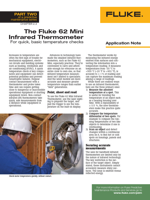
The Fluke 62 Mini Infrared ThermometerFor quick, basic temperature checksAdvances in technology have made the smallest infrared ther-mometers, such as the Fluke 62 Mini, especially practical. They’re convenient to carry and afford-able enough for everyone on an entire crew to own one, so that infrared temperature measure-ment isn’t limited to specialists. And the latest models are more accurate and measure greater temperature ranges than earlier “mini” generations.Point, shoot and readTo use the Fluke 62 Mini Infrared Thermometer, use the laser sight-ing to pinpoint the target, and pull the trigger to see the tem-perature on the built-in display.Increases in temperature are often the first sign of trouble for mechanical equipment, electri-cal circuits and building systems such as heating, ventilation and air conditioning (HVAC). A quick temperature check of key compo-nents and equipment can detect potential problems and prevent catastrophic failures. Regular contact measurement with a thermometer and probe takes time and can require gettingclose to dangerous or inaccessible operational equipment or shutting equipment down. Non-contact infrared (IR) thermometers take quick, safe measurements from a distance while equipment is operational.Application NoteFor more information on Fluke Predictive PART TWOof a predictive maintenance seriesCheck motor temperatures quickly, without contact.The thermometer works by measuring the infrared energy emitted from surfaces and con-verting the information into a temperature reading. It measures temperatures from -30 °C to +500 °C (-20 °F to +932 °F), is accurate to ± 1% of reading and can capture the maximum reading among a range of readings.While there are endless ways to use an infrared thermometer, here are the three primary ones:1) M easure the absolutetemperature at a spot. This is useful for trending thetemperature of an object such as a bearing housing over time. With a repeatability of ± 0.5 %, the new thermom-eters make this practice quite accurate.2) C ompare the temperature differential of two spots. For example to compare the run-ning temperatures of two like objects to determine if one is overheating.3) S can an object and detect changes within a continuous area on it, to find hot or cold spots on housings, panels and structures.Securing accurate measurementsThe uses for handheld infrared thermometers are limited only by the nature of infrared technology. The key restriction is the sur-face of the target object. Simply stated, these instruments cannot accurately measure shiny sur-faces. The issue is emitted versusreflected energy.CHAPTER 2.3EmissivityOf the kinds of energy—reflected, transmitted and emitted—emanat-ing from an object, only emitted infrared energy indicates the object’s surface temperature. Transmitted and reflected energy do not. When IR thermometers measure surface temperatures, they sense all three kinds of en-ergy. Therefore, they have to be adjusted to read emitted energy only. The Fluke 62 Mini Infrared Thermometer has a fixed, pre-set emissivity of 0.95, which is the emissivity value for most organic materials as well as painted or oxidized surfaces.To accurately measure the surface temperature of a shinyobject, cover the target surfacewith masking tape or flat blackpaint and allow enough timefor the tape or paint to reachthe temperature of the material underneath.Distance-to-spot ratioThe optical system of an infrared thermometer collects the infrared energy from a circular area or spot and focuses it on the detec-tor. The farther a target is fromcreated on the target will be. Optical resolution is defined by the ratio of the distance from theglass and, as noted, will be inac-curate if used to measure shiny or polished metal surfaces (stainless steel, aluminum, etc.).Users of IR thermometers also must be alert to environmen-tal conditions. Steam, dust and smoke, for example, can prevent accurate temperature readings by obstructing a unit’s optics. A dirty lens can also affect read-ings. Lenses should be cleaned with dry, clean plant air or a fluid made specifically for cleaning lenses. Also, changes in ambi-ent temperature can influence a thermometer’s performance. If an IR unit is exposed to abrupt temperature changes of 11 °C (20 °F) or more, the user should allow at least 20 minutes for the unit to adjust to the new ambienttemperature.instrument to the object com-pared to the size of the spot (“dis-tance-to-spot” or D:S ratio). For the Fluke 62 Mini the distance-to-spot ratio is 10:1. This means that at a distance of 10 inches the spot is about one inch in diam-eter. The larger its ratio number the better is the instrument’s resolution. Resolution is important becauseit relates directly to getting good readings by ensuring that the target is larger than the spot size. The smaller the target, the closer one must be to it. When accuracy is critical, the target should be at least twice as large as the spot. Other factors to consider These instruments measure only surface temperatures, not internal temperatures. Furthermore, they cannot take readings throughEven considering the limitations of infrared temperature moni-toring, there are still so many possible uses for this technology that trying to list them all would be fruitless. Here are some of the most common and particularly successful applications. Predictive maintenance Regular maintenance in industrial and institutional locations keeps motors, pumps and gearboxes from experiencing catastrophic failures that can halt production or pose safety problems. In an infrared maintenance program, technicians set up an inspection route and measurement param-eters for each piece of key equip-ment and/or component. Then, they take an infrared temperature measurement on a regular basis, record the measurement, and compare against previous read-ings for any changes.As an example, a technician can use a Fluke 62 Mini to check the operation of an induction motor on a critical piece of equip-ment. She or he would start by reading the unit’s specifications on the plate attached to it. The plate will reveal either a Temper-ature Rise Rating or a Motor Class Rating for the motor. The rise rat-ing gives the maximum allowable operating temperature above am-bient. The motor class rating, e.g. “Class A,” will reveal an absolute maximum operating temperature. Both pertain to internal-winding temperatures. Of course, a contact thermometer cannot measure these temperatures while the motor is running. However, an operator or technician can use a non-contact IR thermometer to measure the temperature of the motor case. She or he should add 10 °C (18 °F) to surface scans to determine the internal operating temperature. For each 10 °C (18 °F) above the maximum operating temperature, the life of the motor is likely to decrease by 50%.If the motor is extremely hot it could be a fire hazard.Using infrared thermometryfor plant maintenance reducesrepair costs and avoids equip-ment stoppages. Industrialmaintenance personnel, buildingmanagers, HVAC technicians andeven homeowners can reducecosts by repairing only whatneeds to be fixed. They can avoidunplanned equipment stoppagesby making specific, necessaryrepairs before equipment fails.Then, after repairs, they can per-form new temperature measure-ments on the same equipment todetermine whether the repairswere successful.Electrical inspectionsElectrical systems supply essen-tial power to every industrial,commercial and residential set-ting. With degradation over timeand the general vulnerability ofelectrical connections, it’s impor-tant to monitor electrical sys-tems for loose, dirty or corrodedconnections, flaws in transformerwindings, hot spots in panelboxes and other telltale signs oftrouble.The Fluke 62 Mini can beinvaluable for finding developinghotspots in electrical equipmentthat may indicate a short circuit,a fused switch or an overload. Ingeneral, higher operating temper-atures reduce the life of electricalcomponents by damaging insula-tion and raising the resistance ofconductor materials. Pinpointedby a non-contact IR thermometer,these situations signal that actionis required.Measure moving targets easily.Use unit in close range fornear-distance targets.HVAC inspectionsHeating and cooling systems, whether for maintaining pro-duction parameters or human comfort, are easily monitored with the Fluke 62 Mini Infrared Thermometer. Check air stratifica-tion, supply and return registers, furnace performance and steam distribution systems and conduct energy audits to pinpoint system upgrade opportunities.For example, IR non-contact thermometers can be used to troubleshoot steam traps, which are designed to remove water (condensate) that has condensed from the steam as it travels in transfer pipes. If a steam trap fails while open, it will leak steam, causing an energy loss. If it fails while closed, it won’t remove condensate from the steam line, making it useless. A faulty steam trap can cost a plant $500 USD or more per year, and in any given year, 10 % of all industrial steam traps fail. Since many plants have as many as 1,000 traps, they can quickly become high-value main-tenance targets.To verify whether a steam trap is working properly, use a non-contact thermometer like the 62 Mini to measure from input to output. On a properly operating trap, the temperature should drop significantly. If the temperature doesn’t drop, the steam trap has failed open and is passing super-heated steam into the condensate line. If the temperature drop is overly large, the trap may be stuck closed and is not ejecting heated condensate. Condensate in steam lines reduces the effec-tive energy of the steam and can cause difficulties in steam drivenprocesses.Use non-contact temperature measurements for inaccessible targets.Fluke.Keeping your worldup and running.Fluke CorporationPO Box 9090Everett, WA USA 98206Fluke Europe B.V.PO Box 1186, 5602 BDEindhoven, The NetherlandsFor more information call:U.S.A. (800) 443-5853 orFax (425) 446-5116Europe/M-East/Africa (31 40) 2 675 200 orFax (31 40) 2 675 222Canada (800) 36-FLUKE orFax (905) 890-6866Other countries (425) 446-5500 orFax (425) 446-5116Web access: ©2005 Fluke Corporation. All rights reserved.Printed in U.S.A. 6/2005 2517382 A-EN-N Rev A。
fluke绝缘电阻测量仪说明书

fluke绝缘电阻测量仪说明书交流传动系统调试时,必须使用绝缘电阻测试仪对变频器和电动机的主回路和控制回路分别进行绝缘测试,从而保证系统的安全运行。
福禄克Fluke1587绝缘电阻测试仪不仅对主回路进行快速测量,而且还能提供‘电阻档’功能对控制回路进行绝缘测试。
使用福禄克Fluke1587绝缘电阻测试仪进行变频器主回路(以VACONNXP产品为例)绝缘测量应遵循下列步骤:1.断开变频器所有与外界的接线,确保被测电路未连接任何电源。
然后将输入端L1,L2,L3和输出端U,V,W短接在一起2.将福禄克绝缘电阻测试仪的测试探头插入‘+,输入端子,然后将’另一端接到‘接地点’3.将探头与待测电路连接,绝缘电阻测试仪会自动检测电路是否通电。
如果电路中的电压超过30Vacordcjlj试被自动禁止。
4.选择福禄克Fluke1587绝缘电阻测试仪的‘Insulationtest’测试功能。
5.通过‘Range’按钮选择合适的测试电压(500Vdc)。
6.按住‘Insulationtest’测试键,读出绝缘电阻测试仪上所显示的阻抗值。
读数达到稳定可能需要几秒钟。
阻抗值越髙越好,此时读数为550兆欧,可以判断该绝缘良好。
7.继续将绝缘电阻测试仪的探头留在测试点上,然后释放‘Insulationtest’按钮。
被测电路即开始通过仪表放电,直至结束。
变频器控制回路(以VACONNXP产品为例)绝缘测量时应该注意的是必须用福禄克Fluke1587绝缘电阻测试仪带的‘电阻档’进行连续性测试,一般测试值>=1兆欧,表示绝缘良好。
使用绝缘电阻测试仪进行电动机绝缘测试时,应相对于接地线,分别测试U,V,W三相绕组线,一般测量值>=5兆欧,表示绝缘良好。
Fluke Corporation 电压 连续性测试仪 T50 用户手册说明书

®Model T50Voltage/ContinuityTester Manual de instruccionesPN 2438510May 2005© 2005 Fluke Corporation. All rights reserved.Printed in China.Advertencias indicadas en el instrumento o en el manual de instrucciones:Atención! Advertencia:sitio peligroso.Observe el manual de instrucciones Advertencia! Importante.Tener en cu-enta.Cuidado! Peligro de tensión.Peligro de descarga eléctricaAislación doble o reforzada completa según clase II IEC 61140.hasta 690 V .Sello de conformidad CE, certifica el cumpli-miento de las normas vigentes.Se cumple el lineamiento EMV (89/336/EWG) i T am-bién cumple las normas de baja tensión (73/23/EWG).El manual de instrucciones contiene informaciones y advertencias necesa-rias para una correcta y segura utiliza-ción del instrumento.Antes de la utili-zación (puesta en marcha / montaje)del instrumento se debe leer atenta-mente el manual de instrucciones y cumplirlo en todos sus puntos.Si no se atienden las instrucciones o si se omite prestar atención a las adver-tencias y observaciones, se pueden producir lesiones graves al usuario o daños al instrumento.Generalidades / Volumen de entregaLa línea FLUKE T50 está comprendida por una serie de tester de voltaje y continui-dad.Los voltímetros son de extrema ayuda tanto en el área industrial como para el técnico electricista y el electrónico amateur Fluke T502cuando se trata de realización mediciones usuales.Estos modelos están provistos de las sigu-ientes funciones:• Construido de acuerdo la las normas DIN EN 61243-3, DIN VDE 0682 sección 401(anteriormente DIN VDE 0680 sección 5),IEC 61010• Visor LED• Medición de tensión alterna y continua hasta 690V• T est monopolar de las fases• T est de continuidad y de diodosConstatar al desembalar el instrumento si éste se encuentra en perfectas condicio-nes.El volumen de entrega consiste de:1 voltímetro FLUKE T502 baterías 1,5V IEC LR031 manual de instruccionesIndicaciones de seguridadLos instrumentos FLUKE T50 fueron con-struidos y probados de acuerdo a las nor-mas para voltímetros DIN EN 61243-3,DIN VDE 0682 sección 401 (anteriormente DIN VDE 0680 sección 5), EN 61010 y IEC 61010.Estos han dejado nuestra planta en perfecto estado.Para mantener este esta-do el usuario debe de observar las indica-ciones de seguridad contenidas en este manual.Para evitar un golpe eléctrico, deben cumplirse las disposiciones de seguri-dad y VDE sobre tensiones de con-tacto excesivas, cuando se trabajen con tensiones mayores de 75V (60V)CC ó 50V (25V) ef CA.Los valores entre paréntesis rigen para ámbitos circunscriptos (como p.ej.medicina,agricultura)Fluke T50Indicaciones de seguridad3Antes de realizar una medición asegu-rarse que las líneas de medición asícomo el instrumento se encuentren en perfecto estado.Las puntas de prueba sólo se deben sostener por las superficies previstas para ello.Siempre se debe evitar el con-tacto directo con las puntas de prueba.El instrumento sólo debe ser utilizado dentro de los rangos especificados y en instalaciones de baja tensión de hasta 690 V .Antes de cada uso debe asegurarse que el instrumento funcione perfecta-mente (p.ej.en una fuente de tensión conocida)Los voltímetros no deben ser más utili-zados si una o más funciones están fuera de uso o si no se puede recono-cer que el instrumento está en condi-ciones de ser utilizado.No está permitido el realizar mediciones en condiciones ambientales húmedas.Una visualización correcta solamente es posible dentro de una temperatura de – 10°C a + 55°C y una humedad re-lativa ambiente de menos de 85%.Si ya no está garantizada la seguridad del operador, el instrumento debe po-nerse fuera de funcionamiento y ase-gurarse contra uso involuntario o inde-bido.Este es el caso cuando el instrumento:• presenta daños evidentes• ya no realiza las mediciones deseadas •fue almacenado un tiempo excesivo en condiciones adversas• estuvo expuesto a exigencias mecánicas durante el transporteEn todos los trabajos deben cumplirse las normas de prevención de acciden-tes de las asociaciones profesionales que se encuentren vigentes para insta-laciones eléctricas y equipos.Fluke T50Indicaciones de seguridad4Utilización de acuerdo a su funciónEl instrumento sólo debe ser utilizado bajo las condiciones y con el fin para el cual éste fue construido.Para ello debe de ob-servarse las advertencias de seguridad,los datos técnicos con las condiciones am-bientales y la utilización en un ambiente seco.La seguridad en la operación no se podrá garantizar si el usuario realiza modificaciones o cambios en la con-strucción.Si fuera necesario abrir el instrumento,p.ej.para cambiar los fusibles, esto sólo deberá ser realizado por un técni-co.Antes de abrir el instrumento, éste debe ser apagado y desconectado de todo circuito de corriente.ElementosPunta de prueba de mano – (L1)Punta de prueba del instrumento +(L2)LEDs para la visualización de tensión LED para indicación monopolar de las fases LED para continuidad Indicador de polaridad Compartimiento para las bateríasFluke T50Manual de instrucciones5Realización de mediciones Preparación de seguridadPara cada test deben de observarse las advertencias de seguridad mencio-nadas.Antes de cada utilización debe realizarse primeramente un test para constatar que el instrumento funcione debidamente.Prueba de funcionamiento:• Unir una punta de prueba con la otra • Se escuchará un sonido y el LED Rx/Ωse iluminaráLa indicación de tensión del FLUKET50 funciona también aunque las ba-terías estén agotadas o sin baterías.Los voltímetros no deben ser más utili-zados si una o más funciones están fuera de uso o si no se puede recono-cer que el instrumento está en condi-ciones de ser utilizado.Los instrumentos FLUKE T50 poseen una carga integrada que posibilita el disparo de un diferencial de 10 mA o 30 mA.En el caso de pruebas de tensión (L con PE) en instalaciones con disyuntor diferencial puede dispararse el mismo.Para evitarlo, debe realizarse primero el test entre L y N (aproximadamente 5segundos).A continuación se puede probar L con PE sin disparar el diferen-cial.Medición de tensiónObserve las medidas de seguridad in-dicadas.•Unir ambas puntas de prueba con el ob-jeto a medir.Fluke T50Manual de instrucciones6A partir de una tensión > 12 V el voltí-metro entra en funcionamiento auto-máticamente.•Visualización de la tensión por LEDs (3) •En el caso de trabajarse con tensión al-terna, se iluminarán los LEDs con los símbolos "+”y "-" y adicionalmente se escuchará una señal.•En caso de tensión DC el LED (6) destel-la y se escucha una senal.•Los instrumentos poseen una cadena de LEDs con los valores 12V, 24V, 50V, 120V, 230V, 400V y 690V.•En el caso de trabajarse con tensión continua, la polaridad de la tensión indi-cada se refiere a la punta de prueba (+).•Por razones técnicas el instrumento no se encenderá con tensión continua en el rango de aprox.0V hasta –3V. Indicación monopolar de las fasesLa determinación unipolar de fasesfunciona a partir de una tensión alter-na de aprox.100 V (polaridad > 100VCA).En el caso de realizar un test de lasfases para determinar un conductorexterno es posible que la función delvisor bajo determinadas condiciones(como p.ej.cuando hay protectoresaislantes o en lugares aislados) seaperjudicada.El test unipolar de fases no es el medio adecuado para determinar la presen-cia de tensión.Para ello es necesario un test bipolar de voltaje.•Conectar las puntas de prueba con el objeto a medir•Una señal acústica indicará la fase y en el visor se iluminará el LED (4)Fluke T50Manual de instrucciones7Medición de tensión con dis-paro de diferencialEn caso de realizar un test de voltaje en ins-talación que poseen un disyuntor diferencial con 10 mA o 30 mA de corriente nominal de fuga, éste puede ser disparado.Para ello se debe medir la tensión entre L y PEentre L y N por aproximadamente 5 se-gundos.A continuación se puede pro-bar L con PE sin disparar el diferencial. Test de continuidadAntes de probar todo diode debe de asegurarse que el diodo a probar no esté bajo tensió polaridad de la tensión de prueba en la punta de prue-ba de mano es positiva (+).•Probar en forma bipolar la existencia de tensión en el objeto a medir.• Conectar ambas puntas de prueba con el objeto a medir.Si existe continuidad se escuchará una señal y el LED con la indicación conti-nuidad Rx/Ω(5) se iluminará. MantenimientoUtilizado de acuerdo al manual de instruc-ciones, el instrumento no requiere ningún mantenimiento especial.Si a pesar de ello surgiera algún desperfecto en la función, nuestro servicio técnico se ocupará de controlar el instrumento.Fluke T50Manual de instrucciones8LimpiezaSi el instrumento se llegara a ensuciar por el uso cotidiano, se lo podrá limpiar con un paño húmedo y algo de detergente suave.Antes de comenzar con la limpieza, cerció-rese que el instrumento esté desconecta-do del suministro externo de tensión y de los demás instrumentos conectados.Nunca utilice productos agresivos o sol-ventes para la limpieza.Una vez limpiado,el instrumento no debe ser utilizado por aproximadamente 5 horas.Intervalo de calibraciónPara conservar la precisión de los resulta-dos de medición indicada, el instrumento debe ser calibrado periódicamente por nuestro servicio técnico.Recomendamos un intervalo de calibración de un año.Reemplazo de bateríasSi al unir las puntas de prueba no suena una señal deben cambiarse las baterías.•Antes de cambiar una batería se debe separar el voltímetro FLUKE T50 de todo circuito a medir.•Abrir el compartimiento de las baterías girándolo (p.ej.con una moneda) en el sentido indicado con la flecha.•Quitar las baterías agotadas.Fluke T50Manual de instrucciones9Por favor, piense también en nuestro medio ambiente.No tire las baterías usa-das a la basura doméstica normal, sino entréguelas a los depósitos o colectores de basura especiales.Deberán observarse las respectivas disposiciones en vigor sobre la recogi-da, el aprovechamiento y la eliminaci-ón de baterías y acumuladores usa-dos.Datos técnicosRango de tensión12...690V CA/CC Resolución LED ±12, 24, 50, 120, 230, 400,690 VTolerancia DIN VDE 0682, sección 401Determinación de tensión automáticaSeñal acústica (tensión AC) siDeterminación de polaridad para todos los rangos Determinación de rangoautomáticaTiempo de reacción <0,1 s LEDRango de frecuencia DC, 0...65 HzCarga automática (disy.dif.) siCarga interna aprox.2,1W para 690V Corriente de prueba < 3,5 mACorriente pico Is = 0.2 ATiempo de encendido ED (DT) = 30 sTiempo de recreo:240sAuto Power On > 12 V CA/CCDeterminación unipolar de fasesRango de tensión 100...690 V CAFrecuencia 50...65 HzPrueba de continuidadRango de resistencia 0...200 k ΩPrecisión RN + 50%Corriente de prueba 3 µAProteción de sobretensión 690V CA/CCSuministro de energía 2 de 1,5V Micro IEC LR03Toma de corriente max.30mA / aprox.250 mW Temperatura -10°C...55°CHumedad max.85% humedad relativaambienteAltura sobre el nivel del mar:hasta 2000 m Categoría de sobretensión:CAT III / 600V Grado de polución:2Protección IP54De acuerdo a:DIN EN 61243-3, DIN VDE 0682 partie 401 (DIN VDE 0680Partie 5, EN 61010, EN 61010,IEC 61010)Peso:130g (incl.Baterías)Dimensiones:210 x 40 x 22 mm Fluke T50Datos técnicos10Garantía limitada y limitación de responsabilidad Se garantiza que este producto de Fluke no tendrádefectos en los materiales ni en la mano de obra durante un año a partir de la fecha de adquisición.Esta garantía no incluye fusibles, baterías desechab-les ni daños por accidente, maltrato, uso indebido,alteración, contaminación o condiciones anormales de funcionamiento o manipulación.Los revendedores no están autorizados para otorgar ninguna otra garantía en nombre de Fluke.Para obtener servicio degarantía, póngase en contacto con el centro de servi-cio autorizado por Fluke más cercano para obtener la información correspondiente de autorización de la devolución, y luego envíe el producto a dicho centro de servicio con una descripción del problema.ESTA GARANTÍA ES SU ÚNICO RECURSO.NO SE CONCEDE NINGUNA OTRA GARANTÍA, EXPRESA O IMPLÍCITA, T AL COMO AQUELLA DE IDONEIDAD PARA UN PROPÓSITO DETERMINADO.FLUKE NO SE RESPONSABILIZA DE PÉRDIDAS NI DAÑOS ESPECIALES, MEDIATOS, INCIDENTALES O INDI-RECTOS, EMERGENTES DE CUALQUIER CAUSA O TEORÍA.Dado que algunos países o estados no permiten la exclusión o limitación de una garantía implícita, ni de daños incidentales o indirectos, es posible que las limitaciones de esta garantía no sean de aplicación a todos los compradores.Fluke T50Garantía11Fluke CorporationP .O.Box 9090Everett WA98206-9090Fluke Europe B.V .P .O.Box 11865602 B.D.Eindhoven NetherlandsFluke T50 12。
fluke万用表使用说明书
fluke万用表使用说明书中FLUKE 15B型和FLUKE 17B可以测量电压、电阻、电流、二极管、三极管、MOS场效应管的测量等几大功能综合在一起的强大的一款小仪器。
为了让你更好的掌握万用表测量方法,电工之家来详解一下它的使用方法和功能与注意事项。
一、测量电压时测量直流电压时,如电池、随身听电源等。
首先将黑表笔插进相印的孔,把旋钮选到相印位置。
二、测量交流电压的时表笔插孔与直流电压的测量一样,不过应该将旋钮打到交流档处所需的量程即可。
交流电压无正负之分,测量方法跟前面相同。
无论测交流还是直流电压,要注意自身安全,不要随便用手触摸表笔的金属部分。
三、测量电流时测量直流电流时。
将黑表笔插入对应孔。
将FLUKE 15B型和FLUKE 17B万用表串进电路中,保持稳定,即可读数。
四、测量电阻时用表笔接在电阻两端金属部位,测量中可以用手接触电阻,但不要把手同时接触电阻两端,这样会影响测量精确度,因为人体是电阻很大。
五、测量二极管时表笔位置与电压测量一样;用红表笔接二极管的正极,黑表笔接负极,这时会显示二极管OL。
再次对调表笔会显示一个数值。
再次调换表笔,显示屏显示“OL.”则为正常。
因为二极管的反向电阻很大,否则此管已被击穿或性能已经改变。
六、三极管的测量表笔插位同上;其原理同二极管。
先假定A脚为基极,用黑表笔与该脚相接,红表笔与其他两脚分别接触其他两脚;然后再用红笔接A脚,黑笔接触其他两脚,且此管为PNP管。
那么集电极和发射极如何判断呢?数字表不能像指针表那样利用指针摆幅来判断。
七、MOS场效应管的测量利用FLUKE 15B型和FLUKE 17B的二极管档。
若某脚与其他两脚间的正反压降均大于2V,即显示“1”,此脚即为栅极G。
再交换表笔测量其余两脚,压降小的那次中,黑表笔接的是D极(漏极),红表笔接的是S极(源极)。
在使用FLUKE 15B型和FLUKE 17B 的同时也要注意以下问题避免可能受到电击或人员伤害,以及避免对电表或待测装置造成损害,请遵照下面的惯例说明使用电表:①进行连接时,先连接公共测试导线,再连接带电的测试导线;切断连接时,则先断开带电的测试导线,再断开公共测试导线。
福禄克说明书

3.00 kΩ至29.99 kΩ
30.0 kΩ至299.9 kΩ
分辨率
0.001Ω
0.01Ω
0.1Ω
1Ω
10Ω
100Ω
精度
±(读数的2 % + 2位数)
操作误差
±(读数的5 % + 5位数)
测量时间
通常为6秒
最大干扰电压
24 V,超过24 V无法启动测量
最大过载
Urms最大= 250 V
重量
≤ 1.1 kg (2.43 lb)(不含附件);7.6 kg (16.8 lb)(携带箱中含附件和电池)
外壳材料
聚酯
直流和交流干扰电压的测量(UST)
测量误差极限:方法
全波整流
测量范围
1 V至50 V
显示范围
0.0 V至50 V
分辨率
0.1 V
频率范围
交流/直流45 Hz至400 Hz正弦波
精度
采用无桩测试时,无需断开接地棒-保持结合的接地系统在测试中的完整性即可。如今无需再花费时间为系统上的接地棒放置和连接地桩,这能够节约大量的时间。在一些您之前从未考虑过的位置,您也可以执行接地测试,包括建筑物内部、电缆塔或任何您无法接触到土地的位置。
最全面的测试仪
Fluke 1625-2是一款与众不同的接地测试仪,可以完成所有四种类型的接地测量:
RH和R的测量误差S
通常为RETOTAL+ RS+ R的10 %H
测量时间
固定频率时通常为8秒使用自动频率控制,最大30秒,完成所有测量频率循环。
待测单个支路的最小电流
0.5 mA
使用互感器(1000:1)
0.1 mA
fluke中文使用手册805彩图

快速参考指南
测量提示
指示灯状态 符合 ISO 10816-1 的振动烈度
机器 in/s
90˚
0.01 0.02 0.03 0.04
数据传输
LCD 显示屏
红外测温 传感器
绿灯亮 绿灯灭 将传感器尖端放到测试表面 上,尽量靠近轴承。 施加压 力,直到绿灯熄灭。
绿灯灭 数据测量完成。
红灯亮 出错。用力或持续 时间不足,无测量 数据。
1.10 1.77
测振仪运用一种专属的算法:Crest Factor + (CF+)。 为了方便用户理解,CF+ 的 烈度等级在 1 到 16 之间取值。 CF+ 值越高,说明轴承受损程度越大。 每次测量获得的 CF+ 值显示在测振仪显示屏的轴承字段。 按 和 可在 CF+ 值和 以加速度为单位的高频振动级别之间切换。
使用前必读
导航
一般性操作: 面底部提供了关于
在菜单选项间移动光 标或编辑菜单选项 调用上一个菜单 打开下一个菜单或设 定选项 为测振仪保存新的选 项设置
测振仪配置
“设置”菜单
测量
快速测量 自动保存测量值
每个菜单都在界 其内容的导航提示。
单位
为防止红外测温仪导致人身伤害: ●● 有关实际温度,请参阅发射率信息。 反光物体会导致测得的温度比实际温度要低。 这些物体会 产生烧伤危险。 ●● 请勿在高温且无人照看的情形下使用产品。 为防止靠近转动设备而导致人身伤害: ●● 在转动设备周围要小心。 ●● 让绳索和带子隐藏起来。
fluke使用说明书
福禄克FLUKE DTX系列(Dtx-1800,Dtx-1200,Dtx-lt)简单操作步骤说明:一、福禄克测试仪初始化步骤:1、充电:产品主机、辅机分别用电源适配器充电,直至电池显示灯转为绿色;2、设置语言:操作:将fluke dtx系列产品主机旋钮转至“SET UP”档位,按右下角绿色按钮开机;使用↓箭头;选中第三条“Instrument setting ”(本机设置)按“ENTER”进入参数设置,首先使用→箭头,按一下;进入第二个页面,↓箭头选择最后一项Language按“ENTER”进入; ↓箭头选择最后一项Chinese 按“ENTER”选择。
将语言选择成中文后才进行以下操作。
3、自校准:取fluke dtx系列产品Cat 6A/Class EA 永久链路适配器,装在主机上,辅机装上Cat 6A/Class EA 通道适配器。
然后将永久链路适配器末端插在Cat 6A/Class EA 通道适配器上;打开辅机电源,辅机自检后,“PASS”灯亮后熄灭,显示辅机正常。
“SPECIAL FUNCTIONS”档位,打开主机电源,显示主机、辅机软件、硬件和测试标准的版本(辅机信息只有当辅机开机并和主机连接时才显示),自测后显示操作界面,选择第一项“设置基准”后(如选错用“EXIT”退出重复),按“ENTER”键和“TEST”键开始自校准,显示“设置基准已完成”说明自校准成功完成。
二、设置福禄克测试仪基本参数操作:将fluke dtx系列产品主机旋钮转至“SET UP”档位,使用“↑↓”来选择第三条“仪器值设置”,按“ENTER”进入参数设置,可以按“←→”翻页,用“↑↓”选择你所需设置的参数,按ENTER 进入参数修改,用“↑↓”选择你所需采用的参数设置,选好后按ENTER选定并完成参数设置。
1、新机第一次使用需要设置的参数,以后不需更改。
(将旋钮转至“SET UP”档位,使用↓箭头;选中第三条:仪器设置值按ENTER进入如果返回上一级请按EXIT):1)线缆标识码来源:(一般使用自动递增,会使电缆标识的最后一个字符在每一次保存测试时递增一般不用更改)2)图形数据存储:(是)(否)通常情况下选择(是)3)当前文件夹:DEFAULT 可以按ENTER进入修改其名称(你想要的名字)4)结果存放位置:(使用默认值“内部存储器”假如有内存卡的话也可以选择“内存卡”)5)按→进入第2个设置页面,操作员:You Name 按ENTER 进入按F3删除原来的字符“←→↑↓”来选择你要的字符选好后按ENTER确定6)地点:Client Name,是你所测试的地点可以依照地e)小点进行修改7)公司:You Company Name,你公司的名字8)语言:Language,默认是英文9)日期:输入现在日期10)时间:输入现在时间11)长度单位:通常情况下选择米(m)2、新机不需设置采用原机器默认值的参数:1)电源关闭超时:默认30分钟2)背光超时:默认1分钟3)可听音:默认是4)电源线频率:默认50Hz5)数字格式:默认是6)将旋钮转至“SET UP”档位选择双绞线按ENTER 进入后NVP 不用修改7)光纤里面的设置,在测试双绞线是不须修改3、使用过程中经常需要改动的参数:将旋钮转至“SET UP”档位,选择双绞线,按ENTER进入:线缆类型:按ENTER进入后按↑↓选择你要测试的线缆类型例如我要测试超5类的双绞线在按ENTER进入后选择UTP 按ENTER ↑↓选择“Cat 5e UTP ” 按ENTER 返回。
福禄克Fluke dsp-40004300网络测试仪使用操作说明
操作:将旋钮转至“SET UP”档位,在第一个黑块处按“ENTER”进入测试标准和电缆类型选择,常用的是“TIA CAT 5E CHANNEL”(超五类通道标准,使用通道适配器);“TIA CAT 6 CHANNEL”(六类通道标准,使用通道适配器),“TIA CAT 6 PERM LINK”(六类永久链路测试标准,使用永久链路适配器),其他不常用,用“↑↓”和“PAGE UP (3号按键)、PAGE DOWN(4号按键)”选择你所需的标准,按“ENTER”确认,回到主菜单。
福禄克Fluke dsp-4000/4300网络测试仪使用操作说明
Fluke DSP4000/4300产品操作,福禄克DSP系列产品说明,操作步骤 一、福禄克DSP系列产品使用步骤: 1、充电: 将福禄克DSP系列产品主机、辅机分别用变压器充电,直至电池显示灯转为绿色; 2、自校准: 取校准模块(上有DSP4000 CAL MODULE字样),用校准模块将主
6.“AUDIBLE TONE”(声音提示):默认是Enable(是),一般不做改动。
7.“DATE”(日期):需要输入现在日期。
8.“DATE FORMAT”(日期格式):默认是日/月/年,一般不做改动。
9.“TIME”(时间):输入当时时间。
10.“TIME FORMAT”(时间格式):默认是 时/分/秒,一般不做改动。
8.“HEADROOM”:默认值是NEXT。
9.“CONFIGURE CUSTOM TEST”(配置订制的测试):自己设定测试标准,一般不用。
③.使用过程中经常需要改动的参数:
1.“TEST STANDARD, CABLE TYPE”(测试标准电缆类型):常用的是“TIA Cat 5E Channel”(超五类通道标准,使用通道适配器);“TIA Cat 6 Channel”(六类通道标准,使用通道适配器),“TIA Cat 6 Perm Link”(六类永久链路测试标准,使用永久链路适配器),其他不常用。或用“↑↓”和“Page UP (3号按键)、Page Down(4号按键)”选择你所需的其它标准,按“ENTER”确认,回到主菜单。
FLUKE 7-600 电能测试仪 说明书

7-600电能测试仪使用说明书P请先阅读:安全说明要确保安全使用测试仪,请遵循以下的说明:·如果测试仪或测试导线看起来已损坏,或者怀疑测试仪的运作不正常,请勿使用测试仪。
·先断开带电的测试导线,再断开公共测试导线。
·使用测试探针时,手指应保持在探针的保护装置的后面。
·请勿使用测试仪来测量会被测试仪的低输入阻抗(@2 千欧 (k W))损坏的电路的电压。
·切断、焊开、或断开电路前,应先切断通往被测电路的电源。
小量电流有危险性。
·不要在 7-600 测试仪端子和地线间施加超出 600 V均方根电压。
·在超出 60 V直流电压或 30 V交流电压均方根时使用电表,请特别留意。
该类电压有导致电击的危险。
PN 2063524 December 2002 (Simplified Chinese)ã2002 Fluke Corporation. All rights reserved. Printed in China.自动选择测试仪会自动选择正确的测量模式及量程。
在启动期间,测试仪会在“电阻/连通性”模式中开启。
如果输入端子间有大约 4.5 V以上的直流电压或交流电压,测试仪便会切换至直流电压或交流电压模式。
W警告在直流电压总线上的重复性瞬变,将使“自动选择”(Automatic Selection) (k) 选择交流电压,即使可能存在有危险的直流电压。
在直流电压及交流电压模式中,测试仪的输入阻抗很低(在@2 千欧 (k W)至 100 千欧 (k W) 之间)。
这个低阻抗会对叠加在被测 电路中,仅适用于测量阻抗电源电压。
不要使用测试仪来测量会被 2 千欧 (k W) 负荷损坏的电路的电压。
连通性电阻ah01i.eps直流电压及交流电压请参见“自动选择”部分。
直流电压 >4.5 V交流电压 >4.5 V均方根(VRMS)输入阻抗@2 千欧 (k W) 输入阻抗@2 千欧 (k W)ah02i.eps 待机模式如果测试仪已开启但超过 45 分钟不活动或未连接电压,显示屏会变成空白来保留电池寿命。
fluke中文使用手册1621

i
1621 用户手册
ii
表目录
表
1. 2. 3. 4.
标题
第页
可选附件............................................................................................ 4 特性和功能........................................................................................ 6 显示屏................................................................................................ 8 故障诊断............................................................................................ 14
开箱
在打开装运箱取出测试仪及其附件时,请参阅“附件”部分。请将包装 材料妥善保管供日后运输之需。 检查是否有缺件并仔细查看设备是否有如裂纹、凹痕或部件弯曲等损坏 现象。如果发现物品缺少或任何明显的机体损坏,请致电 Fluke 寻求协 助。请参阅“服务”部分获取 Fluke 的联系信息。
包装
运输测试仪时必须使用原始的包装材料。
特性和功能序号说明ahc2插孔用于连接辅助接地极bsp2插孔用于连接探针cec1插孔用于连接接地极dlcd显示屏见lcd显示屏e支架位于背面用于直立支撑测试仪f旋转开关用于选择测量功能极限模式和开机关机g皮套保护测试仪不受损坏h电池仓位于背面可容纳一节9v电池idisplay显示按钮用于选择测量结果和其它功能jstart开始按钮用于触发测量功能和其它功能6earthgroundtester特性软件要查看软件版本可将旋转开关设至off关闭位置然后按住start开始并将旋转开关设到任何on开启位置3pole2pole或limit
福禄克网络测线仪使用说明书
FLUKE网络测试仪器说明书班级:330910姓名:***学号:********一、福禄克测试仪初始化步骤:1、充电:将Fluke dtx系列产品主机、辅机分别用电源适配器充电,直至电池显示灯转为绿色;2、设置语言:操作:将fluke dtx系列产品主机旋钮转至“SET UP”档位,按右下角绿色按钮开机;使用↓箭头;选中第三条“Instrument setting ”(本机设置)按“ENTER”进入参数设置,首先使用→箭头,按一下;进入第二个页面,↓箭头选择最后一项Language按“ENTER”进入; ↓箭头选择最后一项Chinese 按“ENTER”选择。
将语言选择成中文后才进行以下操作。
3、自校准:取fluke dtx系列产品Cat 6A/Class EA 永久链路适配器,装在主机上,辅机装上Cat 6A/Class EA 通道适配器。
然后将永久链路适配器末端插在Cat 6A/Class EA 通道适配器上;打开辅机电源,辅机自检后,“PASS”灯亮后熄灭,显示辅机正常。
“SPECIAL FUNCTIONS”档位,打开主机电源,显示主机、辅机软件、硬件和测试标准的版本(辅机信息只有当辅机开机并和主机连接时才显示),自测后显示操作界面,选择第一项“设置基准”后(如选错用“EXIT”退出重复),按“ENTER”键和“TEST”键开始自校准,显示“设置基准已完成”说明自校准成功完成。
二、设置福禄克测试仪基本参数操作:将fluke dtx系列产品主机旋钮转至“SET UP”档位,使用“↑↓”来选择第三条“仪器值设置”,按“ENTER”进入参数设置,可以按“←→”翻页,用“↑↓”选择你所需设置的参数,按ENTER进入参数修改,用“↑↓”选择你所需采用的参数设置,选好后按ENTER选定并完成参数设置。
三、福禄克测试仪测试过程:⒈根据需求确定测试极限值和电缆类型:通道测试还是永久链路测试?是CAT5E还是CAT6还是其他?⒉关机后将测试标准对应的适配器安装在主机、辅机上,如选择“TIA CAT5E CHANNEL”通道测试标准时,主辅机安装“DTX-CHA002”通道适配器,如选择“TIA CAT6A PERM.LINK”永久链路测试标准时,主辅机各安装一个“DTX-PLA002”永久链路适配器。
FLUKE435电能质量测试仪使用手册
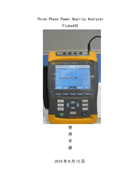
Three Phase Power Quality AnalyzerFluke435使用手册2010年8月12日Fluke整体介绍1测量范围:1。
1电压输入:a)最大输入电压:1000Vrmsb)标称电压范围:50至500V,内部分为三个范围:500V、250V、125Vc)最大峰值电压:6KVd)输入阻抗:4MΩ//5PF1.2 电流输入:a)输入范围:用仪表附带的电流夹i5s,1至5Arms;用可选电流夹i430flex—4pk,0。
1至3000 Armsb)输入阻抗:50KΩ1.1.2标称频率:40…70Hz1。
2菜单功能介绍:Fluke435菜单主要有SETUP、SCOPE、MENU、MONITOR、MEMORY、SAVE SCREEN1。
2.1对测试仪进行设置:使用设置(SETUP)功能1。
2。
2检查电压导线和电流线夹是否正确连接:使用示波器波形(Scope Waveform)和示波相量(Scope Phasor)功能1。
2。
3查看电力系统的各项数据:使用菜单(MENU)功能1.2.4对测试仪数据集进行内存管理:使用内存(MEMORY0)功能1.2。
5对电力系统电能质量有一个总体了解:使用检测(MONITOR)功能。
1。
2.6 制作屏幕画面:使用制作屏幕画面(SAVE SCREEN)功能2具体使用介绍:打开测试仪,会出现一个开机欢迎屏幕:按F1键可查看测试仪设置的系统接线方式示波器设置菜单记忆、存储检测屏幕画面确定2。
1设置测试仪:点击SETUP键,进入设置菜单界面我们按照设置菜单界面选项按从上到下的界面进行设置。
2.1.1 User用户参数选择:按F4键进入测用户参数选择菜单.a)相位标记(Phase Identification):使用下/下箭头键来选择A、B、C 或 L1、L2、L3.按功能键 F5 –确定(OK)来确认。
b)相位颜色(Phase Colors)使用功能键F1 至F4 来依照在美国、欧盟、英国使用或依照IEC 选择颜色.或者定义您自己的一个颜色组:使用上/下箭头键来选择一个相位,然后使用左/右箭头键来选择颜色.按功能键F5 –确定(OK)来确认。
Fluke 1535 1537 绝缘电阻测试仪 用户手册说明书

1535/1537绝缘电阻测试仪用户手册April 2017 Rev. 1, 6/21©2017-2021 Fluke Corporation. All rights reserved.Specifications are subject to change without notice.All Product names are trademarks of their respective companies.有限担保和有限责任Fluke 公司保证 Fluke 1537 自购买之日起,可享受三年材料及工艺的质保。
Fluke 公司保证 Fluke 1535 自购买之日起,可享受一年材料及工艺的质保。
本项保证不包括保险丝、可弃置的电池或者因意外、疏忽、误用或非正常情况下 的使用或处理而损坏的产品。
经销商无权以 Fluke 的名义提供其它任何保证。
若 要在保修期内获得保修服务,请与您最近的 Fluke 授权服务中心联系,以获取有 关产品退还的授权信息,并将产品及故障说明寄至该服务中心。
本项保证是您唯一可以获得的补偿。
除此以外,Fluke 不作其它任何明示或暗示 的保证,例如适用于某一特殊目的的保证。
对于任何特殊的、间接的、偶然的、 并发性的损害或各种损耗,FLUKE 概不负责。
由于某些州或国家不允许将暗示 保证或偶发或后续损失排除在外或加以限制,故上述的责任限制或许对您不适 用。
11/99Fluke Corporation P.O.Box 9090Everett, WA 98206-9090U.S.A.中国服务中心中国北京市海淀区花园路 4 号通恒大厦 1 楼 101 室邮政编码:100088热线电话:400 921 0835目录概述 (1)联系 Fluke (2)安全须知 (2)符号 (5)打开测试仪的包装 (6)测试仪 (7)按键 (7)测试仪打开/关闭 (9)屏幕 (10)屏蔽端子的使用 (11)测试电路连接 (13)进行绝缘测试之前 (14)预设测试电压选择 (15)步进设定测试电压(限1537) (15)选择步进或稳态测试(限1537) (16)设置限时测试(限1537) (16)计划指数(PI) (17)介质放电(DD - 限1537) (17)介质吸收率(DAR) (18)绝缘测试 (18)保存测试结果(限1537) (20)查看保存在内存中的测试结果(限1537) (21)删除保存在内存中的测试结果(限1537) (23)交流电压/直流电压/电阻(限1537) (23)1537 型 PC 软件 (24)维护 (25)清洁 (25)更换电池 (25)零件和附件 (26)一般技术指标 (28)电气技术指标 (28)测量和电阻原理 (32)i概述Fluke 1535/1537 Insulation Testers(以下简称“本测试仪”或“本产品”)是用于检验通用电路设施的高电压绝缘测试仪,例如开关设备、电动机、电缆等。
福禄克Fluke dsp-40004300网络测试仪使用操作说明
福禄克Fluke dsp-4000/4300网络测试仪使用操作说明Fluke DSP4000/4300产品操作,福禄克DSP系列产品说明,操作步骤一、福禄克DSP系列产品使用步骤:1、充电:将福禄克DSP系列产品主机、辅机分别用变压器充电,直至电池显示灯转为绿色;2、自校准:取校准模块(上有DSP4000 CAL MODULE字样),用校准模块将主Fluke DSP4000/4300产品操作,福禄克DSP系列产品说明,操作步骤一、福禄克DSP系列产品使用步骤:1、充电:将福禄克DSP系列产品主机、辅机分别用变压器充电,直至电池显示灯转为绿色;2、自校准:取校准模块(上有“DSP—4000 CAL MODULE”字样),用校准模块将主机及辅机连接好。
打开辅机电源,辅机自检后,“PASS”灯亮后熄灭,显示辅机正常。
将旋钮开关转到任何模式即可打开主机电源,显示主机、辅机软件、硬件和测试标准的版本(辅机信息只有当辅机开机并和主机连接时才显示),自测后显示操作界面,将旋扭转至“SPECIAL FUNCTIONS”档位,用“↑↓”箭头选择第七项“SELF CALIBRATION”后(如选错用“EXIT”退出重复),按“ENTER”键和“TEST”键开始自校准,显示“SELF CALIBRATION COMPLETE”说明自校准成功完成。
3、设置参数:操作:将旋钮转至“SET UP”档位,在第一个黑块处按“ENTER”进入测试标准和电缆类型选择,常用的是“TIA CA T 5E CHANNEL”(超五类通道标准,使用通道适配器);“TIA CAT 6 CHANNEL”(六类通道标准,使用通道适配器),“TIA CAT 6 PERM LINK”(六类永久链路测试标准,使用永久链路适配器),其他不常用,用“↑↓”和“PAGE UP (3号按键)、PAGE DOWN(4号按键)”选择你所需的标准,按“ENTER”确认,回到主菜单。
Fluke 435 操作说明书(图文演示)
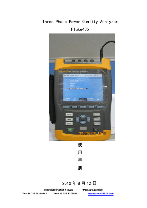
Three Phase Power Quality AnalyzerFluke435使用手册2010年8月12日Fluke整体介绍1测量范围:1.1电压输入:a)最大输入电压:1000Vrmsb)标称电压范围:50至500V,内部分为三个范围:500V、250V、125Vc)最大峰值电压:6KVd)输入阻抗:4MΩ//5PF1.2 电流输入:a)输入范围:用仪表附带的电流夹i5s,1至5Arms;用可选电流夹i430flex-4pk,0.1至3000 Armsb)输入阻抗:50KΩ1.1.2标称频率:40…70Hz1.2菜单功能介绍:Fluke435菜单主要有SETUP、SCOPE、MENU、MONITOR、MEMORY、SAVE SCREEN1.2.1对测试仪进行设置:使用设置(SETUP)功能1.2.2检查电压导线和电流线夹是否正确连接:使用示波器波形(ScopeWaveform)和示波相量(Scope Phasor)功能1.2.3查看电力系统的各项数据:使用菜单(MENU)功能1.2.4对测试仪数据集进行内存管理:使用内存(MEMORY0)功能1.2.5对电力系统电能质量有一个总体了解:使用检测(MONITOR)功能。
1.2.6 制作屏幕画面:使用制作屏幕画面(SAVE SCREEN)功能打开测试仪,会出现一个开机欢迎屏幕:按F1键可查看测试仪设置的系统接线方式2.1设置测试仪:点击SETUP键,进入设置菜单界面我们按照设置菜单界面选项按从上到下的界面进行设置。
2.1.1 User用户参数选择:按F4键进入测用户参数选择菜单。
a)相位标记(Phase Identification):使用下/下箭头键来选择A、B、C 或 L1、L2、L3。
按功能键 F5 –确定(OK)来确认。
b)相位颜色(Phase Colors)使用功能键F1 至F4 来依照在美国、欧盟、英国使用或依照IEC 选择颜色。
Fluke123说明书

FLUKEFluke 123Industrial ScopeMeter使用手册第一章 测试仪的使用本章的目的本章对测试仪进行分步介绍。
介绍内容并不包括测试仪的所有性能,而只是通过一些基本的例子来介绍如何使用手册,进行基本的操作。
给测试仪接能电源按图1-1中的步骤(分3步),在标准交流电源上给测试工具接通电源。
关于如何使用电池电源请参阅第2章。
测试仪按最后一次的设置开始运行。
图1-1:给测试仪接通电源将测试仪复位按照如下步骤,可将测试仪恢复到出厂时的设置状态:这时视屏图象如图1-2。
图1-2:复位后的视屏改变背衬光接通电源时,视屏处于高亮度显示状态。
在使用电池时(无外接电源),视屏可置于节能光亮显示状态,以便节省电池。
请注意节能显示功能可使电池使用时间延长1小时。
视屏判读视屏划分为三个区域:判读区,波形区和菜单区。
阅读如下部分时请参照图1-3。
图1-3:视屏各区域判读区(A):提供各种数据显示。
因为只有输入端口A被打开,所以您只能看到输入端口A中的显示。
波形区(B):显示输入端口A中的波形。
下面的线显示量程/格和电源指示(交流电或电池)。
因为只有输入端口A被打开,所以您只能看到输入端口A中的波形显示。
请注意当使用电池时,会通过电池指示显示出电池的电量情况:菜单区(C):显示可以通过蓝色功能键进行选择的菜单。
当改变设置时,视屏的一部分则用来显示各种选择。
这一部分中会出现一种或多种可通过箭头键进行选择的菜单:菜单的选择先后执行①至④打开菜单并进行选择。
请注意再次按下灰色键将会关闭此菜单,并回到正常测量。
这一功能使您在不妨碍您的设置的情况下就可核对菜单。
图1-4显示测试仪的基本操作图1-4:基本操作请注意当你没有用蓝色箭头键更换选择,重复按F4 键可使您退出菜单而不改变测试仪的设置。
测量接口在测量工具上部有两个安全铠装的4mm香蕉插口(红色的为输入端口A,灰色的为输入端口B)和一个4mm安全香蕉插口(COM)。
fluke测试仪操作手册

f l u k e测试仪操作手册(总12页)--本页仅作为文档封面,使用时请直接删除即可----内页可以根据需求调整合适字体及大小--fluke测试仪配置手册神州数码系统集成服务有限公司2013-10目录1.界面功能介绍........................................... 错误!未定义书签。
2.主机与备机查看 ......................................... 错误!未定义书签。
地址配置................................................. 错误!未定义书签。
4.对端口进行吞吐量的测试 ................................. 错误!未定义书签。
5.报告文件的查看 ......................................... 错误!未定义书签。
fluke测试仪主要是针对端口速率及流量的测试,下面将对怎么配置使用进行简单说明。
1.界面功能介绍包括有连接状态,端口速率等信息如下图所示:2.主机与备机查看主机与备机之间的决定是根据设置的密钥代码所决定的,如下图为主机,选项会有LAN选件、RFC 2544/ITO 选件。
下图为备机:选项只有LAN选件。
地址配置点击100MB的对话框后,再选择TCP/IP选项。
在右边的对话框会出现IP地址,输入对应的IP与掩码后,点OK,如图所示:提示:输入的键盘点击最下面的“键盘”图案,即可输入文字。
4.对端口进行吞吐量的测试1.点击标有蓝色按钮“主页”的图案,再点击ITO测试旁边的+2.选择吞吐量测试3.点击标有蓝色按钮“详细信息”的选项远程设备选择对端的备机,内容:全部是0,超时:10,大小里面包含了64K,128K,512K,1024K,1280K,1518K,Sweep。
一般选择Sweep,代表全部。
速率和持续时间上,就选择针对要测试的商品类型,如图以百兆商品为例作为测试,时间设置一般为60秒,再点开始就会进行测试。
福禄克FLUKE PM6306数字电桥LCR测试仪操作说明

福禄克FLUKE PM6306/PM6304数字电桥LCR测试仪操作说明仪器面板按键【LOCAL】从远程控制切换到面板操作,正在通信时请不要按此键,以免通信发生错误。
【INTERFACE】通过IEEE-488或RS-232接口进行远程控制仪器时的参数设置。
【AUTO】自动测量模式屏幕上显示首项和第二项参数,串/并联等效电路。
【SER/PARA】选择串联或并联测试模式并联模式(Lp、Cp)采用恒压方式测量;而串联模式(Ls、Cs)采用恒流方式测量。
测量时显示等效电路图为单个元器件,如,则该元件呈纯阻抗性。
【AVERAGE】增大平均时间指数以减小测量数值波动。
再次按此键,显示初始设置的平均时间指数。
有三个平均时间等级可选(PM6304只有一个等级可用),或关闭不用此功能。
【RCL POSITION】选择阻抗或容感抗作为首项显示。
当选择了该设置,第二行测量值前显示“DOMINANT”,即元件的标称值。
【DEVIATION SET REF】设置测量值偏差,AUTO→DEV→按旋钮选择偏差值→再按一次DEV。
显示的偏差百分数=(测量值-设置的偏差)/测量值,为负数证明设置的偏差大于测量值。
【BIN SORT】元件分级。
具体见后面介绍。
显*号表明测量数值超出基本精度。
【@/Z】相角/阻抗(复合阻抗)。
在理想状态下,相角(θ)在纯电阻下是0°,在纯电容下是-90°,纯电感则为+90°。
在测量时,出现一个负的电抗值,为呈容抗的元件。
【Q/D】显示品质因数/损耗因数。
【Vx/Ix】加在测量元件上的电压/电流。
【HI LEVEL/ NORMAL /LOW LEVEL】测试信号源高电平交流有效值(方均根值)或直流2V,400欧的内阻。
常用电平交流有效值(方均根值)或直流1V,内阻100欧。
低电平交流50 mV或直流300mV,内阻100欧。
PM6304只可选这三个等级的测试电平,对应于PM6306的AC 50mV-2V测试信号源。
Fluke ScopeMeter 测试仪说明书
Chapter 9 SpecificationsIntroductionPerformance CharacteristicsFLUKE guarantees the properties expressed in numerical values with the stated tolerance. Specified non-tolerance numerical values indicate those that could be nominally expected from the mean of a range of identical ScopeMeter test tools.Environmental DataThe environmental data mentioned in this manual are based on the results of the manufacturer’s verification procedures.Safety CharacteristicsThe test tool has been designed and tested in accordance with Standards ANSI/ISA S82.01-1994, EN 61010.1 (1993) (IEC 1010-1), CAN/CSA-C22.2No.1010.1-92 (including approval), UL3111-1 (including approval) Safety Requirements for Electrical Equipment for Measurement, Control, and Laboratory Use.This manual contains information and warnings that must be followed by the user to ensure safe operation and to keep the instrument in a safe condition. Use of this equipment in a manner not specified by the manufacturer may impair protection provided by the equipment.198187Fluke 192/196/199Users Manual88Dual Input OscilloscopeIsolated Inputs A and B (Vertical)Bandwidth, DC CoupledFLUKE 199.......................................200 MHz (-3 dB)FLUKE 196.......................................100 MHz (-3 dB)FLUKE 192.........................................60 MHz (-3 dB)Lower Frequency Limit, AC Coupledwith 10:1 probe......................................<2 Hz (-3 dB)direct (1:1).............................................<5 Hz (-3 dB)Rise TimeFLUKE 199.......................................................1.7 ns FLUKE 196.......................................................3.5 ns FLUKE 192.......................................................5.8 ns Analog Bandwidth Limiters..............20 MHz and 10 kHz Input Coupling ...................................................AC, DC Polarity................................................Normal, Inverted Sensitivity Rangeswith 10:1 probe............................50 mV to 1000 V/div direct (1:1)......................................5 mV to 100 V/div Trace Positioning Range..............................±4 divisions Input Impedance on BNCDC Coupled.....................1 M Ω (±1 %)//15 pF (±2 pF)Max. Input Voltagewith 10:1 probe......................................600 V CAT III1000 V CAT IIdirect (1:1).............................................300 V CAT III (For detailed specifications, see “Safety ”)Vertical Accuracy....................±(1.5 % + 0.04 range/div)Digitizer Resolution...................8 bits, separate digitizerfor each inputHorizontalMaximum Time Base Speed:FLUKE 199.....................................................5 ns/div FLUKE 196.....................................................5 ns/div FLUKE 192...................................................10 ns/div Minimum Time Base Speed (Scope Record)....2 min/div Real Time Sampling Rate (for both inputs simultaneously)FLUKE199:5 ns to 2 µs /div.................................up to 2.5 GS/s 5 µs to 120 s/div..........................................20 MS/s FLUKE 196:5 ns to 2 µs /div....................................up to 1 GS/s 5 µs to 120 s/div..........................................20 MS/s FLUKE 19210 ns to 2 µs /div..............................up to 500 MS/s 5 µs to 120 s/div..........................................20 MS/sSpecificationsDual Input Oscilloscope989Record LengthScope Record Mode..........27500 points on each input Scope Normal Mode............1000 points on each input Scope Glitch Capture Mode...500 points on each input Glitch Detection5 µs to 120 s/div.......displays glitches as fast as 50 ns Waveform Display...............A, B, A+B, A-B, A*B, A vs BNormal, Average (2,4,8,64 x), Persistence Time Base Accuracy......................................±100 ppmTrigger and DelayTrigger Modes.....................................Automatic, Edge,External, Video, Pulse Width Trigger Delay............................... up to +1000 divisions Pre Trigger View...........................one full screen length Max. Delay...................................................10 secondsAutomatic Connect-and-View TriggerSource...........................................................A, B, EXT Slope.................................................Positive, NegativeEdge TriggerScreen Update..........Free Run, On Trigger, Single Shot Source...........................................................A, B, EXT Slope.................................................Positive, NegativeTrigger Level Control Range.........................±4 divisions Trigger Sensitivity A and BDC to 5 MHz at >5 mV/div........................0.5 divisions DC to 5 MHz at 5 mV/div..............................1 division 200 MHz (FLUKE 199).................................1 division 250 MHz (FLUKE 199)...............................2 divisions 100 MHz (FLUKE 196).................................1 division 150 MHz (FLUKE 196)...............................2 divisions 60 MHz (FLUKE 192)...................................1 division 100 MHz (FLUKE 192)...............................2 divisionsIsolated External TriggerBandwidth...........................................................10 kHz Modes..................................................Automatic, Edge Trigger Levels (DC to 10 kHz).................120 mV, 1.2 VVideo TriggerStandards...........................PAL, PAL+, NTSC, SECAM Modes.....................Lines, Line Select, Field 1 or Field 2Source........................................................................A Polarity...............................................Positive, Negative Sensitivity.....................................0.7 division sync levelFluke 192/196/199Users Manual90Pulse Width TriggerScreen Update...........................On Trigger, Single Shot Trigger Conditions..........<T, >T, ≈T (±10 %), ≠T(±10 %)Source.........................................................................A Polarity...................................Positive or negative pulse Pulse Time Adjustment Range.......1/100 div. to 250 div.with a maximum resolution of 50 ns.Continuous Auto SetAutoranging attenuators and time base, automatic Connect-and-View ™ triggering with automatic source selection.ModesNormal..................................15 Hz to max. bandwidth Low Frequency.......................1 Hz to max. bandwidth Minimum Amplitude A and BDC to 1 MHz.....................................................10 mV 1 MHz to max. bandwidth..................................20 mVAutomatic Capturing Scope ScreensCapacity..........................100 dual input scope Screens For viewing screens, see Replay function.Automatic Scope MeasurementsThe accuracy of all readings is within ± (% of reading +number of counts) from 18 °C to 28 °C. Add 0.1x (specific accuracy) for each °C below 18 °C or above 28 °C. For voltage measurements with 10:1 probe, add probe accuracy unless the probe has been calibrated on the test tool. At least 1.5 waveform period must be visible on the screen.GeneralInputs..................................................................A and B DC Common Mode Rejection (CMRR)................>100 dB AC Common Mode Rejection at 50, 60, or 400 Hz......>60 dBDC Voltage (VDC)Maximum Voltagewith 10:1 probe..................................................1000 V direct (1:1)...........................................................300 V Maximum Resolutionwith 10:1 probe.....................................................1 mV direct (1:1).........................................................100 µV Full Scale Reading........................................1100 counts Accuracy at 5 s to 5 µs/div..................±(1.5 % +5 counts)Normal Mode AC Rejection at 50 or 60 Hz ...........>60 dBSpecificationsAutomatic Scope Measurements991AC Voltage (VAC)Maximum Voltagewith 10:1 probe................................................1000 V direct (1:1).........................................................300 V Maximum Resolutionwith 10:1 probe...................................................1 mV direct (1:1).......................................................100 µV Full Scale Reading.....................................1100 counts AccuracyDC coupled:DC to 60 Hz..............................±(1.5 % +10 counts)AC coupled, low frequencies:50 Hz direct (1:1).....................±(2.1 % + 10 counts)60 Hz direct (1:1).....................±(1.9 % + 10 counts)With the 10:1 probe the low frequency roll off point will be lowered to 2 Hz, which improves the AC accuracy for low frequencies. When possible use DC coupling for maximum accuracy.AC or DC coupled, high frequencies:60 Hz to 20 kHz.......................±(2.5 % + 15 counts)20 kHz to 1 MHz.........................±(5 % + 20 counts)1 MHz to 25 MHz......................±(10 % + 20 counts)For higher frequencies the instrument ’s frequency roll off starts affecting accuracy.Normal Mode DC Rejection...........................>50 dBAll accuracies are valid if:• The waveform amplitude is larger than one division • At least 1.5 waveform period is on the screenAC+DC Voltage (True RMS)Maximum Voltagewith 10:1 probe................................................1000 V direct (1:1).........................................................300 V Maximum Resolutionwith 10:1 probe...................................................1 mV direct (1:1).......................................................100 µV Full Scale Reading.....................................1100 counts AccuracyDC to 60 Hz ...............................±(1.5 % + 10 counts)60 Hz to 20 kHz..........................±(2.5 % + 15 counts)20 kHz to 1 MHz............................±(5 % + 20 counts)1 MHz to 25 MHz ........................±(10 % + 20 counts)For higher frequencies the instrument ’s frequency roll off starts affecting accuracy.Fluke 192/196/199Users Manual92Amperes (AMP)With Optional Current Probe or Current ShuntRanges...........................same as VDC, VAC, VAC+DC Probe Sensitivity................100 µV/A, 1 mV/A, 10 mV/A,100 mV/A, 1 V/A, 10 V/A, and 100 V/A Accuracy ........................same as VDC, VAC, VAC+DC(add current probe or current shunt accuracy)PeakModes.........................Max peak, Min peak, or pk-to-pk Maximum Voltagewith 10:1 probe...............................................1000 V direct (1:1)........................................................300 V Maximum Resolutionwith 10:1 probe................................................10 mV direct (1:1).........................................................1 mV Full Scale Reading.......................................800 counts AccuracyMax peak or Min peak.............................±0.2 division Peak-to-peak..........................................±0.4 divisionFrequency (Hz)Range....................................1.000 Hz to full bandwidth Full Scale Reading....................................9 999 counts with at least 10 waveform periods on screen.Accuracy1 Hz to full bandwidth....................±(0.5 % +2 counts)Duty Cycle (DUTY)Range...................................................4.0 % to 98.0 %Pulse Width (PULSE)Resolution (with GLITCH off).......................1/100 division Full Scale Reading.......................................999 counts Accuracy1 Hz to full bandwidth....................±(0.5 % +2 counts)SpecificationsAutomatic Scope Measurements993PowerPower Factor .....................ratio between Watts and VA Range......................................................0.00 to 1.00Watt.................................RMS reading of multiplicationcorresponding samples of input A (volts)and Input B (amperes)Full Scale Reading ....................................999 counts VA............................................................Vrms x Arms Full Scale Reading ....................................999 counts VA Reactive................................................√((VA)2-W 2)Full Scale Reading ....................................999 countsPhaseRange..........................................-180 to +180 degrees Resolution.......................................................1 degree Accuracy0.1 Hz to 1 MHz........................................±1 degrees 1 MHz to 10 MHz......................................±3 degreesTemperature (TEMP)With Optional Temperature ProbeRanges (°C or °F)...............................-40.0 to +100.0 °-100 to +250 °-100 to +500 °-100 to +1000 °-100 to + 2500 °Probe Sensitivity..........................1 mV/°C and 1 mV/°FDecibel (dB)dBV..............................................dB relative to one volt dBm.................dB relative to one mW in 50 Ω or 600 ΩdB on........................................VDC, VAC, or VAC+DC Accuracy.........................same as VDC, VAC, VAC+DCFluke 192/196/199Users Manual94MeterMeter InputInput Coupling ..........................................................DC Frequency Response.....................DC to 10 kHz (-3 dB)Input Impedance..............1 M Ω(±1 %)//10 pF (±1.5 pF)1000 V CAT II600 V CAT III(For detailed specifications, see “Safety ”)Meter FunctionsRanging....................................................Auto, Manual Modes.................................................Normal, RelativeDMM Measurements on Meter InputsThe accuracy of all measurements is within ± (% of reading + number of counts) from 18 °C to 28 °C.Add 0.1x (specific accuracy) for each °C below 18 °C or above 28 °C.GeneralDC Common Mode Rejection (CMRR)................>100 dB AC Common Mode Rejection at 50, 60, or 400 Hz......>60 dBOhms (Ω)Ranges..............................500.0 Ω, 5.000 k Ω, 50.00 k Ω,500.0 k Ω, 5.000 M Ω, 30.00 M ΩFull Scale Reading500 Ω to 5 M Ω...........................................5000 counts 30 M Ω........................................................3000 counts Accuracy.............................................±(0.6 % +5 counts)Measurement Current.................0.5 mA to 50 nA, ±20 %decreases with increasing ranges Open Circuit Voltage.................................................<4 VContinuity (CONT)Beep.......................................................<50 Ω (±30 Ω)Measurement Current............................0.5 mA, ±20 %Detection of shorts of...........................................≥1 msSpecificationsDMM Measurements on Meter Inputs995DiodeMaximum Voltage Reading....................................2.8 V Open Circuit Voltage..............................................<4 V Accuracy.............................................±(2 % +5 counts)Measurement Current............................0.5 mA, ±20 %Temperature (TEMP)With Optional Temperature ProbeRanges (°C or °F)...............................-40.0 to +100.0 °-100.0 to +250.0 °-100.0 to +500.0 °-100 to +1000 °-100 to + 2500 °Probe Sensitivity..........................1 mV/°C and 1 mV/°FDC Voltage (VDC)Ranges....500.0 mV, 5.000 V, 50.00 V, 500.0 V, 1100 V Full Scale Reading.....................................5000 counts Accuracy..........................................±(0.5 % +5 counts)Normal Mode AC Rejection at 50 or 60 Hz ±1 %>60 dBAC Voltage (VAC)Ranges....500.0 mV, 5.000 V, 50.00 V, 500.0 V, 1100 V Full Scale Reading.....................................5000 counts Accuracy15 Hz to 60 Hz...............................±(1 % +10 counts)60 Hz to 1 kHz.............................±(2.5 % +15 counts)For higher frequencies the frequency roll off of the Meter input starts affecting accuracy.Normal Mode DC Rejection................................>50 dBAC+DC Voltage (True RMS)Ranges....500.0 mV, 5.000 V, 50.00 V, 500.0 V, 1100 V Full Scale Reading.....................................5000 counts AccuracyDC to 60 Hz ...................................±(1 % +10 counts)60 Hz to 1 kHz.............................±(2.5 % +15 counts)For higher frequencies the frequency roll off of the Meter input starts affecting accuracy.All accuracies are valid if the waveform amplitude is larger than 5 % of full scale.Fluke 192/196/199Users Manual96Amperes (AMP)With Optional Current Probe or Current ShuntRanges...........................same as VDC, VAC, VAC+DC Probe Sensitivity................100 µV/A, 1 mV/A, 10 mV/A,100 mV/A, 1 V/A, 10 V/A, and 100 V/A Accuracy ........................same as VDC, VAC, VAC+DC(add current probe or current shunt accuracy)RecorderTrendPlot (Meter or Scope)Chart recorder that plots a graph of min and max values of Meter or Scope measurements over time.Measurement Speed...................> 2.5 measurements/s Time/Div.......................................10 s/div to 20 min/div Record Size................................13500 points per input Recorded Time Span...........................90 min to 8 days Time Reference...................time from start, time of dayScope RecordRecords scope waveforms in deep memory while displaying the waveform in Roll mode.Source...................................................Input A, Input B Max. Sample Speed (10 ms/div to 1 min/div).....20 MS/s Glitch capture (10 ms/div to 1 min/div)..................50 ns Time/Div in normal mode.............10 ms/div to 2 min/div Record Size.................................27500 points per input Recorded Time Span............................11 s to 30 hours Acquisition Modes.....................................Single SweepContinuous Roll External Triggering Time Reference...................time from start, time of dayZoom, Replay and CursorsZoomHorizontal MagnificationScope Record........................................... up to 100x TrendPlot.....................................................up to 50x Scope............................................................up to 8x ReplayDisplays a maximum of 100 captured dual input Scope screens.Replay modes..........Step by Step, Replay as Animation Cursor MeasurementsCursor Modes................................single vertical cursordual vertical cursorsdual horizontal cursors (Scope mode)Markers....................automatic markers at cross points Measurements.....................................value at cursor 1value at cursor 2 difference between values at cursor 1 and 2time between cursorsTime of Day (Recorder modes)Time from Start (Recorder modes)Rise Time MiscellaneousDisplayView Area......................................132 mm (5.2 inches) Backlight...................Cold Cathode Fluorescent (CCFL)Temperature compensated Brightness.............................Power Adapter: 60 cd / m2Batteries: 35 cd / m2 Rechargeable NiMH Batteries:Operating Time...............................................4 hours Charging Time.................................................4 hours Allowable ambienttemperature during charging:.0 to 40 °C (32 to 104 °F) Auto power downtime (battery saving):............5 min, 30 min or disabled Battery Charger / Power Adapter BC190:•BC190/801 European line plug 230 V ±10 %•BC190/803 North American line plug 120 V ±10 %•BC190/804 United Kingdom line plug 230 V ±10 %•BC190/806 Japanese line plug 100 V ±10 %•BC190/807 Australian line plug 230 V ±10 %•BC190/808 Universal switchable adapter 115 V ±10 % or 230 V ±10 %, with plug EN60320-2.2GLine Frequency........................................ 50 and 60 Hz97Users Manual98Probe CalibrationManual pulse adjustment and automatic DC adjustment with probe check.Generator Output....................................3 Vpp / 500 Hzsquare waveMemoryNumber of Scope Memories.......................................10Each memory can contain two waveforms plus corresponding setupsNumber of Recorder Memories....................................2Each memory can contain:• a dual input TrendPlot(2 x 13500 points per input)• a dual input Scope Record (2 x 27500 points per input)• 100 dual input Scope screensMechanicalSize.....................64 x 169 x 254 mm (2.5 x 6.6 x 10 in)Weight..................................................1.95 kg (4.3 lbs)including batteryOptical InterfacePortType.......................................RS-232, optically isolated To Printer...........................supports Epson FX, LQ, andHP Deskjet ®, Laserjet ®, and Postscript• Serial via PM9080 (optically isolated RS-232 Adapter/Cable, optional).• Parallel via PAC91 (optically isolated Print Adapter Cable, optional).To PC/Notebook• Serial via PM9080 (optically isolated RS-232 Adapter/Cable, optional), using SW90W (FlukeView ®softwarefor Windows 95®, 98®, Me ®, 2000® and NT4®).Environmental -PRF-28800F, Class 2TemperatureOperating:battery only.........................0 to 50 °C (32 to 122 °F) power adapter....................0 to 40 °C (32 to 104 °F) Storage..........................-20 to +60 °C (-4 to +140 °F)HumidityOperating:0 to 10 °C (32 to 50 °F).....................noncondensing10 to 30 °C (50 to 86 °F).................................. 95 %30 to 40 °C (86 to 104 °F).................................75 %40 to 50 °C (104 to 122 °F)...............................45 % Storage:-20 to +60 °C (-4 to +140 °F)............noncondensingAltitude Operating.......................................3 km (10 000 feet) Storage........................................12 km (40 000 feet)Vibration (Sinusoidal).......................................max. 3 gShock............................................................max. 30 g Electromagnetic Compatibility (EMC)Emission and immunitiy...........EN-IEC61326-1 (1997) Enclosure Protection...........................IP51, ref: IEC52999Users Manual100Designed for measurements on 1000 V Category II Installations, 600 V Category III Installations, Pollution Degree 2, per:• ANSI/ISA S82.01-1994• EN61010-1 (1993) (IEC1010-1)• CAN/CSA-C22.2 No.1010.1-92• UL3111-1Max. Input VoltagesInput A and B directly.............................300 V CAT III Input A and B via 10:1 probe.................1000 V CAT II600 V CAT IIIMETER/EXT TRIG inputs......................1000 V CAT II600 V CAT III From any terminal to ground.................1000 V CAT II600 V CAT IIIBetween any terminal............................1000 V CAT II600 V CAT III Voltage ratings are given as “working voltage”. They should be read as Vac-rms (50-60 Hz) for AC sinewave applications and as Vdc for DCapplications.Figure 51. Max. Input Voltage v.s. FrequencyNoteOvervoltage Category III refers to distribution level and fixed installation circuits inside abuilding. Overvoltage Category II refers to local level, which is applicable for appliances and portable equipment.Figure 52. Safe Handling: Max. Input Voltage Between Scope References, and BetweenScope References and Meter Reference 10:1 ProbeSafetyMax. Input Voltage..........................1000 V CAT II600 V CAT III Max. Floating Voltagefrom any terminal to ground...................1000 V CAT II600 V CAT IIIup to 400 Hz Electrical specificationsInput Impedance at probe tip10 MΩ (±2 %)//14 pF (±2 pF)Capacity Adjustment Range.........................10 to 22 pF Attenuation at DC (1 MΩ input)....................10 x (±2 %) Bandwidth (with FLUKE 199)......DC to 200 MHz (-3 dB) EnvironmentalTemperatureOperating...........................0 to 50 °C (32 to 122 °F) Storage........................-20 to +60 °C (-4 to +140 °F) AltitudeOperating....................................3 km (10 000 feet) Storage......................................12 km (40 000 feet) HumidityOperating at 10 to 30 °C (50 to 86 °F).............. 95 %101Users Manual102FR E QUE NCY (MHz)MAX. INPUTVOLT Figure 53. Max. Voltage From Probe Tip to Groundand From Probe Tip to Probe ReferenceFR E QUE NCY (MHz)MAX. VOLT AGEF ROM PR OBE R E FE R E NCE T O GROUNDFigure 54. Safe Handling: Max. Voltage From ProbeReference to GroundElectromagnetic ImmunityThe Fluke 190 series, including standard accessories, conforms with the EEC directive 89/336 for EMC immunity, as defined by EN-61326-1, with the addition of the following tables.Scope Mode (10 ms/div): Trace disturbance with VPS200 voltage probe shortedTable 1No visible disturbance E = 3V/mFrequency range 10 kHz to 20 MHz 5 mV/div to 100 V/divFrequency range 20 MHz to 100 MHz100 mV/div to 100 V/divFrequency range 100 MHz to 1 GHz500 mV/div to 100 V/div *)(*)With the 20 MHz Bandwidth Filter switched on: no visible disturbance.With the 20 MHz Bandwidth Filter switched off: disturbance is max 2 div.Table 2Disturbance less than 10% of full scale E = 3V/mFrequency range 20 MHz to 100 MHz10 mV/div to 50 mV/divTest Tool ranges not specified in tables 1 and 2 may have a disturbance of more than 10% of full scale.Meter Mode (Vdc, Vac, Vac+dc, Ohm and Continuity): Reading disturbance with test leads shortedTable 3Disturbance less than 1% of full scale E = 3V/mFrequency range 10 kHz to 1 GHz500mV to 1000V , 500Ohm to 30 MOhm ranges103。
- 1、下载文档前请自行甄别文档内容的完整性,平台不提供额外的编辑、内容补充、找答案等附加服务。
- 2、"仅部分预览"的文档,不可在线预览部分如存在完整性等问题,可反馈申请退款(可完整预览的文档不适用该条件!)。
- 3、如文档侵犯您的权益,请联系客服反馈,我们会尽快为您处理(人工客服工作时间:9:00-18:30)。
fluke测试仪
配置手册
神州数码系统集成服务**
2013-10
目录
1.界面功能介绍1
2.主机与备机查看1
3.IP地址配置2
4.对端口进行吞吐量的测试2
5.报告文件的查看3
fluke测试仪主要是针对端口速率及流量的测试,下面将对怎么配置使用进行简单说明。
1.界面功能介绍
包括有连接状态,端口速率等信息如下图所示:
2.主机与备机查看
主机与备机之间的决定是根据设置的密钥代码所决定的,如下图为主机,选项会有LAN选件、RFC 2544/ITO选件。
下图为备机:选项只有LAN选件。
3.IP地址配置
点击100MB的对话框后,再选择TCP/IP选项。
在右边的对话框会出现IP地址,输入对应的IP与掩码后,点OK,如图所示:
提示:输入的键盘点击最下面的“键盘”图案,即可输入文字。
4.对端口进行吞吐量的测试
1.点击标有蓝色按钮“主页”的图案,再点击ITO测试旁边的+
2.选择吞吐量测试
3.点击标有蓝色按钮“详细信息”的选项
远程设备选择对端的备机,内容:全部是0,超时:10,大小里面包含了64K,128K,512K,1024K,1280K,1518K,
Sweep。
一般选择Sweep,代表全部。
速率和持续时间上,就选择针对要测试的商品类型,如图以百兆商品为例作为测试,时间设置一般为60秒,再点开始就会进行测试。
下图为修改吞吐量的配置,点击配置“按钮”进行修改,修改后可以继续进行测试。
测试完后点击报告,就可以把报告定义一个文件名及存储到CF卡上,然后把机器关上,把CF 卡取出,用读卡器读取拷贝到电脑上进行分析。
5.报告文件的查看
点击左上角键盘按钮旁边的图案,会弹出标有报告的选项,点击就会打开到CF卡里面的测试报告文件。