OES非接触光电速度传感器
霍尔效应零速度传感器-数字速度传感器(HS)
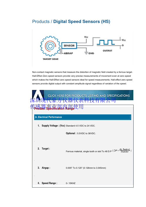
Products / Digital Speed Sensors (HS)Non-contact magnetic sensors that measure the distortion of magnetic field created by a ferrous target. Hall-Effect Zero speed sensors provide very precise measurements of movement even at zero speed which makes the Hall-Effect zero speed sensors ideal for speed measurements. Hall-effect zero speed sensors provide digital output with constant amplitude signal regardless of variation of the speed.Product Specification RangeA. Electrical Performance1. Supply Voltage : (Vcc)Standard 4.5 VDC to 24 VDC.Optional :5.5VDC to 36VDC.2. Target :Ferrous material, single tooth or slot To 48 D.P3. Airgap : 0.005" To 0.120" (0.126mm to 3.045mm)4. Speed Range : 0- 15KHZ深圳现代豪方仪器仪表科技有限公司 传感器事业部内部使用Optional:0 – 20KHZ5. Output Signal : NPN Open collector with 4.7k ohms internal pull-up Resistor (Digital).Optional :No pull-up resistor.6. Output Voltage : Low= 400mV Max High= Follows VccOptional :Low= 400 mV MaxHigh= 5 VDC7. Output Current :(I sink) 20mA continuous operationOptional :50mA8. Output Duty Cycle : 50% ±15% with equal size gear teeth and space between them9. Protection : Reverse Polarity.Optional :EMI , EMC, Input Transient Protection, Short circuitprotection.10. OperatingTemperature : -4° F to +221° F (-20°C to 105°C)Optional :-40° F to +302° F (-40°C to 150°C)深圳现代豪方仪器仪表科技有限公司 传感器事业部内部使用Automotive Engine Speed MeasurementDynamometerCrankshaftGearBox Speed SensorElectric speedometerFlywheel speed sensingHigh Performance vehicles speed and position sensingAerospaceElectric Power Generator Motor Speed MeasurementTurbine Flow MeasurementExercise Equipments Motor speed sensorFlow MeterLocomotive Crank shaft, Cam shaftMachineryTachometerOff-Highway深圳现代豪方仪器仪表科技有限公司 传感器事业部内部使用• True Zero Speed Sensing.• Constant Amplitude square wave (Digital) output• Reverse polarity protected• Wide Speed Range• Customized for most environment• Not sensitive to the orientation深圳现代豪方仪器仪表科技有限公司 传感器事业部内部使用。
汽车道路试验系统设计-开题报告
LabVIEW 中的 USB 接口通讯进行了研究,其系统采用了主从机结构,单片机构成的从机进行数据采 集,主机通过 LabVIEW 进行编程,为使主从机通过 USB 接口进行通讯,对 USB 接口的软、硬件进行 了设计,在 VC++环境下开发了相应的动态链接库作为驱动程序,实现了 USB 设备驱动的访问。以 上这些研究各有特点,在不断采用新技术的过程当中,根据各自的实际情对汽车道路试验测试系 统进行了相应的研究以满足不同的目的和需求(经济实用、功能齐全、精度高等),对探讨和促进 国内的汽车道路试验系统研究具有积极的意义。
毕业设计(论文)开题报告
学生姓名 指导教师姓名
院系 职称
汽车与交通工程学 院
教授
从事 专业
专业、班级 车辆工程 是否外聘 □是■否
题目名称
汽车道路试验系统设计
一、课题研究现状、选题目的和意义 (一)、研究现状 国外汽车道路试验研究现状:汽车道路试验数据采集与分析系统作为汽车整车试验的重要组成
部分,在发达国家已获得广泛研究和应用。目前,汽车道路试验技术以美国、日本、德国最为先进, 已研制出各种先进的随车专用传感器以及数据采集与分析系统,如非接触式传感器、方向盘力角测 量仪、踏板力计、燃油流量计、GPS 速度传感器以及便携式多通道试验数据采集装置等,可进行汽 车动力性能、经济性、制动性、平顺性、操作稳定性以及道路载荷谱采集等多种汽车道路试验。日 本小野测器公司生产的 DL-3000 系列汽车道路试验数据采集装置能在测量现场简单、迅速、高精度 地进行多通道测量记录。美国 B&B 公司以 NI 公司的 LabVIEW 和 PXI/SCXI 为平台,开发了车内测 试系统(IVDAS),该系统的 SCXI 机箱嵌入各种信号调理模块,模块的模式由信号种内决定,各种 信号采集与处理的整合由 LabVIEW 程序来完成。英国的 Racelogic 公司研制的 Vbox 测试系统是一 款以 GPS 信号作为数据分析来源的车辆性能测试系统,除常用的速度、距离、加减速度测量外还能 记录车辆移动轨迹,并在软件的操作下,实时画出跑道或山道的场地图,搭配实际轨迹与车速、G 值等数据,可分析车辆性能与驾驶状况。目前,国际上车辆性能检测仪器正向着智能化、高精度、 便携式、网络化、一体化方向发展。国外面向汽车道路试验主动安全性检测传感器和测试系统研发 的 公 司 主 要 有 德 国 Corrsys-Datron Sensor SystemInc. 、 瑞 士 KistlerInstrument AG 、 美 国 Michigan Scientific Corporation 、 美 国 MTS SystemsCorp. 、 日 本 株 式 会 社 共 和 电 业 (Kyowa Electronic Instruments Co.Ltd)、日本株式会社小野测器(Ono Sokki Co.Ltd)等。
Endevco 2222C 微型铂矿加速度传感器说明书

The Endevco ® model 2222C is the world’s most popular miniature piezoelectric accelerometer for vibration measurement on mini-structures and small objects.Its light weight (0.5 gm without the low-noise replaceable cable) effectively minimizes mass loading. Theaccelerometer is a self-generating device that requires no external power source for operation.The model 2222C features Endevco’s Piezite ® type P-8 crystal element operating in the radial shear mode. This sensor exhibits excellent output sensitivity stability over time. Signal ground is isolated from the mounting surface of the unit by a hard anodized surface. A specially designed low noise coaxial cable is supplied for error-free operation. Unit and cable removal tools are included in the package to ensure proper removal in the field.Endevco signal conditioner models 133, 2775B, 2771, 6634C or Oasis 2000 (4990A-X with cards 428 and/or 433) computer- controlled system are recommended for use with this high impedance accelerometer.•NEW! 2222C-R available as replacement sensor•Industry standard •Light weight (0.5 gm)•Adhesive mounting •Ground isolated•Small structure vibration measurement-20-15-10-505101520FREQUENCY IN HERTZ-30-10103050TEMPERATURE o F (o C)(-73)(10)(93)(177)STANDARD TOLERANCE INCHES (MILLIMETERS).XX = +/- .02 (.X = +/- .5).XXX = +/- .010 (.XX = +/- .25)FeaturesDescriptionModel 2222CPiezoelectric accelerometerSpecificationsThe following performance specifications conform to ISA-RP-37.2 (1964) and are typical values, referenced at +75˚F (+24˚C), 4 mA and 100 Hz, unless otherwise noted. Calibration data, traceable to National Institute of Standards and Technology (NIST), is suppliedUnitspC/g 1.4pC/g 1.0See typical amplitude response kHz 32kHz 25Hz 1 to 8000Hz 1 to 10 000Dynamic characteristicsCharge sensitivity Typical MinimumFrequency responseResonance frequency (typical) MinimumAmplitude response [1]±10% ±1 dB (ref)Temperature response See typical curve -67°F (-55°C) max/min % -15 / 0+350°F (+177°C) max/min % +15 / 0Transverse sensitivity % ≤5Amplitude linearity %1Per 200g, 0 to 2000 gAcceleration applied in the direction of the arrow on the unit produces positive output Electrical characteristicsOutput polarityResistance (with 3093M10-12 cable)GΩ ≥10at +350°F (+177°C) (with 3093M10-12 cable) GΩ ≥0.5MΩ ≥1 at 100 Vdc pF470Signal return isolated from mounting surface-100˚F to +350˚F (-73˚C to +177˚C)Sealed by silicone compound g pk 1000g pk10 000equiv. g pk/μ strain 0.04equiv. g pk/°F (/°C)0.05 (0.09)See outline drawing gm (oz) 0.5 (0.018)gm (oz)3.7 (0.13)Aluminum, hard anodized 3093-12 cable assembly Adhesive% 20 Hz to 10 000 HzpC/g %pFModel 2222CPiezoelectric accelerometerAccessoriesIsolation Capacitance GroundingEnvironmental characteristicsTemperature range Humidity [2]Sinusoidal vibration limit [3] Shock limit [4]Base strain sensitivityThermal transient sensitivityPhysical characteristicsDimensions Weight (sensor)Weight (cable-12’’ long) Case material Connector Mounting [5]CalibrationSupplied:Charge frequency response Charge sensitivityMaximum transverse sensitivity CapacitanceNotes:1. Low-end response of the transducer is a function of its associated electronics.2. Removing cable exposes accelerometer interior to environment. See Piezoelectric Instruction Manual before replacing cable assembly.3. When exposed to high g and large displacement, the cable must be tied down as close to the accelerometer as possible to prevent cable whip and subsequent cable failure.4. Short duration shock pulses, such as those generated by metal-to-metal impacts, may excite transducer resonance and cause linearity errors. See TP290 for more details.5. Adhesives such as petro-wax, hot-melt glue, and cyanoacrylate epoxy (super glue) may be used to mount the accelerometer temporarily to the test structure. To remove an epoxy-mounted accelerometer, first soften the epoxy with an appropriate solvent and then twist the unit off with the supplied removal wrench. Damage to sensors caused by inappropriate removal procedures are not covered by Endevco’s warranty.6. Maintain high levels of precision and accuracy using Endevco’s factory calibrationservices. Call Endevco’s inside sales force at 800-982-6732 for recommended intervals, pricing and turn-around time for these services as well as for quotations on ourstandard products.Continued product improvement necessitates that Endevco reserve the right to modify these specifications without notice. Endevco maintains a program of constant surveillance over all products to ensure a high level of reliability. This program includes attention to reliability factors during product design, the support of stringent Quality Control requirements, and compulsory corrective action procedures. These measures, together with conservative specifications have made the name Endevco synonymous with reliability.©Endevco (San Juan Capistrano), Inc. All Rights Reserved 30700 Rancho Viejo Road, San Juan Capistrano, CA 92675 USA (800)982-6732•(949)493-8181fax(949)661-7231••Email:************************100812。
非接触速度测试仪

非接触速度测试仪
非接触速度测试仪是用来检测机动车运动性能的仪器,该仪器有主机、非接触速度传感器、线缆三部分组成。
非接触速度传感器通过光学系统采集路面的信号,通过电子系统转换成速度信号传给主机;主机接受传感器的速度信号,通过计算得到各种信息,包括滑行、制动、加速、稳定车速等方面的详细信息,从而判断机动车的性能。
该仪器配备先进的非接触速度传感器,传感器是通过发出光到地面上,然后通过分析反射的光线得到机动车的速度,传感器具有安装操作简单,精度高等特点。
主机显示采用大屏幕液晶,可以实时显示速度、时间、曲线等参数;系统带有存储功能,可以存储检测结果;配有微型打印机,可以打印结果,配有计算机连接接口,可以与电脑连接0
该仪器适用于汽车产品质检部门、汽车综合性能检测线、汽车拖拉机生产厂家、大中专院校、农机检测部门、交通科研部门等。
光学发射光谱oes

光学发射光谱OES
光学发射光诸(OES) 是一种用于检测各种金属元索成分的分析技术。
它利用电磁光诺中的可见光诺和部分紫外光诺。
通过测量固体金属中从锂到铀的各种元索的特征光诺,进行定性和定量分析。
OES 技术可以对金属熔液、金属半成品/成品、金属加工业、管材、螺栓、棒材、线材、板材等进行检测。
其优点包括准确度高、精度高和检
出限低。
OES使用的发射光诺仪由光源、光学系统和计算机系统三大部分构成。
光源激发金属样品中的原子。
使其发射特征光谱。
光学系统中的衍射光栅将进入的光诺按波长色散开,然后通过对应的检测器测虽各个波长的诸线强度。
计算机系统获得测得的强度后,通过预设的校准程序对数据进行处理并得出元素浓度。
因此,OES可以进行定性分析/定量分析。
此外。
在应用方面,IPC-OES电感耦合等离子体发射光诸仪可用于地质、环境保护、化学工业、生物、医药、食品、冶金、农业等样品中70多种金属元素和-些非金属元素的定性和定量分析。
如需了解更多关于OES技术,建议咨询专业人士或查阅专业书籍。
索尼“Exmor R”CMOS新式传感器
佳能将新建一座年产量达到 5 0万台的工厂 。投 资的新工 5
厂计划明年初开工建设 。 可为所在地提供 5 0 0 0个工作岗位。 现 到了大大提高 , 最低保证的写入速度提升到 了 1MBS 5 /。 有的工厂年产量也 会大 幅度提升 。 TS 1 J一 闪传底座是与 Ta s re 闪传卡搭配使用的设备 。 rnf Jt e 体 由于喷墨打 印机 较高 的性价 比 , 少 的机 身体积 、 质的 积不大 , 更 优 长度稍长一些 。能够使 设备更好 的兼 容无 线传输功能 ,
打印质量 ,使喷 墨打印机受 到广大 中小 企业与 家庭 用户 的青 Tas r t rnf J 无线传输的距离很短 , ee 连接时要将相机或其他设备放 睐。同时加速 了打 印机 的普及 , 随着喷墨打 印机使用 需求 的不 在 T S 1 J一 闪传底座上方才可进行无线传输 。 断增加 , 喷墨打印机在市场中占据 了三分之二的份 额。 使用 时 , 打开相机 的 Ta s re功能 , rnf Jt e 然后直接把 相机 放在 现 在 佳 能 出 货 底座上 , 就可 以了。闪传底座靠 U B供 电, S S U B连接上 电脑或电 量为 每年 5 0万 台, 视等就会 自动开启 ,因为相机装有 Tasr t 6 r fJ 记忆棒的设备 , n ee 所 在 市场 中 占据 2 % 以信号灯会是亮 的。平放竖放都可以进行传输 。 0 的份额 , 为第 二大 成 近年来 , 随着数码 产品的不断发 展 , 存储卡的存储容量不断 打印机制造 商 , 佳能 得到提升 , 应用也快速普及 。 生产量 的大幅提高 , 新技术产品的出现都需要经过一段时间的成熟期 ,但 技术 会进 一 步 冲 击 市 场 的先进性引领着市场 的潮流走向。索尼存储卡技术的不 断创新 , 占有率 。 势必会带来 一场 全新变革 。 卵
Endress+Hauser LVU100 无接触超声波级别传感器简单型说明书

TRANSMISSOR DE NÍVEL ULTRASSÔNICO SEM CONTATOK-9U S ensor Compacto Simplescom Calibração Alvo e Indicadores LED de StatusU 4 Intervalos de Mediçãoaté 8 m (26') e Montagem do Transdutor com 1 ou 2" (25 a 50 mm)U L argura Mínima de Feixecom 5 cm (2") para Aplicações em Espaço RestritoU F aixa Morta de 5 cm (2")Otimiza a Capacidade de Preenchimento de Pequenos RecipientesU I nvólucro PC/ABS deClassificação NEMA 6 (IP67) com NEMA 4 X (IP65), OpcionalU I nteligência de SegurançaContra Falha com Retorno de Diagnóstico para Fácil Resolução de ProblemasA série L VU100 consiste em umtransmissor ultrassônico de 2 fios para uso geral. Ele fornece medição de nível sem contato até 8 m (26'), sendo recomendado para manipulação de materiais ultra puros, corrosivos, viscosos ou resíduos líquidos. O transmissor da Série L VU100 é utilizado frequentementeem armazenamento atmosférico em massa, tanques, poços coletores, reservatórios de processo, contentores intermédios para mercadorias a granel, tambores de 55 galões e aplicações em poços coletores. T aistransmissores são resistentes contra a ácido acético e resinas.ESPECIFICAçõES Intervalo: LVU104: 5 cm a 1,2 m (2" a 4')LVU109: 10 cm a 3 m (4" a 9,8')LVU116: 10 cm a 5 m (4" a 16,4')LVU126: 20 cm a 8 m (8" a 26,2')Exatidão: LVU104: 3 mm (0,125") LVU109/116/126: ±0,2% da extensãono ar Resolução: LVU104/109: 0,5 mm (0,019")LVU104, mostrado em escala reduzida.Série LVU100LVU116/126: 1 mm (0,039")Largura do feixe: LVU104/109: 5 cm (2") de diâmetro. LVU116/126: 7,6 cm (3") de diâmetro.Faixa Morta: LVU104: 5 cm (2") LVU109/116: 10 cm (4") LVU126: 20 cm (8")Indicação LED: Potência, calibração e diagnóstico Memória: Não volátil Tensão de Alimentação: 12 a 28 VCC Resistência de Loop: 500 Ω a 24 VCC Sinal de Saída: 4 a 20 mA, 2-fios Sinal Invertido: 4 a 20 mA ou 20 a 4 mA Calibração: Alvo, fio de calibração Segurança Contra Falha: Reverte-se para 22 mA Temperatura de Processo: -20 a 60°C (-4 a 140°F)Compensação de Temperatura: Automática Temperatura Eletrônica: -40 a 71°C (-40 a 160°F)Pressão: 30 psi (2 bar) a 25°C, desclassificada a 1,667 psi (0,115 bar) por °C acima de 25°C Classificação do invólucro: NEMA 6 (IP67), NEMA 4X (IP65), opcional Material do invólucro: PC/ABS FRMaterial do Transdutor:PVDF Material de Revestimento do Cabo: PP Cabo: 3-condutores, blindado, 3 m (10')Entrada de Conduíte: Duplo, 1⁄2 NPT na versão NEMA 4 (IP65)Montagem de Processo: LVU104/109: 1 NPT ou 1" G LVU116/126: 2 NPT ou 2" G Vedação de Montagem: FKM Classificação: Para uso geral Conformidade CE Para invólucro classificado NEMA 4X (IP65), acrescente "-NEMA4" ao número do modelo, por um custo adicional. (o cabo não é incluído com este modelo).Exemplos de Pedido: LVU116, transmissor de 2 fios, intervalo de 5 m (16,4'), montagem com 2 NPT , NEMA 6 Invólucro (IP67) com cabo de 3 m (10').LVU104-NEMA4, transmissor de 2 fios, intervalo de 1,2 m (4'), montagem com 1 NPT , opcionalNEMA 4X Invólucro (IP65).。
欧切斯EUS01光传感器说明书
上海欧切斯实业有限公司
产品介绍
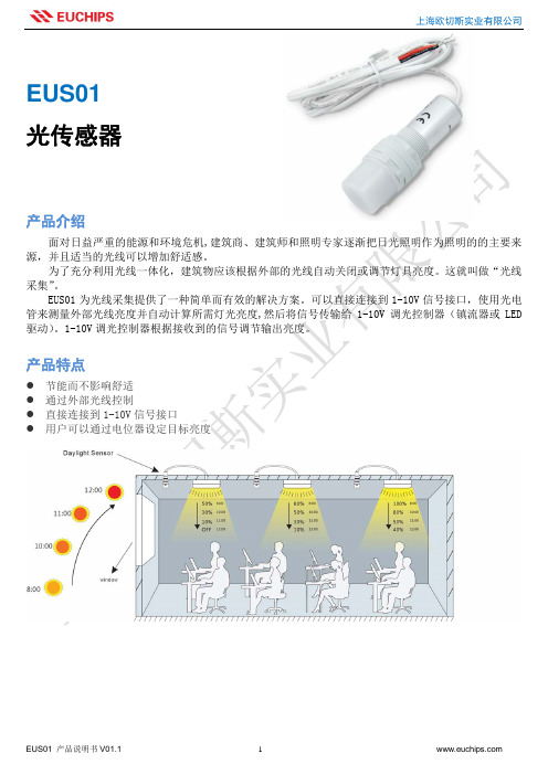
面对日益严重的能源和环境危机,建筑商、建筑师和照明专家逐渐把日光照明作为照明的的主要来 源,并且适当的光线可以增加舒适感。
为了充分利用光线一体化,建筑物应该根据外部的光线自动关闭或调节灯具亮度。这就叫做“光线 采集”。
EUS01 为光线采集提供了一种简单而有效的解决方案。可以直接连接到 1-10V 信号接口,使用光电 管来测量外部光线亮度并自动计算所需灯光亮度,然后将信号传输给 1-10V 调光控制器(镇流器或 LED 驱动)。1-10V 调光控制器根据接收到的信号调节输出亮度。
自然光线充足时,即 自然光线不足时,有 灯具根据外部自然光亮度 100%亮度输出,或调光维持预设 使有人进入感应区, 人进入感应区,灯具 亮度水平。 灯具也呈关闭状态。 自动开启。
当自然光线充足时,灯具立刻关 自然光线不足,当延时结束后,若没有人进入感应区,灯具将调至
闭,即使有人进入感应区。
待机亮度,待机时间结束后,关闭灯具。
设置
设置
为达到最佳效果,目标亮度水平应为灯具总照度的 40%-80%。
能够自动关 断 否 是 是
EUS01 产品说明书 V01.1
4
产品特点
z 节能而不影响舒适 z 通过外部光线控制 z 直接连接到 1-10V 信号接口 z 用户可以通过电位器设定目标亮度
EUS01 产品说明书 V01.1
1
EUS01+1-10V 调光控制器(任意品牌)
上海欧切斯实业有限公司
根据自然光亮度,灯具 100%亮度输出,或调光维持预设亮度 自然光线充足时,灯具 如有需要,用户
总结
EUS01 + 1-10V调光控制器 EUS01 + 微波感应开关 + 1-10V调光控制器 EUS01 +智能调光微波感应器 + 1-10V 调光 控制器
Omega OS137系列微型非接触红外温度传感器 发射器说明书

OS137 SERIESMiniature Non-Contact InfraredTemperature Sensor/Transmitter e-mail:**************For latest product manuals:Shop online at®User’s GuideIt is the policy of OMEGA Engineering, Inc. to comply with all worldwide safety and EMC/EMI regulations that apply. OMEGA is constantly pursuing certification of its products to the European New Approach Directives. OMEGA will add the mark to every appropriate device upon certification.The information contained in this document is believed to be correct, but OMEGA accepts no liability for any errors it contains, and reserves the right to alter specifications without notice.WARNING: These products are not designed for use in, and should not be used for, human applications.Table of ContentsSection PageCaution & Safety Information (iii)Safety Warnings and IEC Symbols (iii)Section 1 Introduction (1)Section 2 Installation (1)2.1 Unpacking (1)2.2 Electrical Connection (2)Section 3 Operation (3)3.1 Measuring Temperature (3)3.2 Ambient Temperature (4)3.3 Atmospheric Quality (4)3.4 Alarm Setting (6)Section 4 Laser Sight Accessory (7)4.1 Warnings and Caution (7)4.2 Operating the Laser Sight Accessory (7)Section 5 Specifications (9)5.1 General (9)5.2 Laser Sight Accessory (10)Section 6 Emissivity T ables (11)iTable of FiguresFigure Description Page2-1General Wiring Diagram (2)2-2Alarm Output Wiring Diagram (2)3-1Optical Field of View (3)3-2Location of Emissivity & Alarm Adjust and Alarm Switch (3)3-3Mounting Bracket, OS137-MB (4)3-4Air Purge Collar, OS137-AP (4)3-5Stainless Steel Housing (5)3-6Water/Air Cool Jacket, OS137-WC (5)4-1Laser Sighting Accessory, OS137-LS (8)4-2Laser Warning Label (8)iiiiiCAUTION & SAFETY INFORMATIONIf the equipment is used in a manner not specified in this manual, the protection provided by the equipment may be impaired.The Installation category is one (1).There is no user replaceable fuse in this product.The output terminals of this product are for use with equipment (digital meters,chart recorders, etc.) which have no accessible live parts. Such equipment should comply with all the applicable safety requirements.Do not operate the equipment in flammable or explosive environments.The unit comes with a 1.82 m (6') shielded cable for power and outputconnections. The cable is a multi-conductor, 24 AWG stranded wire with the rating of 600 VDC, 205ºC (401°F) Teflon ®insulation.Power must be disconnected before making any electrical connections.The recommended power supply should be VDE or UL approved. Rating:12-24VDC @ 50 mA mininum power with overload protection.The supply voltage to the transmitter should not exceed 24 VDC.SAFETY WARNINGS AND IEC SYMBOLSThis device is marked with international safety and hazardous symbols inaccordance with IEC1010. It is important to read and follow all the precautions and instructions in this manual before operating or commissioning this device as it contains important information relating to safety and EMC. Failure to follow all the safety precautions may result in injury and/or damage to yourequipment.IEC Symbol DescriptionCaution - Refer to the accompanyingdocument(s).Direct CurrentLaser SymbolSECTION 1 - INTRODUCTIONThe OS137 Series is a precision, miniature infrared transmitter. It measurestemperature via non-contact, and provides an analog output proportional to themeasured temperature. The OS137 Series is offered in three temperature ranges:0 to 100ºC (32 to 212ºF), -18 to 260ºC (0 to 500ºF) and -18 to 538ºC (0 to 1000ºF).The analog output is offered as 4 to 20 mA, 0 to 5 Vdc, 0 to 10 Vdc, 10mV/degree C or F, or K type thermocouple.The unit provides adjustable emissivity from 0.5 to 1.0, 10 to 1 optical field ofview, and field adjustable alarm output.The super-compact design, 25.4 mm OD x 127 mm length (1.0" OD x 5.0" L) isideal to measure temperature in confined, and hard to reach places. The StainlessSteel housing is NEMA-4 rated. The unit comes standard with a 1.82 m (6')shielded cable.SECTION 2 – INSTALLATION2.1 – UnpackingRemove the packing list and verify that you have received all your equipment. Ifyou have any questions about the shipment, please call OMEGA CustomerService at:1-800-622-2378 or 203-359-1660. We can also be reached on the internet atemail:******************When you receive the shipment, inspect the container and the equipment for anysigns of damage. Note any evidence of rough handling in transit. Immediatelyshipping materials are saved for inspection. Afterexamination and removal of contents, save packing materialand carton in the event that reshipment is necessary.The following items are supplied in the box:• The infrared transmitter, OS137 with the 1.82 m (6') shielded cable.• Two mounting nuts• The User’s GuideThe following describes the ordering information:OS137 – * – ** , where- * means:-1 : 0 to 100°C (32 to 212ºF) temperature range-2 : -18 to 260ºC (0 to 500ºF) temperature range-3 : -18 to 538°C (0 to 1000°F) temperature range- ** means:-MA : 4 to 20 mA current output-V1 : 0 to 5 Vdc output-V2 : 0 to 10 Vdc output1-K : K type thermocouple output-MVC : 10 mV/ºC output-MVF : 10 mV/ºF outputFor longer power/output cable, add suffix “xxFT” to the model part number.The following table lists the optional accessories:2.2 – Electrical ConnectionThe shielded cable provides the power and output connections. Fig 2-1 showsthe wiring diagram for different analog outputs. Fig. 2-2 shows alarm outputApply DC power after making all the wiring connections2SECTION 3 – OPERATION3.1 – Measuring TemperatureBefore starting to measure temperature, make sure the following check list is met:ߜThe power and output connections are made (Fig 2-1).ߜThe target is larger than the optical field of view of the transmitter (Fig 3-1).ߜ Use the Laser Sighting accessory (optional), to align the transmitter to thecenter of the target area.ߜ Remove the End Cap to get to the Emissivity Single Turn Pot (Fig. 3-2). Set the Emissivity Pot based on the target surface. Then put back the End Cap.ߜ Make sure the output load is within the product specification.Figure 3-1. Optical Field of ViewFigure 3-2. Location of Emissivity & Alarm Adjust and Alarm Switch33.2 – Ambient TemperatureThe transmitter can operate in an ambient temperature of 0 to 70°C (32 to 158°F)without any water cool jacket. It can operate from 0 to 200°C (32 to 392°F) withthe water cool jacket accessory, OS137-WC (Fig 3-6 & 3-7). It can operate up to110°C (230°F) with air cooling.There is a warm up period of 1 to 2 minutes after power up. After the warm upperiod, temperature measurement can be made.When the ambient temperature around the transmitter changes abruptly, the sensor headgoes through a thermal shock. It takes a certain amount of time for the sensor head to getstabilized to the new ambient temperature. For example, it takes about 30 minutes for thetransmitter to stabilize from the 25°C to 50°C (77°F to 122°F) ambient temperature.3.3 - Atmospheric QualityEnvironments with smoke, dust, and fumes dirty up the optical lens, and causeerroneous temperature readings. To keep the surface of the optical lens clean, theair purge collar accessory is recommended, OS137-AP (Fig 3-4).The following figures show the Mounting Bracket (OS137-MB), Air Purge Collar(OS137-AP), Stainless Steel Housing and Water/Air Cool Jacket (OS137-WC),with built-in air purge collar.Figure 3-3. Mounting Bracket, OS137-MB4Figure 3-5. Stainless Steel HousingFigure 3-6. Water/Air Cool Jacket, OS137-WC 53.4Alarm SettingThe unit provides 0-100% alarm setpoint adjustment. Here is an exampleof an alarm setting:• An OS137-3-MA (4/20 mA output), the alarm is to be set at 204°C(400°F) temperature.• Connect the alarm output as shown in Fig. 2-2.• Remove the End Cap to get to the Alarm Switch and the Alarm Adjust(Fig. 3-2).• Set the Slide Switch on the main board to the Alarm position (2).• Measure the analog output, and adjust the Alarm Potentiometer untilthe output reads 10.4 mA which is 40% (204°C, 400°F) of thetemperature range -18 to 538°C, (0 to 1000°F)40 x (20-4)+ 4][10.4mA =100• Set the Alarm Slide Switch back to the Real Time position (1).• If the temperature reading is below the alarm setpoint, the AlarmOutput stays low, otherwise it goes high (Alarm Condition).• The Alarm Output can drive an external mechanical relay.6SECTION 4 - LASER SIGHT ACCESSORY4.1 – Warnings and CautionYou may receive harmful laser radiation exposure if you donot adhere to the warnings listed below:• USE OF CONTROLS OR ADJUSTMENTS OR PERFORMANCE OFPROCEDURES OTHER THAN THOSE SPECIFIED IN THIS GUIDE MAYRESULT IN HAZARDOUS RADIATION EXPOSURE.• DO NOT LOOK AT THE LASER BEAM COMING OUT OF THE LENS ORVIEW IT DIRECTLY WITH OPTICAL INSTRUMENTS – EYE DAMAGE CANRESULT.• USE EXTREME CAUTION WHEN OPERATING THE LASER SIGHTACCESSORY.• NEVER POINT THE LASER ACCESSORY AT A PERSON.• KEEP THE LASER SIGHT ACCESSORY OUT OF REACH OF ALLCHILDREN.Do not attempt to open the laser sight accessory. There are nouser serviceable parts inside.4.2 – Operating the Laser Sight AccessoryThe laser sight accessory screws onto the front of the transmitter sensor head.This accessory is only used for alignment of the transmitter head to the targetarea. After the alignment process, the accessory has to be removed from the frontof the transmitter head before temperature measurement is made.The laser sight accessory is powered from a small, compact battery pack(included with the accessory). Connect the battery pack to the accessory usingthe cable provided. Aim at the target, and turn on the battery power using theslide switch on the battery pack. Adjust the sensor head position so that the laserbeam points to the center of the target area. Turn off the battery pack, andremove the laser sighting accessory from the sensor head (Fig 4-1).7Figure 4-2. Laser Warning Label89SECTION 5 – SPECIFICATIONS5.1 - General T emperature Range:OS137-10 to 100ºC (32 to 212ºF)OS137-2-18 to 260ºC (0 to 500ºF)OS137-3-18 to 538°C (0 to 1000°F)Accuracy: @22ºC (72ºF) ambient 1.5% of Rdg or 2.0ºC (3.5ºF) whichever is greater Emissivity of 0.95 or greater Repeatability:1% of Rdg or 1.0ºC (2.0ºF) whichever is greater Field of View:10 to 1Spectral Response:8 to 14 microns Response Time:150 msec, 0 to 63% of final value Emissivity:0.5 to 1.0, adjustable via Single Turn Pot Alarm Output:Voltage, 100 mA Drive Alarm Set Point:0 to 100% Adj., set via Pot Analog output:MA 4 to 20 mA V10 to 5 Vdc V20 to 10 Vdc K K type thermocouple, compensated MVC 10 mV/ºC MVF 10 mV/ºF Output Load Requirements:Min. Load (0 to 5 Vdc) 2 K-Ohms Min. Load (0 to 10 Vdc) 4 K-Ohms Max. Load (4 to 20 mA)(Power Supply – 4)/20 mA Min. Load (10 mV/Deg)10 K-Ohms Min. Load (K T/C)100 K-Ohms Operating Ambient T emperature:No Water Cooling 0 to 70ºC (32 to 158ºF)With Water Cooling (OS136-WC)0 to 200ºC (32 to 392ºF)With Air Cooling (OS136-WC)0 to 110°C (32 to 230°F)Operating Relative Humidity:Less than 95% RH, non-condensing Water Flow Rate for OS136-WC:0.25 GPM, room temperature, minimum Air Flow Rate for OS136-WC 5 CFM (2.4 liters/sec)Warm up Period: 1 to 2 minutes Thermal Shock:About 30 minutes for 25ºC (77°F) abrupt ambient temperature change Air Flow Rate for Air Purge Collar 1 CFM (0.5 liters/sec.)T ransmitter Housing:Stainless Steel 316, NEMA-4 & IP65 rated Power:12 to 24 VDC @ 50 mA Dimensions:25.4 OD x 127 L mm (1.0" OD x 5.0" L)Weight:0.80 lb (363 g)5.2 - Laser Sight AccessoryLaser Wavelength (Color):630 - 670 nm (red)Operating Distance:Up to 9.1 m (30 ft)Max. Laser Power Output:Less than 1 mW @ 22ºC (72°F) ambientEuropean Classification:Class 2, EN60825-1/11.2001FDA Classification:Class II Laser Product. Complies with21 CFR 1040.10Laser Beam Diameter:Less than 5 mmBeam Divergence:Less than 2 mradOperating T emperature:0 to 50°C (32 to 122°F)Operating Relative Humidity:Less than 95% RH, non-condensingPower Switch:ON/OFF, Slide Switch on the battery packPower Indicator:Red LEDPower:Battery pack, 3 VDCCaution & Certification Label:Located on the head sight circumferenceIdentification Label:Located on the head sight circumferenceAperture Label:Located on the head sight circumferenceDimensions:38 OD x 50.8 L mm (1.5" OD x 2" L)1011Material Emissivity (ε) Aluminum– pure highly polished plate. . . . . . . . . . . . . . . . . . . . . . . . 0.04 to 0.06 Aluminum– heavily oxidized. . . . . . . . . . . . . . . . . . . . . . . . . . . . . . . 0.20 to 0.31 Aluminum– commercial sheet. . . . . . . . . . . . . . . . . . . . . . . . . . . . . . . . . . . . 0.09 Brass– dull plate. . . . . . . . . . . . . . . . . . . . . . . . . . . . . . . . . . . . . . . . . . . . . . 0.22 Brass– highly polished, 73.2% Cu, 26.7% Zn. . . . . . . . . . . . . . . . . . . . . . . . . 0.03 Chromium– polished. . . . . . . . . . . . . . . . . . . . . . . . . . . . . . . . . . . . . 0.08 to 0.36 Copper– polished. . . . . . . . . . . . . . . . . . . . . . . . . . . . . . . . . . . . . . . . . . . . . 0.05 Copper– heated at 600°C (1112°F). . . . . . . . . . . . . . . . . . . . . . . . . . . . . . . 0.57 Gold– pure, highly polished or liquid. . . . . . . . . . . . . . . . . . . . . . . . . 0.02 to 0.04 Iron and steel (excluding stainless)– polished iron. . . . . . . . . . . . . . . . 0.14 to 0.38 Iron and steel (excluding stainless)– polished cast iron. . . . . . . . . . . . . . . . . . . 0.21 Iron and steel (excluding stainless)– polished wrought iron. . . . . . . . . . . . . . . 0.28 Iron and steel (excluding stainless)– oxidized dull wrought iron. . . . . . . . . . . . 0.94 Iron and steel (excluding stainless)– rusted iron plate. . . . . . . . . . . . . . . . . . . 0.69 Iron and steel (excluding stainless)– polished steel. . . . . . . . . . . . . . . . . . . . . . 0.07 Iron and steel (excluding stainless)– polished steel oxidized at600°C (1112°F). . . . . . . . . . . . . . . . . . . . 0.79 Iron and steel (excluding stainless)– rolled sheet steel. . . . . . . . . . . . . . . . . . . 0.66 Iron and steel (excluding stainless)– rough steel plate. . . . . . . . . . . . . 0.94 to 0.97 Lead– gray and oxidized. . . . . . . . . . . . . . . . . . . . . . . . . . . . . . . . . . . . . . . 0.28 Mercury. . . . . . . . . . . . . . . . . . . . . . . . . . . . . . . . . . . . . . . . . . . . . 0.09 to 0.12 Molybdenum filament. . . . . . . . . . . . . . . . . . . . . . . . . . . . . . . . . . . . 0.10 to 0.20 Nickel– polished. . . . . . . . . . . . . . . . . . . . . . . . . . . . . . . . . . . . . . . . . . . . . 0.07 Nickel– oxidized at 649 to 1254°C (1200 t o 2290°F). . . . . . . . . . . . 0.59 to 0.86 Platinum– pure polished plate. . . . . . . . . . . . . . . . . . . . . . . . . . . . . . 0.05 to 0.10 Platinum– wire. . . . . . . . . . . . . . . . . . . . . . . . . . . . . . . . . . . . . . . . 0.07 to 0.18 Silver– pure and polished. . . . . . . . . . . . . . . . . . . . . . . . . . . . . . . . . 0.02 to 0.03 Stainless steel– polished. . . . . . . . . . . . . . . . . . . . . . . . . . . . . . . . . . . . . . . . 0.07 Stainless steel– Type 301 at 232 to 941°C (450 to 1725°F). . . . . . . . . 0.54 to 0.63 Tin– bright. . . . . . . . . . . . . . . . . . . . . . . . . . . . . . . . . . . . . . . . . . . . . . . . . 0.06 Tungsten– filament. . . . . . . . . . . . . . . . . . . . . . . . . . . . . . . . . . . . . . . . . . . . 0.39 Zinc– polished commercial pure. . . . . . . . . . . . . . . . . . . . . . . . . . . . . . . . . . 0.05 Zinc– galvanized sheet. . . . . . . . . . . . . . . . . . . . . . . . . . . . . . . . . . . . . . . . . 0.23 METALS12Material Emissivity (ε)Asbestos Board . . . . . . . . . . . . . . . . . . . . . . . . . . . . . . . . . . . . . . . . . . . . . . .0.96Asphalt, tar, pitch . . . . . . . . . . . . . . . . . . . . . . . . . . . . . . . . . . . . . . .0.95 to 1.00Brick – red and rough . . . . . . . . . . . . . . . . . . . . . . . . . . . . . . . . . . . . . . . . . .0.93Brick – fireclay . . . . . . . . . . . . . . . . . . . . . . . . . . . . . . . . . . . . . . . . . . . . . . .0.75Carbon – filament . . . . . . . . . . . . . . . . . . . . . . . . . . . . . . . . . . . . . . . . . . . . .0.53Carbon – lampblack - rough deposit . . . . . . . . . . . . . . . . . . . . . . . . . .0.78 to 0.84Glass - Pyrex, lead, soda . . . . . . . . . . . . . . . . . . . . . . . . . . . . . . . . . .0.85 to 0.95Marble – polished light gray . . . . . . . . . . . . . . . . . . . . . . . . . . . . . . . . . . . . .0.93Paints, lacquers, and varnishes – Black matte shellac . . . . . . . . . . . . . . . . . . . .0.91Paints, lacquers, and varnishes – aluminum paints . . . . . . . . . . . . . . . .0.27 to 0.67Paints, lacquers, and varnishes – flat black lacquer . . . . . . . . . . . . . . .0.96 to 0.98Paints, lacquers, and varnishes – white enamel varnish . . . . . . . . . . . . . . . . . .0.91Porcelain – glazed . . . . . . . . . . . . . . . . . . . . . . . . . . . . . . . . . . . . . . . . . . . . .0.92Quartz – opaque . . . . . . . . . . . . . . . . . . . . . . . . . . . . . . . . . . . . . . . .0.68 to 0.92Roofing Paper . . . . . . . . . . . . . . . . . . . . . . . . . . . . . . . . . . . . . . . . . . . . . . .0.91Tape – Masking . . . . . . . . . . . . . . . . . . . . . . . . . . . . . . . . . . . . . . . . . . . . . .0.95Water . . . . . . . . . . . . . . . . . . . . . . . . . . . . . . . . . . . . . . . . . . . . . . . .0.95 to 0.96Wood – planed oak . . . . . . . . . . . . . . . . . . . . . . . . . . . . . . . . . . . . . . . . . . . .0.90N O N M E T A L SNOTES: 13WARRANTY/DISCLAIMEROMEGA ENGINEERING, INC. warrants this unit to be free of defects in materials and workmanship for a period of 13 months from date of purchase. OMEGA’s WARRANTY adds an additional one (1) month grace period to the normal one (1) year product warranty to cover handling and shipping time. This ensures that OMEGA’s customers receive maximum coverage on each product.If the unit malfunctions, it must be returned to the factory for evaluation. OMEGA’s Customer Service Department will issue an Authorized Return (AR) number immediately upon phone or written request.Upon examination by OMEGA, if the unit is found to be defective, it will be repaired or replaced at no charge. OMEGA’s WARRANTY does not apply to defects resulting from any action of the purchaser,including but not limited to mishandling, improper interfacing, operation outside of design limits, improper repair, or unauthorized modification. This WARRANTY is VOID if the unit shows evidence of having been tampered with or shows evidence of having been damaged as a result of excessive corrosion;or current, heat, moisture or vibration; improper specification; misapplication; misuse or other operating conditions outside of OMEGA’s control. Components in which wear is not warranted, include but are not limited to contact points, fuses, and triacs.OMEGA is pleased to offer suggestions on the use of its various products. However, OMEGA neither assumes responsibility for any omissions or errors nor assumes liability for any damages that result from the use of its products in accordance with information provided by OMEGA, either verbal or written. OMEGA warrants only that the parts manufactured by the company will be as specified and free of defects. OMEGA MAKES NO OTHER WARRANTIES OR REPRESENTATIONS OF ANY KIND WHATSOEVER, EXPRESSED OR IMPLIED, EXCEPT THAT OF TITLE, AND ALL IMPLIED WARRANTIES INCLUDING ANY WARRANTY OF MERCHANTABILITY AND FITNESS FOR A PARTICULAR PURPOSE ARE HEREBY DISCLAIMED. LIMITATION OF LIABILITY: The remedies of purchaser set forth herein are exclusive, and the total liability of OMEGA with respect to this order, whether based on contract, warranty, negligence, indemnification, strict liability or otherwise, shall not exceed the purchase price of the component upon which liability is based. In no event shall OMEGA be liable for consequential, incidental or special damages.CONDITIONS: Equipment sold by OMEGA is not intended to be used, nor shall it be used: (1) as a “Basic Component” under 10 CFR 21 (NRC), used in or with any nuclear installation or activity; or (2) in medical applications or used on humans. Should any Product(s) be used in or with any nuclear installation or activity, medical application, used on humans, or misused in any way, OMEGA assumes no responsibility as set forth in our basic WARRANTY /DISCLAIMER language, and, additionally, purchaser will indemnify OMEGA and hold OMEGA harmless from any liability or damage whatsoever arising out of the use of the Product(s) in such a manner.RETURN REQUESTS/INQUIRIESDirect all warranty and repair requests/inquiries to the OMEGA Customer Service Department. BEFORE RETURNING ANY PRODUCT(S) TO OMEGA, PURCHASER MUST OBTAIN AN AUTHORIZED RETURN (AR) NUMBER FROM OMEGA’S CUSTOMER SERVICE DEPARTMENT (IN ORDER TO AVOID PROCESSING DELAYS). The assigned AR number should then be marked on the outside of the return package and on any correspondence.The purchaser is responsible for shipping charges, freight, insurance and proper packaging to prevent breakage in transit.FOR WARRANTY RETURNS, please have thefollowing information available BEFOREcontacting OMEGA:1.Purchase Order number under which the productwas PURCHASED,2.Model and serial number of the product underwarranty, and3.Repair instructions and/or specific problemsrelative to the product.FOR NON-WARRANTY REPAIRS,consult OMEGA for current repair charges. Have the following information available BEFORE contacting OMEGA:1. Purchase Order number to cover the COST of the repair,2.Model and serial number of the product, and 3.Repair instructions and/or specific problems relative to the product.OMEGA’s policy is to make running changes, not model changes, whenever an improvement is possible. This affords our customers the latest in technology and engineering.OMEGA is a registered trademark of OMEGA ENGINEERING, INC.© Copyright 2012 OMEGA ENGINEERING, INC. All rights reserved. This document may not be copied, photocopied,reproduced, translated, or reduced to any electronic medium or machine-readable form, in whole or in part, without theprior written consent of OMEGA ENGINEERING, INC.Where Do I Find Everything I Need for Process Measurement and Control?OMEGA…Of Course!Shop online at SMTEMPERATUREⅪߜThermocouple, RTD & Thermistor Probes, Connectors, Panels & AssembliesⅪߜWire: Thermocouple, RTD & ThermistorⅪߜCalibrators & Ice Point ReferencesⅪߜRecorders, Controllers & Process MonitorsⅪߜInfrared PyrometersPRESSURE, STRAIN AND FORCEⅪߜTransducers & Strain GagesⅪߜLoad Cells & Pressure GagesⅪߜDisplacement TransducersⅪߜInstrumentation & AccessoriesFLOW/LEVELⅪߜRotameters, Gas Mass Flowmeters & Flow ComputersⅪߜAir Velocity IndicatorsⅪߜTurbine/Paddlewheel SystemsⅪߜTotalizers & Batch ControllerspH/CONDUCTIVITYⅪߜpH Electrodes, Testers & AccessoriesⅪߜBenchtop/Laboratory MetersⅪߜControllers, Calibrators, Simulators & PumpsⅪߜIndustrial pH & Conductivity EquipmentDATA ACQUISITIONⅪߜData Acquisition & Engineering SoftwareⅪߜCommunications-Based Acquisition SystemsⅪߜPlug-in Cards for Apple, IBM & CompatiblesⅪߜData Logging SystemsⅪߜRecorders, Printers & PlottersHEATERSⅪߜHeating CableⅪߜCartridge & Strip HeatersⅪߜImmersion & Band HeatersⅪߜFlexible HeatersⅪߜLaboratory HeatersENVIRONMENTALMONITORING AND CONTROLⅪߜMetering & Control InstrumentationⅪߜRefractometersⅪߜPumps & TubingⅪߜAir, Soil & Water MonitorsⅪߜIndustrial Water & Wastewater TreatmentⅪߜpH, Conductivity & Dissolved Oxygen InstrumentsM4015/0512。
OMRON EE-SX1103 微型光电传感器 [透过型] 说明书
![OMRON EE-SX1103 微型光电传感器 [透过型] 说明书](https://img.taocdn.com/s3/m/fa0e5516866fb84ae45c8d78.png)
CSM_EE-SX1103_DS_C_1_162EE-SX1103微型光电传感器[透过型]■电气及光学特性 (Ta = 25°C)项目记号特性值单位条件MIN.TYP.MAX.发光侧正向电压V F —— 1.3 1.6V I F = 50mA 反向电流I R ————10μA V R = 5V 最大发光波长λ P ——950——nmI F = 50mA受光侧光电流I L 0.5————mA I F = 20mA ,V CE = 5V 暗电流I D ————500nA V CE = 10V ,0 l x泄漏电流I LEAK——————μA —————集电极发射极之间的饱和电压V CE (sat)————0.4V I F = 20mA ,I L = 0.3mA 最大光谱灵敏度波长λ P ——800——nm V CE = 5V上升时间t r ——10——μs V CC = 5V ,R L = 100ΩI F = 20mA下降时间t f——10——μsV CC = 5V ,R L = 100ΩI F = 20mA■外形尺寸(单位:mm )■特征•实现传感器宽度 5mm 、凹槽宽度 2mm 的超小型传感器•印刷线路板实装型•高分辨率(狭片宽度 0.4mm )■绝对最大额定值 (Ta = 25°C)项目记号额定值单位发光侧正向电流I F 50mA 正向脉冲电流I FP ——A 反向电压V R 5V 受光侧集电极发射极之间的电压V CEO 30V 发射极集电极之间的电压V ECO 4.5V 集电极电流I C 30mA 集电极损耗P C 80mW 动作温度Topr -25~+85℃保存温度Tstg -30~+100℃焊接温度Tsol260℃*1环境温度超过 25℃ 时,请参阅温度额定值图。
*2焊接时间请控制在 3 秒以内*1*1*2EE-SX110363E E S X 1103-微型光电传感器■额定值·特性曲线图 1.正向电流·集电极损耗的温度额定值图图 2.正向电流—正向电压特性 (TYP.)图 3.光电流—正向电流特性 (TYP.)图 4.光电流—集电极发射极之间的电压特性 (TYP.)图 5.相对光电流—环境温度特性 (TYP.)图 6.暗电流—环境温度特性 (TYP.)图 7.应答时间—光电流特性 (TYP.)图 8.检测位置特性 (TYP.)图 9.检测位置特性 (TYP.)图 10.应答时间测定回路。
马波斯非接触式测量仪的组成

马波斯(Marposs)非接触式测量仪是一种精密测量工具,主要用于在工业生产环境中实时监控和精确测量工件的各种物理参数,如位移、厚度、表面形貌、温度、扭矩和进给力等,而无需直接接触被测对象,从而避免了对工件造成潜在损害以及由于机械磨损带来的测量误差。
马波斯非接触式测量仪通常包含以下核心组成部分:1.传感器模块:o电涡流传感器:用于检测金属工件的位移、振动和厚度变化,尤其适用于在线监测机床主轴或刀具的状态。
o光学传感器:通过激光或红外线技术来实现高精度的位置、距离、速度和角度测量,如测量转动部件的转速和扭矩。
o压电传感器:可用来检测微小的压力变化,进而转化为相应的力或扭矩数据。
2.信号处理单元:o接收传感器发送的原始信号,对其进行放大、滤波和数字化处理,确保信号质量可靠且不受噪声干扰。
3.数据采集系统(DAQ):o实时捕获和记录传感器数据,可以配备有先进的软件算法进行数据分析,计算出例如刀具磨损状态、扭矩偏差等关键指标。
4.控制器/处理器:o对测量数据进行实时解析和判断,当检测到超出预设阈值的情况时,能够触发报警或自动调整机床的运行参数。
5.用户界面/显示器:o提供可视化操作和数据显示,包括实时测量数值、趋势图、报警信息等,便于操作人员监控和诊断生产过程。
6.通信接口:o支持与其他设备或工厂自动化系统的集成,如通过现场总线协议(如Profinet、Ethernet/IP、EtherCAT等)或者网络通信实现远程控制和数据传输。
7.安装附件和支架:o包括各种定制化的安装支架、导轨和定位装置,以确保传感器准确、稳定地安装在合适的检测位置上。
通过上述各部分的有效配合,马波斯非接触式测量仪能够在复杂的工业环境中提供高效、准确的在线监测解决方案,显著提升产品质量和生产效率。
光电非接触式工作原理

光电非接触式工作原理
光电非接触式工作原理是指通过光电传感器,实现物体的非接触式检测和测量。
其基本原理是利用光电传感器将光信号转化为电信号,并通过处理电信号来实现对物体的检测和测量。
具体工作原理如下:
1. 发射光束:光电非接触式系统中通常会使用发射器发射一束光束。
2. 接收光信号:光束照射到被检测物体上,被检测物体会反射一部分光线。
光电传感器会接收到这部分光线并将其转变为电信号。
3. 光信号转换:光电传感器中的光敏器件会将接收到的光信号转换为电信号。
4. 电信号处理:电信号被传送到信号处理器,经过处理后,可以得到物体的一些信息,如位置、距离、速度等。
5. 输出结果:最终处理后的结果可以通过显示屏、蜂鸣器等方式进行输出。
需要注意的是,光电非接触式工作原理可以有多种实现方式,如使用光电开关、光电编码器等设备,具体原理可能会有所不同。
以上仅为一般的工作原理示意。
茂名防爆直线位移传感器工作原理

茂名防爆直线位移传感器工作原理
防爆直线位移传感器(LSIS)是一种可用于防止爆炸性环境中的液体和固体物体位移的传感器。
茂名(Monsanto)是一家专门设计、制造防爆直线位移传感器的公司,在这里,我们将研究其传感器的原理和用途。
首先,茂名的防爆直线位移传感器采用了最新的红外技术,采用独特的高精度方案。
它使用精确的高精度光电元件和石英晶体管,它是一种永不老化的产品,不会因正常工作而损坏或损失性能。
它的重点是检测和数据采集,使它能够测量和监测液体和固体物体的静止或移动,以及位移速度。
在防爆环境中,它可用于实时监测液体和固体物体的位移,大大提高了安全性。
此外,茂名的防爆直线位移传感器配备了高可靠的温湿度传感器,可以监测温度和湿度,并通过电子报告进行通知。
此外,它还能够识别气体污染,警报,以采取紧急行动。
此外,茂名的防爆直线位移传感器也兼容智能手机和电脑设备,实现了远程监测,甚至可以实现远程控制。
其灵活性和可靠性使其成为工厂数字化自动化的理想选择。
茂名的防爆直线位移传感器具有较高的性能成本比,可以有效的降低客户的使用成本。
此外,它的定位技术可以提供准确的精度,稳定输出和高可靠性,可以满足客户的定位需求。
总之,茂名的防爆直线位移传感器具有以上优点,可以灵活、高效、可靠地监测复杂的防爆环境,为用户提供更高的安全性。
由于其
高精度、低成本和高可靠性,它也是工厂自动化解决方案的理想选择。
光电式电流互感器的研究
应 的解 决 办法 。 35 温度 的影 响 .
实 际应 用 中 , 由于输 出二 次 电压 与 一次 电流 的 倒数 成 正 比 , 在相 位上 二 者 相 差 9。这 样需 要 在 线 路 里加 故 0,
一
子电路处理的是电压信号, 所以在这种互感器 中通常需 要一个 积分 器把 电流 信 号变 换 为 电压 信 号 , 因此 如何 设
计专用 的积分器 也是设 计 的一个 主要 难点 。
34 双折射 效应 的影 响 .
宝一 =
丌 r
:
所 有 的单 模光 纤 都存 在 着 线 性 双 折 射 现象 , 这是 因 为纤芯 结 构在 折 射 率 或 者 直 径 方 面 不 会 是 完 全 的 圆 对
而对一定 的材 料来 说 , / 2和 为 定 值 。从 公 式 中看 出旋
熟 和市 场 需求 的增 加 , 内一 些有 实 力 的 集 团 和厂 家 开 国 始 和 高校 合作 , 同研 制 。19 年 清华 大 学 和 中 国电 力 共 91
转角 0 与磁 场 的的大小 成正 比变化 。 () 2 工作原 理 图1 为一 种无 源型光 电式 电流 互感 器 的基本 结 构 示
字信号 , 然后驱动光 源( 发光二极管 ~D 将数字电信号转 L ), E
Rgwk线圈是 一 种 较 成 熟 的 测 量 元 件 , oosi 因其 频 率 响应好 、 确度 高 、 准 结构简 单且 成本低 廉 而被公认 为是 较
理 想 的母线 电流采样 元 件 。R gw k 线 圈是 将 导线 均 匀 oo si 绕 制在 非磁 性骨 架 上 的空 心 线 圈 , 由于他 不 与 被i 电路 贝 4
电感耦合等离子体发射光谱仪 辐射

电感耦合等离子体发射光谱仪辐射电感耦合等离子体发射光谱仪(ICP-OES)是一种用于元素分析的高性能仪器,它利用等离子体发射光谱技术进行元素测定。
ICP-OES可以广泛应用于环境监测、食品安全、制药、冶金、地质和化工等领域,成为现代科学研究和工业生产中不可或缺的重要分析工具。
ICP-OES的基本原理是利用高频感应线圈产生的电磁场将样品中的金属离子激发至电离态,然后通过放电等离子体发射测定元素。
在测定过程中,样品被喷入等离子体发射光谱仪中,并通过激光或灯泡激发发射出特定波长的光谱,再通过光电倍增管等传感器探测并记录样品的光谱信号,最终完成元素分析。
ICP-OES具有以下优点:首先,高灵敏度。
ICP-OES的灵敏度高,可以检测到低至ppb级别的微量元素。
其次,多元素分析。
ICP-OES可以同时分析多种元素,且分析速度快,准确度高,适用于多种样品。
再次,宽线性范围。
ICP-OES可以对不同浓度范围内的元素进行准确分析,线性响应范围广。
最后,ICP-OES具有良好的重现性和准确性,可靠性高。
ICP-OES广泛应用于环境监测领域,如水和土壤中重金属元素的监测,可以对环境中的有毒元素进行快速准确的分析。
在食品安全领域,ICP-OES可以用来检测食品中的微量元素,如铅、汞等有害物质的含量,防止有害元素对人体健康造成危害。
在制药行业,ICP-OES可以对药效成分和药物残留元素进行精确分析,确保药品质量和安全。
在地质和冶金领域,ICP-OES可以用来分析矿石和矿砂样品中的各种元素含量,为矿产资源的勘探和利用提供准确数据。
然而,ICP-OES也存在一些局限性。
首先是仪器成本较高,需要专业人员进行操作和维护。
其次是样品制备比较繁琐,需要进行酸溶解、稀释等繁重的前处理工作。
同时,ICP-OES在分析过程中容易受到样品基质干扰,需要进行干扰校正。
随着科学技术的发展,ICP-OES仪器在分析技术、性能和使用便捷性上不断得到改进和提升。
一种非接触式高精度AC电流检测系统的设计

一种非接触式高精度AC电流检测系统的设计
李刚;邢佳
【期刊名称】《现代科学仪器》
【年(卷),期】2010(000)001
【摘要】为了满足工业生产中对微弱交变电流的非接触式检测要求,针对现有非接触式微弱电流检测系统检测精度不够高、工艺复杂、传感器位置存在限制等问题,本文将锁相放大技术、过采样方法、比例测量方法与电流的磁检测方法相结合,设计了一种非接触式微弱交变电流检测系统.通过对10kHz、幅值10mA的交变电流进行检测,可知系统分辨力可达1mA,精度可达1%;对于大于10mA的电流可在距离待测导线10cm的范围内进行有效检测.与现有非接触式微弱电流检测系统相比,本系统放宽了对传感器与待测导线相对位置的限制,提高了检测精度,降低了工艺要求和系统成本,具有极大的应用价值,并为电流密度成像系统的硬件实现提供了可靠的参考依据.
【总页数】4页(P43-46)
【作者】李刚;邢佳
【作者单位】天津大学精密测试技术及仪器国家重点实验室,天津,300072;天津大学精密测试技术及仪器国家重点实验室,天津,300072
【正文语种】中文
【中图分类】TP206+.1
【相关文献】
1.一种非接触式在线水分检测系统的硬件设计 [J], 顾金建;黄伟志;李健
2.多通道高精度电压电流检测系统设计 [J], 姜霞;年晓红;宋学瑞
3.非接触式高精度AC电流检测系统及其实验和误差分析 [J], 李刚;邢佳;郝丽玲;林凌
4.一种大电流高精度电流源设计 [J], 杨韬悦;张士科;杨新华
5.一种非接触式微小直流检测系统设计 [J], 周子昊; 燕子涵; 朱威
因版权原因,仅展示原文概要,查看原文内容请购买。
- 1、下载文档前请自行甄别文档内容的完整性,平台不提供额外的编辑、内容补充、找答案等附加服务。
- 2、"仅部分预览"的文档,不可在线预览部分如存在完整性等问题,可反馈申请退款(可完整预览的文档不适用该条件!)。
- 3、如文档侵犯您的权益,请联系客服反馈,我们会尽快为您处理(人工客服工作时间:9:00-18:30)。
OES-Ⅱ非接触式光电速度传感器使用说明书
一、基本原理、优点及使用范围
在道路现场进行高精度测量汽车速度,行驶距离和对汽车进行加速、制动和滑行考核,历来均采用五轮仪。
五轮仪较为坚固,操作方便,价格适中,在低中速范围能较好满足测试需要,但当速度高于100公里/小时时,路面稍许不平会引起轮盘跳动打滑,从而带来测量误差。
而且五轮仪重量较重,特别对小型汽车成为一负载,限制了车速,因此五轮仪不能满足小型车辆高速段的测试要求。
OES-II型非接触式光电传感器采用特殊的大面积硅光电器件作探测器。
使用时将仪器安装在汽车外侧,镜头对准用灯光照明的地面。
汽车行驶时,地面的杂乱花纹经光学系统成像,并扫描过硅光电器件,经过光电转换和空间滤波后,传感器仅输出一随机窄带正弦波信号,信号的频率与车行速度成正比。
将传感器输出的信号经TRF型带通跟踪滤波器滤波和整形后,转换为标准TTL脉冲输出,每一脉冲严格对应汽车相对地面走过的一段距离。
将输出信号经过计数和微机处理后就可实时显示车行速度、路程、加速度和经过时间,并可将数据进行存储和打印。
OES-II光电传感器和TRF型跟踪滤波器在测量精度上比五轮仪高出了一个数量级,在灵敏度、测量范围等性能上超过国外同类产品。
传感器对不同类型的道路灵敏度相同(日本产品需手动调节放大器增益),在晴天阳光直射(无阴影)的现场可不开灯进行高精度测量,其光学系统设计独特,汽车上下颠簸不影响测量精度。
仪器响应极快,可有效测量汽车加速度和制动过程(日本产品不能有效测量>0.6g的急速变化过程),同时设有白线信号输出,用户在现场可方便进行高精度自校。
OES-II光电传感器和TRF型跟踪滤波器可靠性极强,特别适用于汽车、拖拉机和摩托车外场路面行驶性能的高精度测试,由于其采用非接触原理测量,还适用于火车、钢板、编织布等运动目标的高精度测速测长。
该产品荣获91年中国汽车工业科技进步二等奖和92年国家科技进步三等奖。
二、 OES-Ⅱ光电传感器技术指标
●输出波形:正弦波(>0.1Vp-p)
●测速范围: 0.5~250公里/小时
●对应频率: 35HZ~17.5KHZ
●周期当量: 4mm/1周期或10mm/1周期
●照明灯功率: DC12V、55w
●光学视场: 50mm×60mm
●工作距离:照明灯距地面约600mm
探测头前端距地面约500mm
●高差影响:工作距离在500±100mm内,测量误差2%
●其他功能:有白线信号输出
●尺寸重量: 86mm×94mm×260mm,重2.5公斤
三、使用说明
1、传感器安装使用方法
OES-II光电传感器在灯座侧面有四个M8安装螺孔,使用时将传感器用螺栓安装到真空吸盘支架上,吸盘吸附于汽车前端或后端车体上,并且要防止汽车开行时传感器有较大
幅度的抖动,或汽车制动时产生变形、移位或甩动,否则混入附加信号影响测量精度,用吸盘支架安装时,不要忘记用保险绳缚牢,防止吸盘松脱产生意外。
传感器的光学镜头要垂直地面,前后倾角允差为±3°。
左右倾角允差为±5°。
镜头前端与地面距离约500mm,这样汽车开行时,在±100mm范围内上下颠簸不影响测量精度。
测量前将镜筒上的标志白线的方向对准汽车前进方向(前后不管),偏差角要求小于3°。
从原理上来说标志线指向和行进方向差θ°时,脉冲当量将增加△T=T(1/cosθ-1),其中T为设计脉冲当量,安装角度偏差将带来测量误差。
实际安装时往往难以确定指向,但若测试时传感器固定不变,则实际脉冲当量数值也固定不变,因而可以校正。
一般在验车前要利用本传感器设置的白线信号功能或其他标准在现场进行标定,确定修正系数,当测量精度和重复性达到要求时就可进行正式测试。
2、灯光调节方法
照明灯出厂时已用测光仪器调节到最佳聚焦状态,并用螺丝和压圈固定,用户不要自行松动!若遇灯泡损坏可送至我处调换。
用户也可自行调换灯泡,但同时要调节聚焦状态,这是因为每个灯泡的灯丝位置不尽相同,调换后最佳聚焦状态可能会变动,差别太多可能会影响测量精度。
调换烧坏的灯泡时,先旋下灯座尾部的4个固定螺丝,取下灯头座,旋松压紧灯泡的螺帽的M2定位螺钉,旋下灯泡压紧螺帽。
用电烙铁焊下与三芯电缆插座联接的灯泡正极电源线,取下坏灯并换好灯泡,旋紧灯泡压紧螺帽,上紧M2定位螺钉,将灯泡电源线焊接到三芯电缆插座的1脚上,将灯头座按回原位,旋上4个固定螺丝就行。
调换灯泡后可能要重新调节光斑的聚焦和位置,方法如下:在镜头正下方距离500mm(或距固定座下端面600mm)的地面上放置一张白纸,点亮灯泡观察光斑,若光斑聚焦不好,用扳手旋松固定圈,旋转灯源座向上或向下就可以调节光斑大小,旋松灯座尾部4个固定螺丝,前后左右移动灯头片就可以调节光斑位置,将光斑调至镜头正下方并在Φ80mm范围内最亮且无明显亮度差别,旋紧固定圈和固定螺丝即可。
3、接线要求
本仪器使用的电缆插座为快插型,插上时手捏插头后部对准插座缺口推入,听到喀嚓声就行。
取下时手捏中部滚花圈直接拔下就行,不要旋转。
注意:插上时务必对准缺口,否则会把针脚推入,损坏插座,严重时短路使仪器损坏。
OES-II光电传感器五芯插座各脚的规定为:
1脚-+8v 2脚--8V
3脚-输出信号4脚-接地
5脚-白线信号
单独使用OES-II 光电传感器要加接±8v电源。
照明灯光的三芯电缆插头为旋进型,插入后要旋紧滚花螺圈。
其1脚接 +12V,2脚接地(已接外壳)。
4、使用注意事项
●电源极性应连接正确,否则反向电流会击穿光电器件!
●在仪器外壳与车体连接或导通的场合,若使用汽车电源,该仪器只适用于负极性
搭铁汽车。
否则应携带独立的电瓶供电。
●照明灯电压不要低于11V,否则信号减弱.点燃照明灯前不要忘记取下镜头盖,
否则温度过高导致窗玻璃爆裂.
●对被水覆盖的路面,由于水对光线的吸收.造成输出信号减弱,另外虽然传感器
是密封的,但溅起的泥水会污损光学镜头,并且水会从电缆插头处渗入引起短路,
所以该仪器在下雨天不要使用.
四、保养和维修
OES-II光电传感器是精密光学仪器,其设计强度足可耐受汽车开行时的振动,但不耐受面对镜头的强烈撞击,故使用时严禁跌落、冲撞。
使用完毕后应用干净的镜头刷或吹气球去镜头上的灰尘、旋上镜头盖置于干燥处保管。
平时不要将镜头前端的保护滤色镜随意取下,要经常查看镜头,防止湿气使镜头发霉受损。
若镜头上沾污油渍、打印或出现霉斑,要先用脱脂棉或洗净的软布沾以酒精(乙醇)和乙醚各一半的混合液进行擦拭,然后再用干脱脂棉擦拭至于痕迹即可。
出厂时传感器各部分都经过调试并封装好,用户不要试图自行拆卸,否则造成损坏。
除灯泡烧坏、照明灯窗玻璃爆裂、电缆插座针脚接触不良这三种故障,用户可按说明书自行调换外,传感器内部出现故障或信号不正常时必须将其送回本部门由专业人员检修。
五、白线信号使用说明
在实际使用OES-II传感器进行测量时,由于安装的随意性,各安装角度不一定满足规定要求,这就将带来附加的误差,但安装的传感器不再变动时,该附加误差是固定的,可以校正。
为了方便仪器在测试现场进行自校和确定修正系数,在我们的信号处理电路中设有白线检测信号输出,即当传感器越过地面白线时,便有一幅值大于2.1V的白线信号输出(传感器5脚),该信号与参考电位2.1V比较整形后便输出一个TTL电平脉冲,该脉冲可作为其始或结束的标定信号。
现场自校时需在验车道上粘贴两条相距300米以上的白线标志,白线宽度80mm以上,使用经计量合格的钢卷尺,并用弹簧秤控制其张力为40~50牛顿,从一条白线的一端至另一白线的同一端进行严格丈量,记下两条白线的距离。
当汽车从第一条白线开过时,利用白线信号触发记数开始,当从第二条白线上开过时使记数停止。
观察车速仪上显示的距离数,若与丈量值有误差便修正仪器中的系数,直至二这误差小于规定值,此时自校结束,可以对汽车进行检测。
传感器插头型号:XS12-5 航空插头
照明灯光电源插头型号:H17-3 航空插头
专业机动车检测仪器制造
机动车综合测试仪
非接触式速度仪
便携式制动性能测试仪
转向参数测试仪
踏板力计
透光率计
多功能油耗仪
前轮定位仪
侧滑试验台
发动机转速表
发动机综合测试仪
微电脑轴重制动测试仪
摩托车制动喷印器
摩托车防盗锁扭矩扳手
摩托车测速测距装置
轮胎花纹深度尺
轮胎气压表
声级计
声级计校准器。