RL132规格说明书
艾森121732型号电子保护电路保护器说明书

Eaton 121732Eaton Moeller® series PKE12 Motor-protective circuit-breaker, Complete device with standard knob, Electronic, 1 - 4 A, With overload releaseGeneral specificationsEaton Moeller® series PKE System-protective circuit-breaker1217324015081195428101 mm 102.5 mm 45 mm 0.42 kg CE MarkedCSA Std. C22.2 No. 14-10 UL 508 EN 60947-4-1 IEC 60947-4-1 VDECSA-C22.2 No. 60947-4-1-14 IEC/EN 60947-4-1 IEC/EN 60947CSA Class No.: 3211-05 UL 60947-4-1 CSACSA File No.: 165628 ULUL Category Control No.: NLRV UL File No.: E36332 VDE 0660 CEProduct NameCatalog Number EANProduct Length/Depth Product Height Product Width Product Weight Compliances CertificationsModel CodeTurn buttonPhase-failure sensitivity (according to IEC/EN 60947-4-1, VDE 0660 Part 102)Standard knobMotor protection for heavy starting dutyPhase failure sensitiveOverload releaseMotor protectionThree-pole 500 (Class 5) AC-4 cycle operation, Main conducting paths Note: Going below the minimum current flow time can cause overheating of the load (motor).For all combinations with an SWD activation, you need not adhere to the minimum current flow times and minimum cut-out periods.900 (Class 15) AC-4 cycle operation, Main conducting paths 1000 (Class 20) AC-4 cycle operation, Main conducting paths 700 (Class 10) AC-4 cycle operation, Main conducting paths≤ 500 ms, main conducting paths, AC-4 cycle operationTerminals: IP00IP2050,000 operations (at 400V, AC-3)50,000 Operations (Main conducting paths)60 Operations/h1 A4 AIII3Motor protective circuit breakerFinger and back-of-hand proof, Protection against direct contact when actuated from front (EN 50274)6000 V ACActuator type FeaturesFitted with: FunctionsNumber of poles Current flow times - minCut-out periods - minDegree of protectionLifespan, electricalLifespan, mechanicalOperating frequencyOverload release current setting - min Overload release current setting - max Overvoltage categoryPollution degreeProduct categoryProtectionRated impulse withstand voltage (Uimp)Also motors with efficiency class IE3-25 - 55 °C, Operating range-5 - 40 °C to IEC/EN 60947, VDE 066025 g, Mechanical, according to IEC/EN 60068-2-27, Half-sinusoidal shock 10 msMax. 2000 m-25 °C55 °C-25 °C40 °C-40 °C80 °CDamp heat, constant, to IEC 60068-2-78Damp heat, cyclic, to IEC 60068-2-301 x (1 - 6) mm², ferrule to DIN 462282 x (1 - 6) mm², ferrule to DIN 462281 x (1 - 6) mm²2 x (1 - 6) mm²14 - 1010 mm 50 Hz 60 Hz 4 A0.75 kW1.5 kWSuitable forTemperature compensation Shock resistanceAltitudeAmbient operating temperature - minAmbient operating temperature - maxAmbient operating temperature (enclosed) - minAmbient operating temperature (enclosed) - maxAmbient storage temperature - minAmbient storage temperature - maxClimatic proofingTerminal capacity (flexible with ferrule) Terminal capacity (solid)Terminal capacity (solid/stranded AWG) Stripping length (main cable) Tightening torque Rated frequency - minRated frequency - maxRated operational current (Ie)Rated operational power at AC-3, 220/230 V, 50 Hz Rated operational power at AC-3, 380/400 V, 50 Hz1 Nm, Screw terminals, Control circuit cables 1.7 Nm, Screw terminals, Main cable690 V690 V4 A100 A, Class J, 600 V High Fault, max. Fuse, SCCR (UL/CSA) 100 kA, 600 V High Fault, Fuse, SCCR (UL/CSA)± 20% tolerance, Trip blocks Trip block fixed 15.5 x IrDelayed approx. 60 ms, Trip blocks Basic device fixed 15.5 x Iu, Trip Blocks4 A, AC-3 up to 690 V0.125 HP0.75 HP0.33 HP0.75 HP2 HP3 HPScrew terminals0.9 W0 W0.3 W4 ARated operational voltage (Ue) - min Rated operational voltage (Ue) - max Rated uninterrupted current (Iu)Short-circuit current rating (group protection)Short-circuit releaseSwitching capacity Assigned motor power at 115/120 V, 60 Hz, 1-phase Assigned motor power at 200/208 V, 60 Hz, 3-phase Assigned motor power at 230/240 V, 60 Hz, 1-phase Assigned motor power at 230/240 V, 60 Hz, 3-phase Assigned motor power at 460/480 V, 60 Hz, 3-phase Assigned motor power at 575/600 V, 60 Hz, 3-phase Connection Equipment heat dissipation, current-dependent Pvid Heat dissipation capacity Pdiss Heat dissipation per pole, current-dependent Pvid Rated operational current for specified heat dissipation (In)Static heat dissipation, non-current-dependent Pvs0 WMeets the product standard's requirements.Meets the product standard's requirements.Meets the product standard's requirements.Meets the product standard's requirements.Meets the product standard's requirements.Does not apply, since the entire switchgear needs to be evaluated.Does not apply, since the entire switchgear needs to be evaluated.Meets the product standard's requirements.Does not apply, since the entire switchgear needs to be evaluated.Meets the product standard's requirements.Does not apply, since the entire switchgear needs to be evaluated.Does not apply, since the entire switchgear needs to be evaluated.Is the panel builder's responsibility.Is the panel builder's responsibility.Is the panel builder's responsibility.Motor Starters in System xStart - brochureMotor-Protective Circuit-Breaker PKE - brochurePKE – Communication module Modbus RTUProduct Range Catalog Switching and protecting motorseaton-manual-motor-starters-pke65-characteristic-curve.eps eaton-manual-motor-starters-pke65-characteristic-curve-003.eps eaton-manual-motor-starters-pke65-characteristic-curve-005.epsDA-DC-00004945.pdfDA-DC-00004950.pdfeaton-manual-motor-starters-dimensions-002.epseaton-manual-motor-starters-3d-drawing-002.epseaton-manual-motor-starters-mounting-3d-drawing.epseaton-general-ie-ready-dilm-contactor-standards.epsETN.PKE12_XTU-4IL034011ZUIL034003ZUIL03402019ZVideo Motor Protective Circuit Breaker PKEWIN-WIN with push-in technologyMN03402004Z_DE_ENDA-CD-pke12_xtuDA-CS-pke12_xtu10.2.2 Corrosion resistance10.2.3.1 Verification of thermal stability of enclosures10.2.3.2 Verification of resistance of insulating materials to normal heat10.2.3.3 Resist. of insul. mat. to abnormal heat/fire by internal elect. effects10.2.4 Resistance to ultra-violet (UV) radiation10.2.5 Lifting10.2.6 Mechanical impact10.2.7 Inscriptions10.3 Degree of protection of assemblies10.4 Clearances and creepage distances10.5 Protection against electric shock10.6 Incorporation of switching devices and components10.7 Internal electrical circuits and connections10.8 Connections for external conductors10.9.2 Power-frequency electric strength10.9.3 Impulse withstand voltage BrochuresCatalogues Characteristic curveDeclarations of conformity DrawingseCAD modelInstallation instructionsInstallation videos Manuals and user guides mCAD modelEaton Corporation plc Eaton House30 Pembroke Road Dublin 4, Ireland © 2023 Eaton. All rights reserved. Eaton is a registered trademark.All other trademarks areproperty of their respectiveowners./socialmediaIs the panel builder's responsibility.Is the panel builder's responsibility.The panel builder is responsible for the temperature rise calculation. Eaton will provide heat dissipation data for the devices.Is the panel builder's responsibility. The specifications for the switchgear must be observed.Is the panel builder's responsibility. The specifications for the switchgear must be observed.The device meets the requirements, provided the information in the instruction leaflet (IL) is observed.10.9.4 Testing of enclosures made of insulating material 10.10 Temperature rise10.11 Short-circuit rating10.12 Electromagnetic compatibility10.13 Mechanical function。
12路调音台湖山说明书
DM0804BDM1204BDM1604B---用户手册警告标志:机箱上的警告标志告诉用户不能擅自打开机箱,否则可能造成人身伤害阳插头立体声/耳机插头TRS单声通道耳机插头阴插头前置(Pre)后置(Post)“前置衰减器”信号取自通道衰减器之前的某点,因此发送的电平仅受AUX发送电平控制的影响,而不受通道衰减器的影响。
前置衰减器发送信号在监控混音中最常用。
“后置衰减器”信号取自通道衰减器之后的某点,因此其电平同时受AUX发送电平控制和通道衰减器的影响。
后置衰减器发送信号经常与调音台AUX或外接效果处理的效应器返回信号一起使用。
频率带类型基础频率最大削弱/增强HIGH(高)斜坡10KHzMID(中)峰值250Hz-5KHz (可变)LOW(低)斜坡100Hz+15dB频率带类型基础频率最大削弱/增强HIGH(高)斜坡10KHzHI-MID(高-中)峰值3KHzLO-MID(低-中)峰值800HzLOW(低)斜坡100Hz+15dB效果模式英文名中文名1Small Hall A小厅堂A2Small Hall B小厅堂B3Large Hall A大厅堂A4Large Hall B大厅堂B5Short RoomA小房间A6Short Room B小房间B7RoomA房间A8Room B房间B9Church A教堂A10Church B教堂B11Cathedral A大教堂A12Cathedral B大教堂B13Forward Gate前转门14Reverse Gate A反相门A15Reverse Gate B反相门B16Left to Right Gate左转右门17Mono Echo单声道回声18Stereo Echo立体声回声19Mono Triplet Echo单声道三重回声20Stereo Triplet Echo立体声三重回声21Chorus Light1轻度合唱22Chorus Medium1中度合唱123Chorus Mdeium2中度合唱224Chorus Deep1深度合唱25.Chorus Fast1快速合唱26.Long Time Chorus长时间合唱27.Leslie Slow慢速丽丝28.Leslie Fast快速丽丝29.Flange Light1轻度法兰30.Flange Medium1中度法兰31.Slow Flange慢速法兰32.Flange Deep深度法兰33Short Delay Stereo立体声短延时34Short Delay Feedback Mono单声道短延时35Metal金属36Sharp锐利37Heavy沉重38Down Oct向下变调39Light Detune轻度失谐40Deep Detune深度失谐41Chorus+Room合唱+房间42Chorus+Hall合唱+大厅43Leslie+Hall丽丝+大厅44Leslie+Room丽丝+房间45Flange+Room法兰+房间46Flange+Hall法兰+大厅47Chorus+Delay合唱+延时48Short Delay+Reverb延时+混响27■安装.1将两个金属安装支架支撑用螺丝固定在本装置上。
132标准及新品使用说明书

三一重型装备有限公司由三一集团全资兴建,是一家从事研发、生产大型煤炭机械综合成套设备制造企业,致力于用高新技术改造落后、传统的煤炭采掘机械,并促使其迅速升级换代至世界一流水准。
借助集团的支持,我们将其它领域机、电、液先进的技术借鉴到煤炭机械,成为行业技术的引领者,产品有综掘、综采、矿用车辆、电机等。
三一重型装备的研发团队有700余人,集中了行业内最优秀的工程师,是业内最具规模的研究机构。
他们以“安全、可靠、高效、人性化”为核心设计理念,以赶超标杆企业为设计目标,不断地在颠覆行业标准。
公司已经申请国家专利 180余项,一系列新技术和新专利的诞生,带动着企业不断迈向新的高度。
2008年,三一成功推出全硬岩综掘成套装备 、EBZ半煤岩综掘成套装备、联合采煤机组成套装备、矿用混凝土泵送成套装备、房柱式采煤成套装备、自动化刨煤机组成套装备 、掘辅一体化成套装备、矿用辅运车辆成套装备等8大成套装备,成为国内第一家煤炭机械成套设备供应商。
并已成功销往神华蒙西、辽宁铁法、山西朔州等煤炭生产企业。
服务是三一的核心竞争力之一。
秉承“创造客户价值”的服务理念,以客户需求为中心,打造行业第一的 ECC控制中心,贯穿于企业主要业务流程的一整套业务协作平台。
三一人时刻在心中记挂“一切为了客户”,并创新的提出了“一切问题都是三一的”服务理念,几十个服务网点和配件中心,遍布全国各大煤炭产区,每一个服务站都贴近矿区。
“绿色通道”制度保证配件和服务工程师第一时间无条件到达现场。
为满足客户需求,三一成立操作手俱乐部,免费向客户提供专业技能培训,并启动“十年万名操作手培训班”计划、 “十年千名矿长深造项目”。
三一重型装备立志在未来的三五年内挤身于国际顶尖煤炭机械制造企业之列,成为国内煤炭机械行业内一流成套设备供应商和标志性企业,产品全面替代进口!用集团董事长梁稳根先生的话讲,“在不久的将来世界最好的煤机不是由美国制造,也不是由德国制造,而是应该由中国制造,由三一制造。
SPL120 120L 120RM3 SPL162 声压级测量仪 使用说明书

OPERATORS MANUAL Model SPL120/120L/120RM3/SPL162 Sound Pressure Level MetersGENERAL:GOLD LINE Sound Pressure Level Meters are precision instruments designed to measure continuous sound. They feature a digital numeric display that can easily be read from a distance. The digital display reads both fast and slow inputs without the need for a "slow" switch setting as in metered units. Sound level readings are based on ANSI S1.4 standards as published in the American National Standards for sound level meters.Sound level readings are provided in either "FLAT", IEC "A" or "C" weighting. The SPL120 series meters were designed for general field use such as measurement of typical levels produced by environmental and industrial noise. Applications include OSHA compliance, enforcement of noise statutes, setting noise levels of sound systems or monitoring clubs and discos. Additional CONTRACTOR and THEATER applications include setting DOLBY LEVELS and insuring that speakers are set to proper levels.Model SPL120/SPL162: A portable, battery operated sound level meter with built-in microphone. Each includes a HI SPL function switch that shows the highest SPL reading monitored. The HOLD function will freeze the display when the ON/OFF switch is moved to the HOLD position. The calibration of the either can be verified and adjusted in the field by inserting the microphone into an acoustic calibrator fitted for a ½" diameter microphone and adjusting a calibration potentiometer on the side of the unit.Model SPL120L: The SPL120L (low level) is provided with a detachable microphone, Model MK8. The MK8 attaches directly to the SPL120L via the XLR microphone input jack, or can be remoted via a microphone cable. The length of cable is not critical and will not effect the SPL readings with a cable length of up to 100 feet. The SPL120L has a built-in attentuator circuit that extends the sensitivity of the unit allowing for the measurement of lower level signals. For SPL’s of 65dB or greater, the far left switch is set to ON and the SPL is read directly from the readout. For SPL’s less than 65dB SPL, set the far left switch to -20dB, then subtract 20 from the reading shown.Model SPL120RM3:A Rack Mounted SPL Meter switchable for 3 microphones is perfect for live sound applications. It allows you to place one mic near the mixer, one mic on the stage, and one mic in the audience. This allows the sound engineer to easily switch to any of the three microphones and monitor sound levels at each of these positions. The SPL120RM3 is supplied with three MK8 microphones. Three XLR MICROPHONE INPUTS are provided on the rear panel.SPECIFICATIONSMODELS SPL120 / SPL120L / SPL162MEASUREMENT RANGE:SPL120 - Microphone input: 47dB - 123dB SPLSPL120L - Microphone input: 35dB - 123dB SPLSPL120/120L - Line input: -70dBm to +5dBmSPL162 - Microphone input: 100dB - 162dB SPLSPL162 - Line input: -60dBm to +10dBmINPUTS: SPL120/162 - Microphone: Built-in omnidirectional electret condenser.SPL120L - Microphone: Detachable 600Ω omnidirectional electret condenser. Model MK8.SPL120/120L/162 - Line: Unbalanced 3.5mDISPLAY: Four digit via 7 segment display.RANGE SWITCH: SPL for normal response; HI SPL to capture highest SPL measured.WEIGHTING: IEC A, C and FLAT.TIME WEIGHTING: rms fast.ATTACK TIME: 0.15s.APPROVALS: Emissions: - EN 55022 B - FCC Class BImmunity: - EN 55024 BPOWER REQUIREMENTS:Batteries - Eight AA alkaline or nicad.********************************Internal switch must be set to NICAD when recharging NICAD batteries.BATTERY LOW INDICATOR: Unit will read 00.1 on display.SIZE (W x H x D); WEIGHT: 3," x 8" x 2,"; 12 oz.CASE MATERIAL: High impact ABS.MODEL SPL120RM3MEASUREMENT RANGE: 47dB - 123dB SPLINPUTS: Three - XLR 3 pin receptacles available, selectable by front panel switch.Unit supplied with (3) three Model MK8 600Ω omnidirectional electretcondenser microphones.DISPLAY: Four digit via 7 segment display.WEIGHTING: IEC A, C and FLAT. Internally selectable.TIME WEIGHTING: rms Fast.ATTACK TIME: 0.15s.APPROVALS:Emissions: - EN 55022 B - FCC Class BImmunity: - EN 55024 BPOWER REQUIREMENTS:********************************.(Poweradaptersupplied)SIZE (W x H x D); WEIGHT: 19" x 1.75" x 4½"; 24 oz.CASE MATERIAL: Painted aluminum.This equipment has been tested and found to comply with the limits for a Class B digital device, pursuant to Part 15 of the FCC Rules. These limits are designed to provide reasonable protection against harmful interference in a residential installation. This equipment generates, uses and can radiate radio frequency energy and, if not installed and used in accordance with the instructions, may cause harmful interference to radio communications. However, there is no guarantee that interference will not occur in a particular installation. If this equipment does cause harmful interference to radio or television reception, which can be determined by turning the equipment off and on, the user is encouraged to try to correct the interference by one or more of the following measures:-Reorient or relocate the receiving antenna.-Increase the separation between the equipment and receiver.-Connect the equipment into an outlet on a circuit different from that to which the receiver is connected.-Consult the dealer or an experienced radio/TV technician for help.Pursuant to Part 15 of the FCC rules, any changes or modifications not expressly approved by Gold Line may cause harmful interference and void the FCC authorization to operate the equipment.WARRANTY and Factory ServiceGOLD LINE products are proudly made in the USA and are covered by a one year limited warranty. For details of this warranty, consult the enclosed warranty registration card or your local dealer.GOLD LINE Customer Service will help you get the most from your new SPL meter. For answers to questions regarding use of the unit, or for information not covered in this manual, please write us. If you are experiencing difficulties with your SPL meter, please consult your dealer regarding factory service. If factory service is needed, you may call or fax us between 9:00am and 4:30pm US Eastern Time for instructions and a return authorization.Enter your serial#_______________date of purchase_______________12-504 m_spl_4g01.docBox 500 West Redding, CT. 06896 203-938-2588 phone - 203-938-8740 faxhttp://******************************************。
SUNFAR M320变频器说明书(免费下载)
TYPE: SOURCE: OUTPUT: SERIAL No.:
M320-4T0220 3PH 380V 50/60Hz 29.6KVA 45A 0123456789
变频器型号 额定输入电压相数、电压及频率 额定输出容量及电流 产品序列号 条形码
图-1 变频器铭牌数据 本公司在产品的制造、包装、运输等方面有严格的质量保证体系,但万一发生某种疏漏,请 速与本公司或当地的代理商联系,我们将在第一时间为您解决问题。
操作面板 上盖板
下盖板
控制回路端子 主回路端子
图 1-2 Ⅱ类变频器部件名称 适用机型: M320-4T0110~M320-4T0900 / M320-2T0055~M320-2T0550
1.3 变频器系列型号
变频器型号
额定容量(KVA)
M320-2T0015
2.9
M320-2T0022
3.8
M320-2T0037
5.7
M320-2T0055
9.5
M320-2T0075
12.6
M320-2T0110
17.5
M320-2T0150
22.9
M320-2T0185
28.6
M320-2T0220
32.4
M320-2T0300
41.9
M320-2T0370
51.5
M320-2T0450
64.8
M320-2T0550
78.1
产品介绍 1
功率等级(KW)
0015
1.5
0022
2.2
0037
3.7
0055
5.5
0075
7.5
0110
11
.
时代 TH132 一体化里氏硬度计 使用说明书

时代TH132一体化里氏硬度计使用说明书目录第一章简介1.1概述1.2时代TH132一体化里氏硬度计各部分名称1.3主要用途1.4技术参数1.5测量范围第二章试件的准备2.1概述2.2测量槽、内外圆柱面和球面2.3薄、轻试件的支承与耦合第三章操作方法3.1按键功能及显示3.2存储器的应用和内容打印3.2.1显示存储器内容3.2.2打印存储器内容3.2.3删除存储器内容3.3测量第四章保养与维修4.1保养4.2维修附1:用户须知附2:非保修件清单第一章简介1.1概述时代TH132一体化里氏硬度计(以下简称硬度计)是一种先进的一体化硬度检测仪器,具有结构紧凑、测量精度高、测量范围宽、便于携带和易于操作等优点,广泛用于测试钢、铸钢及合金工具钢等金属,尤其适合薄轻试件的测试。
该硬度计集C型冲击装置和数据处理装置于一身。
能换算出维氏、布氏、洛氏C或肖氏硬度值,并可选择三个冲击方向,即0°、 45°、 90°,如图2。
如果与打印机相连,则可实现在线打印和脱机打印。
可选用异型支承环,以测量内处圆柱和球表面的硬度。
1. 2时代TH132一体化里氏硬度计各部分名称(见图1)1、冲击装置2、充电插口3、打印机接口4、液晶5、功能键设置6、电源开关7、释放按钮8、外套9、支撑环 10、加载键图 1注:本硬度计随机附件有试块、仪器盒、充电器、尼龙刷、小支承环及说明书等。
1.3主要用途·直接测量大型和(或)重型的试件·已安装的机械或永久性组装的部件·金属材料仓库的材料区分·大型工件的狭小空间等·更适合薄、轻以及带表面硬化层等零件的测量1.4技数参数硬度制: HRC、HV、HS、HLC、HB外形尺寸: 155×24×55(mm)冲击装置: C1型冲击能量: 2.7N·mm球头:碳化钨精度:示值相对误差±1%;示值重复性相对误差1%(对应860HLC标准硬度试块)重量: 180g工作时间:持续使用8h充电时间:直流9V,75mA大于8h冲击方向: 0°,45°,90°工作温度: 0~45℃1.5测量范围图 2第二章试件的准备2.1概述为了减少试件表面粗糙度对测量结果的影响,被测表面应足够光滑,表面粗糙度Ra值不超过0.4μm试件表面应干净且无油污。
迈卡尔多X12i 12英寸高效专业扬音器说明书
124514CONTENTSFEATURES ACOUSTIC CHARTS INSTALLATION DIMENSIONS SPECIFICATION LIMITED WARRANTY45Hz-18kHz95dB1.8kHz 300W 8Ω<3%NL4×2,1+ 1- 27.5kg 30.0kg402×440×650mm 550×510×770mmSPECIFICATIONTransducerSensitivity(1W/1m)Frequency response(-3dB)THDNet Weight Gross Weight Dimension(W ×D ×H)Packing Dimension(W ×D ×H)Crossover Point Rated Power (RMS )Rated Impedance Input Connectors Dispersion (H ×V )◇ 12" high efficient professional speaker with unique LF extension technology, the LF can be lower to 35Hz(SPL-10dB).◇ Computer optimized simulation design make sure the good frequency response and excellent phase feature.◇ Two transducers two way full range speaker with Hi-Fi level performance ◇ One 12 professional woofer."◇ One compression driver with 3" magnalium diaphragm. ◇ 60°X60° wide dispersion horn.◇ Independent crossover circuit for woofer and tweeter, low distortion and interferer.◇ Single Amplifier driving mode.◇ Suitable for the application in rock bar, night club, living performance and portable sound system.FEATUREB3 X series speaker is mainly designed for all kinds of rock bar, entertainment bar, club, all kinds of living performance, and portable sound reinforcement applications.12 inch full range and 15 inch full range speakers are trapeziform design; it will be very convenient tomake an array. Selected highintensity plywood has enough strength and can absorb the noise of resonance. Standard mounting&flying system and SPK socket are very easy for the installation and connection. X Series products are developed and produced by combination of the latest computer stimulation design technology, the latest loudspeaker material and manufacturing technology. All transducers adopt the optimized magnetic circuit having high magnetic energy, low distortion and excellent ventilation/cooling system. LF uses nonlinear thickness long fabric paper cone with waterproof feature and special damping Glue treated, and high power sandwich type voice coil. HF adopts high temperature treated magnalium diaphragm, voice coil with copper cladding aluminum wire and compression cavity designed with linear phase technology. Wide dispersion horn makes sure the excellent sound coverage. The patented HF protection circuit grantee the high reliability and low distortion.INTRODUCTIONHF: 3" x 1, LF: 12" x 1119/125dB(Peak)Max. SPL 60° x 60°2 501 002 005 001k2k5k1 0k2 0k20Hz1 1 0d B 1 8 0°D eg1 0 0 1 0 8°9 0 3 6°8 0 - 3 6°7 0 - 1 08°6 0- 1 80°C L20 Hz501002005001K 2K 5K 10K 20KOhm678910203040506070Impedance vs FreqFREQUENCY/RESPONSEPHASE IMPEDANCE RESPONSE-LFFREQUENCY RESPONSEPHASE RESPONSE650m m402mm440mm300m m321mmBack viewSide view Front viewTop viewDIMENSIONSINSTALLATIONLIMITED WARRANTYIf malfunction occurs during the specified warranty period from the date of original purchase,the product will be repaired or replaced without charge by Elder Audio.The Limited Warranty does not apply to:(a)exterior finish or appearance;(b)certain specific items described in the individual product data sheet or owner's manual;(c)malfunction resulting from use or operation of the product other than as specified in theindividual product data sheet or owner's manual;(d)malfunction resulting from misuse or abuse of the product;(e)malfunction occurring at any time after repairs have been made to the product by anyoneother than Elder Audio Service or any of its authorized service representatives.To obtain warranty service, customer must deliver proof of purchase of the product in the form of a bill of sale or receipt invoice.X12i Speakers and Speaker Systems are guaranteed against malfunction due to defects inmaterials or workmanship for a period of three (3) years from the date of original purchase. The Limited Warranty does not apply to burned voice coils or malfunctions such as cone and/or coil damage resulting from improperly designed enclosures. Additional details are included in theLimited Warranty statement.X12i Accessories are guaranteed against malfunction due to defects in materials or workmanship for a period of one (1) year from the date of original purchase. Additional details are included in the Limited Warranty statement. .X12i Flying Hardware (including enclosure-mounted hardware and rigging accessories) isguaranteed against malfunction due to defects in materials or workmanship for a period of one(1) year from the date of original purchase. Additional details are included in the Limited Warrantystatement.Specifications are subject to change without notice.。
E12 3MP Cube带基本WDR,固定镜头硬件用户手册(PoE)说明书

E123MP Cube with Basic WDR, Fixed lens Hardware User’s Manual(PoE)Ver. 2012/10/22Table of Contents0.Precautions 31.Introduction 4Package Contents (4)Features and Benefits (5)Safety Instructions (6)Physical description (8)Basic Connections (9)Product Specification (10)2.Accessing Camera 11If you have DHCP server / router in your network: (11)If you do NOT have DHCP server / router in your network: (11)2Read these instructionsY ou should read all the safety and operating instructions before using this product.Heed all warningsY ou must adhere to all the warnings on the product and in the instruction manual. Failure to follow the safety instruction given may directly endanger people, cause damage to the system or to other equipment.ServicingDo not attempt to service this video device yourself as opening or removing covers may expose you to dangerous voltage or other hazards. Refer all servicing to qualified service personnel.TrademarksAll names used in this manual are probably registered trademarks of respective companies.LiabilityEvery reasonable care has been taken during the writing of this manual. Please inform your local office if you find any inaccuracies or omissions. We cannot be held responsible for any typographical or technical errors and reserve the right to make changes to the product and manuals without prior notice.FCC/CE RegulationNOTE: This equipment has been tested and found to comply with the limits for a Class A digital device, pursuant to Part 15 of the FCC Rules. These limits are designed to provide reasonable protection against harmful interference when the equipment is operated in a commercial environment. This equipment generates, uses, and can radiate radio frequency energy and, if not installed and used in accordance with the instruction manual, may cause harmful interference to radio communications. Operation of this equipment in a residential area is likely to cause harmful interference in which case the users will be required to correct the interference at their own expense.34Package ContentsE12Camera StandAccessories Warranty CardQIGFeatures and BenefitsThis is a cutting-edge digital video surveillance camera. It can compress and transmit real time images with outstanding image quality through a standard TCP/IP network. This camera is your best choice to build an intelligent IP surveillance system.H.264 High Profile/MJPEG Multi-Codec Dual StreamingThis device supports 2 compression formats, H.264 High Profile and MJPEG. It brings superior image quality at 15 frames per second up to resolution of 2048 x 1536 pixels. In Full HD 1080p (1920 x 1080), 720p (1280 x 720) and VGA resolution (640 x 480) the device reaches 30 frames per second.Built-in Hardware Motion DetectionNo more external motion sensors are required. Y ou may assign up to 3 video motion detection areas. By tuning the object size and sensitivity, it will reliably detect objects passing though is view. Hardware motion detection also offers better sensitivity and faster response time than software motion detection.Powerful Bundled Surveillance SoftwareTo extend the capabilities of the IP Camera series, a powerful surveillance program is included in the package for free. Users can easily use an existing PC as a digital video recorder. Scheduled recording and manual recording keep every important video recorded in the local hard disk. Reliable and accurate motion detection with instant warning enables immediate response in every condition. Quick and simple search and playback function lets you easily find the images and video you want.Software Development Kit SupportThis IP Camera can be integrated or controlled by applications from third party software developers. Software developers can save considerable efforts by using our Streaming Library or ActiveX control. Please contact us for details on integration support.5Safety InstructionsDon’t open the housing of the productCleaningDisconnect this video product from the power supply before cleaning.AttachmentsDo not use attachments not recommended by the video product manufacturer as they may cause hazards.Water and MoistureDo not use this video product near water, for example, near a bathtub, washbowl, kitchen sink, or laundry tub, in a wet basement, or near a swimming pool and the like.Don’t use accessories not recommended by the manufacturerOnly install this device in a dry place protected from weatherServicingDo not attempt to service this video product yourself as opening or removing covers may expose you to dangerous voltage or other hazards. Refer all servicing to qualified service personnel.Damage Requiring serviceDisconnect this video product from the power supply immediately and refer servicing to qualified service personnel under the following conditions.1) When the power-supply cord or plug is damaged2) If liquid has been spilled, or objects have fallen into the video product.3) If the video product has been directly exposed to rain or water.4) If the video product does not operate normally by following the operating Instructions inthis manual. Adjust only those controls that are covered by the instruction manual, as an improper adjustment of other controls may result in damage, and will often requireextensive work by a qualified technician to restore the video product to its normaloperation.6Safety CheckUpon completion of any service or repairs to this video product, ask the service technician to perform safety checks to determine if the video product is in proper operating condition.7Physical description1) Built-in Microphone2) Audio OutputThe IP device supports audio output with earphone jack3) Reset ButtonStep 1: Press and continue to hold the Reset Button for 15 seconds (with a sharp tipped object, like a pen.) after the unit has successfully completed the boot process.Step 2: The Ethernet LED light will turn off for about 1~2 seconds and flash on for another second. By this time the reset to default operation is already completed. Y ou may then releasethe reset button. This length of time fluctuates slightly with the environment. The unit will come back on and stay on after a few more seconds. The unit will start up with factory defaultsettings automatically.4) Ethernet PortThe IP device connects to the Ethernet via a standard RJ45 connector. Supporting NWAY, thisIP device can auto detect the speed of local network segment (10Base-T/100Base-TX Ethernet).8Basic ConnectionsFollow the procedures below to connect the IP device to the respective apparatuses.Please use a PoE (Power over Ethernet) supported switch or injector:1) Connect your IP Camera to the PoE Switch / Injector by CA T5 or CA T6 cables with RJ45connector.2) Connect your PoE Switch / Injector to PC with another CA T5 / CA T6 network cable.9Product Specification102.Accessing CameraIf you have DHCP server / router in your network:Many network server / routers are able to automatically provide IP addresses through DHCP. If you are using such a network, just plug in your computer and IP Camera into the network and your IP device will acquire network address by itself. Find and access the device with our IP Utility program. Y ou may download it at:/product/detail/Software/ACTi_Utility_SuiteIf you do NOT have DHCP server / router in your network:1. Configure your PC to use the same subnet by changing your PC’s IP address to thesubnet with prefix 192.168.0.XXX. The last number should be anything from 1 to 254except 100 and other occupied IP addresses. Subnet mask should be 255.555.255.0.2. The default IP used by this device is 192.168.0.100. Please make sure your PC isNOT using this address and that no two equipments use the same IP address in the network.3. Change your IP address by going to Control Panel ->Manage Network Connections ->Right click on the connection to change -> Option -> TCP/IP IPv4 Properties.11124. Open Internet Explorer (Version 6.0 or above) , and type in the Default IP:192.168.0.1005. When you see the login window, please input default user and password:Default User: Admin Password: 123456Please set the settings as below. ●● IP address: 192.168. 0.xxx ●Subnet mask: 255.255.255.(NOTE : xxx should be a number from 1 to 254 except 100, which is used by the IP device. Please also make sure that no two equipmentsuse the same IP address in the136. After logging in, you will see the video from camera. To go to the main menu, click the“Setup” button on the top left.If you are using a single camera, this is enough to access the device.If you are using multiple devices, you need to change the current device to another unused IP address, so that when the next device is connected to the network, no two devices use the same IP . Please perform the following steps.7. Go to IP Settings -> Connection Type8. Change the IP mode to Static.9. Change the IP to 192.168.0.101 or any other unused IPs. Do NOT use the PC ’s IPaddress or 192.168.0.100.). If this is not the first device you add to the network, please also avoid other devices ’IPs.1410. Click “Apply ”11. Please go to System -> Save & Reboot, and click “Apply ”. Internet Explorer will closeafter a few seconds. This is normal.12. Wait for 30 seconds, and open IE again to connect to the new IP . (In this example,192.168.0.101). For the second device or more you add into the network, please type the correct IP .13. Adjust the default Video setting by going to Video -> VideoPlease refer the firmware manual for the detail information.。
SUNFAR M320变频器说明书(免费下载)
2.2 配线
2.2.1 配线时,线径规格选定请依照电工法规定实施配线,必须由合格的专业技术人员进行配线 操作。
2.2.2 确定变频器的电源处于完全断开的情况下,方可打开面板进行配线作业。 2.2.3 必须将变频器的接地端子及电机可靠接地,否则有触电的危险。 2.2.4 接线前,请务必关闭电源,确保已完全切断电源 10 分钟以上,否则有触电的危险。 2.2.5 变频器内部的电子元件对静电特别敏感,因此不可将异物置入变频器内部或触及主电路
8 维护与保养 ……………………………………………………………………………… 53
8.1 日常检查与保养 ……………………………………………………………………53 8.2 易损部件的检查与更换 …………………………………………………………5…4 8.3 存放……………………………………………………………………………………54 8.4 保修 …………………………………………………………………………………54
板。
¾ 禁止将交流电源接到变频器的输出端 U、V、W 上。
2.3 维护
¾ 在通电十分钟后或断电后十分钟内禁止用手触摸散热器,以防灼伤。 ¾ 实施配线、检查等维护操作时,必须在关闭电源 10 分钟以后进行。
M320 系列塑料机械专用变频器 使用手册
3 使用注意事项
本使用手册中“提示”、“注意”定义如下:
3.1 配线注意事项 ………………………………………………………………………8 3.2 外围元器件配线 ……………………………………………………………………8 3.3 变频器的基本配线图 ………………………………………………………………10 3.4 主回路端子的配线图 …………………………………………………………… 11 3.5 控制回路端子 ………………………………………………………………………12
MG132-310-BW采煤机新版说明书

项目
内容
采高范围 m 0.85~1.55
机面高度 mm 720
倾角
≤30°
牵引速度 m/min 0~5
牵引力 KN
220
整机重量 T 13.5
滚筒转速 r/min 84
供电电压 V 1140
供水管型号 KJR19
最小卧底量 mm 75配850滚筒
主 泵 型 号 ZB107/6.0
拖 缆 方 式 强力直拖
牵引功率 KW 45
截割电机型号 YBCS2-132
牵引电机型号 YBQYS2-45
马 达 型 号 A2FE107W70S11
调 高 泵 型 号 A2F10L4P4
主 电 缆 型 号 MCP-0.66/1.14 3×70+1×16+3×6
截割电缆
MCP-0.66/1.14 3×35+1×6+3×6
牵引电缆
辅助泵型号 YBC30/160
配套 开关 型号 DQZBH—300/1140
配 套 运 输 机 SGB—630/150C
项目
内
容
电气控制方式 芯线控制
操纵方式
中间手动牵引和调高,两端液控调高
牵引方式
摆线轮销轨式无链牵引
保护方式
Agilent HLMP-132x T-1 (3 mm) 高强度LED灯产品数据表说明书
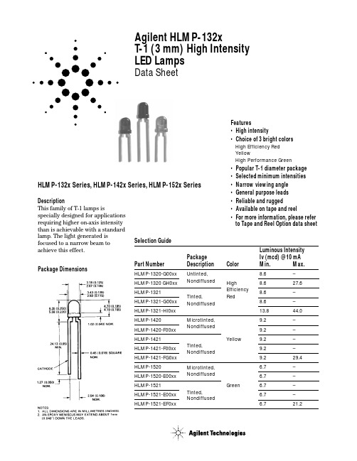
Agilent HLMP-132xT-1 (3 mm) High Intensity LED LampsData SheetFeatures•High intensity•Choice of 3 bright colors High Efficiency Red YellowHigh Performance Green•Popular T-1 diameter package •Selected minimum intensities •Narrow viewing angle •General purpose leads •Reliable and rugged•Available on tape and reel•For more information, please refer to Tape and Reel Option data sheetDescriptionThis family of T-1 lamps isspecially designed for applications requiring higher on-axis intensity than is achievable with a standard lamp. The light generated is focused to a narrow beam to achieve this effect.HLMP-132x Series, HLMP-142x Series, HLMP-152x SeriesPackage DimensionsSelection GuideLuminous Intensity Package Iv (mcd) @ 10 mA Part Number Description ColorMin.Max.HLMP-1320-G00xx Untinted,8.6–HLMP-1320 GH0xx Nondiffused High8.627.6HLMP-1321Tinted,Efficiency 8.6–HLMP-1321-G00xx Nondiffused Red8.6–HLMP-1321-HI0xx 13.844.0HLMP-1420Microtinted,9.2–HLMP-1420-F00xx Nondiffused9.2–HLMP-1421Yellow9.2–HLMP-1421-F00xx Tinted,9.2–HLMP-1421-FG0xx Nondiffused 9.229.4HLMP-1520Microtinted, 6.7–HLMP-1520-E00xx Nondiffused6.7–HLMP-1521Green6.7–HLMP-1521-E00xx Tinted,6.7–HLMP-1521-EF0xxNondiffused6.721.2Absolute Maximum Ratings at T A = 25°C ParameterRed Yellow Green Units Peak Forward Current 906090mA Average Forward Current [1]252025mA DC Current [2]302030mA Power Dissipation [3]13585135mW Reverse Voltage (I R = 100 µA)555V Transient Forward Current [4] (10 µsec Pulse)500500500mA LED Junction Temperature 110110110°C Operating Temperature Range -55 to +100-55 to +100-20 to +100°CStorage Temperature Range-55 to +100Notes:1. See Figure 5 (Red), 10 (Yellow), or 15 (Green) to establish pulsed operating conditions.2. For Red and Green series derate linearly from 50°C at 0.5 mA/°C. For Yellow series derate linearly from 50°C at 0.2 mA/°C.3. For Red and Green series derate power linearly from 25°C at 1.8 mW/°C. For Yellow series derate power linearly from 50°C at 1.6 mW/°C.4. The transient peak current is the maximum non-recurring peak current that can be applied to the device without damaging the LED die and wirebond.It is not recommended that the device be operated at peak currents beyond the peak forward current listed in the Absolute Maximum Ratings.Part Numbering System HLMP - 1 x xx - x x x xxMechanical Option 00: Bulk01: Tape & Reel, Crimped Leads 02: Tape & Reel, Straight LeadsA1: Right Angle Housing, Uneven Leads A2: Right Angle Housing, Even Leads Color Bin Options0: Full Color Bin DistributionMaximum Iv Bin Options 0: Open (no max. limit)Others: Please refer to the Iv Bin Table Minimum Iv Bin OptionsPlease refer to the Iv Bin TableLens Options20: Untinted or Microtinted, Non-diffused 21: Tinted, Non-diffused Color Options 3: GaP HER 4: GaP Yellow 5: GaP Green Package Options 1: T-1 (3 mm)Electrical Characteristics at T A = 25°CDeviceSymbol Description HLMP-Min.Typ.Max.Units Test ConditionsI V Luminous Intensity13208.630mcd I F = 10 mA13218.630(Figure 3)14209.215mcd I F = 10 mA14219.215(Figure 8)1520 6.722mcd I F = 10 mA1521 6.722(Figure 3)2q1/2Including Angle Between All45Deg.I F = 10 mA Half Luminous Intensity See Note 1Points(Figures 6, 11, 16, 21) l PEAK Peak Wavelength132x635nm Measurement142X583at Peak (Figure 1)152X565Dl1/2Spectral Line Halfwidth132x40nm142X36152X28l d Dominant Wavelength132x626nm See Note 2 (Figure 1)142X585152X569t s Speed of Response132x90ns142X90152X500C Capacitance132x11pF V F = 0; f = 1 MHz142X15152X18R q J-PIN Thermal Resistance All290°C/W Junction toCathode LeadV F Forward Voltage132x 1.9 2.4V I F = 10 mA142X 2.0 2.4152X 2.1 2.7V R Reverse Breakdown Voltage All 5.0V I R = 100 µAh V Luminous Efficacy132x145lumens See Note 3watt142X500152X595Notes:1. q1/2 is the off-axis angle at which the luminous intensity is half the axial luminous intensity.2. The dominant wavelength, l d, is derived from the CIE chromaticity diagram and represents the single wavelength which defines the color of thedevice.3. Radiant intensity, I e, in watts/steradian, may be found from the equation I e = l v/h v, where l v is the luminous intensity in candelas and h v is theluminous efficacy in lumens/watt.Figure 3. Relative luminous intensity vs. DC forward current.Figure 2. Forward current vs. forward voltage characteristics.Figure 4. Relative efficiency (luminous intensity per unit current) vs. peak LED current.Figure 5. Maximum tolerable peak current vs.pulse duration. (I DC MAX as per MAX ratings).Figure 6. Relative luminous intensity vs. angular displacement.Figure 1. Relative intensity vs. wavelength.T-1 High Efficiency Red Non-DiffusedFigure 10. Maximum tolerable peak current vs. pulse duration. (I DC MAX as per MAX ratings).Figure 11. Relative luminous intensity vs. angular displacement. Figure 8. Relative luminous intensity vs.forward current.Figure 7. Forward current vs. forward voltage characteristics.Figure 9. Relative efficiency (luminousintensity per unit current) vs. peak current.Figure 13. Relative luminous intensity vs.forward current.Figure 12. Forward current vs. forward voltage characteristics.Figure 14. Relative efficiency (luminous intensity per unit current) vs. peak LED current.Figure 15. Maximum tolerable peak current vs. pulse duration. (I DCMAX as per MAX ratings).Figure 16. Relative luminous intensity vs. angular displacement.Intensity Bin Limits Intensity Range (mcd)ColorBin Min.Max.E 7.612.0F 12.019.1G 19.130.7H 30.749.1I 49.178.5J 78.5125.7K 125.7201.1L201.1289.0GreenM 289.0417.0N 417.0680.0O 680.01100.0P 1100.01800.0Q 1800.02700.0R 2700.04300.0S 4300.06800.0T 6800.010800.0U 10800.016000.0V 16000.025000.0W25000.040000.0Maximum tolerance for each bin limit is ±18%.Intensity Bin Limits Intensity Range (mcd)ColorBin Min.Max.G 9.715.5H 15.524.8I 24.839.6J 39.663.4K 63.4101.5L 101.5162.4M 162.4234.6N 234.6340.0O340.0540.0RedP 540.0850.0Q 850.01200.0R 1200.01700.0S 1700.02400.0T 2400.03400.0U 3400.04900.0V 4900.07100.0W 7100.010200.0X 10200.014800.0Y 14800.021400.0Z 21400.030900.0F 10.316.6G 16.626.5H 26.542.3I 42.367.7J 67.7108.2K 108.2173.2L173.2250.0YellowM 250.0360.0N 360.0510.0O 510.0800.0P 800.01250.0Q 1250.01800.0R 1800.02900.0S 2900.04700.0T 4700.07200.0U 7200.011700.0V 11700.018000.0W18000.027000.0Color CategoriesLambda (nm)Color Category #Min.Max.6561.5564.55564.5567.5Green4567.5570.53570.5573.52573.5576.51582.0584.53584.5587.0Yellow2587.0589.54589.5592.05592.0593.0Maximum tolerance for each bin limit is ±0.5 nm.Mechanical Option MatrixMechanical Option Code Definition00Bulk Packaging, minimum increment 500 pcs/bag01Tape & Reel, crimped leads, minimum increment 1800 pcs/bag02Tape & Reel, straight leads, minimum increment 1800 pcs/bagA1Right Angle Housing, uneven leads, minimum increment 500 pcs/bagA2Right Angle Housing, even leads, minimum increment 500 pcs/bagNote:All categories are established for classification of products. Products may not be available in all categories. Please contact your local Agilent representative for further clarification/information.Precautions Lead Forming•The leads of an LED lamp may be preformed or cut to length prior to insertion and soldering into PC board.•If lead forming is required before soldering, care must be taken to avoid any excessive mechanical stress induced to LED package. Otherwise, cut the leads of LED to length after soldering process at roomtemperature. The solder joint formed will absorb the mechanical stress of the lead cutting from traveling to the LED chip die attach and wirebond.•It is recommended that tooling made to preciselyform and cut the leads to length rather than rely upon hand operation.Soldering Conditions•Care must be taken during PCB assembly and soldering process to prevent damage to LED component.•The closest LED is allowed to solder on board is 1.59mm below the body (encapsulant epoxy) for those parts without standoff.•Recommended soldering conditions:•Wave soldering parameter must be set andmaintained according to recommended temperature and dwell time in the solder wave. Customer isadvised to periodically check on the soldering profile to ensure the soldering profile used is always conforming to recommended soldering condition.•If necessary, use fixture to hold the LED component in proper orientation with respect to the PCB during soldering process.•Proper handling is imperative to avoid excessive thermal stresses to LED components when heated.Therefore, the soldered PCB must be allowed to cool to room temperature, 25°C, before handling.•Special attention must be given to board fabrication,solder masking, surface plating and lead holes size and component orientation to assure solderability.•Recommended PC board plated through hole sizes for LED component leads:Manual Solder Wave Soldering Dipping Pre-heat Temperature 105 °C Max.–Pre-heat Time 30 sec Max.–Peak Temperature 250 °C Max.260 °C Max.Dwell Time3 sec Max.5 sec Max.LED Component Plated Through Lead SizeDiagonal Hole Diameter 0.457 x 0.457 mm 0.646 mm 0.976 to 1.078 mm (0.018 x 0.018 inch)(0.025 inch)(0.038 to 0.042 inch)0.508 x 0.508 mm 0.718 mm 1.049 to 1.150 mm (0.020 x 0.020 inch)(0.028 inch)(0.041 to 0.045 inch)Note: Refer to application note AN1027 for more information on soldering LED components.Figure 17. Recommended wave soldering profile.BOTTOM SIDE OF PC BOARD TIME – SECONDST E M P E R A T U R E – °CTOP SIDE OF PC BOARDCONVEYOR SPEED = 1.83 M/MIN (6 FT/MIN)PREHEAT SETTING = 150°C (100°C PCB)SOLDER WAVE TEMPERATURE = 245°C AIR KNIFE AIR TEMPERATURE = 390°C AIR KNIFE DISTANCE = 1.91 mm (0.25 IN.)AIR KNIFE ANGLE = 40°SOLDER: SN63; FLUX: RMANOTE: ALLOW FOR BOARDS TO BESUFFICIENTL Y COOLED BEFORE EXERTING MECHANICAL FORCE./semiconductors For product information and a complete list of distributors, please go to our web site.For technical assistance call:Americas/Canada: +1 (800) 235-0312 or (916) 788-6763Europe: +49 (0) 6441 92460China: 10800 650 0017Hong Kong: (+65) 6756 2394India, Australia, New Zealand: (+65) 6755 1939 Japan: (+81 3) 3335-8152(Domestic/Interna-tional), or 0120-61-1280(Domestic Only) Korea: (+65) 6755 1989Singapore, Malaysia, Vietnam, Thailand, Philippines, Indonesia: (+65) 6755 2044 Taiwan: (+65) 6755 1843Data subject to change.Copyright © 2005 Agilent Technologies, Inc. Obsoletes 5989-2809ENNovember 12, 20055989-4253EN。
FANUC 30i31i32iSeries系统 B-64484CM-2_02加工中心操作说明书手册
FANUC Series 30+-MODEL B FANUC Series 31+-MODEL B FANUC Series 32+-MODEL B
加工中心系统
操作说明书
B-64484CM-2/02
· 本说明书的任何内容不得以任何方式复制。 · 所有参数指标和设计可随时修改,恕不另行通知。
本说明书中所载的产品,受到日本国《外汇和外国贸易法》的限制。从日本将 Series 30i-B、Series 31i-B5 出口到其他国家时,必须获得日本国政府的出口许可。本说明书 中的其他机型,同样受到出口限制。 另外,将该产品再出口到其他国家时,应获得再出口该产品的国家的政府许可。此外, 该产品可能还受到美国政府的再出口法的限制。 若要出口或者再出口此类产品,请向 FANUC 公司洽询。
s-2
B-64484CM-2/02
为了安全使用
注意 1 绝对/增量方式
如果用绝对值编写的程序在增量方式下执行,或者用增量值编写的程序在绝对方式下执行,会导致机床预想不 到的运转。 2 平面选择 对圆弧插补/螺旋插补/固定循环,如果指定的平面不正确,会导致机床预想不到的运转。详情请参阅各自的功 能描述。 3 扭矩极限跳转 在试图进行扭矩极限跳转之前,务须将扭矩极限设为有效。 如果在扭矩极限失效的状态下指定扭矩极限跳转,将执行移动指令而不产生跳转动作。 4 可编程镜像 注意:当可编程镜像被设为有效时,之后的程序动作将会发生很大的变化。 5 补偿功能 如果在补偿功能方式下指定机床坐标系的指令或与参考点返回相关的指令,则会暂时取消补偿,从而导致机床 预想不到的运转。 因此,在发出上述任何指令之前,先取消补偿功能方式。
Manual Motor Starter MS132 说明书

Manual motor starter MS132Description- Overload protection – trip class 10- Phase loss sensitivity- Disconnect function- Temperature compensation from -25 … +60 °C - Adjustable current setting for overload protection - Suitable for three- and single-phase application - Trip-free mechanism- Trip indication- Clear switch position indication ON/OFF/TRIP- Lockable handle Ordering detailsMS132 screw terminalManual motor starters are electrome-chanical protection devices for the maincircuit. They are used mainly to switchmotors manually ON/OFF and protectthem fuse less against short-circuit,overload and phase failures.Fuse less protection with a manual motorstarter saves costs, space and ensuresa quick reaction under short-circuitcondition, by switching off the motorwithin milliseconds. Fuse less startercombinations are setup together withcontactors.Setting range Type Trip Order code Packing Weight[A] class unit [Pcs] [g]0.10 ... 0.16 MS132-0.16 10A 1SAM350000R1001 1 2150.16 ... 0.25 MS132-0.25 10 1SAM350000R1002 1 2150.25 ... 0.40 MS132-0.4 10 1SAM350000R1003 1 2150.40 ... 0.63 MS132-0.63 10 1SAM350000R1004 1 2150.63 ... 1.00 MS132-1.0 10 1SAM350000R1005 1 2151.00 ... 1.60 MS132-1.6 10 1SAM350000R1006 1 2651.60 ...2.50 MS132-2.5 10 1SAM350000R1007 1 2652.50 ... 4.00 MS132-4.0 10 1SAM350000R1008 1 2654.00 ... 6.30 MS132-6.3 10 1SAM350000R1009 1 2656.30 ... 10.00 MS132-10 10 1SAM350000R1010 1 2658.00 ... 12.00 MS132-12 10 1SAM350000R1012 1 31010.00 ... 16.00 MS132-16 10 1SAM350000R1011 1 31016.00 ... 20.00 MS132-20 10 1SAM350000R1013 1 31020.00 ... 25.00 MS132-25 10 1SAM350000R1014 1 31025.00 ... 32.00 MS132-32 10 1SAM350000R1015 1 310Note: MS132 with pre-assembled auxiliary contact HKF1-11, please order as follow 1SAM350005Rxxxx2 2CDC131021D0201The manual motor starters protect the load and the installa-tion against short-circuit and overload. They are three pole protection devices with thermal tripping elements for overload protection and electro-magnetic tripping elements for short-circuit protection. Furthermore, they provide a disconnect function for safely isolation of the installation and the supply and can be used for the manual switching of loads.Operation modeSingle-phase operationThree-phase operationThe manual motor starters have a setting scale in Amperes, which allows the direct adjusting of the device without any additional calculation. In compliance with international and national standards, the setting current is the rated current of the motor and not the tripping current (no tripping at 1.05 x I, tripping at 1.2 x I; I = setting current).Type Lower value Upper value Resistance Power loss per Phase [W] at setting range setting range per phase Lower value of Upper value of[A] [A] [W ] setting range setting range MS132-0.16 0.10 0.16 66.00 0.7 1.7MS132-0.25 0.16 0.25 25.50 0.7 1.7MS132-0.4 0.25 0.40 10.38 0.7 1.7MS132-0.63 0.40 0.63 4.36 0.7 1.7MS132-1.0 0.63 1.001.605 0.7 1.7MS132-1.6 1.00 1.60 0.648 0.7 1.7MS132-2.5 1.60 2.50 0.272 0.7 1.7MS132-4.0 2.50 4.00 0.106 0.7 1.7MS132-6.3 4.00 6.30 0.046 0.7 1.7MS132-10 6.30 10.00.0240.9 2.4MS132-12 8.00 12.0 0.016 1.0 2.3MS132-16 10.0 16.0 0.011 1.1 2.8MS132-20 16.0 20.0 0.0057 1.5 2.3MS132-25 20.0 25.0 0.0045 1.8 2.8MS132-3225.032.00.00301.93.1Resistance and power losses per phaseConnections2CDC131021D0201 3EGLGOST-FGOST-RMS132 ≤ 10 A + screw fixing kit MS132 > 10 A + screw fixing kitMS132 ≤ 10 AMS132 > 10 AWiring diagramApprovals cULus UL 508 ABSMarkingsCEKPData at T= 40 °C and at rated values, if nothing else indicatedAType MS132Technical data TerminalsMain circuit 1L1-3L3-5L52T1-4T2-6T3acc. to IEC/EN 60947-1 a.c. 690 VRated operational voltage Ued.c. -Rated operational current Isee separate tablee/ see …Rated Operational Current“Rated current InConventional free-air thermal current IthSetting range - thermal overload protection see ordering dataRated instantaneous short-circuit current setting Isee separate tableisee separate tableRated service short-circuit breaking capacity IcsRated ultimate short-circuit breaking capacity Isee separate tablecuTrip class acc. to IEC/EN 60947-4-1 see ordering dataRated frequency acc. to IEC/EN 60947-1 50 / 60 HzNumber of poles 3Resistence per phase see separate tablePower loss per phase lower value of setting range see separate tableupper value of setting range see separate tableIsolation dataacc. to IEC/EN 60947-1 6 kVRated impulse withstand voltage Uimpacc. to IEC/EN 60947-1 690 VRated insulation voltage UiPollution degree acc. to IEC/EN 60664 3Electrical connectionMS132 ≤ 10AConnecting capacity solid 1/2 x 1 ... 4 mm2flexible with ferrule 1/2 x 0.75 ... 2.5 mm2flexible with ferrule isolated1/2 x 0.75 ... 2.5 mm2flexible without ferrule 1/2 x 0.75 ... 2.5 mm2Stripping length 9 mmTightening torque 0.8 ... 1.2 NmConnection screw M3.5 (Pozidrive 2)MS132-12, -16Connecting capacity solid 1/2 x 1 ... 4 mm2flexible with ferrule 1/2 x 0.75 ... 2.5 mm2flexible with ferrule isolated1/2 x 0.75 ... 2.5 mm2flexible without ferrule 1/2 x 0.75 ... 2.5 mm2Stripping length 10 mmTightening torque 1.5 NmConnection screw M4 (Pozidrive 2)MS132-20, -25, -32Connecting capacity solid 1/2 x 2.5 ... 6 mm2flexible with ferrule 1/2 x 1 ... 6 mm2flexible with ferrule isolated1/2 x 1 ... 6 mm2flexible without ferrule 1/2 x 2.5 ... 6 mm2Stripping length 10 mmTightening torque 2 NmConnection screw M4 (Pozidrive 2)4 2CDC131021D0201General DataMechniacl durability 105Electrical durability 5 x 10⁴Duty time 100%Dimensions (W x H x D) see dimension drawingWeight see ordering dataMounting DIN-rail (EN 60715)Mounting positions optional for single mounting(position 1-6)Group Mounting on requestMinimum distance to other units same type horizontal 0 mmvertical 150 mmMinimum distance to electrical conductive wall (earthed) horizontal - up to 400 V 0 mmhorizontal - up to 690 V > 1.5 mmvertical 75 mmDegree of protection acc. to IEC/EN 60947-1 enclosure / terminals IP20Utilization Category acc. to IEC/EN 60947-2 AAltitude up to 2000 mEnvironmental dataAmbient air temperature rangeOperation open - compensated without derating-25 °C ... +60 °Copen -25 °C ... +70 °CStorage -50 °C ... +80 °CTemperature compensation continuousVibration (sinusoidal) acc. to IEC/EN 60068-2-6 (Fc) 5 g / 3 - 150 HzShock (half-sine) acc. to IEC/EN 60068-2-27 (Ea) 25 g / 11 msStandards / DirectivesStandard IEC/EN 60947–2, ICE/EN 60947-4-1,IEC/EN 60947-1, UL 508;CSA 22.2 No. 14Low Voltage Directive 2006/95/ECEMC Directive 2004/108/ECRoHS Directive 2002/95/ECElectromagnetic compatibilitynot applicableApprovals, markingsApprovals see page 3Markings see page 3UL/CSAMax. operational voltage 600 VManual Motor Controller ratings see separate tableMotor ratingsHorse power see separate tableFull load amps (FLA) see separate tableLocked rotor amps (LRA) see separate tableShort-Circuit Protective devices see separate table2CDC131021D020156 2CDC131021D0201Type Rated instantaneousRated current l n / Conventionalshort-circuit current setting l i [A] free-air thermal current l th [A] MS132-0.16 1.25 … 1.87 0.16 MS132-0.25 1.95 … 2.92 0.25 MS132-0.4 3.12 … 4.68 0.40 MS132-0.63 4.91 … 7.37 0.63 MS132-1.0 9.20 … 13.8 1.00 MS132-1.6 14.7 … 22.1 1.60 MS132-2.5 23.0 … 34.5 2.50 MS132-4.0 40.0 … 60.0 4.00 MS132-6.3 63.0 … 94.5 6.30 MS132-10 120 … 180 10.0MS132-12 144 … 216 12.0 MS132-16 192 … 288 16.0 MS132-20 240 … 360 20.0 MS132-25 300 … 450 25.0 MS132-32384 (576)32.0Type 230 V AC 400 V AC 690 V ACI CS [kA] I CU [kA] gG [A] I CS [kA] I CU [kA] gG [A] I CS [kA] I CU [kA] gG [A]MS132-0.16 100 100 ° 100 100 ° 100 100 °MS132-0.25 100 100 ° 100 100 ° 100 100 °MS132-0.4 100 100 ° 100 100 ° 100 100 °MS132-0.63 100 100 ° 100 100 ° 100 100 °MS132-1.0 100 100 ° 100 100 ° 100 100 °MS132-1.6 100 100 ° 100 100 ° 100 100 °MS132-2.5 100 100 ° 100 100 ° 100 100 °MS132-4.0 100 100 ° 100 100 ° 3 3 on request MS132-6.3 100 100 ° 100 100 ° 3 3 on request MS132-10 100 100 ° 100 100 ° 3 3 on request MS132-12 100 100 ° 100 100 ° 3 3 on request MS132-16 100 100 ° 100 100 ° 3 3 on request MS132-20 100 100 ° 100 100 ° 3 3 on request MS132-25 50 50 100 50 50 100 3 3 on request MS132-322550125255012533on requestShort-Circuit protectionl CS = Rated service short-circuit breakingcapacityl CU = Rated ultimate short-circuit breaking capacityo = No back-up fuse required, because short-circut proof up to 100 kATechnical data Electrical connection MS132 ≤ 10AConnecting capacity solid 1/2 x AWG16 ... AWG12 stranded1/2 x AWG16 ... AWG12flexible without ferrule 1/2 x AWG16 ... AWG12 Stripping length 9 mm Tightening torque 10 - 12 lb-in Connection screw M3.5 (Pozidrive 2) MS132-12, -16Connecting capacity solid 1/2 x AWG16 ... AWG12 stranded1/2 x AWG16 ... AWG12flexible without ferrule 1/2 x AWG16 ... AWG12 Stripping length 10 mm Tightening torque 14 lb-inConnection screwM4 (Pozidrive 2 / 6.5 mm)MS132-20, -25, -32 Connecting capacity stranded1/2 x AWG12 ... AWG8flexible without ferrule 1/2 x AWG12 ... AWG8 Stripping length 10 mm Tightening torque 18 lb-InConnection screwM4 (Pozidrive 2)UL / CSA ratingsType Motor rating, single phase220 - 240 V AC 440 - 480 V AChp FLA LRA hp FLA LRAMS132-0.16 - 0.16 0.96 - 0.16 0.96MS132-0.25 - 0.25 1.5 - 0.25 1.5MS132-0.4 - 0.4 2.4 - 0.4 2.4MS132-0.63 - 0.63 3.78 - 0.63 3.78MS132-1.0 - 1 6 - 1 6MS132-1.6 1/10 1.6 9.6 - 1.6 9.6MS132-2.5 1/6 2.5 15 1/2 2.5 15MS132-4.0 1/3 4 24 1/2 4 24MS132-6.3 1/2 6.3 37.8 1 6.3 37.8MS132-10 1-1/2 10 60 3 8.5 46MS132-12 2 12 72 3 8.5 64MS132-16 2 12 72 5 14 81MS132-20 3 17 92 5 14 81MS132-25 3 17 127 7-1/2 21 116MS132-32 5 28 162 10 26 145Type Motor rating, three phase110 - 120 V AC 220 - 240 V AC 440 - 480 V AC 500 - 600 V AChp FLA LRA hp FLA LRA hp FLA LRA hp FLA LRAMS132-0.16 - 0.16 0.96 - 0.16 0.96 - 0.16 0.96 - 0.16 0.96MS132-0.25 - 0.25 1.5 - 0.25 1.5 - 0.25 1.5 - 0.25 1.5MS132-0.4 - 0.4 2.4 - 0.4 2.4 - 0.4 2.4 - 0.4 2.4MS132-0.63 - 0.63 3.78 - 0.63 3.78 - 0.63 3.78 - 0.63 3.78MS132-1.0 - 1 6 - 1 6 - 1 6 1/2 1 6MS132-1.6 - 1.6 9.6 - 1.6 9.6 3/4 1.6 9.6 3/4 1.6 9.6MS132-2.5 - 2.5 15 1/2 2.5 15 1 2.5 15 1-1/2 2.5 15MS132-4.0 - 4 24 1 4 24 2 4 24 3 3.9 26MS132-6.3 1/2 6.3 37.8 1-1/2 6.3 37.8 3 4.8 32 5 6.1 37MS132-10 3/4 10 60 3 9.6 64 5 7.6 46 7-1/2 9 51MS132-12 1-1/2 12 72 3 9.6 64 7-1/2 11 64 10 11 65MS132-16 2 16 84 5 15.2 92 10 14 81 10 11 65MS132-20 3 19.2 128 5 15.2 92 10 14 81 15 17 93MS132-25 3 19.2 128 7-1/2 22 127 15 21 116 20 22 116MS132-32 5 30.4 184 10 28 162 20 27 145 25 27 146Type UL 508 — Manual Motor ControllerMax. Circuit Max. Fuse for Motor D isconnect for Group Installation for Tap ConductorBreaker per type K5 o. RK5 Max. Short Circuit Max. Short Circuit Max. Short CircuitUL/NEC per UL/NEC Current [kA] Current [kA] Current [kA]480 V / 600 V [A] 480 V / 600 V [A] 480 V 600 V 480 V 600 V 480 V 600 VMS132-0.16 250 250 30 18 30 - 30 -MS132-0.25 250 250 30 18 30 - 30 -MS132-0.4 250 250 30 18 30 - 30 -MS132-0.63 250 250 30 18 30 - 30 -MS132-1.0 250 250 30 18 30 - 30 -MS132-1.6 250 250 30 18 30 - 30 -MS132-2.5 250 250 30 18 30 - 30 -MS132-4.0 250 250 30 18 30 - 30 -MS132-6.3 250 250 30 18 30 - 30 -MS132-10 250 250 30 18 30 - 30 -MS132-12 250 250 30 18 30 - 30 -MS132-16 250 250 30 18 30 - 30 -MS132-20 250 250 30 18 30 - 30 -MS132-25 250 250 30 18 30 - 30 -MS132-32 250 250 30 18 30 - 30 -2CDC131021D02017ABB STOTZ-KONTAKT GmbH P . O. Box 10 16 8069006 Heidelberg, Germany Phone: +49 (0) 6221 7 01-0Fax: +49 (0) 6221 7 01-13 25E-Mail:*****************.comYou can find the address of your local sales organisation on the ABB home page/contacts -> Low Voltage productsContact usNote:We reserve the right to make technical changes or modify the contents of this document without prior notice. With regard to purchase orders, the agreed particulars shall prevail. ABB AG does not accept any responsibility whatsoever for potential errors or possible lack of information in this document.We reserve all rights in this document and in the subject matter and illustrations contained therein. Any reproduction, disclosure to third parties or utilization of its contents – in whole or in parts – is forbidden without prior written consent of ABB AG. Copyright© 2010 ABB All rights reservedO r d e r N u m b e r 2C D C 131 021 D 0201 P r i n t e d i n G e r m a n y (04.10)。
QuickSetter+平衡阀与流量计132AFC系列技术参数说明书

QuickSetter +™balancing valve with flow meter132AFC seriesTechnical specifications Materials Valve Body: DZR low-lead brassBall:stainless steelBall control stem: brass, chrome platedBall seal seat:PTFE Control stem guide: PSUSeals:peroxide-cured EPDMFlow meterBody and headwork: DZR low-lead brassBypass valve stem: stainless steel Springs: stainless steelSeals:peroxide-cured EPDMFlow meter float and indicator cover:PSUNSF/ANSI/CAN 372, Drinking Water System Components-Lead Content Reduction of Lead in Drinking Water Act, California Health and Safety Code 116875 S.3874, Reduction in Drinking Water Act, certified by ICC-ES, file PMG-1360.Performance Suitable Fluids:water, glycol solutionsMax. percentage of glycol: 50%Max. working pressure:150 psi (10 bar)Working temperature range:14°F - 230°F (-10°C –110°C)Flow rate range unit of measurement:½ - 1 ¾ gpm 2 - 7 gpmAccuracy: ±10%Control stem angle of rotation: 90°Control stem adjustment wrench: 9 mm Outlet temperature gauge (optional): 2" diameterDual-scale 30°F - 210°F (0°C –100°C)FunctionThe QuickSetter+™ manual balancing valve contains a built-in flow meter and sight gauge, negating the need for differential pressure gauges and reference charts. Circuit balancing is fast, easy and accurate. Constructed of DZR low-lead brass, QuickSetter+ is ideally suited for use in plumbing applications such as hot water recirculation systems. The built-in check valve protects against circuit thermo-siphoning. The outlet temperature gauge (optional) verifies the fluid temperature in the circuit. The flow meter sight gauge is dry (not exposed to the fluid) thus eliminating the possibility of gauge clouding/scaling over time. Peroxide-cured EPDM seals provide chlorine and chloramine resistance and long operating life. The QuickSetter+ can also be used in heating systems.The valve complies with NSF/ANSI/CAN 372, low lead, as certified by ICC-ES.Caleffi code 290030 full-port ball valve is designed for isolating the QuickSetter+ 132AFC series that has 1" metric "G " thread union connections. The isolation valve installs in between the valve body and the tailpiece fitting assembly. Male x Female configuration and bi-directional full ball valve flow capacity provides flexibility for using one, two or three isolation valves for the primary functioning valve. An optional stem extension is also available for those projects that require pipe insulation.Product range132AFC series Balancing valve with flow meter, includes check valve and optional dual-scal outlet temperature gauge..................sizes ½”, ¾”, 1”with sweat, press, PEX crimp, PEX expansion union connections Replaces 01283/21 N ACertifications1.NSF/ANSI/CAN 372, Drinking Water SystemComponents-Lead Content Reduction of Lead in Drinking Water Act, California Health and Safety Code 116875 S.3874, Reduction in Drinking Water Act, Vermont Act 193 - The Lead in PlumbingSupplies Law and Maryland’s Lead Free Law HB.372,certified by ICC-ES, file PMG-1360.2.PEX crimp fittings certified to ASTM F 1807.3.PEX expansion fittings certified to ASTM F 1960.ConnectionsMain connections:½”, ¾”, 1” sweat union ½”, ¾”, 1” PEX crimp union ½”, ¾”, 1” PEX expansion union½”, ¾”, 1" press unionLay length (press connection):size ½ inch without gauge: 7 5/16" size ½ inch with gauge: 10 1/8"size ¾ inch without gauge: 7 5/16"size ¾ inch with gauge: 10 1/8"size 1 inch without gauge: 8 ½"size 1 inch with gauge: 10 ¾"Flow rate rangesCodeUnionConnectionsFlow rate(gpm)FullyopenCv132434AFC½" PEX crimp0.5 - 1.75 1.0 132432AFC½" PEX expansion0.5 - 1.75 1.0 132436AFC½" press0.5 - 1.75 1.0 132439AFC½" sweat0.5 - 1.75 1.0 132534AFC¾" PEX crimp0.5 - 1.75 1.0 132532AFC¾" PEX expansion0.5 - 1.75 1.0 132536AFC¾" press0.5 - 1.75 1.0 132539AFC¾" sweat0.5 - 1.75 1.0 132634AFC1" PEX crimp0.5 - 1.75 1.0 132632AFC1" PEX expansion0.5 - 1.75 1.0 132636AFC1" press0.5 - 1.75 1.0 132639AFC1" sweat0.5 - 1.75 1.0 132454AFC½" PEX crimp 2.0 - 7.0 6.3 132452AFC½" PEX expansion 2.0 - 7.0 6.3 132456AFC½" press 2.0 - 7.0 6.3 132459AFC½" sweat 2.0 - 7.0 6.3 132554AFC¾" PEX crimp 2.0 - 7.0 6.3 132552AFC¾" PEX expansion 2.0 - 7.0 6.3 132556AFC¾" press 2.0 - 7.0 6.3 132559AFC¾" sweat 2.0 - 7.0 6.3 132654AFC1" PEX crimp 2.0 - 7.0 6.3 132652AFC1" PEX expansion 2.0 - 7.0 6.3 132656AFC1" press 2.0 - 7.0 6.3 132659AFC1" sweat 2.0 - 7.06.3With temperature gauge.Without temperature gauge.Dimensions*(without temperature gauge / with temperature gauge)Code (w/o gauge)Code (w/ gauge)A B (w/o gauge)C(w/ gauge)Wt (lb)*132434AFC 132435AFC 1/2" PEX crimp 9"10 5/16" 1.8/2.2132432AFC 132433AFC 1/2" PEX expansion 9 1/8"10 7/16" 1.8/2.2132439AFC 132438AFC 1/2" sweat 8 3/8"9 11/16" 2.0/2.4132534AFC 132535AFC 3/4" PEX crimp 10 1/8"12 5/8" 2.0/2.4132532AFC 132533AFC 3/4" PEX expansion 10 7/8"13 3/8" 2.0/2.4132539AFC 132538AFC 3/4" sweat 8 7/16"9 13/16" 1.8/2.2132634AFC 132635AFC 1" PEX crimp 8 11/16"10 1/4" 2.2/2.6132632AFC 132633AFC 1" PEX expansion 9 11/16"11 1/4" 2.2/2.6132639AFC 132638AFC 1" sweat 8 9/16"10 1/8" 2.4/2.8132454AFC 132455AFC 1/2" PEX crimp 9"10 5/16" 1.8/2.2132452AFC 132453AFC 1/2" PEX expansion 9 1/8"10 7/16" 1.8/2.2132459AFC 132458AFC 1/2" sweat 8 3/8"9 11/16" 2.0/2.4132554AFC 132555AFC 3/4" PEX crimp 10 1/8"12 5/8" 2.0/2.4132552AFC 132553AFC 3/4" PEX expansion 10 7/8"13 3/8" 2.0/2.4132559AFC 132558AFC 3/4" sweat 8 7/16"9 13/16" 1.8/2.2132654AFC 132655AFC 1" PEX crimp 8 11/16"10 1/4" 2.2/2.6132652AFC 132653AFC 1" PEX expansion 9 11/16"11 1/4" 2.2/2.6132659AFC132658AFC1" sweat8 9/16"10 1/8"2.4/2.8Code (w/o gauge)Code (w/ gauge)A B (w/o gauge)C(w/ gauge)Wt (lb)*132436AFC 132437AFC 1/2" press 9 3/8"11 5/8" 1.8/2.2132456AFC 132457AFC 1/2" press 9 3/8"11 5/8" 1.8/2.2132536AFC 132537AFC 3/4" press 9 7/8"12 1/8" 1.8/2.2132556AFC 132557AFC 3/4" press 9 7/8"12 1/8" 1.8/2.2132636AFC 132637AFC 1" press 10 1/4"12 1/2" 2.2/2.6132656AFC132657AFC1" press10 1/4"12 1/2"2.2/2.6*(without temperature gauge / with temperature gauge)Lay length (press connection):size ½ inch without gauge: 7 5/16"size ½ inch with gauge: 10 1/8"size ¾ inch without gauge: 7 5/16"size ¾ inch with gauge: 10 1/8"size 1 inch without gauge: 8 ½"size 1 inch with gauge: 10 ¾"Flow rate adjustmentThe flow rate is adjusted as follows:to the axis control stem is turned fully counter-clockwise axis of the valve), the132 seriesPump10DA. With the aid of the flow rate indicator (1), mark the desired flow rate.C. W hile holding the bypass valve open, use a wrench to turn the valve control stem (4) to adjust the flow rate slowly. The resulting flow rate is indicated by the metal ball (5) that slides up and down inside a transparent channel (6) marked by a graduated scale in gpm.in event it is damaged and inoperable. Order code F19346.A B Completely closed Completely open Install the balancing valve in a location that ensures free access to the flow meter shutoff valve, control stem and flow rate indicator. To ensure accurate flow measurement, straight sections of pipe installed as shown is recommended.B. U se the operating ring (2) to open the bypass valve slowly. This allows fluid to flow through the flow meter (3). The bypass valve is automatically closed under normal operating conditions.A BCBalancing made fast, easy, and accurate with QuickSetter+Hot water recirculation systems are designed to minimize wait time for hot water to arrive when a fixture is opened. Systems left unbalanced or improperly balanced result in wasted water down the drain, a costly and environmentally unfriendly situation - not to mention the undesired annoyance placed on building occupants. The QuickSetter+ takes the guess work and labor out of balancing. With the valve's exclusively designed venturi mechanism, the installer simply pulls the flow indicator by-pass pin, adjusts the flow to the desired flow rate while viewing the built-in sight gauge, and releases the pin. Easy, accurate balancing in seconds. No instruments or reference graphs are needed.Hot water recirculation Unbalanced exampleBalanced exampleReplacement body.Select fittings from the Catalog Product Guide, fitting section.Code DescriptionLbs 132637 0.5 to 1.75 gpm 1.0 1326572.0 to 7.0 gpm1.0QuickSetter Insulation sleeve for valve and fitting on each end.Code Description LbsF0000926 For models with temperature gauge 0.1112001For models without temperature gauge 0.1Replacement flow meter.Code Description LbsF0000940 0.5 to 1.75 gpm 0.2F0000941 2.0 to 7.0 gpm 0.2 F19346 Replacement by-pass stem with operating ring 0.2Isolation ball valve.Low lead Male x Female union fits 1" valves between body and tailpiece. See below.Code Description Lbs290030 Isolation ball valve 1" M x 1" F union 1.0NA10815 Stem extension for 2900300.2Isolation ball valves, installed on QuickSetter+ without optional temperature gauge.For more information, consult Technical Brochure 1397-22 NA at 132 seriesBalancing valve with flow meter. Sweat, Press. PEX crimp and PEX expansion union connections ½”, ¾", 1". PEX crimp fittings must comply with ASTM F 1807. PEX expansion fittings must comply with ASTM F 1960. DZR low-lead brass body (<0.25% Lead content) certified by ICC-ES file PMG-1360. Stainless steel ball. Chrome-plated brass ball control stem. PTFE ball seal seat. PSU control stem guide. DZR low-lead brass flow meter body and headwork. Stainless steel flow meter bypass valve stem. Stainless steel flow meter springs. PSU flow meter float and indicator cover. Peroxide-cured EPDM seals. Provided with inlet flow check valve. Water and glycol solutions. Maximum percentage of glycol 50%. Maximum working pressure 150 psi (10 bar). Working temperature range 14 to 230 degrees F (-10 to 110 degrees C). Flow rate range unit of measurement gallons per minute (gpm). Accuracy ± 10%. Control stem angleof rotation 90°. Provide with optional mixed outlet dual-scale temperature gauge, 30 to 210 degree F scale and 0 to 100 degree C scale , 2 inch diameter. Provide with optional inlet and outlet isolation ball valves, code 290030, separately sourced, field installed.SPECIFICATION SUMMARYWe reserve the right to change our products and their relevant technical data, contained in this publication, at any time and without prior notice.Caleffi North America, Inc.3883 W. Milwaukee Road Milwaukee, WI 53208Tel: 414-238-2360 · Fax: 414-238-2366*****************·© Copyright 2022 Caleffi North America, Inc.Find us inhttps:///specpointfind BIM Revit files and system templates athttps:///en-us。
爱立智麦勒尔ZB系列电机保护开关产品说明书

Eaton 278442Eaton Moeller® series ZB Motorschutzrelais, ZB32, Ir= 0,1 - 0,16A, 1 S, 1 Ö, Direktmontage, IP20Allgemeine spezifikationEaton Moeller® series ZB Thermaloverload relay278442401508278442396 mm67 mm45 mm0.141 kgUL File No.: E29184CSA Class No.: 3211-03CSA-C22.2 No. 60947-4-1-14 IEC/EN 60947VDE 0660IEC/EN 60947-4-1ULUL Category Control No.: NKCR CSA File No.: 012528CECSAUL 60947-4-1Überlastrelais thermisch ZB32-0,16Produktname KatalognummerEANProdukt Länge/Tiefe Produkthöhe Produktbreite Produktgewicht Zertifikat(e)ProdukttypModellcodePhasenausfallempfindlichkeit (gemäß IEC/EN 60947, VDE 0660 Teil 102)Reset-Taste Hand/Auto Freiauslösung Test/Aus-Taste-25 °C55 °C25 °C40 °C CLASS 10 A Feuchte Wärme, konstant, nach IEC 60068-2-78 Feuchte Wärme, zyklisch, nach IEC 60068-2-30IP20ZB32Direct attachment Direktanbau0.1 A0.16 AIII3Finger- und handrückensicher, Berührungsschutz bei senkrechter Betätigung von vorne (EN 50274)MerkmaleUmgebungsbetriebstemperatur – min Umgebungsbetriebstemperatur – max Umgebungsbetriebstemperatur (gekapselt) – min Umgebungsbetriebstemperatur (gekapselt) – max Klasse KlimafestigkeitSchutzart Rahmengr.Montageart Überlastauslösestromeinstellung - min Überlastauslösestromeinstellung - max Überspannungskategorie Verschmutzungsgrad Produktkategorie SchutzZubehörMotorschutzrelais ZB bis 150 A6000 V AC4000 V (Hilfs- und Steuerkreise)10 g, Mechanisch, Sinusförmig, Schockdauer 10 ms Nebenstromkreise, (UL/CSA)≤ 0,25 %/K, Restfehler für T > 40° Kontinuierlich 2 x (0,75 - 2,5) mm², Steuerstromleitungen2 x (1 - 4) mm², Hauptleiter1 x (1 - 4) mm², Hauptleiter1 x (0,75 - 2,5) mm², Steuerstromleitungen1 x (0,75 - 4) mm², Steuerstromleitungen2 x (0,75 - 4) mm², Steuerstromleitungen1 x (1 - 6) mm², Hauptleiter2 x (1 - 6) mm², Hauptleiter2 x (18 - 14), Steuerstromleitungen18 - 8, Hauptleiter10 mm8 mmM3,5, Anschlussschraube, HilfsleiterM4, Anschlussschraube2, Anschlussschraube, Pozidriv-Schraubendreher1 x 6 mm, Anschlussschraube, Schlitzschraubendreher1,2 Nm, Schraubklemmen, Steuerstromleitungen1.8 Nm, Schraubklemmen, Hauptleiter6 A 1.5 A 1.5 A 0.9 A 100 kA, Sicherung, SCCR (UL/CSA)1 A, Klasse J/CC, max. Sicherung, SCCR (UL/CSA)0,5 A gG/gL, Sicherung, Zuordnungsart "2"Max. 6 A gG/gL, Sicherung, Ohne Verschweißen, Hilfs- und Steuerkreise25 A gG/gL, Sicherung, Zuordnungsart "1"Bemessungsstoßspannungsfestigkeit (Uimp)Schockfestigkeit Geeignet für Temperaturkompensation Anschlusskapazität (freindrähtig mit Aderendhülse) Anschlusskapazität (fest)Anschlusskapazität (ein-/mehrdrähtig AWG) Abisolierlänge (Hauptleiter)Abisolierlänge (Hilfsleiter)Schr-GröSchraubendrehergrößeAnzugsdrehmomentKonventioneller thermischer Strom lth der Hilfskontakte (1-polig, offen)Bemessungsbetriebsstrom (le) bei AC-15, 120 V Bemessungsbetriebsstrom (le) bei AC-15, 220 V, 230 V, 240 V Bemessungsbetriebsstrom (le) bei AC-15, 380 V, 400 V, 415 V Bemessungskurzschlussstrom (hoher Fehlerstrom bei 600 V) Bemessungsdaten Kurzschlussschutz0.4 A0.2 A0.9 A0.75 A690 V440 V, Zwischen Hilfskontakten und Hauptkontakten, Entspricht EN 61140440 V AC, zwischen den Hauptstrombahnen, Entspricht EN 61140240 V AC, Zwischen Hilfskontakten, Entspricht EN 61140B300 bei gegenüberliegender Polarität, AC-betätigt (UL/CSA) B600 bei gegenüberliegender Polarität, AC-betätigt (UL/CSA) R300, DC-betätigt (UL/CSA)600 VAC600 VAC 011115.4 W0 W1.8 W0.16 A0 WAnforderungen der Produktnorm sind erfüllt.Anforderungen der Produktnorm sind erfüllt.Anforderungen der Produktnorm sind erfüllt.Anforderungen der Produktnorm sind erfüllt.Anforderungen der Produktnorm sind erfüllt.Unzutreffend, da die gesamten Schaltgeräte überprüft werdenBemessungsbetriebsstrom (le) bei DC-13, 110 VBemessungsbetriebsstrom (le) bei DC-13, 220 V, 230 V Bemess.betriebsstrom (le) bei DC-13, 24 V Bemessungsbetriebsstrom (le) bei DC-13, 60 V Bemessungsbetriebsspannung (Ue) - maxSichere TrngSchaltvermögen (Hilfskontakte, Steuerzyklus) Nennspannung - maxNennspannung - max Anzahl der Hilfskontakte (Wechsler)Anzahl der Hilfskontakte (Öffner)Anzahl Hilfskontakte (Schließer)Anzahl der Kontakte (Öffner)Anzahl der Kontakte (Schließer)Geräteverlustleistung, stromabhängig pvid Verlustleistungskapazität PdissVerlustleistung pro Pol, stromabhängig, Pvid Bemessungsbetriebsstrom zur Verlustleistungsangabe (In) Statische Verlustleistung, stromunabhängig PVS10.2.2 Korrosionsbeständigkeit10.2.3.1 Wärmebeständigkeit von Umhüllung10.2.3.2 Widerstandsfähigkeit Isolierstoffe gewöhnliche Wärme 10.2.3.3 Widerst. Isolierstoffe abnorm. Wärme/Feuer durch int. elektr. Auswirk.10.2.4 Beständigkeit gegen UV-Strahlung10.2.5 Hebenmüssen.Unzutreffend, da die gesamten Schaltgeräte überprüft werdenmüssen.Anforderungen der Produktnorm sind erfüllt.Unzutreffend, da die gesamten Schaltgeräte überprüft werden müssen.Anforderungen der Produktnorm sind erfüllt.Unzutreffend, da die gesamten Schaltgeräte überprüft werden müssen.Unzutreffend, da die gesamten Schaltgeräte überprüft werden müssen.Liegt in der Verantwortung des Schaltanlagenbauers.Liegt in der Verantwortung des Schaltanlagenbauers.Liegt in der Verantwortung des Schaltanlagenbauers.Liegt in der Verantwortung des Schaltanlagenbauers.Liegt in der Verantwortung des Schaltanlagenbauers.Die Erwärmungsberechnung liegt in der Verantwortung des Schaltanlagenbauers. Eaton stellt Verlustleistungsdaten der Geräte bereit.Liegt in der Verantwortung des Schaltanlagenbauers. Die Spezifikationen für die Schaltgeräte müssen beachtet werden.Liegt in der Verantwortung des Schaltanlagenbauers. Die Spezifikationen für die Schaltgeräte müssen beachtet werden.Das Gerät erfüllt die Anforderungen, wenn die Informationen in eaton-motor-protective-relay-zb12-zb32-overload-monitoring-exe-manual-mn03407004z-de-de-en-us.pdfDA-DC-00004853.pdfDA-DC-00004843.pdfETN.ZB32-0,16IL03407015ZIL03407195ZSortimentskatalog Motoren schalten und schützenDA-CD-zb32DA-CS-zb3210.2.6 Schlagprüfung10.2.7 Beschriftungen10.3 Schutzart von Baugruppen10.4 Luft- und Kriechstrecken10.5 Schutz gegen elektrischen Schlag10.6 Einbau von Betriebsmitteln10.7 Innere Stromkreise und Verbindungen10.8 Anschlüsse für von außen eingeführte Leiter 10.9.2 Betriebsfrequente Spannungsfestigkeit 10.9.3 Stoßspannungsfestigkeit10.9.4 Prüfung von Umhüllungen aus Isolierstoff 10.10 Erwärmung10.11 Kurzschlussfestigkeit10.12 Elektromagnetische Verträglichkeit10.13 Mechanische Funktion Benutzerhandbücher Declarations of conformity eCAD model Installationsanleitung KatalogemCAD modelEaton Konzern plc Eaton-Haus30 Pembroke-Straße Dublin 4, Irland © 2023 Eaton. Alle Rechte vorbehalten. Eaton ist eine eingetrageneMarke.Alle anderen Warenzeichen sindEigentum ihrer jeweiligenBesitzer./socialmediader Montageanweisung (IL) beachtet werden.。
L132—L250空压机用户手册

L132 — L250螺杆式压缩机L132 — L250screw compressor 空冷/水冷代号 115 260 74 / 06 A 115 262 74 / 01用户手册 user manual1.前言 1.1 有关压缩机的说明 CompAir螺杆压缩机是经多年研究开发的成果。
这些先决条件加之高质量标准保证了螺杆压缩机的制造,可以提供长服务寿命,高可靠性和低成本的运行。
自不待言,产品能够满足所有环保的要求。
合格证书 由CompAir提供的压缩机及其附件符合EC机械规则89/392/EWG、93/44/EWG版本中的基本安全和健康要求。
合乎这些规则可以由“CE标志”(图1)得到证实。
图1 1.2 使用范围 本机器/组是根据已成熟的技术和公认的安全规则生产的。
然而在以下情况下使用可能会对使用者或第三方的生命造成威胁,也可能对机器和其他物质产生损害: l未按要求使用 l由不合格人员操作 l不合理地改变或改动 l未遵守安全规则 因此,任何被授权操作、维护或修理本机器的人员必须阅读并遵守安全规程。
如果需要,这一点可以要求签字作证。
此外还必须遵守: l相关的事故防范规则 l公认的安全规则 l国家规则 本机器/机组必须在技术完善的情况下使用,且符合使用须知和操作手册的指令。
必须由有安全观念并完全知晓操作风险的人员来操作,任何功能故障,尤其对安全性有影响的故障必须及时修理(或请别人修理)。
该机是专门为气动设备提供压缩空气而设计的。
除上面提到的用途外,不能使用本机,否则由此产生的损坏,制造厂商概不负责。
误用本机器的风险完全由用户承担。
在使用范围内操作机器的含义还指遵守操作手册中的各项规定并遵守检修和保养的规定。
1.3 保养 本机必须精心维护,以使螺杆压缩机/机组能满足各种不同要求。
因此必须遵照规定的保养时间间隔仔细进行维护保养,尤其在工作环境恶劣的情况下更应如此。
服务 出现故障或需要备件时,请于特约CompAir压缩机商家联系。
MS132-0.25K手动电机启动器说明书
Wire Stripping Length
Main Circuit 12 mm
Recommended Screw Driver
Pozidriv 2
Mounting Position
Position 1 to 6
Mounting on DIN Rail
TH35-7.5 (35 x 7.5 mm Mounting Rail) acc. to IEC 60715 TH35-15 (35 x 15 mm Mounting Rail) acc. to IEC 60715
Number of Poles
3
Conventional Free-air Thermal Current (Ith)
Main Circuit 0.25 A
Degree of Protection
Housing IP20 Main Circuit Terminals IP20
Pollution Degree
3
Electrical Durability
50000 cycle
Mechanical Durability
100000 cycle
Terminal Type
Push-in Spring Terminals
Connecting Capacity Main Circuit
Flexible with Ferrule 1/2x 0.5 ... 4 mm² Flexible with Insulated Ferrule 1x 0.5 ... 4 mm² Flexible with Insulated Ferrule 2x 0.5 ... 2.5 mm² Flexible 1/2x 0.75 ... 4 mm² Solid 1/2x 1 ... 2.5 mm² Stranded 1/2x 1 ... 6 mm²
GE Fanuc RX3i PACSystem IC694TBS132高密度终端块说明书

Rx3i PacSystem919-535-3180*******************GE Fanuc IC694TBS132/automation/ge-fanuc/rx3i-pacsystem/IC694TBS132Spring clamp style High Density Terminal Block with extended depth IC694T IC694TB IC694TBSHigh-density Terminal BlocksThis chapter describes Terminal Blocks for high-density RX3i modules.Terminal Block Type Catalog Number Box-style Terminal Block, 36 pins, One IC694TBB032Spring-style Terminal Block, 36 pins, One IC694TBS032Extended Box-style Terminal Block, 36 pins, One IC694TBB132Extended Spring-style Terminal Block, 36 pins, One IC694TBS132 Extended High-Density Terminal BlocksExtended High-Density Terminal Blocks IC694TBB132 and IC694TBS132 are functionally-identical to High-Density Terminal Blocks IC694TBB032 and IC694TBS032. The Extended High-Density Terminal Blocks have an outer cover that is approximately ½-inch (13mm) deeper, to accommodate wires with thicker insulation, such as that typically used with AC I/O modules.GFK-2314C 15-115-2 PACSystems™ RX3i System Manual – October 2005 GFK-2314CBox-style Terminal Blocks, 36 Pins: IC694TBB032 and TBB132Box-style Terminal Blocks , IC694TBB032 andIC694TBB132, are used with high-density PACSystemsRX3i modules and equivalent Series 90-30 PLC modules.These terminal blocks provide 36 screw terminals for fieldwiring to the module.Terminal Blocks IC694TBB032 and TBB132 arefunctionally identical. Terminal Block IC694TBB032 comeswith a standard-depth outer cover. When installed, it is thesame depth as most other PACSystems and Series 90-30PLC modules.Extended Terminal Block IC694TBB132 comes with anouter cover that is approximately ½-inch (13mm) deeperthan Terminal Block IC694TBB032, to accommodate wireswith thicker insulation, such as that typically used with ACI/O modules.Specifications: TBB032 and TBB132Torque 7 lb-inWire strip length 0.310 inches (7.87 mm)Wire gauges supported #14-26 AWG (solid or stranded)Connecting Field Wiring to a Box-Style High-density Terminal Block The bottom of the terminal block can be used as a gauge for the wire strip length, as shown below. The stripped wire must be fully-inserted into the terminal block so that the insulation meets the stop position inside the terminal, and the end of the wire is bent. Tightening the terminal screw raises the wire and clamps it in place.GFK-2314C Chapter 15 High-density Terminal Blocks 15-3Spring-style Terminal Blocks, 36 Pins: IC694TBS032 and TBS132 Spring-style Terminal Blocks , IC694TBS032 andIC694TBS132, are used with high-density PACSystemsRX3i modules and equivalent Series 90-30 PLCmodules. These terminal blocks provide 36 spring-styleterminals for field wiring to the module.Terminal Blocks IC694TBS032 and TBS132 arefunctionally identical. Terminal Block IC694TBS032comes with a standard-depth outer cover. Wheninstalled, it is the same depth as most otherPACSystems and Series 90-30 PLC modules.Extended Terminal Block IC694TBS132 comes with anouter cover that is approximately ½-inch (13mm) deeperthan Terminal Block IC694TBS032, to accommodatewires with thicker insulation, such as that typically usedwith AC I/O modules.Specifications: TBS032 and TBS132Wire strip length0.310 inches (7.87 mm) Wire gauges supported#14-28 AWG (solid or stranded)15-4 PACSystems™ RX3i System Manual – October 2005 GFK-2314CInstalling and Removing High-density Terminal BlocksThis section has special installation instructions for High-density Terminal Blocks. See chapter 2 for general installation information. WarningField power must be turned off when installing or removing a Terminal Block assembly. Installing or Removing a Module’s Terminal Block Assembly1. Install the small catalog number label (for example: “ALG600”) supplied with the module inthe slot on the top of the Terminal Block.2. Complete the module wiring and secure the wire bundles to the tie-downs on the bottom ofthe Terminal BlockInserting a Terminal Block in itsCover1. Align the top of the Terminal Block with thebottom of the cover, making sure that thenotches in the Terminal Block match up withthe grooves in the cover.2. Slide the Terminal Block upward until it clicksinto place..GFK-2314C Chapter 15 High-density Terminal Blocks 15-51. 2. 3. Check to be sure the terminalblock is fully seated.Removing a High-density TerminalBlock from the Module1. Open the terminal block door.2. Push the latch down as shown at left veryfirmly until the terminal block is released.3. Pull the terminal block away from themodule until the contacts have separated.Removing a Terminal Block from itsCoverTo remove a Terminal Block from its cover:1. Grasp the sides of the Terminal Block cover.2. Pull down on the bottom of the Terminal Block.。
- 1、下载文档前请自行甄别文档内容的完整性,平台不提供额外的编辑、内容补充、找答案等附加服务。
- 2、"仅部分预览"的文档,不可在线预览部分如存在完整性等问题,可反馈申请退款(可完整预览的文档不适用该条件!)。
- 3、如文档侵犯您的权益,请联系客服反馈,我们会尽快为您处理(人工客服工作时间:9:00-18:30)。
! 安全注意事项
● 使用前,请务必仔细阅读本规格说明 书,再正确使用。
● 本规格说明书所记载的产品是供产业使用的机械设备。 请确认附录使用说明书上记载的使用条件。 有关设备的安装、运转、保养或者对使用材料的处理,有时会受当地法律规定 所限制。
● 在使用本产品时,无论是在运转时还是停止时,请仔细确认附录的使用说明书 及设备的警告显示后,再进行操作和保养。 如果因疏忽致使安全功能失效,会导致受伤、触电或故障。
4. 机械的构成 ............................................................................................................... 7
4.1 整体图............................................................................................................................ 7 4.2 元件供给部 .................................................................................................................... 8 4.3 元件供给部 2 分割方式 (只对应 NM-EJR6A) .............................................................. 10 4.4 元件插入部 .................................................................................................................. 11 4.5 铁砧规格 ...................................................................................................................... 13 4.6 基板识别补正功能........................................................................................................ 15 4.7 自动恢复功能............................................................................................................... 18
7. 机械指令以及EMC指令的适合模型以外的产品,禁止带入EU和销售。
8. 本规格说明书所记载的技术情报,是为了说明产品的主要动作和应用的资料,并不是在使用时对本 公司以及第三者的知识产权以及其它权利的保证,或者实施权的承诺。并且,根据客户的要求以及 信息,本公司所开发出的产品专利等工业所有权、著作权以及涉及到其它无形产权等,归本公司保 留。
8. 标准主体构成.......................................................................................................... 77
9. 选购件..................................................................................................................... 78
5. 插入元件规格.......................................................................................................... 19
5.1 元件尺寸和编带规格 .................................................................................................... 19
6. 印刷基板设计基准................................................................................................... 50
6.1 印刷基板规格概要........................................................................................................ 50 6.2 印刷基板精度............................................................................................................... 51 6.3 基板死区 ...................................................................................................................... 51 6.4 基板端部的插入范围 .................................................................................................... 52 6.5 基板形状 ...................................................................................................................... 57 6.6 基板流向 ...................................................................................................................... 57 6.7 基板上的邻接条件........................................................................................................ 57 6.8 基板下的邻接条件........................................................................................................ 58 6.9 基板下的邻接条件 (铁砧死区和元件邻接条件)............................................................ 59
73
・ 修订记载内容 ・ 追加选购件(SMEMA(A), SMEMA(B))
P. 21~49
修订元件尺寸和编带规格
Ver. 2012.0903
P. 5
追加环境条件(湿度、高度)
RL132 2012.0903
目录
1. 概要 .......................................................................................................................... 1
Ver. 2012.0903
规格说明书
【 电子元件实装系统 】
高速径向元件插件机
机种名 : 32
型 号 : NM-EJR5A NM-EJR6A
有关本规格说明书的注意事项
请注意以下各项内容。
1. 禁止任意复制或转载本资料的部分或者全部内容。
2. 由于机器和软件的改善,资料可能会在没有通知的情况下进行更改,请周知。
修订履历
本技术资料的记载内容,为最下列表格所注明的修订日期的内容。
修订日期 2011.02.01 2011.05.01 2011.07.01 2012.09.03
版本
相应页数
修订内容
Ver. 2011.0201 Ver. 2011.0501 Ver. 2011.0701
—
初版
P. 13, 14, 21, 22, 52, 59, 68, 69, 72,
7. 标准功能 ................................................................................................................. 76
7.1 程序功能 ...................................................................................................................... 76 7.2 三色信号塔 .................................................................................................................. 76 7.3 LAN ............................................................................................................................. 76
3. 如对本资料有不明之处,请与本公司联系。
4. 在使用时,请详细了解本设备及软件的规格和限制后再进行。由于错误操作所导致的损害,本公司 概不承担任何责任。