(力控)LonWorks配置文档
LON和LonWorks技术.ppt
LonTalk各层协议及功能
MAC协议是CSMA(载波信号多路侦听)协议的一 种改进,称为带预测的P-坚持CSMA。其MPDU (MAC层协议数据单元)如图所示。
LonTalk各层协议及功能
带预测的P-坚持CSMA使所有的节点根据网络积 压参数(Backlog)等待随机时间片来访问介质,这就有 效地避免了网络的频繁碰撞。每一个节点发送前随机 的插入0~W个很小的随机时间片,因此网络中任一节 点在发送普通报文前平均插入W/2个随机时间片,而 W则根据网络积压参数变化进行动态调整,其公式是
LonWorks技术特点
为了使LON总线的使用者快速、方便地开发节点 和联网,LonWorks技术中还包含一系列的开发工具, 例如,节点开发工具NodeBuilder;节点和网络安装工 具LonBuilder;网络管理工具LonManager以及客户/ 服务器网络构架--LNS技术。 NodeBuilder是设备级开发工具,由集成的硬件和 软件组成,它提供对单个设备编程和调试开发环境, 不包含系统集成和测试工具,样机测试完成以后,再 用网络管理工具(例如LonManager和LonMaker安装工 具)集成。
为支持各种传输介质,物理层协议支持多种通信 协议,即支持不同的数据解码和编码。例如,通常双 绞线使用差分曼切斯特编码、电力线使用扩频、无线 通信使用频移键控。
LonTalk各层协议及功能
网络节点连接到物理信道上,一个或多个信道具 有特定频率的射频,多条信道由网桥和路由器连接, 收发器是神经元芯片与信道的接口。信道的传输率与 传输介质和收发器有关。
W=BL×Wbase,其中Wbase=16,
BL为网络积压的估计值。它是对当前发送周期有多少 个节点需要发送报文的估计。
力控组态软件教程
力控组态软件教程第一节选型及安装力控通用监控组态软件的正式发行企业版分为开发版与运行版,软件就是根据点数进行计价的,点数就是指实际监控的外部I/O设备参数的个数,即软件内部的实时数据库DB中I/O连接项的个数,软件内部的中间变量、间接变量等不计点。
力控演示版的开发版与运行版分别有64点的限制,完全免费的不限点数的开发版可以直接咨询三维力控销售部与各地办事处,索要注册号即可以使用,力控正式发行的开发版没有点数与时间的限制,购买软件时,开发版随运行版免费赠送,运行版分为通用监控版、WWW网络版等。
1、力控的运行版本1) 通用监控版运行在单台PC上完成监控,该版本不包括扩展组件。
2) 标准网络版由2套通用监控版软件通过以太网可以构成标准的服务器/客户端应用模式,标准服务器端只授权5客户使用,客户端在5个客户端的基础上可增加10、20、50、无限客户端。
3) WWW网络版用标准的IE浏览器作为“瘦”客户端,在Internet/Intranet上来监控WWW 服务器的上的数据,瘦客户端在5个客户端的基础上可增加10、20、50、无限客户端。
2、扩展组件包括PC控制策略程序、GPRS组件、数据库ODBC通讯组件、CommServer通讯组件、DataServer数据转发组件、远程数据库历史备份程序等组件。
3、系统要求1)硬件配置目前市面上流行的机型完全满足力控的运行要求,推荐配置如下:CPU:Pentium(R) 4 CPU 2、0GHz以上。
内存:512M以上。
显示器:VGA、SVGA以及支持桌面操作系统的图形适配器,显示256色以上。
并行口或USB口:安装产品授权的加密锁。
2)软件要求软件没有经过授权,也可以开发与运行,但有如下限制:数据库连接项支持64点,运行系统在线运行时间就是1小时。
软件支持的操作系统:WINNT4、0(补丁6)/WIN2000 /WINXP/WIN 2003。
可用于win XP、win7,win10未试过,估计可以?3)硬件加密锁软件就是通过硬件加密锁进行授权,软件经过授权后可以长时间运行,产品提供的加密锁包括:并口硬件加密锁与USB口硬件加密锁,硬件加密锁使用前必须安装驱动程序。
LONWOKS组态软件使用说明书

组态软件使用说明一产品名称L ON T EK I/O系列模块连续控制组态软件二适用范围和用途1适用对象:由L ON T EK I/O系列模块组成的L ON W ORKS控制网络,包括AI、AO、DI、DO四种类型。
2用途:以图形和表格方式对I/O模块进行运行前组态参数设定。
三安装说明1安装环境需求1.1硬件需求处理器PII266以上内存64M以上硬盘需占用10M左右显卡支持256色以上需从CD-ROM安装。
1.2软件需求操作系统Win95/98预装图形软件Visio 5.0 Technical预装DDE服务器LonManager DDE Server v1.52安装步骤1)从资源管理器或运行对话框中启动安装光盘或软盘上安装目录下的SETUP.EXE安装程序。
启动结果如下图所示。
2)确定后进入下一对话框。
如下图。
3)单击开始安装按钮,安装开始。
首先提示设定程序组名,如下图所示。
4)单击继续按钮,显示安装进程如下图。
5)安装完毕,如下图所示。
四操作说明1软件启动方法一:在“开始/程序”菜单中选择,如下图所示。
方法二:在Windows“运行”窗口下输入可执行文件cnfgtool.exe的完整路径名(在软件安装时确定),确定即可。
如下图所示:方法三:在资源管理器中选择运行程序安装目录下的CNFGTOOL.EXE。
启动完毕后,软件主窗口如下图所示:2软件环境设置在安装后第一次启动完毕时,应该首先设置软件环境,即LonManager DDE Server 的安装路径。
操作步骤:1)选中“网络组态信息库”菜单中的“设置”菜单项;2)在“设置”对话框中输入LonManager DDE Server 的安装路径,确认即可。
3网络安装、网络安装信息库导入及网络设备信息库打开3.1 网络安装网络安装过程应由LonManager Profiler及LonManager LonMaker配合完成。
本软件的附件中提供了Lontek系列IO模块中的AI、AO、DI、DO四种模块的外部接口文件:lontekai.xif、lontekao.xif、lontekdi.xif、lontekdo.xif;附带的外部接口文件中还包括一个虚拟节点的外部接口文件vnode.xif。
LonWorks软件调试手册

Nico LonWorks™调试手册一、调试前准备1、安装LonWorks™的调试软件LonMaker for Windows2、1只用来下载程序的USB编程接口U103、整理出现场“回路表”和“场景表”二、开始编程1、启动LonMaker备注:(1)本界面中Backup...用来备份做好的程序,每个项目编程调试结束后都要备份,以方便以后的项目维护。
(2)本界面中Restore…用来打开以前备份的程序。
2、打开LonMaker,进入编程界面备注:(1)LonMaker的编程界面是Visio,整个编程的过程就是画图的过程,很简单(2)界面的上面是菜单和工具栏,左边为Nico基本图形工具栏,右边为画图区域。
其中Nico基本图形工具中有各类Nico的设备图形、功能模块图形等。
3、根据“回路表”,把项目用到的LonWorks™设备全部“拖”到图纸上,用到几个“拖”几个,一般这些设备放在图纸的最下边即可。
4、面板的编程根据“场景表”,按照每个面板的功能,逐个进行画图,步骤为:根据“场景表”,把“功能面板”拖到图纸上。
如图:如果面板的功能为“3个场景、1单键循环调光、2个弱电窗帘”,就把“3场景1调光2弱电窗帘”功能模块拖到图纸上备注:在这个过程中,有对话框出来,提示选择对应的LonWorks™设备和功能模块:如对应哪个面板、以及哪个模块的功能模块,注意正确选择!●根据“场景表”,把每个“控制回路”拖到图纸上,并和功能面板最右边的VK连接起来。
控制回路分开关回路和调光回路,窗帘控制一般为弱电窗帘,1个窗帘点机占用2个开关回路。
●删除没有用到的功能模块●按照“场景表”,修改每个回路前VK 的场景表,并保存。
备注:(1)场景表中,index0~index5分别对应场景0~场景5,我们一般把“全关场景”设置为“场景0”(2)如果是调光回路,Value对应本回路在此场景中对应的亮度值,范围为0~100;当把Value设置为0时,State也要设置0;当把V alue设置大于0时,State要设置为1;(3)如果是开关回路,“Value=100,State=1”,代表输出为ON;“Value=0,State=0”,代表输出OFF。
蜂劫繁∑公 2016橼兹Honeywell LONWORKS总线I O模块说明书

LonWorks Bus I/O ModulesProduct DataCopyright © 2016 Honeywell GmbH ● All Rights ReservedEN0Z-0980GE51 R03163.4GENERALThe CentraLine L ON W ORKS Bus I/O Modules communicate via the L ON W ORKS Bus.These pluggable CentraLine L ON W ORKS Bus I/O modules consist of a terminal socket and a removable electronicmodule, allowing the socket to be mounted and wired before the electronic module is installed. All such electronic modules can be swapped out without disrupting the power and bus connections: Simply unplug the “old” and insert the “new” module.Risk of electric shock or equipment damage!► Do not touch any live parts in the cabinet.► Disconnect the power supply before you start to installthe control system. More than one disconnect switch may be required to de-energize the system.► Do not reconnect the power supply until you havecompleted the installation.► Unused terminals must be closed (by completelyscrewing in the terminal screws), thus preventing the accidental touching of “live” parts.Software updates, configuration, and commissioning are all done automatically by the controller for all L ON W ORKS Bus I/O Modules.The L ON W ORKS Bus I/O Modules may be used with any CPU supporting L ON W ORKS Bus communication (e.g., the LION, EAGLE, etc.).FEATURES∙ Plug-and-play functionality for easy maintenance. ∙ Pluggable L ON W ORKS Bus I/O modules can be exchanged without rewiring. Further, the separate installation of terminal sockets and electronic modules lower risk of damage and theft in the construction phase.∙ Fast wiring with state-of-the-art push-in terminals (screw-type terminals also available) and bridge connectors. ∙ Wide range of sensors supported (NTC20k Ω, NTC10k Ω, PT1000-1/-2, Johnson A99 PTC, NI1000TK5000, PT3000, Balco500, 0/2…10 V, 0/4…20 mA).∙ Binary input LEDs of the CentraLine L ON W ORKS Bus I/O Modules can be configured for status display (off / yellow) or alarm display (green / red) per channel.∙ Configurable safety position for outputs, in case of loss of communication with the controller.∙ Max. wiring flexibility due to optional accessories like auxiliary terminals, manual disconnectors, and cross-connectors.∙ Can be mounted in small installation housings∙ Flexible mix of L ON W ORKS Bus I/O modules covering all your application requirements.LONWORKS BUS I/O MODULES – PRODUCT DATAEN0Z-0980GE51 R0316 2XS821-22XSU821-22CONTROLLERXS823XSU823XS824-25XSU824-25CLIOL821ACLIOLR822A CLIOL822A CLIOL823A CLIOLR824ACLIOL824AFig. 1. Overview of CentraLine LonWorks Bus I/O ModulesTable 1. Overview of CentraLine LonWorks Bus I/O Modulesorder number description LonWorks Bus I/O ModulesCLIOL821 L ON W ORKS Bus Bus Analog Input Module (with 8 analog inputs) CLIOL822 L ON W ORKS Bus Bus Analog Output Module (with 8 analog outputs)CLIOLR822 L ON W ORKS Bus Bus Analog Output Module (with 8 analog outputs and manual overrides) CLIOL823 L ON W ORKS Bus Bus Binary Input Module (with 12 binary inputs) CLIOL824 L ON W ORKS Bus Bus Relay Output Module (with 6 relay outputs)CLIOLR824 L ON W ORKS Bus Bus Relay Output Module (with 6 relay outputs and manual overrides)Terminal SocketsXS821-22 Push-in terminal socket for AI/AO modules (incl. bridge connector, swivel label) XSU821-22 Screw-type terminal socket for AI/AO modules (incl. bridge connector, swivel label) XS823 Push-in terminal socket for BI modules (incl. bridge connector, swivel label) XSU823 Screw-type terminal socket for BI modules (incl. bridge connector, swivel label)XS824-25 Push-in terminal socket for relay/floating output modules (incl. bridge connector, cross connector, swivel label) XSU824-25Screw-type terminal socket for relay/floating output modules (incl. bridge connector, cross connector, swivel label)LONWORKS BUS I/O MODULES – PRODUCT DATAEN0Z-0980GE51 R03163XS812XS812ROXS814XS815XS816XAL10NOTE: All CentraLineL ON W ORKS Bus I/O Modules are protected against short circuit, 24 V~ +20% and 30 VdcTable 3. Pluggable LonWorks Bus I/O Module specificationsModule Analog InputAnalog OutputBinary Input Relay OutputCLIOL821CLIOL822, CLIOLR822 CLIOL823CLIOL824, CLIOLR824 no. of I/Os8 analog inputs8 analog outputs12 binary inputsrequiring a gold contact or open collector 6 relay outputscharacteristics Linear Graph, 0..10 Vdc with pull-up,0(2)…10 Vdc without pull-upNTC20k Ω (-50…+150 °C, default) NTC10k Ω (-30…+100 °C) PT 1000-1 (-50…150 °C) PT 1000-2 (0…400 °C)Johnson A99 PTC (-40…+120 °C) NI1000TK5000 (-30…+130 °C) PT 3000 (-50…150 °C) BALCO 500 (-30…120 °C) Also configurable as: binary inputs▪ Linear graph (0…10 V with pull-up) Features:▪ 16-bit resolution▪ configurable offset per input ▪ auxiliary voltage: 10 Vdc, I max = 5 mA0…11 Vdc / 1 mAAlso configurable as: floating outputs or binary outputs (0 V / 10 V) Features:▪ 8-bit resolution (default) ▪ Safety position (remain, 0%, 50%, 100%)▪ red LED per output▪ light intensity follows output level in autoVersion with manual override (R):▪ 1 potentiometer per output ▪ auto feedback signal (mode + value)▪ blinking in manual override positionstatic binary input, (default: dry contact) Also configurable as: totalizers (20 Hz) Features:▪ 1 LED per input ▪ Color mode can be set per input to OFF/yellow or green/red using CARE▪ ON: < 1.6 k Ω to GND or < 2.5 V to GND, OFF: > 90 k Ω to GND or > 4 V to GNDrelay outputs (default) Features:▪ Changeover relays ▪ Voltage: 19…250 Vac, 1…29 Vdc, P>50 mW ▪ max. total current: 12 A▪ current per relay: N.O.: 4(4) A (AC) or 4(1) A (DC),N.C.: 2(1) A (AC) or 4(1) A (DC)▪ Safety position (remain, 0%, 100%)▪ yellow LED per outputVersion with manual override (R):▪ 1 switch per output▪ auto feedback signal (mode + value)▪ blinking in manual override positionManual Overrides as per EN ISO 16484-2:2004The manual override switches and potentiometers of the output modules support direct operation as per EN ISO 16484-2:2004, section 5.4.3 "Local Priority Override/Indicating Units."Specifically, the positions of the manual override switches and potentiometers directly control the outputs – independently of the controller and HMI. When a manual override switch or potentiometer is not in its default position ("auto"), the corresponding output LED will blink continuously, and the output module will send a feedback signal with the status"manual override" and the given override position to the controller (which will then also store this information in its alarm memory).NOTE: When updating the firmware of output modules, their outputs are turned OFF – regardless of the position of theirmanual override switches and/or potentiometers.LONWORKS BUS I/O MODULES – PRODUCT DATAEN0Z-0980GE51 R03164Legend1 Controller (e.g., LION, EAGLE, HAWK, etc.)2 Cable (power, L ON W ORKS ) connection from controller toL ON W ORKS Bus I/O Modules 3 Swivel label holder4 Cable connection between L ON W ORKS Bus I/O Moduleson separate DIN rails5 Bridge connectors between L ON W ORKS Bus I/O Moduleson same DIN rail6 Stopper (from 3rd -party supplier)7 Auxiliary terminal packagesLEDsEach CentraLine L ON W ORKS Bus I/O Module is equipped with:∙ one green power LED ∙ one yellow service LEDOvervoltage ProtectionAll inputs and outputs are protected against 24 Vac and 40 Vdc overvoltage as well as against short-circuiting.Service LEDEach L ON W ORKS Bus I/O Module is equipped with a yellow service LED (status: yellow/OFF) for easy diagnosis of failures.LonWorks Service ButtonEach L ON W ORKS Bus I/O Module is equipped with a L ON W ORKS service button.MicroprocessorsEach L ON W ORKS I/O Module is equipped with an FTT-10A transceiver (link power-compatible) and can thus be used with any L ON W ORKS controller.In addition to the main microprocessor, the L ON W ORKS Bus I/O Modules also have their own Neuron chip (3120).System ConstraintsTable 4. System constraintsMax. no. of I/O modules (any combination) per controller depends uponcontroller type Max. no. of I/O modules per row 10 Max. current (F1) 4 A Max. current (F2) 12 A Max. current (F3) 12 A Max. row length3 m Max. distance between rows40 m Min. cross-section of GND (terminal 9) (protected by F2) 1.5 mm 2LONWORKS BUS I/O MODULES – PRODUCT DATAEN0Z-0980GE51 R03165123Fig. 3. CLIOL821 LonWorks Bus AI Module (shown withterminal socket)Legend1 L ON W ORKS service button S12 Service LED3 Power LEDNOTE: The hex switch S2 (located next to the L ON W ORKSservice S1) has no function in combination with a L ON W ORKS Bus I/O module. It is used with Panel Bus I/O modules, only.The CentraLine L ON W ORKS Bus Analog Input Module, with 8 analog inputs, is installed with the XS821-22 or XSU821-22 Terminal Socket.Accessory disconnector module: XS812 (see also Table 2 on page 3).24.9 kOHMRTD10 VDCAIGNDPT1000, Johnson A99 PTC, Balco500, PT3000,NI1000TK5000, slow binary input)voltage input for active sensors)NTC10k Ω, NTC20k Ω, wall module setpoint)(schematic)Features∙ 0…10 Vdc, 2…10 Vdc without pull-up∙ 0…10 Vdc with pull-up (linear graph, e.g., used for wallmodule connection)∙ 0/4…20 mA, needs 499 Ω resistor in parallel ∙ NTC20k Ω (-50…+150 °C, default) ∙ NTC10k Ω (-30…+100 °C) ∙ PT1000-1 (-50…+150 °C) ∙ PT1000-2 (0…+400 °C)∙ NI1000TK5000 (-30…+130 °C) ∙ PT3000 (-50…+150 °C) ∙ BALCO500 (-30…+120 °C) ∙ Binary input ∙ 16-bit resolution∙ Configurable offset per input∙ Auxiliary voltage: 10 Vdc, I MAX = 5 mA ∙ Sensor failure detectionLONWORKS BUS I/O MODULES – PRODUCT DATAEN0Z-0980GE51 R0316 6LONWORKS BUS I/O MODULES – PRODUCT DATAEN0Z-0980GE51 R03167LONWORKS BUS I/O MODULES – PRODUCT DATAEN0Z-0980GE51 R0316 84531Fig. 10. CLIOPR822 LonWorks Bus AO Module (shownwith terminal socket)Legend1 L ON W ORKS service button S12 Manual overrides3 Status LEDs4 Service LED5 Power LEDNOTE: The hex switch S2 (located next to the L ON W ORKSservice S1) has no function in combination with a L ON W ORKS Bus I/O module. It is used with Panel Bus I/O modules, only.The CentraLine L ON W ORKS Bus Analog Output Modules, with 8 analog outputs, are available in the following models: ∙ CLIOL822 L ON W ORKS Bus Analog Output Module (withoutmanual overrides) ∙ CLIOLR822 L ON W ORKS Bus Analog Output Module (withmanual overrides)They are installed with the XS821-22 or XSU821-22 Terminal Socket.Accessory disconnector module: XS812 (see also Table 2 on page 3).ON ORKS Modules (schematic)Features∙ 0…11 Vdc, +/-1 mA∙ Floating actuator (requires MCD3) ∙ Binary output (0 V / 10 V)∙ red LED per output (brightness according to signal level) ∙Optional versions with manual override potentiometers (Auto, 0…100%; LED flashes in override mode) ∙ Feedback on manual override signal ∙ 8-bit resolution∙ Configurable safety position for outputs in case ofcommunication problems (remain, 0%, 50%, 100%)LONWORKS BUS I/O MODULES – PRODUCT DATAEN0Z-0980GE51 R03169LONWORKS BUS I/O MODULES – PRODUCT DATA∙The relay module facilitates the control of peripheral devices with high load via the analog outputs. ∙Input terminal 17 of MCD3 controls changeover contact K3.∙Relay terminal 18 of MCD3 controls the N.O. contacts (floating outputs) K1, K2.EN0Z-0980GE51 R0316 10∙The relay module facilitates the control of peripheral devices with high load via the analog outputs.∙Input terminal 16 of MCE3 controls the N.O. contact K3.∙Input terminal 17 of MCE3 controls the changeover contact K2.∙Input terminal 18 of MCE3 controls the changeover contact K1.EN0Z-0980GE51 R03161134 21Fig. 15. CLIOP823 L ON W ORKS Bus BI Module (shown withXS823 terminal socket)Legend1 L ON W ORKS service button S12 Status LEDs3 Service LED4 Power LEDNOTE:The hex switch S2 (located next to the L ON W ORKSservice S1) has no function in combination with aL ON W ORKS Bus I/O module. It is used with PanelBus I/O modules, only.The CentraLine L ON W ORKS Bus Binary Input Module, with 12binary inputs, is installed with the XS823 or XSU823 TerminalSocket.Accessory disconnector module: XS812 (see also Table 2 onpage 3).ON ORKS(schematic)Features∙Static binary input (dry contact)∙Totalizer for up to 20 Hz∙LEDs per binary input supporting alarm display mode(red/green) or status mode (off/yellow).∙Color mode of each LED can be set to OFF/yellow orgreen/red in CARE.EN0Z-0980GE51 R0316 12ON ORKSEN0Z-0980GE51 R0316131354Fig. 19. CLIOLR824 L ON W ORKS Bus Relay Output Module(shown with terminal socket)Legend1 L ON W ORKS service button S12 Manual overrides3 Status LEDs4 Service LED5 Power LEDThe CentraLine L ON W ORKS Bus Relay Output Modules, with 6 relay outputs, are available in the following versions:∙ CLIOP824 L ON W ORKS Bus Relay Output Module (without manual overrides)∙ CLIOPR824 L ON W ORKS Bus Relay Output Module (with manual overrides)They are installed with the XS824-25 or XSU824-25 Terminal Socket.Accessory disconnector module: XS812-RO (see also Table 2 on page 3).(schematic)Features- Cross-Connecter- 1 yellow LED per output- Optional versions with manual override switches (Auto, 0, 1; LED flashes in override mode)- Feedback on manual override signal- Configurable safety position for outputs in case of communications problems (remain, OFF, ON)- Permissible Load per Relay Output Module (Total) ∙Max. load (fuse F3):19…250 Vac: 12 A1…24 Vdc: 12 A resistive, 3 A inductive- Permissible Load per Normally-Open Contact: ∙Max. load:19…250 Vac: 4 A resistive or inductive1…24 Vdc: 4 A resistive, 1 A inductive∙Min. load:P > 50 mW- Permissible Load per Normally-Closed Contact: ∙Max. load:19…250 Vac: 2 A resistive, 1 A inductive1…24 Vdc: 2 A resistive, 1 A inductive∙Min. load:P > 50 mWEN0Z-0980GE51 R0316 14EN0Z-0980GE51 R031615ON ORKSON ORKSEN0Z-0980GE51 R0316 16Approvals, Certifications, and Standards Approvals and Certifications∙ CE-approved∙Conforms to EN 60730-1 and EN 60730-2-9∙Investigated according to United States Standard UL916 (USL-listed) as well as according to CanadianNational Standard(s) C22.2 (CNL-listed) Classification according to EN60730-1 Environmental conditions: For use in home (residential,commercial, and light-industrial)environmentsPollution degree: Class 2Protection against shock: Class IISoftware class: Class AOvervoltage category: IIClassification according to EN60529(Degree of Protection Provided by Enclosures) Classification: IP20 Ambient Environmental LimitsOperating temperature: 0 … +50 °C at 5…93% r.H. Storage temperature: -20 … +70 °C at 5…93% r.H. Humidity: 5 … 93% r.h. non-condensing Current Requirement and Heat DissipationThe L ON W ORKS Bus I/O Modules are equipped with highly-efficient switching power supplies which provide for relatively uniform power consumption over a wide range of supply voltages (see Table 5). The specific heat dissipation inside the modules amounts to less than 2 W for all models.Table 5. Current requirements at nominal voltagedevices poweredsupply voltage 24 Vac 24 VdcCLIOL821 130 mA 80 mACLIOL822, CLIOLR822 150 mA 90 mACLIOL823 180mA130mACLIOL824, CLIOLR824 140 mA 80 mAMechanicalHousing Dimensions (H x W x D)The L ON W ORKS Bus I/O Modules (mounted on TerminalSockets) all have the dimensions: 110 X 90 X 93 mm (seealso Fig. 23 on page 18).Housing MaterialPlastic, flame-retardantMounting MethodsDIN-rail mounting (e.g., in control cabinet).Calculated Lifetime of Weakest ComponentsMTBF ≥ 13.7 years (under typical operating conditions)EN0Z-0980GE51R031617Manufactured for and on behalf of the Environmental & Energy Solutions Division of Honeywell Technologies Sàrl, Rolle, Z.A. La Pièce 16, Switzerland by its Authorized Representative: CentraLineHoneywell GmbHBöblinger Strasse 1771101 Schönaich, GermanyPhone +49 (0) 7031 637 845Fax +49 (0) 7031 637 740******************* Subject to change without notice EN0Z-0980GE51 R0316dimensions (in mm)。
楼宇LonMaker与力控软件的操作步骤详解-2
楼宇LonMaker与力控软件的操作步骤详解一、新建文件新建文件。
注意勾选和USB接口的选择。
下一步,不解释。
这一步是导入插件,注意检查所有插件是否全部导入。
需要导入时就选择“Add All”。
并且接着下一步。
等待软件的启动。
中途会出来很多对话框,直接点确定,不解释。
二、建立设备模块这是操作正确后软件的界面。
选择设备模块(用红色框标出的)并且拖动到编辑区域。
这是对设备的命名。
注意勾选,下一步,不解释。
这一步比较重要,必须要将HW—BA5208的模块导入进去,否则重新来。
按照图示勾选,并且下一步,不解释。
下一步,不解释。
下一步,不解释。
注意对照上下两行是否一致,并且下一步。
对照图片勾选,将设备选择成在线,并且结束。
这是提示要我们要将“5208”的维护键按一下。
维护好之后会出现这个对话框。
之后再次的重复上述操作再新建一个设备模块“5210”,这里不重复复述。
三、建立功能模块在软件的左边选中功能模块(红色框标注的),拖入编辑区域开始添加功能模块。
这是建立DO模块的界面,红色区域的是需要特别注意的地方,由于所有的接线端口都是在5208的模块上面,所以所有的硬件端口都需要接入5208的插件。
虽然我将这个功能模块定义为DO端口,但是我们要在软件里将其定义为软件能够识别的端口,所以我们要添加DigitalOutput的定义,使之成为软件能够识别的DO端口。
红色区域是这个端口的命名,我们这里是按照“室内照明”的拼音来命名的。
注意勾选下面的选项。
我们一共要建立2个DO端口,1个DI端口,DO端口的建立这里就不重复叙述,基本上是一样的,只要将命名改一下。
建立DI端口和DO端口是一样的,只是有一个地方需要注意一下,注意看下图。
DO端口和DI端口都是将接线端口都是在5208的模块上面,但是由于端口的性质不一样,所以在DI端口要选择DigitalInput,这个是一个较大的不同之处,其他的都一样。
四、建立虚拟的软件功能模块在软件的左边选中功能模块(红色框标注的),拖入编辑区域开始添加功能模块。
LONWORKS遮阳控制系统说明(附件4)
附件四、LONWORKS遮阳控制系统说明技术LONWORKS®(局部操作网络)是一种全球通用的分散型网络,用于建筑业、工业、交通业、电讯业及其他多方领域的自动化。
可通过一种或多种传输介质(如双绞线、230V电源或无线电网络)实现智能型传感器、执行器和控制设备的灵活链接,以及某点与其他任意点间的沟通。
在包括操作时间在内的任意时间,均可进行、扩展和维护工作。
LONWORKS®是由美国Palo Alto 市的埃施朗公司开发的。
LONWORKS®技术立足于以下基本知之上:技术化进程的增强将不断创造出更小、更智能的元件和控制系统。
再也无需使用重心过高的中心控制器——取而代之的是分散型系统结构!对控制功能更为复杂的需求必须细分为单个目标,这保持了透明度和变分选项。
分布式智能促进了这一细分。
成本的上升来了系统的的标准化及模块化需求,这类系统可通过快速简易的方式进行扩展并改进,并可与现有的下层结构相兼容。
LONWORKS®网络的每个域都由多达32.000个智能网络结点构成,可独立地执行多顶LONTAK®通信功能。
LONTAK®是由埃施朗公司开发的协议,它以高达1,25MBIT/S网络数据传输率发送传感器和执行器讯息,发送时对时敏讯息赋予优先权。
通过端—端检查和确认(接收确认)可实现安全传输。
如果讯息未到达目的地,只要所有接收器均已回复,即可重复讯息。
结构(见计算位置4.0)应将LONWORKS®技术下的通信网络用于遮阳控制和.或日光系统的技术功能和操作序列,LONWORKS®使用的是LONTALK®协议和LONWORKS®标准.应将符合LONMARK®标准的SNVT(标准网络变量类型)列表用于通讯.所有网络设备(传感器、执行器、中继器、路由器、伺服计算机、BMS等)均由双绞线连接(LPT-10和/或FIT-10)。
LG 空调机房网关(Lonworks Gateway)安装手册说明书

LGBNU-LW(Lonworks Gateway) Installation Manual• Please read this Installation Manual carefully andthoroughly before installing and operating your room airconditioner.• Please retain this Installation Manual for future referenceafter reading it thoroughly.Safety Precautions (3)Overall system diagram (7)External wiring diagram (8)How to set the address for the central controller of the indoor unitconnected to BNU-LW (Lonworks Gateway) (8)Communication line specification (9)Name of each part (10)Installation order (11)BNU-LW wiring order (12)Air conditioner/ventilation function table (13)Air conditioner indoor unit function (13)Ventilation indoor unit function (14)BNU-LW remote diagnosis function (15)Setting method (15)Configuration (16)Setting the indoor unit address (18)Setting the indoor unit address (18)Interfacing with simple central controller (19)Appendix (20)A/C Objects (20)Air conditioner control/monitoring point (21)Ventilation control/monitoring point (22)Network variables (23)2Lonworks GatewaySafety PrecautionsInstallation Manual3Safety Precautions4Lonworks GatewaySafety PrecautionsInstallation Manual5Safety Precautions6Lonworks GatewayOverall system diagramInstallation Manual7controllerA/C485 communicationExternal wiring diagram8Lonworks GatewayRI485Central controller address(2.0)Central controller address(2.4)(2.1)(2.2)(2.3)(2.5)(2.6)(2.7)Air conditioner RI485External wiring diagramInstallation Manual91. RS-485 communication line specification: 0.75mm 2or above 2C shield, product to product: 200M,total length: 1km2. FT-10 communication line: Refer to the following table.* Nod to node distance (max): 250m, maximum distance: 450m* AWG: American Wire GaugeCable TypeLine thickness (AWG)Diameter TIA 568A Category 5 cable 240.5mm Belden 88471 (PVC jacket) or 161.3mm equivalent cableBelden 85102(Tefzel jacket) or 16 1.3mm equal cable Level IV cable 220.65mm JY(st)Y 2x2x0.820.40.8mmName of each part10Lonworks GatewayInstallation order5. When you press the service switch after connecting to the Lonworks system, the service LED is turned on and the neuron ID is automatically transmitted to the Lonworks system.6. Check whether the service LED is in normal condition (OFF condition) within 10 minutes. If the service LED is in normal condition, the installation has been done normally.BNU-LW wiring orderFire detection sensor (Use DC 12V or below)Centralcontroller PI485 VOCGNDCD10VGNDBUS_ABUS_B LG supply[Wiring sequence]1. Connect 485 communication lineAir conditioner/ventilation function tableO O O O O O BMSBNU-LWAir conditionerBMSBNU-LWAir conditionerAir conditioner/ventilation function tableO O O BMSBNU-LWVentilationBMSBNU-LWVentilationBNU-LW remote diagnosis functionBNU-LW remote diagnosis function"A""B"BNU-LW remote diagnosis functionWhen you would like to change the IP and Gateway, Subnet maskSetting the indoor unit addressbutton pressed, press the Reset button .2. By using the temperature adjustment button, set the indoor unit address.Setting range: 00~FF3. After setting the address, press the ON/OFF button toward the indoorunit 1 time.4. The indoor unit will display the set address to complete the addressInterfacing with simple central controllerHow to set PI-485How to set PI-485• BNU-LW uses LGAP communication protocol.You can set the DIP S/W No. 1 and No. 4 of PI-485 ON.AppendixOn/Off status monitoringMode status monitoringFan level status monitoringAppendixO N /O F F (s e t t i n g )S N V T _s w i t c h n v i O n O f f _n n i n p u t S t o pO p e r a t i o nO N /O F F (s t a t u s )S N V T _s w i t c h n v o O n O f f _n no u t p u t S t o p O p e r a t i o n L o c k (s e t t i n g )S N V T _s w i t c h n v i L o c k _n ni n p u t C a n c e l S e t t i n g L o c k (s t a t u s )S N V T _s w i t c h n v o L o c k _n no u t p u t C a n c e l S e t t i n gO p e r a t i o n M o d e (s e t t i n g )S N V T _h v a c _m o d e n v i H e a t C o o l _n ni n p u tA u t o H e a t i n g C o o l i n g F a nD r yO p e r a t i o n M o d e (s t a t u s )S N V T _h v a c _m o d e n v i H e a t C o o l _n no u t p u tA u t o H e a t i n g C o o l i n g F a n D r yS w i n g (s e t t i n g )S N V T _s w i t c h n v i S w i n g _n ni n p u tC a n c e l S e t t i n g S w i n g (s t a t u s )S N V T _s w i t c h n v o S w i n g _n no u t p u tC a n c e l S e t t i n gF a n s p e e d (s e t t i n g )S N V T _s w i t c h n v i F a n S p e e d C m d _n ni n p u tL o wM e dH i g hA u t o S u p e r L o wF a n s p e e d (s t a t u s )S N V T _s w i t c h n v o F a n S p e e d _n no u t p u tL o w M e d H i g h A u t o S u p e r L o wS e t R o o m T e m p e r a t u r e S N V T _t e m p _p n v i S e t P o i n t C m d _n ni n p u t°CS e t R o o m T e m p e r a t u r e S N V T _t e m p _p n v o S e t P o i n t _n no u t p u t°CR o o m T e m p e r a t u r e S N V T _t e m p _p n v o S p a c e T e m p _n no u t p u t°CE r r o r C o d e S N V T _h v a c _s t a t u s n v o U n i t S t a t u s _n no u t p u tn o e r r o r R e f e r t o t h e L G A i r C o n d i t i o n e r E r r o r C o d e .t N a m eO b j e c t T y p e U n i t c o d e 0c o d e 1c o d e 2c o d e 3c o d e 4c o d e 5c o d e 9c o d e 14O b j e c t N a m e (n n : A i r c o n d i t i o n e r a n d v e n t i l a t i o n g r o u p /i n d o o r u n i t a d d r e s s )AppendixO N /O F F (s e t t i n g )S N V T _s w i t c h n v i O n O f f _n ni n p u tS t o pO p e r a t i o n O N /O F F (s t a t u s )S N V T _s w i t c h n v o O n O f f _n no u t p u tS t o pO p e r a t i o nL o c k (s e t t i n g )S N V T _s w i t c h n v i L o c k _n ni n p u tC a n c e lS e t t i n gL o c k (s t a t u s )S N V T _s w i t c h n v o L o c k _n no u t p u tC a n c e lS e t t i n gO p e r a t i o n M o d e (s e t t i n g )S N V T _h v a c _m o d e n v i H e a t C o o l _n ni n p u tA u t oH e a t e x c h a n g eN o r m a lO p e r a t i o n M o d e (s t a t u s )S N V T _h v a c _m o d e n v i H e a t C o o l _n no u t p u tA u t o H e a t e x c h a n g eN o r m a lF a n s p e e d (s e t t i n g )S N V T _s w i t c h n v i F a n S p e e d C m d _n ni n p u tL o wH i g h V e r y h i g hF a n s p e e d (s t a t u s )S N V T _s w i t c h n v o F a n S p e e d _n no u t p u tL o wH i g h V e r y h i g hE r r o r C o d e S N V T _h v a c _s t a t u s n v o U n i t S t a t u s _n no u t p u tR e f e r t o t h e L G A i r C o n d i t i o n e r E r r o r C o d e .U s e r M o d e (s e t t i n g )S N V T _c o u n t n v i U s e r _n no u t p u tQ u i c k P o w e r s a v eh e a tU s e r M o d e (s t a t u s )S N V T _c o u n t n v o U s e r _n no u t p u tQ u i c k P o w e r s a v eh e a tt N a m eO b j e c t T y p eU n i tc ode 0c ode 1c o d e 2c o d e 3c o d e 5c o d e 9O b j e c t N a m e (n n : A i r c o n d i t i o n e r a n d v e n t i l a t i o n g r o u p /i n d o o r u n i t a d d r e s s )AppendixAppendixAppendixAppendixAppendixMemo。
(力控)LonWorks配置文档

LonWorks配置文档(2008.06初版)一、 LonWorks概述LonWorks是美国Echelon公司1992年推出的局部操作网络(Local Operating Network),最初主要用于楼宇自动化,但很快发展到工业现场网。
LonWorks技术为设计和实现可互操作的控制网络提供了一套完整、开放、成品化的解决途径。
LonWorks技术的核心是神经元芯片(Neuron Chip)。
该芯片内部装有3个微处理器:MAC处理器完成介质访问控制;网络处理器完成OSI的3~6层网络协议;应用处理器完成用户现场控制应用。
它们之间通过公用存储器传递数据。
LonTalk是LonWorks的通信协议,固化在神经元芯片内。
LonTalk局部操作网络协议是为LonWorks 中通信所设的框架,支持ISO组织制定的OSI参考模型的7层协议,并可使简短的控制信息在各种介质中非常可靠地传输。
LonTalk协议是直接面向对象的网络协议,具体实现即采用网络变量的形式。
又由于硬件芯片的支持,使它实现了实时性和接口的直观、简洁等现场总线的应用要求。
二、 常用软硬件工具1.Windows2000或Windows XP操作系统。
Windows2000为sp4及以上,Windows XP为sp1及以上。
推荐使用windows2000操作系统。
2.网卡及网卡驱动程序:PCLTA-20。
3.Office2000 Visio软件。
4.LonMaker网络管理软件。
5.常用工具:普通数字万用表、小“一”字螺丝刀、偏口钳或其他可替代工具。
三、 软硬件安装1.安装Lon网卡,并使之与Lon控制设备组成网络;安装Lon网卡驱动程序。
LON网卡与普通网卡外形相似,也需要安插到主板上的PCI插槽中使用,LON网卡的接口为两针端子,无极性;它既不同于普通网卡的RJ45水晶头形式,也不同于有A+、B-极性的485网络,因此LON 网络的通讯线采用五类双绞线,即常用的普通网线(UTP-5)即可。
LON WORKS 2015安装手册说明书

MANUAL DE INSTALACIÓNL ON W ORKS®Marzo de 2015El Manual de Instalación L ON W ORKS ®, tambiénconocido como Libro Rojo, juega un papel muyimportante en la preparación del examen para la obtención de la Certificación ProfesionalL ON M ARK ®(CPL).Hasta la fecha, más de 700 personas han aprobado el examen CPL; el 25 % de estas personas provienen de países de habla hispana. Además de la importancia del mercado nacional español, Méjico y Latino América son dos de los mercados de más rápido crecimiento de la tecnología L ON W ORKS y de los productos certificados L ON M ARK .El libro va dirigido a todoslos usuarios: prescriptores,desarrolladores y proveedores de Sistemas Abiertos L ON W ORKS , y otros Sistemas, en una amplia variedad de mercados, incluidos los de los edificios, viviendas, industrias, smart grid, transporte y otras industrias relacionadas.La Asociación L ON M ARK España ®tiene los derechos cedidos de traducción, publicación y venta del libro en la lenguacastellana. Asociación LonMark EspañaAvda. Diagonal, 477, 12º A 08036 – BarcelonaTelf. 93 4057025 Móvil 660763152 E-mail:*********************Web: www.lonmark.esINFORMACIÓNEl Manual de Instalación L ON W ORKS ® que ofrece la Asociación L ON M ARK España proporciona unaintroducción práctica a las redes de automatización descentralizada L ON W ORKS y describe en detalle su aplicación en los más diversos sistemas de automatización deedificios, con especial referencia a la instalación eléctrica. El libro comienza con una introducción a la tecnología bus y a la automatización de edificios. Tras esto, se presenta el mundo L ON W ORKS : desde el proveedor de la tecnología y los gruposde interés relacionados con la tecnología, a travésde detalles de hardware y software, protocolos, nodos, principios de la comunicación, topologías,… y todo esto relacionado directamente con la parte práctica.Un capítulo entero del libro está dedicado a lasdirectrices para la instalación de sistemasL ON W ORKS ; en otros se trata de la integración, del uso de herramientas estándar,...En los anexos, se describen exhaustivamentediferentes soluciones de control tanto de un único proveedor como de múltiples proveedores, se definen los Tipos de Variable de RedEstándar (SNVTs) más importantes y las herramientas de instalación necesarias para implementar un proyecto. El libro contiene, además, una lista de direcciones de contacto yde centros de exámenes certificados.Y TODO ESTO EN CASTELLANO!!¿QUÉ CONTIENE? ¿A QUIÉN VA DIRIGIDO?¿QUIÉN LO PATROCINA?OrdenantePedidoPara formalizar la Orden de Pedido, debe enviar este formulario debidamente cumplimentado a: *********************. Una vez recibida, se formalizará el Pedido mediante el ingreso/transferencia del importe total (de acuerdo a factura que enviaremos) al número de IBAN: ES47 2100 2881 1802 0015 8732.DERECHOS DEL LIBRO:PATROCINAN:Nombre y apellidosDirección NºPiso PuertaLocalidad Código postalTeléfono Fax e-mailEn a de de 201FirmadoInformamos que los datos personales/profesionales quepuedan constar en este documento, se incorporarán en unfichero creado bajo la responsabilidad de LonMark Españapara gestionar la venta del Libro. Puede ejercitar susderechos de acceso, rectificación, cancelación u oposición,dirigiéndose por escrito a: LonMark España, Avda. Diagonal477, 12ª A, 08036 - Barcelona Empresa CIFPrecio del Libro:Península y Baleares: 33 € + 4% IVA = 34,32 €Canarias y resto del Mundo: 33 € En el caso de aplicarse algún descuento (a aplicar sobre la base), márquelo:•Asistencia al Congreso IoT: El Futuro de los Sistemas de Control: 10 % Indique a continuación el número de ejemplares que desea adquirir y marque el tipo de transporte:Número de ejemplares: __________Portes debidosPortes pagados** Coste = 12 € + 21% IVA (14,52 €). Envío de hasta 8 ejemplares a la Península y de hasta 3 ejemplares a Baleares y Canarias (exento IVA).La entrega en Península e Islas, una vez formalizado el pedido, se realiza al día siguiente antes de las 14,00 h. Dependiendo del tamaño de la población, en según qué casos, se cobrará aparte 0,86 € el kilometraje desde la oficina más cercana de MRW al destino final.Para el envío de más ejemplares y a otros destinos consultar costes.ORDEN DE PEDIDO。
实验二 lonworks(ForceControl6.0)
LONWORKS现场总线运用试验指导各组态软件作用:ONLON: 图形化编程VISULLON:网络监控配置PCLTA-10: 驱动程序FORCE CONTROL: 集成的人机界面开发工具试验步骤:(一)网络通讯以分布式实时多数据库,DB为核心的forcecontrol可以构成各种复杂的网路应用程序。
Netclient和netserver网络服务程序,负责完成网络上各节点机之间的网络数据通讯。
假定有两台名为“smith”和“john”的PC机进行通讯。
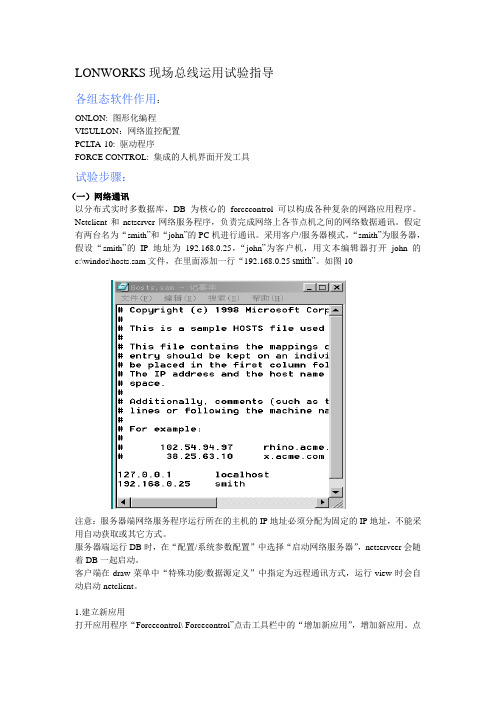
采用客户/服务器模式,“smith”为服务器,假设“smith”的IP地址为192.168.0.25,“john”为客户机,用文本编辑器打开john的c:\windos\hosts.sam文件,在里面添加一行“192.168.0.25 smith”。
如图10图10注意:服务器端网络服务程序运行所在的主机的IP地址必须分配为固定的IP地址,不能采用自动获取或其它方式。
服务器端运行DB时,在“配置/系统参数配置”中选择“启动网络服务器”,netserveer会随着DB一起启动。
客户端在draw菜单中“特殊功能/数据源定义”中指定为远程通讯方式,运行view时会自动启动netclient。
1.建立新应用打开应用程序“Forcecontrol\ Forcecontrol”点击工具栏中的“增加新应用”,增加新应用。
点击“进入组态”,进行编辑。
2.定义数据源选择“数据源”,在客户端定义一个新数据源,各参数如下:名称:smithDB服务/主机名:smith方式:使用PC数据库,如图11图113.定义变量在draw中建立一个新变量,名为tag3.pv,指定其为DB型变量,数据源指定一栏选“smithDB”现在,客户端中的变量tag3.pv与服务数据库中的过程中tag3.pv及现场I/O之间建立了一个数据链路。
在客户端,可用变量tag3.pv完成动画连接、趋势显示、报警显示或编辑脚本程序,以反映tag3.pv这个过程I/O点的变化。
力控组态软件教程
力控组态软件教程第一节选型及安装力控通用监控组态软件的正式发行企业版分为开发版和运行版,软件是根据点数进行计价的,点数是指实际监控的外部I/O设备参数的个数,即软件内部的实时数据库DB中I/O连接项的个数,软件内部的中间变量、间接变量等不计点。
力控演示版的开发版和运行版分别有64点的限制,完全免费的不限点数的开发版可以直接咨询三维力控销售部和各地办事处,索要注册号即可以使用,力控正式发行的开发版没有点数和时间的限制,购买软件时,开发版随运行版免费赠送,运行版分为通用监控版、WWW网络版等。
1. 力控的运行版本1) 通用监控版运行在单台PC上完成监控,该版本不包括扩展组件。
2) 标准网络版由2套通用监控版软件通过以太网可以构成标准的服务器/客户端应用模式,标准服务器端只授权5客户使用,客户端在5个客户端的基础上可增加10、20、50、无限客户端。
3) WWW网络版用标准的IE浏览器作为“瘦”客户端,在Internet/Intranet上来监控WWW 服务器的上的数据,瘦客户端在5个客户端的基础上可增加10、20、50、无限客户端。
2. 扩展组件包括PC控制策略程序、GPRS组件、数据库ODBC通讯组件、CommServer通讯组件、DataServer数据转发组件、远程数据库历史备份程序等组件。
3.系统要求1)硬件配置目前市面上流行的机型完全满足力控的运行要求,推荐配置如下:CPU:Pentium(R) 4 CPU 2.0GHz以上。
内存:512M以上。
显示器:VGA、SVGA以及支持桌面操作系统的图形适配器,显示256色以上。
并行口或USB口:安装产品授权的加密锁。
2)软件要求软件没有经过授权,也可以开发和运行,但有如下限制:数据库连接项支持64点,运行系统在线运行时间是1小时。
软件支持的操作系统:WINNT4.0(补丁6)/WIN2000 /WINXP/WIN 2003。
可用于win XP、win7,win10未试过,估计可以?3)硬件加密锁软件是通过硬件加密锁进行授权,软件经过授权后可以长时间运行,产品提供的加密锁包括:并口硬件加密锁和USB口硬件加密锁,硬件加密锁使用前必须安装驱动程序。
力控lonworks驱动开关量补充说明(新驱动)

处理“100. 0/100. 1 ”这种类型的数据类型,如果要读或者写最后一位开关量,组点可以参考上图的配置。
组成pv点。
数据地址:1,数据类型byte.如果要取此开关量的“100. 0”中的100,组成pv点。
数据地址:0,数据类型byte.这个时候的实际显示值并不一定是100,但是一个对应关系,需要用户自己参考说明书来了解。
用户可以反向推断如果100对应200,0对应0,那么可以下置200来将该值改成100。
处理“ST_ON/ST_OFF”这种开关量,组成pv点。
数据地址:0,数据类型byte.。
一般写4对应ST_ON,写0表示ST_OFF,这是一般情况,很多情况,需要用户自己参考说明书。
以下是我参考过的说明“100. 0/100. 1 ”这种数据类型的一种说明Version 12June 2003SNVT Master ListLO N MARK ®SNVT Master ListSNVT_switch (95)SwitchA structure reporting a percentage level or load value and a discrete on/off state. Separate fields report the percentage value and state. This type should be used for both discrete (on/off) and analog control.The value field is used to control the load's value, i.e. position, speed, or intensity, the state field being used to control whether the load is on or off (enabled or disabled).When used as the output of a discrete sensor device, the OFF state is represented by a SNVT_switch network variable with state = FALSE and value = 0. The other discrete states are represented by state = TRUE and value > 0. When used as the output of a two-state sensor device, the ON state is represented by state = TRUE and value = 200 (meaning 100%).When used as the input of a two-state discrete actuator, a SNVT_switch network variable with state = TRUE will be interpreted as the ON state if value > 0, and as the OFF state if value = 0. Additionally, a SNVT_switch input network variable with state = FALSE should be interpreted as the OFF state, whether or not value = 0. A state value of 0xFF indicates the switch value is undefined. Input Network Variablevalue (raw) state 2-state interpretationany 0 off (0; 0)0 1 off (0; 1)>0 1 on (200; 1)any -1 (0xFF) invalid (no action)Output Network Variablevalue (raw) state 2-state interpretation0 0 off200 (0xC8) 1 on0 .. 200 (0 .. 0xC8)(any valid value)-1 (0xFF) invalid (NULL)。
AELTA LonWorks (CME-LW01) 说明书

status)与令其 Neuron chip 传送本身的 Neuron ID 至 Lon Works 网络。 当 CME-LW01 藉由网络整合工具连上 LonWorks 网络前,使用者需按压 Service Pin
第一章 概述
1.1 nTalk 通讯的转换界面,透过 LonWorks 网络整合工具对 CME-LW01 组态(Configure)完成后,CME-LW01 即可运行于 LonWorks 网络。
本手册提供 CME-LW01 的安装与设定,以使台达变频器可藉由 CME-LW01 而连接至 LonWorks 网络。(CME-LW01 所支持变频器的版本如下表 1-1 所示。)
4.2 功能简表(Functional Profile) ........................................................... 12 4.3 使用 CME-LW01 与变频器通讯............................................................ 12 4.4 读/写变频器参数 .................................................................................. 13 4.5 运转/停止命令 ...................................................................................... 15 4.6 送频率命令给变频器 ............................................................................ 15 第五章 错误讯息指示与故障排除 .................................................................... 17 5.1 Power LED .......................................................................................... 17 5.2 SP LED................................................................................................ 17 5.3 Service LED ........................................................................................ 18
LonWorks系统集成说明

概述1安装Intouch。
如果您使用的是Intouch7.0,请在安装完Intouch7.0后安装其补丁包Intouch7.0SP2Patch04(English).exe。
2安装PCNSI卡。
3如果您使用Windows环境组态,请安装LonTek组态软件及LNS DDE Server软件;如果您使用Dos环境组态,请安装以下软件:LonProfiler、LonMake for Dos和LonManger DDE Server。
安装IntouchIntouch是WonderWare公司FactorySuite软件包的一个组件,它提供了一个高度集成的,基于对象的可视化编程环境,适用于开发大型人机界面软件(HMI)。
安装Intouch的系统要求:安装Intouch在安装过程中,您可以选择安装下列产品:1.Intouch开发系统,包括所有建造和运行HMI应用程序的工具(此系统包含运行系统)。
2.Intouch运行系统,此系统用于工厂现场操作员与人机界面(HMI)的实时互动。
3.FactoryFocus,只用于现场监视,无操作性。
安装过程:1.将FactorySuite2000光盘放入光驱,光盘自动运行。
出现左面的画面。
2.点击InTouch3.出现System Files安装界面,将安装FactorySuite2000软件包的一批通用组件(FactorySuite2000 Common Components)。
4.文件被复制到硬盘上,同时配置计算机系统。
5.如果以前没有安装过Adobe Acrobat,将提示您安装。
6.出现安装Intouch的路径对话框。
7.出现选择组件的对话框,如上左。
建议全部选取。
8.出现配置选项的对话框,如上右。
建议选择完全开发系统。
9.选择需要的选项。
点击Next。
10.出现开始拷贝文件的对话框。
11.结束安装。
对话框提示您重起系统。
注意:如果您使用的是Intouch7.0版,请在安装完Intouch7.0后安装其补丁包Intouch7.0SP2Patch04(English).exe。
日立空调机组GW协议转换器使用说明书
——目录——1.LONWORKS技术概况2.G/W协议转换器3.机组测的设定和接线4.试运行5.LONWORKS变量SNVT定义6.报警代码转换表1.LONWORKS技术概况美国Echelon公司1991年推出的LON技术,又称LONWORKS技术是计算机控制技术第三代的现场总线技术。
LONWORKS技术是一个实现控制网络系统的完整平台。
这些网络包括智能设备或节点。
括智能设备或节点与它们所处的环境进行交互作用,以及通过不同的通信介质与其它节点进行通信。
这种通信采用一种通用的、基于消息的控制协议-LONTALK协议。
由于LONTALK协议已固化在神经元芯片(微处理器)内,节点通过网络变量的形式交换信息,又有现成的网络管理工具进行网络管理。
所以建立一个LONWORKS控制网络在网络通讯上几乎不需要任何调试工作量。
LONWORKS技术的网络通信对用户是透明的,神经元芯片自动完成LONWORK S的所有七层的网络协议,用户所要作的只有两件事:第一件事是指定哪些信息是通过网络变量传递的,也就是定议网络变量;第二件事是指定信息传递传递的发起者和接收者,也就是做Binding(网络变量的捆绑)。
2.G/W协议转换器(其型号为HARC70-C)G/W协议转换器是日立公司提供的通信用网关设备(可简称G/W)。
是把广州日立冷机有限公司内部用的H-link通信协议转换成公开的LONTALK协议的设备。
是便于用户通过通信网络监控日立的冷水机组为目的开发的一种通信协议转换器。
1)系统构成方式以下是用G/W协议转换器联接到BMS(楼宇控制系统)系统时的系统构成简图。
对于构成系统的其它部品请参阅相应的使用说明书。
注意事项:1)冷水机组测的通信线上一定要加上附带的线圈和电容。
2)屏蔽线要采用D类接地标准备注:上位装置可使用LONWORKS /RS232C型的G/W(ECHELON制SLTA-10 通用的LONTALK 收发器等)及相应的软件。
- 1、下载文档前请自行甄别文档内容的完整性,平台不提供额外的编辑、内容补充、找答案等附加服务。
- 2、"仅部分预览"的文档,不可在线预览部分如存在完整性等问题,可反馈申请退款(可完整预览的文档不适用该条件!)。
- 3、如文档侵犯您的权益,请联系客服反馈,我们会尽快为您处理(人工客服工作时间:9:00-18:30)。
LonWorks配置文档(2008.06初版)一、 LonWorks概述LonWorks是美国Echelon公司1992年推出的局部操作网络(Local Operating Network),最初主要用于楼宇自动化,但很快发展到工业现场网。
LonWorks技术为设计和实现可互操作的控制网络提供了一套完整、开放、成品化的解决途径。
LonWorks技术的核心是神经元芯片(Neuron Chip)。
该芯片内部装有3个微处理器:MAC处理器完成介质访问控制;网络处理器完成OSI的3~6层网络协议;应用处理器完成用户现场控制应用。
它们之间通过公用存储器传递数据。
LonTalk是LonWorks的通信协议,固化在神经元芯片内。
LonTalk局部操作网络协议是为LonWorks 中通信所设的框架,支持ISO组织制定的OSI参考模型的7层协议,并可使简短的控制信息在各种介质中非常可靠地传输。
LonTalk协议是直接面向对象的网络协议,具体实现即采用网络变量的形式。
又由于硬件芯片的支持,使它实现了实时性和接口的直观、简洁等现场总线的应用要求。
二、 常用软硬件工具1.Windows2000或Windows XP操作系统。
Windows2000为sp4及以上,Windows XP为sp1及以上。
推荐使用windows2000操作系统。
2.网卡及网卡驱动程序:PCLTA-20。
3.Office2000 Visio软件。
4.LonMaker网络管理软件。
5.常用工具:普通数字万用表、小“一”字螺丝刀、偏口钳或其他可替代工具。
三、 软硬件安装1.安装Lon网卡,并使之与Lon控制设备组成网络;安装Lon网卡驱动程序。
LON网卡与普通网卡外形相似,也需要安插到主板上的PCI插槽中使用,LON网卡的接口为两针端子,无极性;它既不同于普通网卡的RJ45水晶头形式,也不同于有A+、B-极性的485网络,因此LON 网络的通讯线采用五类双绞线,即常用的普通网线(UTP-5)即可。
关机掉电,将LON网卡安装在主板上,重新上电开机,操作系统应该检测到新的硬件。
安装LON 网卡厂家提供的驱动程序。
2.安装Windows Visio20003.安装LonMaker。
安装完后,将Lon设备厂家提供的模块资源文件拷贝到LonMaker安装目录下的Import文件夹。
四、 配置过程1.Lon网卡的属性配置、通讯测试在用LonMaker组网前,需要对网卡进行设置、测试,然后才能接入外部的Lon网络设备。
先看看在控制面板中新增的一些图标:如图所示,图标1和图标3是在安装完LonMaker 后生成的,图标2是在安装了网卡驱动程序之后生成的。
通过运行图标2引导的程序对网卡进行设置、诊断。
图标1和3主要用于远程网络接口及以服务器方式访问的IP地址、端口设置等。
双击“LonWorks?plug‘n Play”进入LonWorks的设置及测试界面,如下图:正确选择Device和NI Application,点击“Diagnostics”进入通讯诊断程序界面,如下图:出现下面的对话框(一些数值可能会不同):点击图中的“Test”按钮,网卡正常通讯的话会上传测试数据(一些数值可能会不同)如下图:如上图,显示没有任何错误和超时表明网络正常。
如果网卡通过测试,我们知道计算机已经可以跟Lon网络接口进行通讯了。
下一步就要确认一下网卡是否也能跟设备(模块)进行正确的通讯。
选一模块上电并将其正确连接到Lon总线上,点击“Comm”按钮:系统将弹出下面的对话框,点击“是(Y)”按钮系统显示等待pin按键消息,如下图:这时用小“一”字螺丝刀按一下模块左上方的“维护”按键,则出现Neuron ID号,如下图:如果系统收不到pin按键信息,检查网卡接线端子、模块接线端子是否虚接;网线是否短路或断路;模块网络接口是否损坏或者尝试通讯其他模块。
Neuron ID号是12位十六进制数字,类似于烟感、温感探头的一次码,对于每个DDC模块而言该号码唯一,对总线上的所有设备完成通讯测试,记录ID号并对进行设备描述,以便在使用LonMaker配置设备功能模块属性时对设备进行有效区分。
完成对Lon总线所有设备的通讯测试后,点击“OK”键退出“诊断测试”框.。
再次点击“OK”键退出“LON WORKS Plug N’ Play application”。
2.新建Lon网络工程启动LonMaker for Windows点击“New Network”建立一个新的网络工程或点击“Open Network”打开已有的工程,如下图:输入网络工程名称,如下图:选择连接的网络接口,如下图:上图中,如果“Network Interface Name”为空,参考前述步骤中有关网卡安装说明查看网卡是否为当前系统所识别,是否“Apply”应用了网卡的属性配置。
选择网络设备“DDC”的管理模式:在线或不在线。
如下图:选择需要注册到Lon网络文件中功能插件。
依据网络上设备类型选择需要注册到Lon文件中的插件程序,因此在之前的拷贝模块资源文件时要先了解网络中所挂接的设备类型,再拷贝到Import目录下。
进入Lon网络编辑界面“Windows Visio”中,如下图:如下图:拖放后出现如下对话框,输入设备名称,用于描述网络设备。
勾选“Commission Device”以使设备在线。
点击下一步,选择要下载的模块资源文件选择要下载的模块资源文件此例中可以看出模块资源文件预览指向的地址为LonWorks下的Import目录,这就是为什么我们要将所需的模块资源文件拷贝的此目录下。
当然我们也可以不将模块资源文件复制在此,而通过重新指定查找范围将默认地址变更为模块资源文件原文件所在目录。
缺点:可能变更Visio绘图软件中图形模版的默认地址,使得当拖入图形时产生程序指向错误而需要重新指定地址。
点击下一步,选择信道类型,设备所在的通道,如下图:点击下一步,如图显示设备描述及检测间隔点击下一步,设置设备识别方式,我们选择“Neuron ID”方式,输入在进行Lon卡通讯时,所获得的设备“Neuron ID”。
如下图:下载模块资源文件,如下图:确认设备初始状态和配置属性资源添加设备完毕,通讯正常时设备图形为绿色右键单击“Device 1”,如下图:选择“Browse”,弹出“LonMaker Browser”,如下图:图中,蓝色为模块中实际点,也就是我们要应用的点;灰色为虚点。
对蓝色点,我们可以强制下载。
五、 力控组态1.IO组态如图所示,新建IO设备通信方式选择“同步”,如下图:点击下一步,对LNS设备进行定义,选择配置好的接口和已经创建的网络工程。
创建监控点集,如下图:通常第一次工程组态时要勾选“启动时重建LNS监控点集”。
详述见下面数据库组态部分。
单击确认,完成IO设备组态,如下图:创建模拟I/O点,如下图:点击“数据连接”页签,进入数据连接对话框,如下图:有两种数据连接方式:(1) 连接数据点的“DESC”参数:点击“增加”,如下图:上图中,监控数据方式选择“监控集”方式,选择已经建立的监控集,传送格式选择“格式化字符串”。
然后点击“添加到监控集”把刚才连接的点添加到上述的监控集中。
注意:前述IO设备组态时的“启动时重建LNS监控点集”,通常在工程第一次组态时应用。
这样工程运行后把所有连接的点建立监控集(如果点数多会花费很长时间)。
而在修改组态时可以应用这里的“添加到监控集”和“从监控集中删除”,这样工程重启动时就不必把所有的点重新再建监控集,而只是把修改的点添入监控集或从监控集中删除,可以节省很多时间。
(2) 连接数据点的“PV”参数,选中“PV”项:点击“增加”。
见下图,传送格式选择“原始字节数据”:数据地址选择“0”,,数据类型选择“BYTE(8位无符号)”,如下图:关于“数据地址”和“数据类型”的详细介绍见附件。
力控组态完毕。
3.运行力控,进入实时数据库系统,见下图:在本例中,tag1以“DESC”参数、tag2以“PV”参数分别连接到“Device1”的“Nvi_DO0”。
我们可以分别通过设置tag1.DESC的ON/OFF状态和tag2.PV的值(0和4)来强制“Nvi_DO0”的开/关。
如以下几幅图:4.注意事项Lon通讯(上位机和Lon设备)传输的是字符串,Lon设备的网络变量的设备数据类型和上位机的数据类型基本都可以采集字符串的通讯方式数据类型的不匹配导致通讯出现故障等问题,数据下置的内容不对,比如开为1也可能为ST_ON也可能为ST_LOW,关为0也可能为ST_OFF,也可能为ST_HIGH附件处理“100. 0/100. 1 ”这种类型的数据类型,如果要读或者写最后一位开关量,组点可以参考上图的配置。
组成pv点。
数据地址:1,数据类型 byte.如果要取此开关量的“100. 0”中的100,组成pv点。
数据地址:0,数据类型 byte.这个时候的实际显示值并不一定是100,但是一个对应关系,需要用户自己参考说明书来了解。
用户可以反向推断如果100对应200,0对应0,那么可以下置200来将该值改成100。
处理“ST_ON/ST_OFF”这种开关量,组成pv点。
数据地址:0,数据类型 byte.。
一般写4对应ST_ON,写0表示ST_OFF,这是一般情况,很多情况,需要用户自己参考说明书。
以下是我参考过的说明“100. 0/100. 1 ”这种数据类型的一种说明Version 12June 2003SNVT Master ListLO N MARK ®SNVT Master ListSNVT_switch (95)SwitchA structure reporting a percentage level or load value and a discrete on/off state. Separate fields report the percentage value and state. This type should be used for both discrete (on/off) and analog control.The value field is used to control the load's value, i.e. position, speed, or intensity, the state field being used to control whether the load is on or off (enabled or disabled).When used as the output of a discrete sensor device, the OFF state is represented by a SNVT_switch network variable with state = FALSE and value = 0. The other discrete states are represented by state = TRUE and value > 0. When used as the output of a two-state sensor device, the ON state is represented by state = TRUE and value = 200 (meaning 100%).When used as the input of a two-state discrete actuator, a SNVT_switch network variable with state = TRUE will be interpreted as the ON state if value > 0, and as the OFF state if value = 0. Additionally, a SNVT_switch input network variable with state = FALSE should be interpreted as the OFF state, whether or not value = 0. A state value of 0xFF indicates the switch value is undefined. Input Network Variablevalue (raw) state 2-state interpretationany 0 off (0; 0)0 1 off (0; 1)>0 1 on (200; 1)any -1 (0xFF) invalid (no action)Output Network Variablevalue (raw) state 2-state interpretation0 0 off200 (0xC8) 1 on0 .. 200 (0 .. 0xC8)(any valid value)-1 (0xFF) invalid (NULL)。
