交换机VRRP配置
华为QUIDWAY3900 系列华为交换机操作手册---21-VRRP操作

VRRP 将局域网的一组交换机(包括一个 Master 即主交换机和若干个 Backup 即备 份交换机)组织成一个虚拟路由器,这组交换机被称为一个备份组。
Network
Actual IP address10.100.10.2 Master
Virtual IP address10.100.dway S3900 系列以太网交换机 操作手册-Release 1510 VRRP
1.1.1 虚拟路由器简介
第 1 章 VRRP 配置
备份组内的交换机在使能 VRRP 协议后,会虚拟出一个虚拟路由器。用户可以在虚 拟路由器上进行相关的配置。
1. 配置虚拟路由器的 IP 地址
虚拟路由器的 IP 地址可以是备份组所在网段中未被分配的 IP 地址,也可以是备份 组中成员交换机的接口 IP 地址。虚拟路由器的 IP 地址具有以下的特性:
z 备份组内的交换机也有自己的 IP 地址(如 Master 的 IP 地址为 10.100.10.2, Backup 的 IP 地址为 10.100.10.3)。
z 局域网内的主机仅仅知道这个虚拟路由器的 IP 地址 10.100.10.1(通常被称为 备份组的虚拟路由器的 IP 地址),而不知道具体的 Master 交换机的 IP 地址 10.100.10.2 以及 Backup 交换机的 IP 地址 10.100.10.3。
用户可以在使能 S3900 交换机的 VRRP 特性之前,设定备份组内的交换机是否能够 使用 ping 命令来 ping 通备份组的虚拟路由器的 IP 地址,从而避免以上情况的发生。 但如用户已使能了 VRRP 特性,则系统不允许用户再设定虚拟路由器的 IP 地址是否 可 ping 通。
2. 配置虚拟路由器的 IP 和 MAC 地址之间的关系 S3900 交换机在保证子网数据正确转发的基础上,还提供如下功能:
交换机VRRP配置

VRRP原理虚拟路由器冗余协议(VRRP)是一种标准化协议,主要用于非cisco设备厂商。
它可以把一个虚拟路由器的责任动态分配到局域网上的VRRP 路由器中的一台。
控制虚拟路由器IP 地址的VRRP 路由器称为主路由器,它负责转发数据包到这些虚拟IP 地址。
一旦主路由器不可用,这种选择过程就提供了动态的故障转移机制,这就允许虚拟路由器的IP地址可以作为终端主机的默认第一跳路由器。
使用VRRP 的好处是有更高的默认路径的可用性而无需在每个终端主机上配置动态路由或路由发现协议。
VRRP 包封装在IP包中发送。
在一个VRRP组内的多个路由器共用一个虚拟的物理地址和I P地址,该地址被作为局域网内所有主机的缺省网关地址。
VRRP协议决定哪个路由器被激活,该被激活的路由器接收发过来的数据包并进行路由。
组内的各路由器之间交换呼叫信号,如果当前路由器变得无法使用,备用路由器将进入激活状态,接管路由任务。
VRRP配置命令:1) 华为系列交换机配置:vrrp ping-enable:根据VRRP的标准协议,备份组的虚拟IP地址是无法使用ping命令来ping通的。
此命令可以使用户能够使用ping命令来ping通备份组的虚拟IP地址。
如果需要主机可以ping通网关,则此命令必须在配置vrrp之前使能。
vrrp vrid virtual-router-ID virtual-ip virtual-address:将一个本网段的IP地址指定到一个虚拟路由器vrrp vrid virtual-router-ID priority priority-value:设置路由器在备份组中的优先级,优先级越大,越有机会成为备份组中的主设备。
vrrp vrid virtual-router-ID preempt-mode [ timer delay delay-value ]:设置路由器抢占模式。
在非抢占方式下,一旦备份组中的某台路由器成为Master,只要它没有出现故障,其它路由器即使随后被配置更高的优先级,也不会成为Master。
H3C交换机设置VRRP

H3C机设置VRRP在支持标准VRRP模式的H3C机设置VRRP 功能,主要包括创建备份组、添加虚拟器IP 地址、启用虚拟路由器IP 地址、配置备份组优先级等基本功能,以及包括配置备份组成员交换机的抢占方式、VRRP 认证方式、VRRP 定时器和VRRP 监视功能等高级配置。
在支持负载均衡VRRP 模式的H3C 交换机中,首先还要对交换机设置VRRP 的工作模式。
下面分别予以介绍。
VRRP 工作模式配置本节仅适用于同时支持标准VRRP 模式和负载均衡VRRP 模式的H3C 交换机,如58 系列和S9500E 系列交换机。
配置VRRP 的工作模式后,路由器上所有的VRRP 备份组都工作在该模式。
VRRP 工作模式的配置步骤如表4-2所示。
表4-2 VRRP 工作模式的配置步骤【注意】通过本命令配置VRRP 的工作模式后,基于IPv4 和IPv6 的备份组均工作在指定的模式。
VRRP 工作在负载均衡模式时,要求备份组虚拟IP 地址和VRRP 备份组中交换机物理端口的IP 地址不能相同,且虚拟IP 地址需要与虚拟MAC 地址对应,也不能采用VRRP 备份组中交换机物理端口上的实际MAC 地址。
否则,VRRP 负载均衡功能将无法正常工作。
创建VRRP 备份组后,仍然可以修改VRRP 的工作模式。
修改VRRP 的工作模式后,路由器上所有的备份组都工作在该模式。
以下示例是配置VRRP 工作在负载均衡模式。
<Sysname>systemview ?[Sysname]?vrrp?mode?loadbalance?H3C交换机设置VRRP 基本功能在标准模式下配置H3C 交换机的VRRP 基本功能,涉及到一个重要的知识点,那就是VRRP 备份控制VLAN。
也就是VRRP 报文终结的VLAN。
VLAN 终结是指某个端口在接收到VLAN 报文后去掉报文中的VLAN 标记,再进行三层转发或其他处理。
VLAN 终结分为:明确终结:终结特定的VLAN。
H3C交换机设置简单主备备份模式的VRRP应用示例

H3C交换机设置简单主备备份模式的VRRP应用示例H3C交换机设置简单主备备份模式的VRRP应用示例VRRP 的最简单应用就是主备备份模式,就是创建一个VRRP 备份组,然后在这个备份组中指定或选举一个Master 交换机,备份组中的其他交换机均为Backup 交换机。
平时只有Master 交换机担当数据转发任务,只有在Master 交换机失效,或者重新选择新的Master 交换机时,Backup 交换机中的一台才可能接替原来Master 交换机的工作。
但任一时刻实际上都只有Master 一台交换机担当数据转发任务,备份组中的其他交换机只是起到一个备份的作用。
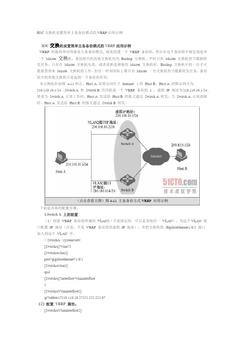
本示例拓扑如图4-11所示。
Host A 需要访问位于Internet 上的Host B,Host A 的默认网关为210.110.10.1/24 。
Switch A 和Switch B 共同组成一个VRRP 备份组1 ,虚拟IP 地址为210.110.10.1/24。
要求当Switch A 正常工作时,Host A 发送给Host B 的报文通过Switch A 转发;当Switch A 出现故障时,Host A 发送给Host B 的报文通过Switch B 转发。
下面是具体的配置步骤。
1.Switch A 上的配置(1)创建VRRP 备份组所属的VLAN2(不是固定的,可以是其他任一VLAN),为这个VLAN 接口配置IP 地址(注意,不是VRRP 备份组的虚拟IP 地址),并把交换机的Gigabitethernet1/0/5 接口加入到这个VLAN 中。
< SwitchA >systemview[SwitchA]?vlan?2[SwitchAvlan2]port?gigabitethernet?1/0/5[SwitchAvlan2]quit[SwitchA]?interface?vlaninterface2[SwitchAVlaninterface2]ip?address?210.110.10.2?255.255.255.0?(2)配置VRRP 属性。
vrrp基本命令

vrrp基本命令
VRRP(Virtual Router Redundancy Protocol,虚拟路由器冗余协议)的基本命令可以概括为以下几个步骤:
1.配置VRRP备份组:在接口视图下,使用命令“vrrp vrid virtual-router-id virtual-ip virtual-address”来创建VRRP备份组并给备份组配置虚拟IP地址。
2.配置VRRP备份组的优先级:使用命令“vrrp vrid virtual-router-id priority priority-value”来配置交换机在备份组中的优先级。
缺省情况下,优先级的取值是100。
数值越大,优先级越高,越可能成为Master设备。
3.配置VRRP备份组的虚拟IP地址:使用命令“vrrp vrid virtual-router-id virtual-ip virtual-address”来配置VRRP备份组的虚拟IP地址。
4.查看VRRP备份组的状态:使用命令“show vrrp brief”来查看VRRP备份组的状态,包括接口状态、虚拟IP地址、优先级等信息。
以上是VRRP的基本命令,具体实现还需要根据不同厂商的设备进行具体配置。
VRRP配置实验报告

课程名称网络设计与系统集成实验名称VRRP配置7.1实验目的1.掌握三层交换机的VRRP功能。
2.掌握三层交换机的VRRP配置。
7.2实验设备三层交换机3台,二层交换机1台,PC机3台,网线若干。
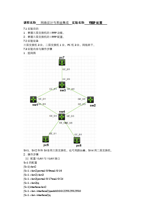
7.3实验内容与操作步骤1.组网图SW1、SW2和和SW3用三层交换机,也可用路由器,SW4用二层交换机。
2.操作步骤(1)配置VLAN与VLAN接口Sw1的配置[Sw1]vlan2[Sw1-vlan2]porte1/0/9toe1/0/16[Sw1-vlan2]vlan3[Sw1-vlan3]porte1/0/17toe1/0/24[Sw1-vlan3]q[Sw1]interfacevlan2[Sw1-vlan-interface2]ipadd10.0.0.2255.255.255.0[Sw1-vlan-interface2]q[Sw1]interfacevlan3[Sw1-vlan-interface3]ipadd20.0.0.1255.255.255.0 Sw2的配置[Sw2]vlan2[Sw2-vlan2]porte1/0/9toe1/0/16[Sw2-vlan2]vlan3[Sw2-vlan3]porte1/0/17toe1/0/24[Sw2-vlan3]q[Sw2]interfacevlan2[Sw2-vlan-interface2]ipadd10.0.0.3255.255.255.0 [Sw2-vlan-interface2]q[Sw2]interfacevlan3[Sw2-vlan-interface3]ipadd30.0.0.1255.255.255.0 Sw3的配置[Sw3]vlan2[Sw3-vlan2]porte1/0/1toe1/0/8[Sw3-vlan2]vlan3[Sw3-vlan3]porte1/0/9toe1/0/16[Sw3-vlan3]vlan416[Sw3-vlan4]porte1/0/17toe1/0/24[Sw3-vlan4]q[Sw3]interfacevlan2[Sw3-vlan-interface2]ipadd20.0.0.2255.255.255.0 [Sw3-vlan-interface2]q[Sw3]interfacevlan3[Sw3-vlan-interface3]ipadd30.0.0.2255.255.255.0 [Sw3-vlan-interface3]q[Sw3]interfacevlan4[Sw3-vlan-interface3]ipadd40.0.0.1255.255.255.0 (2)配置交换机之间的路由Sw1的配置[Sw1]rip[Sw1-rip-1]network10.0.0.0[Sw1-rip-1]network20.0.0.0Sw2的配置[Sw2]rip[Sw2-rip-1]network10.0.0.0[Sw2-rip-1]network30.0.0.0Sw3的配置[Sw3]rip[Sw3-rip-1]network30.0.0.0[Sw3-rip-1]network30.0.0.0[Sw3-rip-1]network40.0.0.0配置完成后,验证个交换机之间路由的是否正常。
交换机VRRP配置

交换机VRRP配置I PPC1SwitchB通过E0/24与SwitchC相连,通过E0/23上行交换机SwitchA通过ethernet 0/24与SwitchB的ethernet 0/24连接到SwitchCSwitchA和SwitchB上分别创建两个虚接口,interface vlan 10和interface 20做为三层接口,其中interface vlan 10分别包含ethernet0/24端口,interface 20包含ethernet 0/23端口,做为出口。
『组网需求』SwitchA和 SwitchB之间做VRRP,interface vlan 10做为虚拟网关接口,Switch A为主设备,允许抢占,SwitchB为从设备,PC1主机的网关设置为VRRP虚拟网关地址192.168.100.1,进行冗余备份。
访问远端主机PC210.1.1.1/242 数据配置步骤『两台交换机主备的配置流程』通常一个网络内的所有主机都设置一条缺省路由,主机发往外部网络的报文将通过缺省路由发往该网关设备,从而实现了主机与外部网络的通信。
当该设备发生故障时,本网段内所有以此设备为缺省路由下一跳的主机将断掉与外部的通信。
VRRP就是为解决上述问题而提出的,它为具有多播或广播能力的局域网(如以太网)设计。
VRRP可以将局域网的一组交换机(包括一个Master即活动交换机和若干个Backup即备份交换机)组织成一个虚拟路由器,这组交换机被称为一个备份组。
虚拟的交换机拥有自己的真实IP地址(这个IP地址可以和备份组内的某个交换机的接口地址相同),备份组内的交换机也有自己的IP地址。
局域网内的主机仅仅知道这个虚拟路由器的IP地址(通常被称为备份组的虚拟IP地址),而不知道具体的Master交换机的IP地址以及Backup交换机的IP地址。
局域网内的主机将自己的缺省路由下一跳设置为该虚拟路由器的IP地址。
于是,网络内的主机就通过这个虚拟的交换机与其它网络进行通信。
思科交换机+vrrp+mstp配置实例

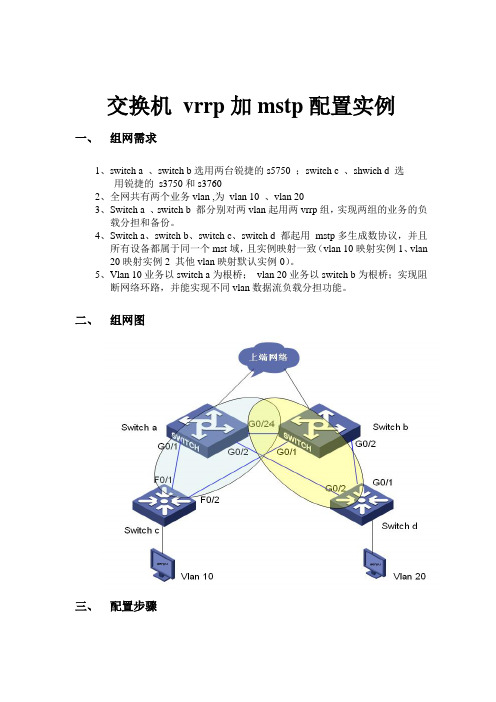
交换机vrrp加mstp配置实例一、组网需求1、switch a 、switch b选用两台锐捷的s5750 ;switch c 、shwich d 选用锐捷的s3750和s37602、全网共有两个业务vlan ,为vlan 10 、vlan 203、Switch a 、switch b 都分别对两vlan起用两vrrp组,实现两组的业务的负载分担和备份。
4、Switch a、switch b、switch c、switch d 都起用mstp多生成数协议,并且所有设备都属于同一个mst域,且实例映射一致(vlan 10映射实例1、vlan 20映射实例2 其他vlan映射默认实例0)。
5、Vlan 10业务以switch a为根桥;vlan 20业务以switch b为根桥;实现阻断网络环路,并能实现不同vlan数据流负载分担功能。
二、组网图三、配置步骤Switch a配置:s1#show runBuilding configuration...Current configuration : 1651 bytes!version RGNOS 10.2.00(2), Release(29287)(Tue Dec 25 20:39:14 CST 2007 -ngcf49) hostname s1co-operate enable!!!vlan 1!vlan 10!vlan 20!!no service password-encryption!spanning-tree 开启生成树(默认为mstp)spanning-tree mst configuration 进入mst配置模式revision 1 指定MST revision number 为1name region1 指定mst配置名称instance 0 vlan 1-9, 11-19, 21-4094 缺省情况下vlan都属于实例0instance 1 vlan 10 手工指定vlan10属于实例1instance 2 vlan 20 手工指定vlan20属于实例2spanning-tree mst 1 priority 0 指定实例1的优先级为0(为根桥)spanning-tree mst 2 priority 4096 指定实例2的优先级为4096interface GigabitEthernet 0/1switchport access vlan 10 配置g0/1属于vlan10!interface GigabitEthernet 0/2switchport access vlan 20 配置g0/2属于vlan 20!interface GigabitEthernet 0/3!..interface GigabitEthernet 0/24 设置g0/24为trunk接口且允许vlan10/20通过switchport mode trunk!interface VLAN 10 创建vlan 10 svi接口ip address 192.168.10.1 255.255.255.0 配置ip地址vrrp 1 priority 120 配置vrrp组1 优先级为120vrrp 1 ip 192.168.10.254 配置vrrp组1虚拟ip地址为192.168.10.254!interface VLAN 20 创建vlan 20 svi接口ip address 192.168.20.1 255.255.255.0 配置ip地址vrrp 2 ip 192.168.20.254 配置vrrp组2虚拟ip地址为192.168.20.254默认vrrp组的优先级为100默认不显示!line con 0line vty 0 4logins1#show vlanVLAN Name Status Ports---- -------------------------------- --------- ----------------------------------1 VLAN0001 STATIC Gi0/3, Gi0/4, Gi0/5, Gi0/6Gi0/7, Gi0/8, Gi0/9, Gi0/10Gi0/11, Gi0/12, Gi0/13, Gi0/14Gi0/15, Gi0/16, Gi0/17, Gi0/18Gi0/19, Gi0/20, Gi0/21, Gi0/22Gi0/23, Gi0/2410 VLAN0010 STATIC Gi0/1, Gi0/2420 VLAN0020 STATIC Gi0/2, Gi0/24Switch b配置:s2#show runBuilding configuration...Current configuration : 1607 bytes!version RGNOS 10.2.00(2), Release(27932)(Thu Dec 13 10:32:09 CST 2007 -ngcf31) hostname s2!!!vlan 1!vlan 10!vlan 20!!no service password-encryption!spanning-treespanning-tree mst configurationrevision 1name region1instance 0 vlan 1-9, 11-19, 21-4094instance 1 vlan 10instance 2 vlan 20spanning-tree mst 1 priority 4096spanning-tree mst 2 priority 0interface GigabitEthernet 0/1switchport access vlan 10!interface GigabitEthernet 0/2switchport access vlan 20!..interface GigabitEthernet 0/24switchport mode trunk!interface VLAN 10ip address 192.168.10.2 255.255.255.0vrrp 1 ip 192.168.10.254!interface VLAN 20ip address 192.168.20.2 255.255.255.0vrrp 2 priority 120vrrp 2 ip 192.168.20.254!line con 0line vty 0 4login!!ends2#show vlanVLAN Name Status Ports---- -------------------------------- --------- -----------------------------------1 VLAN0001 STATIC Gi0/3, Gi0/4, Gi0/5, Gi0/6Gi0/7, Gi0/8, Gi0/9, Gi0/10Gi0/11, Gi0/12, Gi0/13, Gi0/14Gi0/15, Gi0/16, Gi0/17, Gi0/18Gi0/19, Gi0/20, Gi0/21, Gi0/22Gi0/23, Gi0/2410 VLAN0010 STATIC Gi0/1, Gi0/2420 VLAN0020 STATIC Gi0/2, Gi0/24Switch c配置:s3#show runBuilding configuration...Current configuration : 1540 bytes!version RGNOS 10.2.00(2), Release(28794)(Fri Dec 21 09:27:15 CST 2007 -ngcf32) hostname s3!vlan 1!vlan 10!!service password-encryption!spanning-treespanning-tree mst configurationrevision 1name region1instance 0 vlan 1-9, 11-19, 21-4094instance 1 vlan 10instance 2 vlan 20spanning-tree mst 1 priority 0spanning-tree mst 2 priority 4096interface FastEthernet 0/1switchport access vlan 10!interface FastEthernet 0/2switchport access vlan 10!..interface GigabitEthernet 0/25!interface GigabitEthernet 0/26!interface GigabitEthernet 0/27!interface GigabitEthernet 0/28!interface VLAN 10ip address 192.168.10.3 255.255.255.0!ip route 0.0.0.0 0.0.0.0 192.168.10.254!!line con 0line vty 0 4loginSwitch d配置:s4#show runBuilding configuration...Current configuration : 1066 bytes!version RGNOS 10.2.00(2), Release(27932)(Thu Dec 13 10:31:41 CST 2007 -ngcf32) hostname s4!vlan 1!vlan 20!!no service password-encryption!spanning-treespanning-tree mst configurationrevision 1name region1instance 0 vlan 1-9, 11-19, 21-4094instance 1 vlan 10instance 2 vlan 20spanning-tree mst 1 priority 4096spanning-tree mst 2 priority 0interface GigabitEthernet 0/1switchport access vlan 20!interface GigabitEthernet 0/2switchport access vlan 20!..interface GigabitEthernet 0/12!interface VLAN 20ip address 192.168.20.3 255.255.255.0!!!!ip route 0.0.0.0 0.0.0.0 192.168.20.254!!line con 0line vty 0 4login!四、查看vrrp、mstp信息Switch a 信息:s1#show vrrp 查看vrrp 信息VLAN 10 - Group 1State is MasterVirtual IP address is 192.168.10.254 configuredVirtual MAC address is 0000.5e00.0101Advertisement interval is 1 secPreemption is enabledmin delay is 0 secPriority is 120Master Router is 192.168.10.1 (local), priority is 120Master Advertisement interval is 1 secMaster Down interval is 3 secVLAN 20 - Group 2State is BackupVirtual IP address is 192.168.20.254 configuredVirtual MAC address is 0000.5e00.0102Advertisement interval is 1 secPreemption is enabledmin delay is 0 secPriority is 100Master Router is 192.168.20.2 , priority is 120Master Advertisement interval is 1 secMaster Down interval is 3 secs1#s1#s1#s1#show spanning-tree interface gigabitEthernet 0/1 查看g0/1接口stp状态信息PortAdminPortFast : Disabled PortOperPortFast : Disabled PortAdminAutoEdge : Enabled PortOperAutoEdge : Disabled PortAdminLinkType : auto PortOperLinkType : point-to-point PortBPDUGuard : DisabledPortBPDUFilter : Disabled###### MST 0 vlans mapped :1-9, 11-19, 21-4094 PortState : forwardingPortPriority : 128PortDesignatedRoot : 8000.001a.a909.8fe0 PortDesignatedCost : 0 PortDesignatedBridge :8000.00d0.f836.ed70 PortDesignatedPort : 8001 PortForwardTransitions : 6 PortAdminPathCost : 200000 PortOperPathCost : 200000PortRole : designatedPort###### MST 1 vlans mapped :10PortState : forwardingPortPriority : 128PortDesignatedRoot : 0001.00d0.f823.ef82 PortDesignatedCost : 0 PortDesignatedBridge :0001.00d0.f823.ef82 PortDesignatedPort : 8001 PortForwardTransitions : 5 PortAdminPathCost : 200000 PortOperPathCost : 200000PortRole : rootPort###### MST 2 vlans mapped :20PortState : forwardingPortPriority : 128PortDesignatedRoot : 0002.001a.a909.8fe0 PortDesignatedCost : 0 PortDesignatedBridge :1002.00d0.f836.ed70 PortDesignatedPort : 8001 PortForwardTransitions : 4 PortAdminPathCost : 200000 PortOperPathCost : 200000PortRole : designatedPorts1#s1#s1#show spanning-tree interface gigabitEthernet 0/2 查看g0/2接口stp状态信息PortAdminPortFast : DisabledPortOperPortFast : DisabledPortAdminAutoEdge : EnabledPortOperAutoEdge : DisabledPortAdminLinkType : autoPortOperLinkType : point-to-pointPortBPDUGuard : DisabledPortBPDUFilter : Disabled###### MST 0 vlans mapped :1-9, 11-19, 21-4094PortState : forwardingPortPriority : 128PortDesignatedRoot : 8000.001a.a909.8fe0PortDesignatedCost : 0PortDesignatedBridge :8000.00d0.f836.ed70PortDesignatedPort : 8002PortForwardTransitions : 5PortAdminPathCost : 20000PortOperPathCost : 20000PortRole : designatedPort###### MST 1 vlans mapped :10PortState : forwardingPortPriority : 128PortDesignatedRoot : 0001.00d0.f823.ef82PortDesignatedCost : 0PortDesignatedBridge :0001.00d0.f836.ed70PortDesignatedPort : 8002PortForwardTransitions : 4PortAdminPathCost : 20000PortOperPathCost : 20000PortRole : designatedPort###### MST 2 vlans mapped :20PortState : discardingPortPriority : 128PortDesignatedRoot : 0002.001a.a909.8fe0PortDesignatedCost : 0PortDesignatedBridge :0002.00d0.f8d7.ae12PortDesignatedPort : 8002PortForwardTransitions : 3PortAdminPathCost : 20000PortOperPathCost : 20000PortRole : alternatePorts1#s1#s1#show spanning-tree interface gigabitEthernet 0/24 g0/24接口stp状态信息PortAdminPortFast : DisabledPortOperPortFast : DisabledPortAdminAutoEdge : EnabledPortOperAutoEdge : DisabledPortAdminLinkType : autoPortOperLinkType : point-to-pointPortBPDUGuard : DisabledPortBPDUFilter : Disabled###### MST 0 vlans mapped :1-9, 11-19, 21-4094PortState : forwardingPortPriority : 128PortDesignatedRoot : 8000.001a.a909.8fe0PortDesignatedCost : 0PortDesignatedBridge :8000.001a.a909.8fe0PortDesignatedPort : 8018PortForwardTransitions : 5PortAdminPathCost : 20000PortOperPathCost : 20000PortRole : rootPort###### MST 1 vlans mapped :10PortState : forwardingPortPriority : 128PortDesignatedRoot : 0001.00d0.f823.ef82PortDesignatedCost : 0PortDesignatedBridge :0001.00d0.f836.ed70PortDesignatedPort : 8018PortForwardTransitions : 5PortAdminPathCost : 20000PortOperPathCost : 20000PortRole : designatedPort###### MST 2 vlans mapped :20PortState : forwardingPortPriority : 128PortDesignatedRoot : 0002.001a.a909.8fe0 PortDesignatedCost : 0PortDesignatedBridge :0002.001a.a909.8fe0 PortDesignatedPort : 8018 PortForwardTransitions : 4PortAdminPathCost : 20000PortOperPathCost : 20000PortRole : rootPorts1#Switch b 信息:s2#show vrrpVLAN 10 - Group 1State is BackupVirtual IP address is 192.168.10.254 configured Virtual MAC address is 0000.5e00.0101 Advertisement interval is 1 secPreemption is enabledmin delay is 0 secPriority is 100Master Router is 192.168.10.1 , priority is 120 Master Advertisement interval is 1 secMaster Down interval is 3 secVLAN 20 - Group 2State is MasterVirtual IP address is 192.168.20.254 configured Virtual MAC address is 0000.5e00.0102 Advertisement interval is 1 secPreemption is enabledmin delay is 0 secPriority is 120Master Router is 192.168.20.2 (local), priority is 120 Master Advertisement interval is 1 secMaster Down interval is 3 secs2#s2#s2#s2#s2#s2#s2#show spanning-tree interface gigabitEthernet 0/1PortAdminPortFast : Disabled PortOperPortFast : Disabled PortAdminAutoEdge : Enabled PortOperAutoEdge : Disabled PortAdminLinkType : auto PortOperLinkType : point-to-point PortBPDUGuard : DisabledPortBPDUFilter : Disabled###### MST 0 vlans mapped :1-9, 11-19, 21-4094 PortState : forwardingPortPriority : 128PortDesignatedRoot : 8000.001a.a909.8fe0 PortDesignatedCost : 0 PortDesignatedBridge :8000.001a.a909.8fe0 PortDesignatedPort : 8001 PortForwardTransitions : 1 PortAdminPathCost : 200000 PortOperPathCost : 200000PortRole : designatedPort###### MST 1 vlans mapped :10PortState : forwardingPortPriority : 128PortDesignatedRoot : 0001.00d0.f823.ef82 PortDesignatedCost : 0 PortDesignatedBridge :0001.00d0.f823.ef82 PortDesignatedPort : 8002 PortForwardTransitions : 2 PortAdminPathCost : 200000 PortOperPathCost : 200000PortRole : rootPort###### MST 2 vlans mapped :20PortState : forwardingPortPriority : 128PortDesignatedRoot : 0002.001a.a909.8fe0 PortDesignatedCost : 0 PortDesignatedBridge :0002.001a.a909.8fe0 PortDesignatedPort : 8001 PortForwardTransitions : 1 PortAdminPathCost : 200000 PortOperPathCost : 200000PortRole : designatedPorts2#s2#s2#s2#show spanning-tree interface gigabitEthernet 0/2 PortAdminPortFast : Disabled PortOperPortFast : Disabled PortAdminAutoEdge : Enabled PortOperAutoEdge : Disabled PortAdminLinkType : autoPortOperLinkType : point-to-point PortBPDUGuard : DisabledPortBPDUFilter : Disabled###### MST 0 vlans mapped :1-9, 11-19, 21-4094 PortState : forwardingPortPriority : 128PortDesignatedRoot : 8000.001a.a909.8fe0 PortDesignatedCost : 0 PortDesignatedBridge :8000.001a.a909.8fe0 PortDesignatedPort : 8002 PortForwardTransitions : 1 PortAdminPathCost : 20000 PortOperPathCost : 20000PortRole : designatedPort###### MST 1 vlans mapped :10PortState : forwardingPortPriority : 128PortDesignatedRoot : 0001.00d0.f823.ef82 PortDesignatedCost : 0 PortDesignatedBridge :1001.001a.a909.8fe0 PortDesignatedPort : 8002 PortForwardTransitions : 2 PortAdminPathCost : 20000 PortOperPathCost : 20000PortRole : designatedPort###### MST 2 vlans mapped :20PortState : forwardingPortPriority : 128PortDesignatedRoot : 0002.001a.a909.8fe0 PortDesignatedCost : 0PortDesignatedBridge :0002.001a.a909.8fe0 PortDesignatedPort : 8002 PortForwardTransitions : 1PortAdminPathCost : 20000PortOperPathCost : 20000PortRole : designatedPorts2#s2#s2#s2#s2#show spanning-tree interface gigabitEthernet 0/24 PortAdminPortFast : Disabled PortOperPortFast : Disabled PortAdminAutoEdge : Enabled PortOperAutoEdge : Disabled PortAdminLinkType : autoPortOperLinkType : point-to-point PortBPDUGuard : DisabledPortBPDUFilter : Disabled###### MST 0 vlans mapped :1-9, 11-19, 21-4094 PortState : forwardingPortPriority : 128PortDesignatedRoot : 8000.001a.a909.8fe0 PortDesignatedCost : 0PortDesignatedBridge :8000.001a.a909.8fe0 PortDesignatedPort : 8018 PortForwardTransitions : 1PortAdminPathCost : 20000PortOperPathCost : 20000PortRole : designatedPort###### MST 1 vlans mapped :10PortState : discardingPortPriority : 128PortDesignatedRoot : 0001.00d0.f823.ef82 PortDesignatedCost : 0PortDesignatedBridge :0001.00d0.f836.ed70 PortDesignatedPort : 8018 PortForwardTransitions : 1PortAdminPathCost : 20000PortOperPathCost : 20000PortRole : alternatePort###### MST 2 vlans mapped :20PortState : forwardingPortPriority : 128PortDesignatedRoot : 0002.001a.a909.8fe0 PortDesignatedCost : 0 PortDesignatedBridge :0002.001a.a909.8fe0 PortDesignatedPort : 8018 PortForwardTransitions : 1 PortAdminPathCost : 20000 PortOperPathCost : 20000PortRole : designatedPorts2#Switch c 信息:s3#show spanning-tree interface fastEthernet 0/1 PortAdminPortFast : Disabled PortOperPortFast : Disabled PortAdminAutoEdge : Enabled PortOperAutoEdge : Disabled PortAdminLinkType : auto PortOperLinkType : point-to-point PortBPDUGuard : DisabledPortBPDUFilter : Disabled###### MST 0 vlans mapped :1-9, 11-19, 21-4094 PortState : discardingPortPriority : 128PortDesignatedRoot : 8000.001a.a909.8fe0 PortDesignatedCost : 0 PortDesignatedBridge :8000.00d0.f836.ed70 PortDesignatedPort : 8001 PortForwardTransitions : 1 PortAdminPathCost : 200000 PortOperPathCost : 200000PortRole : alternatePort###### MST 1 vlans mapped :10PortState : forwardingPortPriority : 128PortDesignatedRoot : 0001.00d0.f823.ef82PortDesignatedCost : 0 PortDesignatedBridge :0001.00d0.f823.ef82 PortDesignatedPort : 8001 PortForwardTransitions : 1 PortAdminPathCost : 200000 PortOperPathCost : 200000PortRole : designatedPort###### MST 2 vlans mapped :20PortState : discardingPortPriority : 128PortDesignatedRoot : 0002.001a.a909.8fe0 PortDesignatedCost : 0 PortDesignatedBridge :1002.00d0.f836.ed70 PortDesignatedPort : 8001 PortForwardTransitions : 0 PortAdminPathCost : 200000 PortOperPathCost : 200000PortRole : alternatePorts3#s3#s3#s3#s3#show spanning-tree interface fastEthernet 0/2 PortAdminPortFast : Disabled PortOperPortFast : Disabled PortAdminAutoEdge : Enabled PortOperAutoEdge : Disabled PortAdminLinkType : auto PortOperLinkType : point-to-point PortBPDUGuard : DisabledPortBPDUFilter : Disabled###### MST 0 vlans mapped :1-9, 11-19, 21-4094 PortState : forwardingPortPriority : 128PortDesignatedRoot : 8000.001a.a909.8fe0 PortDesignatedCost : 0 PortDesignatedBridge :8000.001a.a909.8fe0 PortDesignatedPort : 8001 PortForwardTransitions : 1 PortAdminPathCost : 200000 PortOperPathCost : 200000PortRole : rootPort###### MST 1 vlans mapped :10PortState : forwardingPortPriority : 128PortDesignatedRoot : 0001.00d0.f823.ef82 PortDesignatedCost : 0 PortDesignatedBridge :0001.00d0.f823.ef82 PortDesignatedPort : 8002 PortForwardTransitions : 2 PortAdminPathCost : 200000 PortOperPathCost : 200000PortRole : designatedPort###### MST 2 vlans mapped :20PortState : forwardingPortPriority : 128PortDesignatedRoot : 0002.001a.a909.8fe0 PortDesignatedCost : 0 PortDesignatedBridge :0002.001a.a909.8fe0 PortDesignatedPort : 8001 PortForwardTransitions : 1 PortAdminPathCost : 200000 PortOperPathCost : 200000PortRole : rootPorts3#Switch d 信息:s4#show spanning-tree interface gigabitEthernet 0/1 PortAdminPortFast : Disabled PortOperPortFast : Disabled PortAdminAutoEdge : Enabled PortOperAutoEdge : Disabled PortAdminLinkType : autoPortOperLinkType : point-to-point PortBPDUGuard : DisabledPortBPDUFilter : Disabled###### MST 0 vlans mapped :1-9, 11-19, 21-4094 PortState : forwardingPortPriority : 128PortDesignatedRoot : 8000.001a.a909.8fe0 PortDesignatedCost : 0 PortDesignatedBridge :8000.001a.a909.8fe0 PortDesignatedPort : 8002 PortForwardTransitions : 1 PortAdminPathCost : 20000 PortOperPathCost : 20000PortRole : rootPort###### MST 1 vlans mapped :10PortState : discardingPortPriority : 128PortDesignatedRoot : 0001.00d0.f823.ef82 PortDesignatedCost : 0 PortDesignatedBridge :1001.001a.a909.8fe0 PortDesignatedPort : 8002 PortForwardTransitions : 1 PortAdminPathCost : 20000 PortOperPathCost : 20000PortRole : alternatePort###### MST 2 vlans mapped :20PortState : forwardingPortPriority : 128PortDesignatedRoot : 0002.001a.a909.8fe0 PortDesignatedCost : 0 PortDesignatedBridge :0002.001a.a909.8fe0 PortDesignatedPort : 8002 PortForwardTransitions : 1 PortAdminPathCost : 20000 PortOperPathCost : 20000PortRole : rootPorts4#s4#s4#s4#show spanning-tree interface gigabitEthernet 0/2 PortAdminPortFast : Disabled PortOperPortFast : Disabled PortAdminAutoEdge : Enabled PortOperAutoEdge : Disabled PortAdminLinkType : autoPortOperLinkType : point-to-point PortBPDUGuard : DisabledPortBPDUFilter : Disabled###### MST 0 vlans mapped :1-9, 11-19, 21-4094 PortState : discardingPortPriority : 128PortDesignatedRoot : 8000.001a.a909.8fe0 PortDesignatedCost : 0 PortDesignatedBridge :8000.00d0.f836.ed70 PortDesignatedPort : 8002 PortForwardTransitions : 1 PortAdminPathCost : 20000 PortOperPathCost : 20000PortRole : alternatePort###### MST 1 vlans mapped :10PortState : forwardingPortPriority : 128PortDesignatedRoot : 0001.00d0.f823.ef82 PortDesignatedCost : 0 PortDesignatedBridge :0001.00d0.f836.ed70 PortDesignatedPort : 8002 PortForwardTransitions : 2 PortAdminPathCost : 20000 PortOperPathCost : 20000PortRole : rootPort###### MST 2 vlans mapped :20PortState : forwardingPortPriority : 128PortDesignatedRoot : 0002.001a.a909.8fe0 PortDesignatedCost : 0 PortDesignatedBridge :0002.00d0.f8d7.ae12 PortDesignatedPort : 8002 PortForwardTransitions : 2 PortAdminPathCost : 20000 PortOperPathCost : 20000PortRole : designatedPorts4#FAQ:1.1 RSTP和MSTP配合为什么有问题1.1.1 原因分析由于RSTP/MSTP的指定端口快速迁移机制,即接收到下游的agreement报文才能进行快速迁移。
多厂家vrrp配置

多厂家vrrp配置交换机VRRP配置VRRP原理虚拟路由器冗余协议(VRRP)是一种标准化协议,主要用于非cisco设备厂商。
它可以把一个虚拟路由器的责任动态分配到局域网上的 VRRP 路由器中的一台。
控制虚拟路由器 IP 地址的 VRRP 路由器称为主路由器,它负责转发数据包到这些虚拟 IP 地址。
一旦主路由器不可用,这种选择过程就提供了动态的故障转移机制,这就允许虚拟路由器的 IP 地址可以作为终端主机的默认第一跳路由器。
使用 VRRP 的好处是有更高的默认路径的可用性而无需在每个终端主机上配置动态路由或路由发现协议。
VRRP 包封装在 IP 包中发送。
在一个VRRP组内的多个路由器共用一个虚拟的物理地址和I P地址,该地址被作为局域网内所有主机的缺省网关地址。
VRRP协议决定哪个路由器被激活,该被激活的路由器接收发过来的数据包并进行路由。
组内的各路由器之间交换呼叫信号,如果当前路由器变得无法使用,备用路由器将进入激活状态,接管路由任务。
VRRP配置命令:1) 华为系列交换机配置:vrrp ping-enable:根据VRRP的标准协议,备份组的虚拟IP地址是无法使用ping命令来ping通的。
此命令可以使用户能够使用ping命令来ping通备份组的虚拟IP地址。
如果需要主机可以ping通网关,则此命令必须在配置vrrp之前使能。
vrrp vrid virtual-router-ID virtual-ip virtual-address:将一个本网段的IP地址指定到一个虚拟路由器vrrp vrid virtual-router-ID priority priority-value:设置路由器在备份组中的优先级,优先级越大,越有机会成为备份组中的主设备。
vrrp vrid virtual-router-ID preempt-mode [ timer delay delay-value ]:设置路由器抢占模式。
锐捷交换机VRRP配置说明

step 1 step 2 step 3
命令
configure teminal Interface interface-id Standby [group-number] ip ip-address
含义 进入全局配置模式 进入接口配置模式,并指定要打开 VRRP 功能的接口号 创建一个 VRRP 虚拟机,并指定虚拟机的 ID 和 IP 地址 z (可选)group-number:属于该接口的 VRRP 虚拟机
2 . 主路由器选出后,其它路由器作为备份路由器,并通过主路由器发出的VRRP报文监测主路由器的状态。当 主路由器正常工作时,它会每隔一段时间发送一个VRRP多播报文,称为广告报文,以通知备份路由器,主路由器处 于正常工作状态。如果组内的备份路由器长时间没有接收到来自主路由器的报文,则将自己状态转为Master 。当 组内有多台备份路由器时,重复1的竞选过程。通过这样一个过程就会将优先级最大的路由器选成新的主路由器, 从而实现VRRP的备份功能。
VRRP
本章描述 VRRP 的基本原理,应用方式以及如何配置 VRRP 路由冗余功能
本章包括以下内容
理解 VRRP 配置 VRRP VRRP 信息显示
理解 VRRP
本节描述了 VRRP 的原理和典型应用模型 随着Internet的发展,人们对网络可靠性,安全性的要求越来越高。对于终端用户来说,希望时时与网络其 他部分保持通信。虚拟路由器冗余协议VRRP 提供一种方法,能够保证终端用户与网络的联系可靠而不中断。VRRP 的应用实际上是对网络可靠性和安全性的要求的一种体现。
VRRP 路由冗余功能只能在三层接口上打开,三层接口包括以下几种类型 z SVI(Switch virtual interface) z Routed port z L3 Aggregate Port
VRRP配置命令

VRRP配置命令1.1.1 debugging vrrp【命令】debugging vrrp { state | packet }undo debugging vrrp { state | packet }【视图】用户视图【参数】state:VRRP的状态调试开关;packet:VRRP的报文调试开关;【描述】debugging vrrp命令用来打开VRRP调试开关,undo debugging vrrp命令用来关闭VRRP调试开关。
缺省情况下,交换机关闭VRRP调试开关。
【举例】# 打开VRRP的状态调试开关。
<Quidway> debugging vrrp stateVlan-interface1 | Virtual Router 1 : INITIALIZE --> MASTER表1-1 display vrrp显示域说明表内容内容说明Vlan-Interface1Virtual router所在接口Virtual Router1Virtual router的VRIDINITIALIZE原状态MASTER新状态1.1.2 display vrrp【命令】display vrrp[{interface | statistics}vlan-interfaceinterface-num ][ virtual-router-ID ]【视图】所有视图【参数】vlan-interface interface-num:接口名。
virtual-router-ID:VRRP备份组号,备份组号取值范围为1~255。
【描述】display vrrp命令用来显示VRRP的状态信息。
如果不输入接口名和备份组号,则配置该命令后系统将显示该交换机上所有备份组的状态信息;如果只输入特定接口名,则显示该接口上所有备份组的状态信息;如果输入接口名和备份组号,则显示该接口上该备份组的状态信息。
VRRP的配置

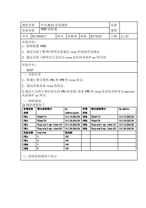
四、实验步骤VRRP是网关冗余协议,是保护网关的配置思路如下:1,在交换机上配置vlanif的接口地址2,在交换机的vlanif接口下配置vrrp3,vlan10的主用网关在SWA上,vlan20的主用网关在SWB上配置的具体步骤如下:1,在交换机SWA和SWB上创建vlanif10和vlanif20的接口,并按照规划配置相应的ip地址<SWA>system-view[SWA]interface Vlanif 10 创建三层接口[SWA-Vlanif10]ip address 10.1.10.253 24 配置IP地址[SWA-Vlanif10]quit[SWA]interface Vlanif 20 创建三层接口[SWA-Vlanif20]ip address 10.1.20.253 24 配置IP地址<SWB>system-view[SWB]interface Vlanif 10 创建三层接口[SWB-Vlanif10]ip address 10.1.10.252 24 配置IP地址[SWB-Vlanif10]quit[SWB]interface Vlanif 20 创建三层接口[SWB-Vlanif20]ip address 10.1.20.252 24 配置IP地址2,配置vrrp,在SWA上设置vrrp vrid 1的优先级为120,让SWA成为vlan10的网关。
在SWB上设置vrrp vrid 2 的优先级为120,让SWB成为vlan20的网关。
同时设置主用网关的抢占时延为20S。
具体配置如下:<SWA>system-view[SWA]interface Vlanif 10[SWA-Vlanif10]vrrp vrid 1 virtual-ip 10.1.10.254配置vrrp组1的虚IP [SWA-Vlanif10]vrrp vrid 1 priority 120配置vrrp组1的优先级[SWA-Vlanif10]vrrp vrid 1 preempt-mode timer delay 20配置抢占时延[SWA-Vlanif10]quit 退出三层接口配置模式[SWA] interface Vlanif 20[SWA-Vlanif20]vrrp vrid 2 virtual-ip 10.1.20.254配置vrrp组2的虚IP [SWA-Vlanif20]quit 退出三层接口配置模式[SWA]quit 退出配置模式<SWA>save 保存当前配置<SWB>system-view[SWB]interface Vlanif 10[SWB-Vlanif10]vrrp vrid 1 virtual-ip 10.1.10.254[SWB-Vlanif10]quit[SWB] interface Vlanif 20[SWB-Vlanif20]vrrp vrid 2 virtual-ip 10.1.20.254[SWB-Vlanif20]vrrp vrid 2 priority 120[SWB-Vlanif20]vrrp vrid 2 preempt-mode timer delay 20[SWB-Vlanif20]quit[SWB]quit<SWB>save3,查看vrrp组的状态是否符合我们的规划4,将SWA关闭,查看一下SWB的vrrp状态,是否切换为vrrp vrid 1 的主用网关5,然后在将SWA开启,查看一下SWB的vrrp状态,是否重新成为vrrp vrid 1的备用网关可以看到vrrp进行了切换,主用网关依然是SWA。
配置VRRP

1. 组网需求主机A 把交换机A 和交换机B 组成的VRRP 备份组作为自己的缺省网关,访问Internet 上的主机B。
VRRP 备份组构成:备份组号为1虚拟路由器的IP 地址为202.38.160.111交换机A 做Master交换机B 做备份交换机,允许抢占2. 组网图3. 配置步骤(1) 配置交换机A:# 配置VLAN2。
<LSW-A> system-view[LSW-A] vlan 2[LSW-A-vlan2] port Ethernet 1/0/6[LSW-A-vlan2] quit[LSW-A] interface Vlan-interface 2[LSW-A-Vlan-interface2] ip address 202.38.160.1 255.255.255.0[LSW-A-Vlan-interface2] quit# 使备份组的虚拟路由器的IP 地址可以被ping 通。
[LSW-A] vrrp ping-enable# 创建一个备份组。
[LSW-A] interface vlan 2[LSW-A-Vlan-interface2] vrrp vrid 1 virtual-ip 202.38.160.111# 设置备份组的优先级。
[LSW-A-Vlan-interface2] vrrp vrid 1 priority 110# 设置备份组的抢占方式。
[LSW-A-Vlan-interface2] vrrp vrid 1 preempt-mode(2) 配置交换机B:# 配置VLAN2。
<LSW-B> system-viewSystem View: return to User View with Ctrl+Z.[LSW-B] vlan 2[LSW-B-Vlan2] port Ethernet 1/0/5[LSW-B-vlan2] quit[LSW-B] interface Vlan-interface 2[LSW-B-Vlan-interface2] ip address 202.38.160.2 255.255.255.0[LSW-B-Vlan-interface2] quit# 使备份组的虚拟路由器的IP 地址可以被ping 通。
H3C3600交换机配置及说明文档--21-VRRP命令

Interface
: Vlan-interface10
VRID
:1
CheckSum Errors
:0
Version Errors
:0
VRID Errors
:0
Advertisement Interval Errors : 0
IP TTL Errors
:0
Auth Failures
:0
Invalid Auth Type
1.1.4 vrrp method
【命令】 vrrp method { real-mac | virtual-mac } undo vrrp method
【视图】 系统视图
:0
Auth Type Mismatch
:0
Packet Length Errors : 0
Address List Errors
:0
Become Master
:2
Priority Zero Pkts Rcvd
:0
Advertise Rcvd
:0
Priority Zero Pkts Sent
:1
Invalid Type Pkts Rcvd: 0
【举例】 # 清除交换机上 VRRP 的统计信息。
<H3C> reset vrrp statistics
1.1.3 vrrp authentication-mode
【命令】 vrrp authentication-mode authentication-type authentication-key undo vrrp authentication-mode
当认证方式为 simple 和 md5 时,必须设置认证字。 这条命令是为一个接口上的所有 VRRP 备份组设置认证方式和认证字,这是由于协 议规定一个接口上的备份组应当使用相同的认证方式和认证字。另外,加入同一备 份组的成员也应该设置相同的认证方式和认证字。
VRRP配置命令

undo vrrp method
【视图】
系统视图
【参数】
real-mac:在VRRP进行备份的时候采用交换机路由接口的实际MAC地址和备份组的虚拟IP地址对应。
virtual-mac:在VRRP进行备份的时候采用虚拟MAC地址和备份组的虚拟IP地址对应。
【描述】
vrrp method命令用来设置备份组虚拟IP地址和MAC地址的对应关系:使用路由接口的实际MAC地址对应备份组虚拟IP地址或者采用虚拟MAC地址对应备份组虚拟IP地址,undo vrrp method命令用来恢复地址对应的缺省对应关系。
VRID
Virtual router 的VRID
Adver.Timer
广播报文发送时间
Admin Status
Virtual router的控制状态
State
Virtual router运行状态
Config Pri
配置的优先级
Run Pri
运行的优先级
1.1 VRRP配置命令
1.1.1 debugging vrrp
【命令】
debugging vrrp { state | packet }
undo debugging vrrp { state | packet }
【视图】
用户视图
【参数】
state:VRRP的状态调试开关;
缺省情况下,备份组被设置为抢占方式,延迟时间为0秒。
如果需要优先级高的交换机能够主动抢占成为MASTER,就需要将这台交换机设置为抢占方式。如果需要将抢占的时间延长,还可以设置延迟时间。当设置为不抢占时,延迟时间会自动被置为0秒。
vrrp实验配置

VRRP实验一、VRRP介绍VRRP(Virtual Router Redundancy Protocol,虚拟路由器冗余协议)是一种容错协议,其目的是利用备份机制来提高路由器(或三层以太网交换机)与外界连接的可靠性。
它是为具有多播或广播能力的局域网(最明显的例子就是以太网)而设计的,由IETF提出,目前应用比较广泛。
通常,一个局域网内的所有主机都会设置一条缺省路由以指明缺省网关,主机发出的那些目的地址不在本网段的报文将通过该缺省路由发往缺省网关,从而实现了局域网内各主机与外部网络的通信。
然而,当作为缺省网关的路由器与外部网络相连的通信链路出现故障后,本网段内所有以该网关为缺省路由下一跳的各主机将被迫中断与外部网络的通信。
VRRP就是为解决上述问题而提出的。
VRRP运行于局域网的多台路由器上,它将这几台路由器组织成一台“虚拟”路由器,或称为一个备份组(Standby Group)。
在这个备份组中,有一个活动路由器(被称为Master)和一个或多个备份路由器(被称为Backup)。
活动路由器将实际承担这个“虚拟”路由器的工作任务(如负责转发各主机送给“虚拟”路由器的报文),而备份路由器则作为活动路由器的备份。
在运行的时候,这个“虚拟”路由器拥有自己的“虚拟”IP地址(该地址可以和备份组内某个路由器的接口IP地址相同),备份组内的路由器也有自己的IP地址。
但是,由于VRRP只在路由器或以太网交换机上运行,所以对于该网段上的各主机来说,这个备份组是透明的,它们仅仅知道这个“虚拟”路由器的“虚拟”IP地址,而并不知道Master以及Backup 的实际IP地址,因此它们将把自己的缺省网关地址设置为该“虚拟”路由器的“虚拟”IP 地址。
于是,本局域网内的各主机就通过这个“虚拟”路由器来与其它网络进行通信。
而实际上,它们是通过Master在与其它网络进行通信。
而一旦备份组内的Master发生故障,Backup将会接替其工作,成为新的Master,继续为本局域网内的各主机提供服务,从而保障本局域网内的各主机可以不间断与外部网络的通信。
- 1、下载文档前请自行甄别文档内容的完整性,平台不提供额外的编辑、内容补充、找答案等附加服务。
- 2、"仅部分预览"的文档,不可在线预览部分如存在完整性等问题,可反馈申请退款(可完整预览的文档不适用该条件!)。
- 3、如文档侵犯您的权益,请联系客服反馈,我们会尽快为您处理(人工客服工作时间:9:00-18:30)。
交换机VRRP配置1. VRRP原理请参考相关文档。
VRRP协议将系统中多台路由器组成VRRP组,该组中拥有一个虚拟默认网关地址。
但在任何时刻,一个组内只有控制虚拟网关地址的路由器是活动路由器(Master),由它来转发数据包。
如果活动路由器发生了故障,它将选择一个优先权最高的冗余备份路由器(Backup)来替代活动路由器。
由于网络内的终端配置了VRRP虚拟网关地址,发生故障时,虚拟路由器没有改变,主机仍然保持连接,网络将不会受到单点故障的影响,这样就较好地解决了网络中路由器切换的问题。
(图1)一个简单的冗余交换网络如上图所示,VRRP运行在同一局域网的路由器A和路由器B两个路由器上,分别作为主路由器(端口地址为192.168.1.2/24)和备份路由器(端口地址为192.168.1.3/24)。
同时,利用VRRP协议将上述两个路由器组成一个虚拟路由器(端口地址为192.168.1.1/24)。
在主机子网上对用户机器配置默认网关192.168.1.1/24。
由此,对于用户主机来说,只需配置一个透明的默认网关,而至于由哪个路由器来负责扮演网关,或者说任意一个路由器发送故障都不会影响该主机与该网关的通信。
2. 在交换机上配置VRRP备份组为了将客户机连接到Internet,在连接客户机的三层设备上,还需配置一个端口用以与上层路由器相连,同时在该三层设备上必须配置一个默认路由(default route)表,指明该三层设备的默认网关是上层路由器,以此实现客户机与外部Internet的通信访问。
因此,保障网络关键应用的首要任务是保证这些客户端与上层路由器的通信可靠和冗余。
可以看出,若使用如上图的简单的VRRP交换网络,虽然能保证客户机与网关的网络通信,但无法进一步实现客户机与外部网络的通信冗余。
为此如下图所示,客户机通过二层交换机分别连接到两个三层设备,然后这两个设备又通过一个交换机(DI-7000内置)与上层路由器建立连接。
(图2)其中,DES-3828-A上配置两个端口,分别是192.168.1.1/24,192.168.0.2/24。
同时,在DES-3828-B上也相应地配置两端口:192.168.1.2/24,192.168.0.3/24。
在两台DES-3828 上分别启动两个虚拟路由器组——VRRP1 和VRRP2,它们都有两个interface。
其中,VRRP1 的interface 分别为192.168.1.1(Master)和192.168.1.2(Backup),用于客户机的网关通信;而VRRP2的interface分别为192.168.0.3(Master)和192.168.0.2(Backup),用于与上层路由器通信,保证对外网的通信访问。
与图1 所示相比,图2 的网络结构除了原有的客户机与三层设备的VRRP 组(VRRP1 )外,还增加了用于三层设备与上层路由器相联的VRRP 组(VRRP2),以此保证客户机与上层路由器的通信冗余。
其中,针对不同的网络情况,具体的通信分析如下:1、在正常(即Master 处于工作状态)情况下,客户机是通过Mater与外网进行网络通信,通信链路是:客户机<——> 交换机<——>Master<——> 交换机(DI-7000 内置)<——> 上层路由器<——>INTERNET 。
2、当Master 发生故障时,Backup 则会通过VRRP接管网关,此时的通信链路为:客户机<——> 交换机<——>Backup<——> 交换机(DI-7000 内置)<——> 上层路由器<——>INTERNET 。
如上所述,在如图2 的网络设计中,任意一个三层设备的故障或者是物理链接的失败,都可以通过VRRP 协议来快速地恢复通信,由此保障客户机与外网的通信访问,实现网络关键应用的高可靠性3. DES-3828-A配置# VLAN,建立2 个VLAN,并添加接口config vlan default delete 1-28 create vlan v10 tag 10 config vlan v10 add untagged 13-24 create vlan v20 tag 20 config vlan v20 add untagged 1-12 # IP,配置两个接口IP 地址create ipif if10 192.168.0.2/24 v10 state enablecreate ipif if20 192.168.1.1/24 v20 state enable# ROUTE,建立到上层路由器的默认路由create iproute default 192.168.0.1# VRRP,建立两个VRRP 组create vrrp vrid 1 ipif if20 ipaddress 192.168.1.254 state enable priority 120 //建立VRRP1,设置虚拟IP地址为192.168.1.254,并将此路由器设置为VRRP1中的Master.vrid <vrid 1-255> -输入一个1到255之间的数值来对交换机上的VRRP组进行唯一性识别。
所有加入该组的路由器必须被分配相同的VRID值,该值必须与交换机上设置的其他VRRP组的值不同。
ipif <ipif_name 12> -输入之前配置的想要创建VRRP条目的IP接口名,该IP接口必须被分配到交换机上的一个VLAN。
ipaddress <ipaddr> -输入将要分配给VRRP路由器的虚拟IP地址。
该虚拟IP地址也是将被静态分配给终端主机。
state [enable | disable] -用于在交换机上启用和禁用VRRP路由器。
priority <int 1-254> -输入一个1到254之间的数值来表示路由器的优先级,较高优先级将增加该路由器变为组中主路由器的可能性。
较低的优先级将增加该路由器变成备份路由器的可能性。
两个VRRP路由器的优先级相同,物理IP地址最高的路由器作为主路由器。
优先级默认值为100。
0优先级保留为特殊用途使用,当虚拟IP地址被设置为路由器接口的真实IP 地址时,此VRRP路由器将被设置为拥有最高的优先级255.create vrrp vrid 2 ipif if10 ipaddress 192.168.0.254 state enable priority 100 //建立VRRP2,设置虚拟IP地址为192.168.0.254,并将此路由器设置为VRRP2中的Backup.enable vrrp//启用交换机的全局VRRP功能DES-3828-B配置# VLAN config vlan default delete 1-28 create vlan v10 tag 10 config vlan v10 add untagged 1-12 create vlan v20 tag 20 config vlan v20 add untagged 13-24# IP create ipif if10 192.168.0.3/24 v10 state enable create ipif if20192.168.1.2/24 v20 state enable# ROUTE create iproute default 192.168.0.1# VRRP create vrrp vrid 1 ipif if20 ipaddress 192.168.1.254 state enable priority 100 //建立VRRP1,设置虚拟IP地址为192.168.1.254,并将此路由器设置为VRRP1中的Backup.create vrrp vrid 2 ipif if10 ipaddress 192.168.0.254 state enable priority 120 //建立VRRP2,设置虚拟IP地址为192.168.0.254,并将此路由器设置为VRRP2中的Master. enable vrrp注:建立VRRP组的步骤也可分为2步:1 1. create vrrp vrid 1 ipif if20 ipaddress 192.168.1.254 state enable2 2. config vrrp vrid 1 ipif if20 state enable priority 120为了使故障切换时间更快,可以将Master、Backup的优先级设置为253、254给VRRP组配置critical_ip该IP地址为虚拟路由器连接互联网和其他关键网络连接提供最直接的路由。
这必须是网络上真实设备的真实IP地址。
如果虚拟路由器与该IP地址的连接出现故障,虚拟路由器将被自动禁用。
将从VRRP组备份路由器中选择一台备份路由器作为新的主路由器。
例如:create vrrp vrid 1 ipif if20 ipaddress 192.168.1.254 state enablepriority 120 advertisement_interval 1 preempt true critical_ip192.168.0.1 critical_ip_state enableadvertisement_interval<int 1-255> -输入一个时间间隔值,单位为秒,以便发送VRRP信息数据包。
该值必须与参加了同一个VRRP组的所有路由器一致。
默认为1秒。
preempt[true\false] –在VRRP 运行过程中,Master 定期发送VRRP 通告信息,Backup 将侦听Master 的通告信息。
当Backup 在Master 失效间隔时间内没有接收到通告消息时,Backup 认为Master 失效,并接替后者角色。
VRRP preempt 模式指原先的Master 从故障中恢复并接入到网络中,它将夺回自己的角色,否则仍然保持Backup 状态。
在该设置必须与所有参与同一个VRRP 组的所有路由器一致。
默认设置为true 。
DI-7000路由器配置:客户端IP地址信息配置:VRRP信息检测:DES-3800-A:admin#show vrrpCommand: show vrrpGlobal VRRP : EnabledNon-owner response PING: DisabledInterface Name : if10Authentication type : No AuthenticationVRID : 2Virtual IP Address : 192.168.0.254Virtual MAC Address : 00-00-5E-00-01-02Virtual Router State : BackupState : EnabledPriority : 100Master IP Address : 192.168.0.3Critical IP Address : 0.0.0.0Checking Critical IP : DisabledAdvertisement Interval : 1 secs Preempt Mode : True Virtual Router Up Time : 3457 centi-secsInterface Name : if20Authentication type : No AuthenticationVRID : 1Virtual MAC Address : 00-00-5E-00-01-01Virtual Router State : MasterState : EnabledPriority : 120Master IP Address : 192.168.1.1Critical IP Address : 0.0.0.0Checking Critical IP : DisabledAdvertisement Interval : 1 secs Preempt Mode : True Virtual Router Up Time : 3457 centi-secsTotal Entries: 2DES-3800-B:admin#show vrrpCommand: show vrrpGlobal VRRP : EnabledNon-owner response Ping: DisabledInterface Name : if10Authentication type : No AuthenticationVRID : 2Virtual IP Address : 192.168.0.254Virtual MAC Address : 00-00-5E-00-01-02Virtual Router State : MasterState : EnabledPriority : 120Master IP Address : 192.168.0.3Critical IP Address : 0.0.0.0Checking Critical IP : DisabledAdvertisement Interval : 1 secsPreempt Mode : True Virtual Router Up Time : 2396 centi-secsInterface Name : if20Authentication type : No AuthenticationVRID : 1Virtual MAC Address : 00-00-5E-00-01-01Virtual Router State : BackupState : EnabledPriority : 100Master IP Address : 192.168.1.1Critical IP Address : 0.0.0.0Checking Critical IP : DisabledAdvertisement Interval : 1 secs Preempt Mode : True Virtual Router Up Time : 2607 centi-secsTotal Entries: 2当DES-3828-B 宕机后DES-3828-A 信息输出如下:DES-3800:admin#show vrrp Command: show vrrpGlobal VRRP : EnabledNon-owner response PING: DisabledInterface Name : if10Authentication type : No AuthenticationVRID : 2Virtual IP Address : 192.168.0.254Virtual MAC Address : 00-00-5E-00-01-02Virtual Router State : MasterState : EnabledPriority : 100Master IP Address : 192.168.0.2Critical IP Address : 0.0.0.0Checking Critical IP : DisabledAdvertisement Interval : 1 secs Preempt Mode : True Virtual Router Up Time : 3457 centi-secsInterface Name : if20Authentication type : No AuthenticationVRID : 1Virtual IP Address : 192.168.1.254Virtual MAC Address : 00-00-5E-00-01-01Virtual Router State : MasterState : EnabledPriority : 120Master IP Address : 192.168.1.1Critical IP Address : 0.0.0.0Checking Critical IP : DisabledAdvertisement Interval : 1 secs Preempt Mode : True VirtualRouter Up Time : 3457 centi-secsTotal Entries: 2此时客户机根本感觉不到DES-3828-B出现了问题,与Internet的通信仍然很通畅。
