ECI-CFV英文版诊断软件安装使用说明书-20140305
(1).欧洲福特诊断软件使用说明
力控制系统) 5、ACM:Audio Control Module(音频控制模块) 6、BCM:Body Control Module(车身控制模块) 7、EPS:Electronic Controlled Power Steering(电子控制动力转向) 8、GEM:Generic Electronic Module(通用电子模块) 9、IC:Instrument Cluster(仪表板) 10、NAV:Navigation Controller(导航控制器) 11、PAM:Parking Aid Module(驻车辅助模块) 12、RCM:Restraint Control Module(辅助限制控制模块) 13、EATC:Electronic Automatic Temperature Control(电子自动温度控制) 14、HVAC:Heating Ventilation Air Conditioning(暖风空调) 15、PATS:Passive Anti Theft System(被动防盗系统) 16、ECU: Electronic Control Unit(电子控制单元)
2.2.1 询问系统
诊断程序通过与 ECU 交互通信,分析 ECU 响应的数据,自动的显示出被测试车辆的可测 电控制单元列表.大部分车辆都不需要客户根据 vin 码,车型,年款,发动机号等信息选择菜单进 入, 使得车辆诊断更易操作.
下面以 Focus C-MAX 车型 1.6L 为例进行测试,点击”询问系统”菜单,提示客户选用正确 的诊断接头类型.(图 4)
2.2.1 询问系统..................................................................................................................8 2.2.2 快速诊断................................................................................................................12 2.2.3 手动菜单................................................................................................................15 2.3 诊断功能菜单介绍..........................................................................................................20 2.3.1 读故障码...............................................................................................................22 2.3.2 清除故障码...........................................................................................................25 2.3.3 读数据流...............................................................................................................26 2.3.4 动作测试...............................................................................................................31 2.3.5 特殊功能...............................................................................................................34
中国机车远程诊断与监测系统车载子系统(CMD)安装使用说明书

序号 1A 2A
状态/含义 亮/灭:12V 输出正常/异常 亮/灭:74V/110V 输入正常/异常
2.4.2
主处理板共有 12 个状态指示灯,指示灯定义见表 3。
表3 主处理板指示灯定义 序号 1B 2B 3B
指示灯 电源 工作/下载 通信
含义 DC 5 V 电源输 入 工作状态 与主处理器板以 太网数据通信
颜色 绿 绿 绿
2.5
2.5.1
单板指示灯定义 B(8 轴车的从机)
电源板共有 4 个状态指示灯,指示灯定义见表 9。
表9 电源板指示灯定义 序号 1B 2B 状态/含义 亮/灭:5V 输出正常/异常 亮/灭:表示故障/正常
2
1
序号 1 2 3 4 5 6 7 8 9 10
产品配置清单
代号
SWX13009-100-000
名称
机车车载综合信息监测装置
数 量
1台 (套) 1个 1套 1套 1个 1个 6个 6个 6个 6个 2套
备注
简称: “LDP” (8 轴车包含主机和 从机)
合格证 安装支架 电缆 北斗通信天线 组合机车天线
2.4.5
无线通信板共有 8 个状态指示灯,指示灯定义见表 6。
表6 无线主控板指示灯定义 序号 1B 状态/含义 闪/ 亮/ 灭:北斗/GPS 定位有效/ 数据接收通道正常/故障 闪/亮/灭:正通过 3G 传输数据 /3G 联网成功 /故障或无信号 闪/亮/灭:正通过北斗传输短报 文 / 北斗信号良好 / 故障或无信 号
2.4.4
网络接口板共有 8 个状态指示灯,指示灯定义见表 5。
五合一笔记本诊断卡 使用说明
五合一笔记本诊断卡五合一笔记本诊断卡使用说明五合一笔记本诊断卡是三合一笔记本诊断卡(VIP)升级版,支持笔记本电 脑 MiniPCIe, MiniPCI, LPC, ELPC 和 I2C 笔记本电池接口总线架构。
该笔记本 诊断卡采用四层 PCB 设计,信号稳定性好,兼容性好,使用方便,是笔记本电脑 维修的必备工具。
一:系统主要组成部分 二:诊断卡的 MiniPCIe 接口 三:诊断卡的 MiniPCI 接口 四:诊断卡的 LPC 接口 五:诊断卡的 ELPC 接口(ASUS 专用诊断接口) 六:诊断卡的 I2C 接口(联想专用笔记本电池接口) 七:诊断卡的显示接口和信号指示接口 八:诊断卡的出错信息 九:问题和解答版权所有:任何人未经允许,不得擅自复制,销售该笔记本诊断卡。
一:系统主要组成部分1五合一笔记本诊断卡① ② ③ ④ ⑤ ⑥ ⑦ ⑧诊断卡 MiniPCIe 接口 诊断卡 MiniPCI 接口 诊断卡 LPC 接口 诊断卡 ELPC 接口 诊断卡 I2C 接口(笔记本电池接口) 诊断卡的显示接口:两个七段数码管和两个信号指示灯 诊断卡的专用主芯片:用于处理诊断卡的信号 诊断卡的测试接口: 仅用于出厂前的检测,用户请勿使用。
二:诊断卡的 Mini PCI-E 接口 Mini PCI-E 是笔记本主板正在逐渐使用的新型接口。
比较于 Mini PCI 接口, Mini PCI-E 接口占用更少的空间。
该诊断卡使用 Mini PCI-E 接口的下列管脚: PIN-8, PIN-10, PIN-12, PIN-14, PIN-16, PIN-17, PIN-19。
当前,由于不是所 有的笔记本厂家都支持该管脚定义标准,所以并非目前所有笔记本主板都支持该 接口。
经测试,最近的联想,惠普, 富士通,东芝,神州,宏基,英业达,广达 等笔记本主板能够支持该接口。
对于不支持该接口的笔记本主板,该接口将无法 正常使用。
CA公司光伏I-V曲线测试仪用户手册说明书

1. 警告您刚刚购买了法国CA公司的I-V TRACER FTV200 光伏I-V曲线测试仪,我们非常感谢您对我司产品的信任!请在使用仪器前仔细阅读以下说明。
遵守安全保护措施。
仪器中符号的意义如下:注意,危险!请查阅用户手册。
CE标志确保仪器符合欧洲标准。
仪器完全受双重绝缘或加强绝缘的保护。
垃圾桶上打叉的符号意思是,根据WEEE指令2002/96/EC,该产品的电子配件在废弃时必须进行回收再利用。
USB接口。
警告!测试点适配器使用:当您连接测试点时,请核实并确保装置或电路上不带电。
应该无导电部分外露。
连接测试点至装置或电路,仅与以下列出的测试附件相连:导电部分2. 安全保护措施为了正确使用仪器,以下的防护措施是强制性的。
不遵守以下指示,可能导致触电、爆炸、火灾等危险。
的意思为,警告!使用配件前请阅读说明。
说明前加上这个标志,未按解释执行,可能导致人身事故或配件和设备的损坏。
如果不正确地使用仪器,安全性将不能保证,可能导致危险的测试环境。
用户不可自行更换内部的可充电电池。
需要更换内部电池,请联系法国CA在华子公司。
任何系统连接本仪器的安全性责任,由接入系统之人承担。
为了您的安全,请仅使用仪器附带的导线和配件:它们符合IEC 61010-031(2002)的标准。
当传感器或配件低于仪器的安全等级,降额必须应用于整个设备。
每次使用前,确保导线、接线盒及配件完全符合工作条件。
每个绝缘受损的(哪怕是局部的)导线、传感器或配件,都必须送修或是报废。
进行测量时请不要使用主电源供电。
主电源仅用于为内部电池充电,仅在仪器关闭时进行充电。
遵守使用环境。
个人防护设备的使用与仪器使用环境的推荐防护设备一致。
仪器能使用于CAT III 600V 或CAT II 1000V的设备。
请勿使用于电压或安全等级更高的系统。
要更换内部电池,请仅联系法国CA在华子公司。
这些部件有特殊的安全防护装置,使用非原配的备件可能导致严重的人员或设备的损伤事故。
ESI[tronic] 2.0 多功能车辆诊断软件说明书
![ESI[tronic] 2.0 多功能车辆诊断软件说明书](https://img.taocdn.com/s3/m/18726f92c0c708a1284ac850ad02de80d4d80608.png)
Diagnostic SolutionsESI[tronic] 2.0ESI[TRONIC] 2.0 SOFTWARE SOLUTION:MULTIFUNCTIONALITY FOR VEHICLE DIAGNOSISThe multi-brand vehicle diagnostic software provides easy usage, fast access and broad vehicle coverage – this makes ESI[tronic] 2.0 a user-friendly, multifunctional information tool.Today one expects more than just control unit diagnostics from workshop software, no matter if it concerns passenger or commercial vehicles. Intelligent troubleshooting, support for rapid repair and maintenance according to manufacturer specifications are the new standard in the diagnostics segment. All these requirements can be met with the ESI[tronic] 2.0. The efficient control unit diagnosis from Bosch guides you through the troubleshooting process step-by-step. With ESI[tronic] 2.0, all the necessary information on the vehicle regarding maintenance and service is provided instantly. ESI[tronic] 2.0 contains the newest data on all standard vehicle types thanks to regular patches and thus allows you to stay up-to-date with regular Bosch-validated software updates.The integrated solution Experience-based repair – Known Fixes allows quick access to known faults and proposed solutions at the same time repair solutions are required. Fast and reliable repairs are the basis for excellent results and high customer satisfaction.④Multibrand vehicle control unit diagnostic software: ESI[tronic] 2.0 is already used in every third independentworkshop in Europe④Worldwide great coverage for passenger cars, bikes, LCVs, trucks, buses and trailers in breadth and depth④Over 90.000 vehicles from more than 150 brands covered④Advance adjustment and programming functionalities④Vehicle identification through KBA key or VIN enables efficient analysis on the average in 20 seconds④All necessary data for repair and maintenance according to manufacturer specifications presentedin a convenient, easy and understandable manner④Supports the workshop networking concept Connected Repair (CoRe) for higher efficiency and effectiveness④Always up-to-date with regular online updates:takes place in the background, workshops can use the software simultaneously without limitation④High value and benefit: additional licenses for little money on multiple devicesDiagnostic software for maintenance and repair withcomprehensive vehicle coverage: with its modular structure, ESI[tronic] 2.0 ensures that you can always find the best repair solution for your daily business.Must-have for every professional in the workshop:SD ④ Vehicle diagnosisSIS④Vehicle troubleshooting instructions EBR ④Experience-based repair – Known Fixes M ④Vehicle mechanics and maintenance schedules P ④ Comfort systems wiring diagrams④ Technical hotline / car repair hotlineCore ModulesUse the latest diagnostic data for passenger car, bike, van and truck systems for all necessary service tasks.►Service task menu for time-saving experts:you can find shortcuts to all service-relevant operations►Flight recorder function to detect and analyze complexintermittent faults►Protocols for documentation and handing informationabout the vehicle provided to customers►Advanced coding and adjustment functionalities►Worldwide greatest coverage for all control units:from identification to reading / deleting error memory,actual values, actuators, function tests, adjustments /settings and some special functions for individual andprofessional service proceduresThe troubleshooting instructions reliably guide you step-by-step to the cause of the fault. All of the information required for maintenance and service is available at the vehicle immediately.► A system-based troubleshooting database hand-crafted by Bosch experts►SIS/CAS complete system description and step-by-step testing including OE values and real-time comparison with VCI multimeter measurementsTroubleshooting instructions contain the following information:►Installation positions and removal / installation instructions►Overviews for the vehicle such as data bus overviews►System tests of almost any component in the car►Wiring diagram►Control unit terminal assignment►Self-diagnosis overview (including actual value description and fault code tables)►System identification►Service interval resetFind the right solution within seconds, even for challenging troubleshooting cases. EBR includes data on specific errors repeatedly occurring on certain vehicle models.In case a known error is detected during the diagnosis, ESI[tronic] 2.0 recommends the technician a repair solution which has already been proven to be a good remedy.►Contains repair instructions for frequently occurring faults;even faster and easier solutions compared to classicaltroubleshooting►Repair instructions generated by the experienced Boschauthoring team and validated thanks to the expertise of theworldwide Bosch diagnostic community.►First online information type which requires an internetaccess to ensure that the workshop is always provided withthe latest content.►Already over 700.000 real-life use cases / vehiclecombinations – and the database is growing day by day!►Optimal time savings: The free text search allows you tosearch for error codes, symptoms, and even components, aswell as faults without error codes stored.►Common structure of the repair instructions facilitates the repair process.►The feedback function at the bottom of each repair instruction allows you and other ESI[tronic] 2.0 diagnostic experts to categorize and view the ratings of the selected fix.Maintenance information tabs contain service schedules, needed parts, tire size and pressures, wheel alignment data, key programming information, timing belt change instructions, service lights reset instructions and more, with a direct link to diagnostic functions when required.Maintenance tab contains OE service schedules with specific workflows as well as regular maintenance information. This ensures that vehicle manufacturer warranties are maintained.►Service schedule operations can be filled in directlyvia the tool and the reports edited or initially printed► A vast majority of the day-to-day operations iscontained in a single tab►Maintenance also contains instructions with thefollowing information:►Service Illustrations►Service Indicator►Exhaust Gas Treatment, Diesel Engine►VIN Plate Location►Technical Data►Timing Gears►Auxiliary Drive BeltsGiant data base including wiring diagrams for all important systems such as engine management, comfort systems and bus systems for optimal efficiency.►Positions and designations of each item areclearly referenced. They are selectable from boththe component list and directly from the diagramitself.►The last selected diagram remains stored. It isautomatically recalled when the end user performsother functions and returns to the Circuit Diagramstab.►Integrated search and automated highlighting►General Features:ground points, full screen mode button andshortcut to line colorsOur technical hotline has many years of experience in the workshop daily business and can help you in the diagnosis and repair of cars and commercial vehicles. Thanks to the comprehensive expertise in automotive engineering, even complex system problems can be solved quickly and competently. In case you do not have any solution, our experts will be able to perform remote diagnostics on your computer and solve the problem together with you.►Benefits for your workshop:►Comprehensive competence of Bosch in automotive systems engineering►Manufacturers and expertise in mechanical, electrical and electronic systems in the automotive sector across all brands►Quick problem solving►Constant availability of the latest information►Advantages of the technical hotline at a glance:►Increased efficiency: service and repair become easier and faster►Reduced total costs of ownership: unnecessary use of personnel and workshop equipment avoided►Customer satisfaction: high due-date reliability and reduced costs can create a positive image and thus increase customer loyalty►Unburden your workshop manager: your workshop staff gets the support they need to run daily operations smoothly, leaving you to focus on more strategic tasks, e.g. customer satisfaction►Employee satisfaction: fast, competent support motivates your employees in their daily workADDITIONAL SOFTWARE MODULES FOR SPECIALISTS IN THE WORKSHOP►Equipment (Module A)►Bosch diesel spare parts (Module D)►Bosch electric spare parts (Module E)►Component repair instructions (Module K)►Injection pump test data (Module W)►Work values (Module B)►Service calculation (Module S)All the vehicle parts-related modules can be found under the Equipment tab,e.g. work units, estimates, parts catalogues.With ESI[tronic] Bike, a professional diagnosis of motor bikes andscooters is possible. ESI[tronic] Bike offers control unit diagnosis for themost common European and Asiatic bikes, with the diagnosis features ofESI[tronic] 2.0.In addition to control unit diagnosis, ESI[tronic] Truck also contains technicalinformation such as circuit diagrams, service and repair information andinformation on commercial vehicles: trucks, light commercial vehicles, busesand trailers. Model series, power output, engine designation as well as axleconfiguration are included as the basis for a sound diagnosis. Other additionalimportant diagnosis functions are available: Reading / deleting error codes,selecting actual values, activating actuators, resetting service intervals, andteaching in components.More and more vehicle manufacturers are using a new diagnostic interface based on Ethernet, also known as DoIP (Diagnostics over Internet Protocol). The advantage of it is up to 100 times faster data transfer compared to previous technologies, which were mostly used for flashing the control unit. In addition to the speed advantage, ethernet-based diagnosis offers a secure and stable data transfer. It is not unlikely that in the near future, more and more manufacturers will use Ethernet for regular vehicle diagnostics as well. Being prepared for this development, the new diagnostic tester from the Bosch KTS series supports Ethernet as well as conventional vehicle interfaces. This means you are ready for the requirements of tomorrow with an intelligent solution from today.Most European vehicle manufacturers have already equipped their currentvehicle models with such new, Ethernet-based diagnostic interfaces. The Volvo XC90 is the first vehicle on the market allowing a complete diagnosis only by means of the Ethernet interface.In the future, basic diagnoses will still be possible via CAN, but comprehensive diagnostics and the flashing of control units will only be done via the Ethernet interface.ESI[tronic] 2.0 always supports the latest technology standards with regard to DoIP and is therefore the promising solution for every workshop in the future. The software automatically detects when to activate the Ethernet interface.Thanks to regular updates, automotive workshops can always be sure to have the latest data for all common vehicle types at their disposal. Whenever a Bosch diagnostic device connects to the internet, all updates will download automatically in the background while the device is still in use.► Full online download option for ESI[tronic] 2.0► High time-saving possibility thanks to easier installation process► Download takes place in the background – ESI[tronic] 2.0 can be used simultaneously without limitation ► Store the ESI[tronic] 2.0 on a USB stick and then simply drag & drop it to an offline PC ► If an internet connection is not available, DVDs will remain as a proven update optionCAS[plus] in ESI[tronic] 2.0 can be used to quickly switch between the information modules for a convenient, fast and efficient daily diagnostic work environment:Additionally, extended CAS[plus] functionality provides a seamless integration of the multimeter and oscilloscope ofKTS.System OverviewTroubleshooting instructions (Module SIS)Vehicle diagnosis (Module SD)Mechanics & maintenance schedules (Module M)In consideration of expanding workshop activities, no additional software licenses are required for the hardware. The KTS can thus be used for several PCs in combination with the installed ESI[tronic] 2.0 software.Your benefit: the comprehensive ESI[tronic] 2.0 solution on several devices for a one-time purchase.The following operating systems are recommended for ESI[tronic] 2.0:► Windows 7 (Home Premium 32+64 bit, Business 32+64 bit) ► Windows 8 (32+64 bit) ► Windows 10 (32+64 bit)ESI[tronic] 2.0 supports the Bosch workshop connection concept known as Connected Repair. Thanks to regular updates, automotive workshops can be sure to always have the latest data of all common vehicles types at their disposal.In other words, the software is linked to almost the entire Bosch Automotive Solutions product portfolio (such as KTS, DCU, FSA, BEA, EPS, DAS, HTD), as well as parts catalogues and repair workflows.ESI[tronic] 2.0 goes hand in hand with our diagnostic hardware for efficiency and effectiveness in your daily work.V 1.0, 19.01.2018, C o n t e n t a n d i m a g e s s u b j e c t t o t e c h n i c a l a n d p r o g r a m c h a n g e s .KTS 560 / 590►Modern electronic control unit diagnosis for the highest level of efficiency:can be used in combination with existing PC in the workshop or in combination withDCU 220 or 100.Order number: 0 684 400 560 / 0 684 400 590KTS 350►Advanced diagnostic technology –KTS and DCU with ESI[tronic] 2.0 in one compact and robust deviceOrder number: 0 684 400 350DCU 100►Rugged tablet PC to be used in combination with a Bosch KTS 560 / 590and ESI[tronic] 2.0Order number: 0 684 400 122DCU 220►Multifunctionality at its best: a robust notebook combined with a tablet PC and state-of-the-art technology – for daily workshop challenges together with the KTS 560 / 590Order number:0 684 400 230KTS 460►Diagnostic starter package: DCU 100 and KTS 560Order number: 0 684 400 460KTS 960 & 980►Complete wireless premium package with measuring technology:DCU 220 and KTS 560 or KTS 590Order number: 0 684 400 960 / 0 684 400 980KTS 995►Premium package with additional professional measurement technologyfor vehicle analysis:DCU 220 + KTS 560 and FSA 500Order number: 0 684 400 995。
iMaster NetEco V600R022C00 智能I-V曲线诊断用户手册说明书

iMaster NetEcoV600R022C00Smart I-V Curve Diagnosis User ManualIssue01Date2022-04-11Copyright © Huawei Digital Power Technologies Co., Ltd. 2022. All rights reserved.No part of this document may be reproduced or transmitted in any form or by any means without prior written consent of Huawei Digital Power Technologies Co., Ltd.Trademarks and Permissionsand other Huawei trademarks are the property of Huawei Technologies Co., Ltd.All other trademarks and trade names mentioned in this document are the property of their respective holders.NoticeThe purchased products, services and features are stipulated by the contract made between Huawei Digital Power Technologies Co., Ltd. and the customer. All or part of the products, services and features described in this document may not be within the purchase scope or the usage scope. Unless otherwise specified in the contract, all statements, information, and recommendations in this document are provided "AS IS" without warranties, guarantees or representations of any kind, either express or implied. The information in this document is subject to change without notice. Every effort has been made in the preparation of this document to ensure accuracy of the contents, but all statements, information, and recommendations in this document do not constitute a warranty of any kind, express or implied.Huawei Digital Power Technologies Co., Ltd.Address:Huawei Digital Power Antuoshan HeadquartersFutian,Shenzhen 518043People's Republic of ChinaWebsite:https://About This DocumentPurposeThis document describes the Smart I-V Curve Diagnosis function of the Smart PVManagement System (SmartPVMS), and provides solutions to common faults. Intended AudienceThis document is intended for photovoltaic (PV) plant operating personnel andqualified electricians.Symbol ConventionsThe symbols that may be found in this document are defined as follows.Change HistoryChanges between document issues are cumulative. The latest document issuecontains all updates made in previous issues.Issue 01 (2022-04-11)This issue is the first official release.ContentsAbout This Document (ii)1 Function Description (1)2 Supported Inverter Models (3)3 Smart I-V Curve Diagnosis License Management (8)3.1 License Description (8)3.2 License Management on the SmartPVMS (9)3.3 License Management Through the SmartLogger (11)3.4 License Management on the FusionSolar App or SUN2000 App (13)4 Smart I-V Curve Diagnosis (16)4.1 Smart I-V Curve Diagnosis on the SmartPVMS (16)4.2 Viewing Smart I-V Curve Diagnosis Results on the SmartPVMS (20)5 License Fault Management Table (24)1 Function DescriptionFunctionsSmart I-V Curve Diagnosis allows Huawei inverters to scan PV strings andgenerate an I-V curve, which is then analyzed simultaneously in the Smart PVManagement System (SmartPVMS) to diagnose PV strings and generate alarmsfor faulty PV modules.A large number of PV plant statistics show that PV module quality and faults areimportant factors that affect energy yields. As the PV industry is becoming mature,how to identify faulty PV modules in a convenient and efficient way and how totake appropriate measures to rectify faults are the key to increasing energy yieldsand decreasing investment risks, and are also the development trend of operationand maintenance (O&M).Smart I-V Curve Diagnosis helps scan and diagnose the PV strings connected to aninverter or in an entire PV plant to detect faults and risks and ensure plant safety.In addition, the operation wizard makes O&M easier and faster.Features●Promptly detecting faults and risks of PV modules–All PV modules in a PV plant are scanned periodically through annualinspection, which helps promptly detect faulty PV modules. Timelyprocessing of faulty PV modules helps improve energy yields and preventsfaults from escalating.–PV strings are scanned in real time for any output exceptions to detectfaults and risks.–SmartPVMS analyzes the data simultaneously, which has little impact onenergy yields and ensures high reliability.●Improving the O&M efficiency–Wizard-based remote operation is supported.–I-V curves are analyzed automatically.–Reports are generated automatically.–Rectification suggestions are provided for located faults to improve O&Mquality and efficiency.Key Performance Indicator●Huawei inverter I-V scanning duration (string open circuit to short circuit) < 1s●Huawei inverter I-V scanning resolution: 128 data points●Huawei inverter I-V scanning voltage precision: 0.5%●Huawei inverter I-V scanning current precision: 0.5%●Scanning of a single inverter does not require the inverter to be shut down, soenergy yields will barely be affected.2 Supported Inverter Models3 Smart I-V Curve Diagnosis LicenseManagement3.1 License DescriptionDescriptionSmart I-V Curve Diagnosis can be used only after a license is purchased. Thelicense file for Smart I-V Curve Diagnosis is stored in a Huawei inverter. Theinverter SN uniquely maps to the license.The license for Smart I-V Curve Diagnosis is a fixed-term license. When the licensegoes beyond License Deadline, the system provides a warning asking thecustomer to replace it with a new license.The license can still be used for 60 days (grace period) after the License Deadline.After the Grace period expires, the Smart I-V Curve Diagnosis function will bedisabled.●The SmartPVMS can be used to manage licenses for all inverters in multiple PVplants.●The SmartLogger can be used to manage licenses for all inverters in a PV array.●The FusionSolar app or SUN2000 app can be used to manage the license for asingle Huawei commercial inverter.License Application Procedure1.The customer exports a license application file and sends it to a technicalsupport engineer.2.The technical support engineer transfers the obtained license file to thecustomer.3.The customer imports and loads the license file to an inverter, therebyobtaining the permission to use the Smart I-V Curve Diagnosis function. 3.2 License Management on the SmartPVMS Prerequisites●You have logged in to the SmartPVMS as an installer.●You have created a PV plant and added devices to the PV plant. The devicesare running properly.NO T EThe software version corresponding to the user interface (UI) snapshots in this section isiMaster NetEco V600R022C00SPC110. The UIs could vary with software versions and are forreference only.ProcedureStep 1Choose Plants > Device > Device License Management from the main menu.Figure 3-1 Device license managementStep 2Perform operations according to Table 3-1.Table 3-1 Operations related to license management----End3.3 License Management Through the SmartLogger Prerequisites●You have logged in to the SmartLogger WebUI.●Devices have been added to the SmartLogger and operate normally.●You have logged in as an advanced user, a special user, or the admin user.NO T EThe software version corresponding to the user interface (UI) snapshots in this sectionis SmartLogger3000 V300R001C00SPC060. The UIs could vary with software versionsand are for reference only.ProcedureStep 1Choose Maintenance > License Management on the main menu.Figure 3-2License managementStep 2Perform operations according to Table 3-2.Table 3-2 Operations related to license management----End3.4 License Management on the FusionSolar App or SUN2000 AppPrerequisites●The solar inverter has been connected to the mobile phone installed with theFusionSolar app or SUN2000 app.●You have logged in to the app as an advanced user or an installer user.●The FusionSolar app or SUN2000 app can be used to manage the license for asingle inverter at a time.NO T EThe software version corresponding to the user interface (UI) snapshots in this section isFusionSolar 5.7.011 and SUN2000 3.2.00.014. The UIs could vary with software versions andare for reference only.ProcedureStep 1Choose Maintenance > License management on the main menu.Step 2Tap in the upper right corner of the screen.Figure 3-3 License managementStep 3Tap Load license.Step 4Select the license file to be loaded and confirm the loading.----EndFollow-up ProcedureBefore a device is replaced, the current device license needs to be revoked so thatthe revocation code can be generated and used for applying for a new devicelicense.Step 1Tap Revoke license.Figure 3-4 Revoke licenseStep 2Tap Export revocation code.----End4 Smart I-V Curve Diagnosis4.1 Smart I-V Curve Diagnosis on the SmartPVMS Prerequisites●You have logged in to the SmartPVMS as an installer.●The Smart I-V Curve Diagnosis license has been loaded and is valid.NO T EThe software version corresponding to the user interface (UI) snapshots in this sectionis iMaster NetEco V600R022C00SPC110. The UIs could vary with software versions andare for reference only.ContextTo ensure accurate diagnosis results, you are advised to connect eight or more PVstrings to an inverter.Setting String DetailsStep 1Choose Value-Added Services > Value-Added Services > Smart I-V CurveDiagnosis from the main menu.Figure 4-1 Smart I-V curve diagnosisStep 2Click Configure Strings.Figure 4-2 String managementStep 3Select the plant in the navigation tree on the left, select one or multiple target devices in the device list on the right, and click Next.Figure 4-3 Selecting target devicesStep 4Select a module information template and click Next.Figure 4-4 Selecting a moduleNO T ETemplates for frequently used PV modules have been pre-configured on the SmartPVMS.You can click View details to view detailed module specifications.Step 5Set string parameters as prompted and click Next.Figure 4-5 Setting string parametersNO T EString capacity = Rated power of a PV module x Number of PV modules in a PV string.Step 6Confirm that the string parameters are set correctly, and click Finished.----EndCreating a Smart I-V Curve Diagnosis TaskStep 1Choose Diagnosis Task Management > Add Diagnosis Task.Figure 4-6 Creating a diagnosis taskStep 2Select the plant in the navigation tree on the left, select one or multiple target devices in the device list, and click Next.Figure 4-7 Selecting target devicesStep 3Check whether string information is configured.●If the string information is configured, click Next.●If the string information is not configured, click Configure in the Operationcolumn. In the dialog box that is displayed, configure string details and clickNext.Figure 4-8Configuring String InformationStep 4Set I-V diagnosis task parameters and click Finished.Figure 4-9 Setting task parametersTable 4-1 Diagnosis task parameter descriptionStep 5On the Diagnosis Task Management page, you can view completed andscheduled tasks.Figure 4-10 Viewing completed and scheduled tasks----End4.2 Viewing Smart I-V Curve Diagnosis Results on the SmartPVMSPrerequisites●You have logged in to the SmartPVMS as an installer.●Smart I-V curve diagnosis has been completed.Viewing Diagnostics ResultsStep 1On the Diagnosis Task Management page, click to view the detailed diagnosis report.●View the diagnosis results.Figure 4-11 Diagnosis result●In the Inspection Details area, click View to view the I-V curve data of a PVstring.Figure 4-12 Inspection detailsFigure 4-13 Smart I-V curve diagnosis●In the Inspection Details area (as shown in Figure 4-12), select any PV stringand the PV string marked as Mean value. In the I-V Curve ComparativeAnalysis area, you can view the I-V curve comparison analysis chart between the selected PV string and the median PV string.Figure 4-14 String I-V curve comparisonNO T EMean value refers to the median power of the strings connected to an inverter. (Forexample, in the case of 20 W, 30 W, 40 W, 50 W, and 60 W strings, the I-V curve of the40 W string is the mean value curve.)●In the Fault List area, view fault details.Figure 4-15 Fault listStep 2Click to view the diagnosis status.Figure 4-16 Diagnosis statusStep 3Click to export reports.Figure 4-17 Export----End5 License Fault Management Table。
PicoDiagnostics软件操作说明
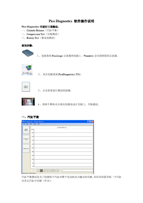
Pico Diagnostics 软件操作说明Pico Diagnostics可进行三项测试:一、Cylinder Balance(汽缸平衡)二、Compression Test(压缩测试)三、Battery Test(蓄电池测试)使用步骤:1、连接您的PicoScope示波器到电脑上。
Wondows会识别到您的示波器。
2,双击电脑桌面PicoDiagnostics图标。
3,点击您要进行测试的按键。
4,将两个鳄鱼夹分别夹到蓄电池正负极上,开始测试。
一、汽缸平衡汽缸平衡测试是为了检测每个汽缸对整个发动机动力输出的贡献。
有好多因素导致一个汽缸比其它汽缸少贡献(作功)。
这包括(但不限于以下三点):•低压缩•喷油嘴故障•火花塞故障轻微的不平衡并不一定是发动机有故障。
在暖机过程中,多数发动机运转都会有一定的轻微不平衡。
积炭和发动机磨损也会对发动机性能有影响。
进行汽车平衡测试步骤启动Pico Diagnostics软件,点击左边“Cylinder Balance”按钮加载程序。
按照下面提示连接示波器并进行测试:•连接示波器•起动发动机•运行测试A) 连接示波器用USB线连接示波器到您电脑上的USB接口。
将TA000线缆一头连在示波器A通道上,另一头接红、黑两个鳄鱼夹子,分别夹在蓄电池正负极上,如上图所示。
B) 起动发动机C) 运行测试点击窗口左下角的按钮开始测试。
一个新的进程指示器会出现在屏幕上,如下图:在进程指示器显示100%前,不要关闭发动机。
数据已被分析,如果测试成功,结果会以条形柱显示,如下图:D) 结果结果总是显示最好的汽缸为100%。
如果测试不能产生结果,请确认:•与蓄电池的连接良好•发电机皮带松紧程度适当如果你打开头灯并且打开其它电路负载,如后档风玻璃加热器和雾灯,也会对检测结果有帮助。
对有些发动机是很难产生结果的,这包括:•发动机缸数大于8•一些有双质量飞轮的发动机•有惯量阻尼器的发动机•有氙气灯的汽车如果仍有问题,如果你检查了上述提及的几点,软件仍无法产生结果,请将失败的检测数据保存下来,发送到sales@.E) 汽缸平衡控制你可以在柱形图上右击鼠标得到控制菜单,如:Variation(差异)以叠加蓝色条柱显示每缸贡献(作功)的差异。
潍柴动力赛门铁克防病毒软手册

赛门铁克防病毒软件客户端安装手册潍柴动力扬州柴油机有限责任公司二〇一四年三月目录1卸载所有其他杀毒软件 (2)2 赛门铁克防病毒软件安装程序选择 (3)3 判断电脑内存大小 (4)4 低配置电脑杀毒软件安装步骤 (7)5 中、高配置电脑杀毒软件安装步骤 (12)1卸载所有其他杀毒软件因为2种杀毒软件不能并存(否则会导致死机、蓝屏的故障),因此安装赛门铁克防病毒软件之前必须先卸载其它杀毒软件,如360杀毒、360安全卫士、金山毒霸、金山卫士、MCAFEE、瑞星等。
通过在“开始---程序--控制面板—添加或删除程序”将其它杀毒软件卸载。
2赛门铁克防病毒软件安装程序选择赛门铁克防病毒软件可以根据电脑配置及安全控制需求制定不同的策略,低配置的电脑仅安装基本的防护功能,确保电脑使用性能不受影响,中、高配置的电脑则安装所有防护功能,提供最高防护安全,每台客户端都可以通过服务器端得到及时防护更新。
低配置的电脑:内存1G及以下电脑或设备编号为589-846以前的电脑(如设备编号为589-845)。
中、高配置的电脑:内存1G以上电脑或设备编号为589-846及以后的电脑(如设备编号为589-847)。
3判断电脑内存大小右键点“我的电脑”,选择“属性”出现以下界面则表示该电脑内存为512M,应该安装低配的赛门铁克杀毒软件。
出现以下界面则表示该电脑为2.00GB的内存,即该电脑内存为2G,应该安装装标配的赛门铁克杀毒软件。
4低配置电脑杀毒软件安装步骤点“开始”——“运行”输入\\10.30.37.106, 点“确定”打开“cdr”文件夹,找到“symantec”文件夹打开“symantec”文件夹双击“赛门铁克低配安装程序--低配电脑(内存等于及小于1G).exe”点“运行”,程序正在安装程序安装完成,点“取消”,重启电脑重启电脑后需等待杀毒软件更新病毒库(自动更新,约30分钟),更新完成后在屏幕右下角出现以下界面双击,出现以下界面,表示杀毒软件安装成功。
Eaton EFGVS软件:Eaton消防站点监控和图形可视化软件许可安装指南说明书

DISCLAIMER OF WARRANTIES AND LIMITATIONOF LIABILITYThe information, recommendations, descriptions and safety notations in this document are based on Eaton Corporation’s (“Eaton”) experience and judgment and may not cover all contingencies. If further information is required, an Eaton sales office should be consulted. Sale of the product shown in this literature is subjectto the terms and conditions outlined in appropriate Eaton selling policies or other contractual agreement between Eaton and the purchaser.THERE ARE NO UNDERSTANDINGS, AGREEMENTS, WARRANTIES, EXPRESSED OR IMPLIED, INCLUDING WARRANTIES OF FITNESS FOR A PARTICULAR PURPOSE OR MERCHANTABILITY, OTHER THAN THOSE SPECIFICALL Y SET OUT IN ANY EXISTING CONTRACT BETWEEN THE PARTIES. ANY SUCH CONTRACT STATES THE ENTIRE OBLIGATION OF EATON. THE CONTENTS OF THIS DOCUMENT SHALL NOT BECOME PART OF OR MODIFY ANY CONTRACT BETWEEN THE PARTIES.In no event will Eaton be responsible to the purchaser or user in contract, in tort (including negligence), strict liability or other-wise for any special, indirect, incidental or consequential damage or loss whatsoever, including but not limited to damage or loss of use of equipment, plant or power system, cost of capital, loss of power, additional expenses in the use of existing power facilities, or claims against the purchaser or user by its customers resulting from the use of the information, recommendations and descriptions contained here in. The information contained in this manual is subject to change without notice.EFGVS License installation guide Contents1. INITIAL KEY INSTALLATION (4)1.1 Obtain your Authentication Key (4)1.2 Contact Eaton (4)1.3 Installing your License Key (5)2. CHECKING YOUR EXISTING LICENSE (6)3. UPDATING YOUR LICENSE (7)Material code DescriptionEF-SITEMONITOR Monitoring software license without graphical visualisation maps including an EC0232interfaceEFGVS1-2Graphical visualisation software license 1-2 panels including an EC0232 interface EFGVS3-6Graphical visualisation software license up to 6 panels including an EC0232 interface EFGVS7-10Graphical visualisation software license up to 10 panels including an EC0232 interface EFGVS11-PLUS Graphical visualisation software license above 10 panels including an EC0232 interface EFGVS7-10-TCPIP Graphical visualisation software license up to 10 panels with TCP/IP InterlinkEFGVS11-PLUS-TCPIP Graphical visualization software license above 10 panels with TCP/IP Interlink EFGVS-DESIGN Graphical visualisation designer software license - no panel connectivityEFGVS-PREMIUMDESGN Graphical visualisation premium designer software license including an EC0232 interfaceEFGVS License installation guide1. Initial key installation1.1. Obtain your authentication keyAfter downloading the software from the Eaton website (/ fire-community), when you first run the Designer, Viewer or Site Monitor software variant, you will be prompted for a license key. The popup window will resemblethe following:Send to EatonAn important element here is the Authentication Key, which is an alpha-numeric sequence required by the Eaton employee to produce your eventual license key. This key is linked to a given computer and is automatically generated bythe computer.Before you contact Eaton, please ensure you have this key available, either written down on paper or displayed on your computer screen nearby. It should be noted that, every time you load the software, this key will change. This is normal and any of the Authentication Keys produced will still be acceptable by Eaton, providing they come from the same computer, were produced recently and that you pass other verification.1.2. Contact EatonThe next step is to contact Eaton to get a Site Reference and a License Key provided for the computer on which the software is installed. We suggest you send an email message to MVDO-Fire-T******************** with your license key request, including the Authentication Key mentioned in section 2.In order to accelerate the process, you should also provide the following information:•Y our company name and customer ID reference (on the order acknowledgment)•Y our company address •The order reference•The order date (format YYYY -MM-DD)•The order code(s) for the license(s) you have purchased with the quantity for each reference if several.•Site/Project nameIf your request is urgent, you can place a phone call to +44 (0)1302 303350.otee:N Note: If you have any question related to this section please contact your local Eaton representative who can liaise with our central technical support team. They will insure that your software license key is generated rapidly.1.3. Installing your license keyOnce you have received your actual License Key and Site Reference, you should enter them as shown below:Please ensure you enter the site reference and license key precisely in the same format you were provided. We recommend these are copied and pasted (from the email message) into the software if possible. Remember, it is OK if the Authentication Key is different from the one you sent to Eaton.When done, please click on Register and Continue . The software will now load and can be used.Received back from EatonClick when theKey is acceptedEFGVS License installation guide2. Checking your existing licenseIf you want to check the status of your existing license, you can do this by selecting the About option in the Help drop down menu. This is available in all three applications (Designer, Viewer and Site Monitor) and in the same location. On this screen, you will see your current license key along with other details about your license. Any time you contact Eaton regarding your current license, you will be asked for your license key. If you need to send your license key by email, you can selectthe key with your mouse like normal text and then copy and paste it into an email.EFGVS License installation guide3. Updating your LicenseIf your license expires, you will be automatically prompted for a new license key. However, if you request a new license key, or are issued with a new license, you can change your existing license key by selecting the Update License option in the Help drop down menu. This is available in all three applications (Designer, Viewer and Site Monitor) and in the same location. Similar to the method of installing your first license key, you will be provided a Site Reference and License Key by Eaton. Generally, you will need to provide Eaton with your current license key, soplease refer to the previous section on how to achieve this.Send to Eaton if requiredReceived back from EatonClick when theKey is acceptedEFGVS License installation guideEatonEMEA Headquarters Route de la Longeraie 7 1110 Morges, Switzerland Eaton.eu© 2017 EatonAll Rights ReservedPrinted in UKPublication No. IB152003EN/CSSC-302 Pub Reference: PR214-212-500-01 May 2017Eaton is a registered trademark. All trademarks are propertyof their respective owners.。
系统操作手册-客户端系统

医疗器械不良事件监测系统CDR1.0-06操作手册客户端系统分册国家食品药品监督管理局药品评价中心国家药品不良反应监测中心二〇一二年五月目录1前言 (4)2用户计算机要求 (4)2.1计算机硬件要求: (4)2.2用户计算机软件要求 (4)3安装 (8)4登录方式 (17)5医疗器械不良事件报告表操作 (21)5.1录入医疗器械不良事件报告表 (21)5.1.1进入方式 (21)5.1.2操作方法及步骤 (22)5.2医疗器械不良事件报告表浏览查询 (35)5.2.1进入方式 (35)5.3医疗器械不良事件报告表查看 (36)5.3.1进入方式 (36)5.3.2操作方法及步骤 (36)5.4医疗器械不良事件报告表修改 (37)5.4.1进入方式 (37)5.4.2操作方法及步骤 (37)5.5医疗器械不良事件报告表导出 (38)5.5.1进入方式 (38)5.5.2操作方法及步骤 (38)5.6医疗器械不良事件报告表导出 (39)5.6.1进入方式 (39)5.6.2操作方法及步骤 (39)5.7医疗器械不良事件报告表全部导出 (41)5.7.1进入方式 (41)5.7.2操作方法及步骤 (42)5.8医疗器械不良事件报告表导入 (42)5.8.1进入方式 (42)5.8.2操作方法及步骤 (42)5.9医疗器械不良事件数据上传操作 (44)5.9.1进入方式 (44)5.9.2操作方法及步骤 (44)6系统功能操作 (48)6.1基础数据更新 (48)6.1.1进入方式 (48)6.1.2操作方法及步骤 (48)6.2数据库备份 (49)6.2.1进入方式 (49)6.2.2操作方法及步骤 (50)6.3数据库恢复 (51)6.3.1进入方式 (51)6.3.2操作方法及步骤 (51)6.4分发用户 (52)6.4.1进入方式 (52)6.4.2操作方法及步骤 (53)7卸载 (54)7.1卸载应用程序 (54)器械离线客户端及操作手册下载地址:http://114.255.93.220/CDR/help/index/index.ht ml1 前言医疗器械不良事件监测系统客户端主要实现基层用户通过客户端软件录入医疗器械不良事件报告、导入导出不良事件报告及基础数据下载等功能。
北京东方迪格保险综合业务实训教学软件操作手册解读

保险实训软件操作手册目录系统简介 .。
..。
.。
..。
..。
..。
..。
..。
.。
.....。
.....。
..。
...。
.。
.。
.。
.。
...。
.。
.....。
.。
.。
..。
..。
.。
.。
.。
.。
.。
.。
...。
3功能特点 .。
..。
.。
..。
..。
.。
.。
.。
.。
.。
..。
.。
..。
..。
..。
.。
.。
.。
.。
.。
...。
.。
.。
...。
.。
.。
.。
..。
...。
.。
.....。
.。
... 3业务流程 .。
.。
..。
.。
.。
....。
.。
...。
..。
....。
.。
......。
......。
.。
...。
..。
...。
....。
.。
.。
..。
...。
.。
.。
..。
.。
..。
.。
.。
.。
.. 4系统操作指南 .。
...。
.。
..。
.。
...。
.。
....。
.。
.。
.。
..。
..。
.。
.。
.。
.。
......。
.。
.。
.。
....。
..。
....。
.。
.。
.。
.... 5第一节系统界面说明。
..。
...。
....。
.。
.。
..。
.。
.。
.。
.。
...。
.。
..。
..。
.。
.。
.。
...。
.。
.。
...。
.。
.。
.。
..。
.。
...。
5λ界面组成 .....。
.。
.。
.。
.。
...。
.。
.。
.。
.。
..。
..........。
.。
..。
..。
.。
.....。
..。
.。
...。
.。
.。
..。
.. 5第二节系统登陆说明 ....。
.。
...。
.。
.。
.。
..。
..。
.。
....。
.。
.。
.。
.。
...。
...。
.。
.。
........。
..。
..。
......。
...。
.。
.。
..。
..。
.。
6λ如何登陆系统 .......。
.....。
.。
.....。
..。
..。
....。
..........。
..。
.。
...。
.。
....。
.。
...。
...。
...。
.。
6第三节财产险操作指南 . .。
.....。
.....。
.。
..。
...。
....。
.。
.。
..。
.。
.。
..。
..。
.。
.。
..。
..。
..。
电控天然气故障诊断仪使用说明书(ECI)_V1.0
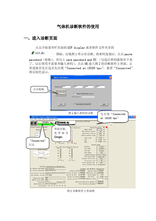
气体机诊断软件的使用一、进入诊断页面点击开始菜单栏里面的GCP display 或者软件文件夹里的图标,出现图1所示对话框,将密码复制后,点击pastepassword(粘贴),再勾上save password and SN (勾选后密码就保存下来了,以后使用不需要再输入密码),点击OK 进入图2的诊断软件主界面,正常连接首先右边会先出现“Connected at 19200 bps”,接着“Connected”将以绿色显示。
图1输入密码对话框图2诊断软件主界面图界面名称,此界面为Gauges二、故障码界面介绍进入故障码管理页面的方法,单击主界面菜单栏上的“Page” ,在下拉菜单上单击“Faults”,会弹出图3所示的故障码显示界面。
Page菜单图3 故障码显示界面从故障码区可以看到当前和历史故障,双击历史/故障的红点后出现如图4所示的故障码信息界面。
图4 故障码信息界面在故障码信息界面当点击View Fault Snapshot 按钮后出现故障快照数据界面,显示内容为当故障触发时的数据采样,如图5所示。
图5快照数据界面三、监测及保存发动机数据用鼠标右键点击所需要采集的参数,这个参数的方框随即会显示为高亮,点击该按钮跳出故障码数据对话框,显示所发生故障时的一些参数,如,时间,转速等。
如图6所示。
选中该参数后方框显示为高亮图6 选择监测变量也可以通过导入已选好参数的模板来进行参数选择。
操作如图7。
点击菜单栏上的Plot/Log——选择Load RecorderSettings——在出现对话框中选择模板——点击Load按钮图7 导入模板对话框导入完成后,模板已选好的参数将高亮显示,如图8所示。
图8 导入模板后参数选择完成界面通过右键逐个选择或者导入模板的方法进行参数选择后,按下键盘P键或Ctrl+P,出现采集数据界面,如图9 所示。
图9 采集数据界面测试完毕后,对采集数据的保存方法如图10、图11所示。
ELUA诊断软件的使用说明

ห้องสมุดไป่ตู้
诊断软件的使用
• 出现的画面
点击这个按 钮会出现右 边画面
以上画面可以看到控制器,驱动器,电机的详细参数(PLC configuration)
END
出现这个画面是正在连接(电脑软件和控制器正在连接)
诊断软件的使用
• 出现的画面
正在连接控制器,并且读取伺服系统的参数
诊断软件的使用
• 出现的画面
点击这个按 钮
可以保存 结果 打开已有 的诊断结 果
诊断软件的使用
• 出现的画面
这边是各个菜单栏,点击后会出现对应的 参数栏
点击show data后显示的控制器的部分参数,左边是各个查看的参数
Solar Huawei I-V曲线诊断系统用户手册说明书
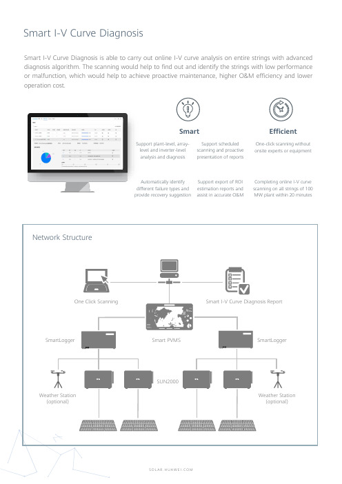
Smart I-V Curve Diagnosis is able to carry out online I-V curve analysis on entire strings with advanced diagnosis algorithm.The scanning would help to find out and identify the strings with low performance or malfunction,which would help to achieve proactive maintenance,higher O&M efficiency and lower operation cost.Network StructureSmartLogger Smart PVMS Smart I-V Curve Diagnosis ReportOne Click ScanningSUN2000 Weather Station(optional)SmartLoggerWeather Station(optional) SmartSupport plant-level, array-level and inverter-level analysis and diagnosisSupport scheduled scanning and proactive presentation of reportsAutomatically identify different failure types and provide recovery suggestion Support export of ROIestimation reports andassist in accurate O&MEfficientOne-click scanning withoutonsite experts or equipmentCompleting online I-V curvescanning on all strings of 100MW plant within 20 minutesTechnical SpecificationsSmart String Inverter SUN2000-215KTL-H0, SUN2000-215KTL-H3, SUN2000-185KTL-H1 …Data Logger SmartLogger2000,SmartLogger3000Management System Smart PVMS Scanning Time<1s per stringSampling Points per I-V Curve 128Voltage Accuracy 0.5%rdg. + 1dgt. (rdg.>5, dgt.= 0.3)Current Accuracy0.5%rdg. + 2dgt. (rdg.>0.3, dgt.= 0.006)Smart I-V Curve Diagnosis Verified by TUVString-level Management Smart I-V Curve DiagnosisReal time monitoring Fault Analysis01234567890100200300400500600700800900100011001200130014001500Normal Curve Current Mismatch Curve (Shade)01234567890100200300400500600700800900100011001200130014001500Normal Curve PV String Voltage Abnormal (Diode short circuit)String I-V Curve ComparisonC u r r e n t [A ]Voltage [V]C u r r e n t [A ]Voltage [V]●System level closed-loop control to keep the systemoperating in the state of maximum irradiation and optimal power output of PV module●Automatic tracking angle optimization and control byusing AI technology, automatic sensing of shading andweather information. No need for additional sensingequipment, free from manual and empirical dependenceSmart PVMSSUN2000Weather Station(optional)SmartLogger Weather Station(optional)Network Structure SmartLogger……Tracker Control Unit (TCU)……Network Control Unit (NCU)SUN2000……Tracker Control Unit (TCU)……Smart Tracker Control Algorithm(SDS)is a valuable software of AI technology based and closed-loop control.By using the SDS,together with Smart PVMS,SmartLogger and SUN2000inverters,the trackers’angle can be automatically controlled and optimally adjusted to achieve higher yields.The yields can be increased by~1%especially in complex terrain and weather scenarios,and it will bring higher revenue to the customer.Technical SpecificationsSmart String Inverter SUN2000-215KTL-H0, SUN2000-215KTL-H3, SUN2000-185KTL-H1 …Data Logger SmartLogger2000,SmartLogger3000 seriesManagement System Smart PVMSTracking Angle Accuracy0.5°Smart Tracker Control Algorithm Verified by TUVCloudy and rainy daysTracking the angle of the sun is not the best way to get maximum irradiation when without consideration that direct sunlight becomesdiffuse reflection in this scenario.Trackers are flattened at a small angle to receive more diffuselight, so as to get maximum irradiation.Traditional tracker algorithm Smart Tracker Control AlgorithmReverse-tracking stage in the morning and at duskShadows in the front and back rows of modules,withoutconsideration of complex terrainThe SDS algorithm allows trackers to find the optimal angle foreach, effectively avoiding shadow occlusions.Traditional tracker algorithm Smart Tracker Control AlgorithmComparison of Tracker Algorithms and Angles。
VP泵系统诊断软件使用说明书-20140305
VP 泵系统诊断软件使用说明书
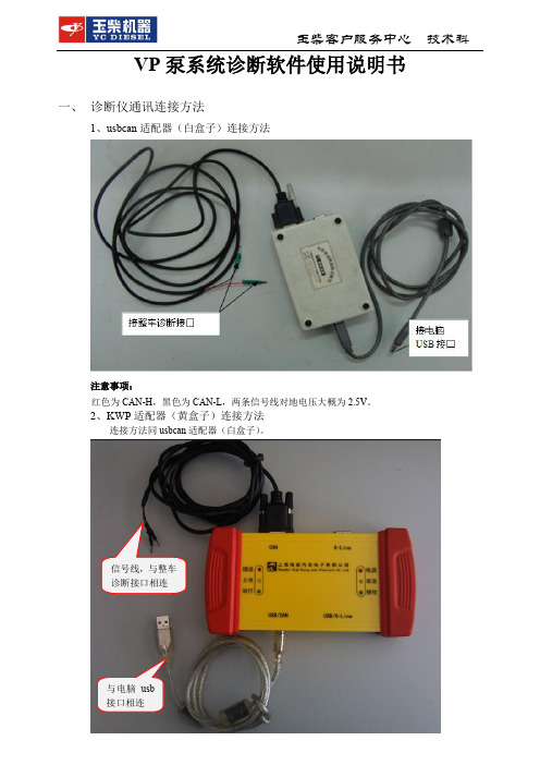
一、 诊断仪通讯连接方法
1、usbcan 适配器(白盒子)连接方法
注意事项:
红色为CAN-H ,黑色为CAN-L ,两条信号线对地电压大概为2.5V 。
2、KWP 适配器(黄盒子)连接方法
连接方法同usbcan 适配器(白盒子)。
与电脑usb 接口相连
信号线,与整车
诊断接口相连
二、 运行诊断软件
1、 集成式诊断软件(升级平台版)运行方法:
点击电脑桌面左下角的“开始”---程序---电控发动机故障诊断仪,打开应用程序,进入下图所示界面
三、 诊断软件功能使用说明
故障诊断区
状态监测区
命令按钮区。
- 1、下载文档前请自行甄别文档内容的完整性,平台不提供额外的编辑、内容补充、找答案等附加服务。
- 2、"仅部分预览"的文档,不可在线预览部分如存在完整性等问题,可反馈申请退款(可完整预览的文档不适用该条件!)。
- 3、如文档侵犯您的权益,请联系客服反馈,我们会尽快为您处理(人工客服工作时间:9:00-18:30)。
5 点击 Finish
步骤三:检查 ECOM 驱动安装完成后,诊断线 POWER 灯是否由红色变为绿色,详见图片如下:
ECOM 驱动安装前,诊断线 POWER 灯为红色
ECOM 驱动安装完成,诊断线 POWER 灯为绿色
三、 诊断软件登录界面
点击电脑左下角“开始—所有程序—文件夹 4G Display—
2. ###.cal 程序的刷写。正常连接好诊断仪并起动诊断软件。 点击菜单栏 file 选项,在下拉菜单中点击 Load Calibration from disk,弹出 Select File to Load 对话框
在上面“Select File to Load”对话框,查找到需要刷写的###.cal 程序,点 击 Load 即可进行刷写,同时显示 “Cal Load/Save Progress”对话框,同时 显示刷写进度条。
当刷写进度条到达 100%后表示刷写完毕,点击“Done”按钮完成###.cal 程序刷写。(刷写程序后不需手动关电保存)。 ii. 数据采集 1. 数据参数的选择(默认选择最多 20 个参数)。数据参数选择后,系统自动 记录数据,此时记录键由灰色变为绿色。使用鼠标右键对参数的选取或取 消。
玉柴客户服务中心 技术科
若打开诊断软件时出现如下图提示,原因为 ECOM 驱动未安装或安装失败,请参考 ECOM 驱动安 装步骤安装驱动。
四、 诊断软件使用说明
a) 诊断界面说明 i. 主界面:在诊断界面的左上角有操作菜单栏,具体含义见图上标注。
page 菜单,主 要用于诊断 界面的选取
Comm port 菜单, 主要用于 com 口 或 CAN 的设置
玉柴客户服务中心 技术科
连接诊断线到电脑 usb 接 口,出现该图片点击取消, 进行步骤二。若未弹出此向 导,直接进行步骤二。
步骤二:双击或解压
,进入文件夹 ,双击进入驱动安装界面:
,找到安装程序
1 点击 Next
2 点击 Next
3 点击 Next
4 点击 Install
玉柴客户服务中心 技术科
Port/Log 菜单,主要 用于绘图以及在采集 数据时作标记记录
file 菜单,主要 用于刷写程序
进气歧管压力
电瓶电压 程序版本号
冷却 水温
进气 温度
油门 位置
节气门
故障灯 发动机转速
运行状态 燃料类型 燃料控制模式
ii. 故障码界面
转速
冷却水温 进气温度 点火提前角
闭环修正与 自适应值
节气门目标值 和实际值
玉柴客户服务中心 技术科
断缸测试 命令按钮。
2. 节气门检测 a) 在做节气门检测之前,需要选取相应的参数,并按“ctrl+P”调出 MAP 图,建议采集参数:转速、节气门命令值和反馈值、油门命令值和反 馈值等;
b) 在诊断仪软件“Page”下拉菜单选取“Faults”或“Tests”界面。点击 节气门测试“DBW test”按钮,选择 Enabled 进入测试模式,然后分 别缓慢和快速地踩下、松开油门踏板,同时注意观察节气门与油门之 间的跟随性,如跟随性一致,表示节气门正常。
记录好 的标记。
玉柴客户服务中心 技术科
iii. 故障码的读取与保存 在诊断仪菜单,在 Page 下拉菜单选择 Faults,如图。该界面同时显示当前 故障码和历史故障码。在发动机故障的原因未找到并解决之前,请务必不 要清楚历史故障码。
1. 故障码的保存。保存故障码有两种方式:a)、把故障码界面截屏保存;b)、 以 fss 格式对对单一故障码进行保存。 a) 选择 Faults 故障码界面,按下电脑键盘的截屏键“Prnt Scm”或“Fn+ Prnt Scm”进行屏幕截屏,然后把截屏粘贴到 DOC 文档保存即可;
b) 逐个双击历史故障码,在 Historic Fault Information 对话框点击“View Snap Shot Data”按钮,弹出“Snap Shot Data”对话框,点击“Save” 按钮,在“Fault Snapshot Filename”对话框的文件名栏输入对应的故 障名称,最后点击保存即可完成故障码的保存。其余故障码依次方法 保存。
电瓶电压
历史故障码
怠速开关状态
油门目标值 和实际值
怠速开关电压
当前故障码
断缸测试按钮
节气门பைடு நூலகம்试按钮
点火线圈 充电时间
iii. HDService 界面
玉柴客户服务中心 技术科
转速 进气歧管压力 节气门前压力 冷却水温
进气温度 点火提前角 燃料温度
氧浓度命令 实际氧浓度
iv. Service2 界面
保存路径默认为诊断仪的安装 目录下。保存路径可自己选择。
4. 记录标记。在数据记录过程中,对发现异常状况应及时做好标记以方便后 续的数据分析。方法:同时按下电脑上 ctrl+m 键或依次点击诊断仪菜单 Plot/log→New Mark,弹出 New Mark 对话框,在 Mark Comment 录入简要 说明后点击 Ok 即可,根据需要,可记录多个标记。(标记完的数据保存方 法参考第三步数据参数的保存)
环境压力 环境湿度 环境温度
WGP 目标 WGP 实际值
TIP 目标值 氧传感器状态
历史故障码清除按钮
自适应清〇按钮
v. Tests 界面
断缸检测
玉柴客户服务中心 技术科
节气门 检测
b) 诊断仪的连接 i. 需要的设备 1. 安装有 4G_display 软件的电脑 2. Ecom 专用诊断连接设备 ii. CFV 系统诊断通讯是采用 CAN 方式通讯的。在诊断界面的 Comm port 选项里 勾选 Ecom,并按照下图对话框设置 configure Ecom…
玉柴客户服务中心 技术科
ECI-CFV 诊断软件安装使用说明书
一、 CFV 诊断软件的安装
解压
,进入文件夹
,双击安装程序后进入步骤如下:
,找到安装程序
点击 Next
点击 Next
点击 Next
等待
点击 finish
点击 No 不重启电脑
二、 安装 ECOM 驱动
步骤一:连接 ECOM 诊断线到电脑 usb 接口
2. MAP 图形。通过 MAP 图可以直观监控发动机运行的实际工况,更好地发 现和处理问题。同时按下电脑上的 Ctrl+P 键或依次点击诊断软件左上角菜 单 Plot/log→Plot Tags,可调出 MAP 图。
3. 数据参数的保存。点击在 MAP 图上左上角菜单 File→Save,弹出 Save Plot 对话框,在 Filename 处输入文件名,然后点击 save 按钮即可保存数据(保 存路径默认为诊断仪的安装目录下)。
图标”,弹出登录界面如下:
第一步:将登录密码(G0FF-SECW-RJMR-AUUW)复制。 (或手动录入密码到 Password 对话框后,直接跳到第三步)。
第二步:点击 Paste Password 按钮
第四步:点击 OK 按钮
第三步:在 Save password and S/N 前打勾
玉柴客户服务中心 技术科
iii. 连接方式如图。
玉柴客户服务中心 技术科
诊断仪连接方式 为 CAN 通讯连接
当诊断软件连接成功后,Ecom 上的 CAN 灯和 USB 灯会以绿灯点亮并连续闪烁, PC 诊断软件同时绿色显示 connected 标识
CAN 和 USB 灯
诊断仪连接 成功标识
c) 诊断仪的使用 i. 程序的刷写。程序刷写分为两种类型,即后缀名分别为.mot 和.cal 的程序。 1. xxx.mot 程序的刷写。正常连接好诊断仪并起动诊断软件。 点击菜单栏 file 选项,在下拉菜单中点击“Reprogram Target”,弹出 Select S-record/Mot File 对话框
在上面“Select S-record/Mot File”对话框,查找到需要刷写的.mot 程序, 点击 Load 即可进行刷写,同时显示刷写进度条对话框,
玉柴客户服务中心 技术科
刷写完毕后自动弹出“Success”对话框,点击“Ok”按钮完成 xxx.mot 程 序刷写。(刷写程序后不需手动关电保存)。
建议文件名与 故障码一致。
2. 故障码的清除 a) 故障码清除只能清除历史故障码,当前故障码是不可清除的。 b) 选择 Faults 故障码界面,双击需要清除的历史故障码,在 Historic Fault Information 对话框点击 clear All Faults 按钮,再点击“Yes”,即可清除 全部历史故障码。建议:在清除历史故障码前,先保存历史故障码!
节气门测 试按钮。
缓慢踩下、松 开油门测试
快速踩下、松 开油门测试
c) 检测完毕后,点击节气门测试“DBW test”按钮,选择 off 或关闭点火 开关退出测试模式。
玉柴客户服务中心 技术科
iv. 自适应清零 1. 在打开诊断仪软件,点击左上角菜单“Page”,选取 Service1 界面,点击“Clear Adaptive”按钮,即可把 EEPROM 储存的修正值同时归零。
自适应清〇按钮
v. 电控零部件的测试 1. 断缸检测 a) 在做断缸检测之前,需要选取相应的参数,并按“ctrl+P”调出 MAP 图,建议采集参数:转速、进气歧管压力、点火提前角、节气门位置、 油门位置、断缸命令、氧浓度、闭环修正、自适应等;
b) 在诊断仪软件“Page”下拉菜单选取“Faults”或“Tests”界面。点击 断缸命令“spark kill”按钮,在下拉菜单分别点击“coil1、coil2„„ coil6”,即可分别切断第一缸、第二缸„„第六缸的点火。断缸检测完 成后及时保存数据。 建议操作方法:依次点击 coil1→Normal→coil2→Normal„„coil6→ Normal,每一次点击间隔时间 3 秒以上。