电动扳手力矩对应表
最新扭力对照表

螺栓公称直径mm
螺栓强度 屈服强度
级
N/mm²
22
24
27
30
33
36
39
拧紧力矩N.m
4.6 5.6 6.8 8.8 10.9 12.9
240 300 480 640 900 1080
230~290 330~377 450~530 540~680 670~880 900~1100 928~1237
18
20
120~150 170~210
5.6
300
5~7 12~15 25~32 45~55 70~90 110~140 150~190 210~270
6.8
480
7~9 17~23 33~45 58~78 93~124 145~193 199~264 282~376
8.8
640 9~12 22~30 45~59 78~104 124~165 193~257 264~354 376~502
235
M12
28.5
加上半身力
螺丝扭力标准
施力操作要领 加全身力
压上全身重量 压上全身重量
螺栓强度 屈服强度
级
N/mm²
4.6
240
未注明拧紧力矩要求时,参考下表(普通螺栓拧紧力矩)
螺栓公称直径mm
6
8
10
12
14
16
拧紧力矩N.m
4~5 10~12 20~25 36~45 55~70 90~110
螺栓拧紧力矩标准
表单编 号:技
螺纹公称 直径尺寸
d/mm
施加在扳 手上的拧 紧力矩
M/N.m
M6
3.5
M6-M24螺钉或螺母的拧紧力矩(操作者参考)
力矩表

力矩对照表(仅适用凯德克T8扳手头,拉伸部分仅适用ITH的版手头)
位置 第一段下法兰 第二段下法兰 第三段下法兰 第四段下法兰 塔筒与机舱 叶片与轮毂 轮毂与低速轴 第一次力矩60% 4301NM 260bar 2678NM 163bar 2678NM 163bar 1427NM 90bar 1000NM 电动扳手 1000NM 电动扳手 534KN 拉伸 784bar 第二次力矩80% 5734NM 347bar 3571NM 218bar 3571NM 218bar 1903NM 118bar 448KN 拉伸 903bar 280KN 拉伸 564bar 712KN 拉伸 1045bar 第三次力矩100% 7168NM 430bar 4464NM 271bar 4464NM 271bar 2379NM 147bar 560KN 拉伸 1129bar 350KN 拉伸 705bar 890KN 拉伸 1306bar
力矩对照表(仅适用凯德克T5扳法兰 第三段下法兰 第四段下法兰 塔筒与机舱 叶片与轮毂 轮毂与低速轴 第一次力矩60% 4301NM 395bar 2678NM 246bar 2678NM 246bar 1427NM 131bar 1000NM 电动扳手 1000NM 电动扳手 534KN 拉伸 784bar 第二次力矩80% 5734NM 527bar 3571NM 328bar 3571NM 328bar 1903NM 175bar 448KN 拉伸 903bar 280KN 拉伸 564bar 712KN 拉伸 1045bar 第三次力矩100% 7168NM 659bar 4464NM 410bar 4464NM 410bar 2379NM 219bar 560KN 拉伸 1129bar 350KN 拉伸 705bar 890KN 拉伸 1306bar
凯特克HYTORC液压扳手力矩对照表

材质
一般构造用钢
机械制造用钢
鉻钼合金钢
镍鉻钼合金钢
螺栓
螺母
扭矩值
扭矩值
扭矩值
扭矩值
KGM
NM
KGM
NM
KGM
NM
KGM
NM
M
22mm
137
23
225
M16
24mm
10
98
14
53
M18
27mm
14
84
49
480
M2
30mm
41
402
69
676
M22
32mm
23
225
34
333
55
539
凯特克HYTORC液压扳手力矩对照表
———————————————————————————————— 作者:
———————————————————————————————— 日期:
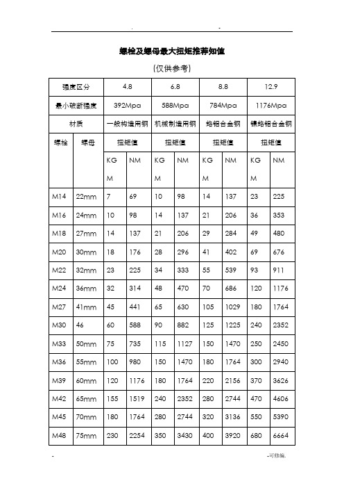
螺栓及螺母最大扭矩推荐知值
(仅供参考)
强度区分
4.8
6.8
8.8
12.9
最小破断强度
392Mpa
588Mpa
784Mpa
553
8
1
0
2037
3
75
4662
593
5750
2182
32
6
8597
8318
1
00
2328
34
8
5276
672
7850
2473
36
9
5583
71
54
1296
127
38
4
50
2746
凯特克HYTORC液压扳手力矩对照表

20090
M110
155mm
1670
16366
2550
24990
M120
175mm
2030
19894
3050
29890
1、以上是德国工业标准,表中扭矩值为螺栓达到屈服极限的70%时所测定.
2、建议锁紧力矩为:表中数据X(70-80)%.
例如:M48,8.8级螺栓,则锁紧力矩为:400X80%=320(Kg-m)
XLT系列压力/扭力对照表
油泵压力
设定值
扳手输出扭力值
HY-1XLT(A)
HY-3XLT(A)
HY-5XLT(A)
HY-8XLT(A)
PSI
Bar
ftib
kgm
Nm
ftib
kgm
Nm
ftib
kgm
Nm
ftib
kgm
Nm
1000
69
130
18
177
320
44
435
560
78
761
800
111
1087
1200
1919
2454
340
3335
3520
488
4784
4600
317
634
88
862
1478
205
2009
2566
356
3488
3680
510
5002
4800
331
662
92
900
1544
214
2098
2678
371
3640
3840
532
5219
凯特克HYTORC液压扳手力矩对照表

120
1176
M27
41mm
45
441
65
630
105
1029
180
1764
M30
46
60
588
90
882
125
1225
240
2352
M33
50mm
75
735
115
1127
150
1470
250
2450
M36
55mm
100
980
150
1470
180
1764
300
2940
M39
60mm
120
1176
1600
2400
166
2752
381
3740
4740
657
6442
6264
868
8514
12600
1746
2600
179
2978
413
4047
5135
711
6979
6776
939
9209
13650
1891
2800
193
3204
444
4355
5530
766
7516
7288
1010
9905
14700
2037
PSI
Bar
ftib
kgm
Nm
ftib
kgm
Nm
ftib
kgm
Nm
ftib
kgm
Nm
1000
69
1210
168
1645
电动扭力扳手扭矩的选择与调整 扭力扳手技术指标

电动扭力扳手扭矩的选择与调整扭力扳手技术指标SGDD系列电动扭力扳手是装配螺纹件及螺栓的机械化施工工具,具有自动掌控扭矩功能。
电动扭力扳手广泛应用于栓焊结构桥梁的架设,厂房、塔架及化工、冶金、发电设备的安装。
大型机械、起重设备和车辆装配作业,以及对螺纹紧固件的扭矩及轴向拉力有严格要求的场合。
电动扭力扳手由主机和掌控仪两部分构成,主机接受双重绝缘单相串激式电动机和减速机构,结构新奇、体积小、重量轻、安全牢靠。
由于接受静扭结构,运转平稳,无振动、无冲击,噪音小,操不受反力矩的影响,因而劳动强度低。
额定电压220V50/60Hz精度5%。
电动扭力扳手扭矩的选择与调整1、用户可在50—3500N.m的范围内任意选择相应规格的电动扭力扳手。
2、掌控仪面板上有扭矩调解旋钮。
刻有0—10个刻度值。
细调旋钮的作用是在粗调两档之间进行调整补偿,以提高扭矩掌控精度。
(见后页)3、调整方法:产品出厂时带有扭矩测试数据卡片,供用户标定时参考,用户可依据所需扭矩选择某一刻度值,按拧紧螺栓的操作方法,拧紧螺栓,用测力扳手或其它测力仪器测出螺栓的实际扭矩值,若扭矩相差较小,可用细调加以补偿,若相差较大,可将粗调向上或向下调一档,反复几次即可获得所需扭矩值。
您可能还对这些产品感喜好:大量程预置扭力扳手扭矩扳手检定仪可调式电动扭力扳手安装用的预置式扳手圆螺母专用数显扭矩扳手拆卸螺栓增力扳手电子扭矩扳手高精度数显式测力计脚手架螺丝扳手动态扭矩检测仪扭力扳手校准仪按钮拉力测试机扭簧表测力计电批检验仪手持式数显推拉力仪动态扭矩测试仪数显扭矩扳手微型压力测力仪可连电脑的数显扭力扳手扭矩放大器电动扭力扳手螺栓拆装工具数显扭力扳手如何使用与维护数显扭力扳手的使用方法和维护信任还是有很多用户不是很清楚吧,所以对数显扭力扳手使用方法和维护还不太娴熟的用户,赶快跟着我一起学习一下吧。
数显扭力扳手使用方法:1、旋下手把后端的电池盖,正极朝前装入2节5号电池,然后旋紧电池盖;2、短按“O/C”键,开启电源,液晶显示器字符全显,扳手开始自检,3 秒后置零;3、单位选择,按“▼”选择所需的测量单位;4、测量方式选择:按“M”键,选择“跟踪F”或“峰值H”模式;5、扭矩值报警预置:按“M”至“预置P”模式,再按“P”键确定所需预置扭矩值的位数,按“▲”及“▼”键确定所需预置报警数值,预置结束后按“M”键退出预置模式,回到“跟踪F”状态,或再按一次“M”键进入“峰值H”状态。
液压扭力扳手附件及扭矩对照表

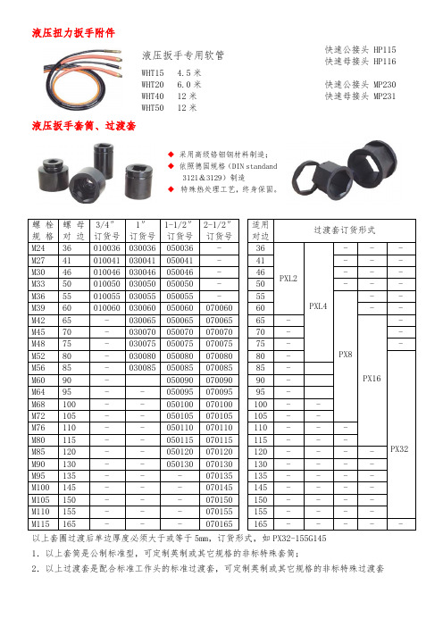
液压扭力扳手附件液压扳手专用软管WHT15 4.5米 WHT20 6.0米 WHT40 12米 WHT50 12米快速公接头 HP115 快速母接头 HP116快速公接头 MP230 快速母接头 MP231液压扳手套筒、过渡套◆ 采用高级铬钼钢材料制造; ◆ 依照德国规格(DIN standand3121&3129)制造◆ 特殊热处理工艺,终身保固。
螺 栓 规 格 螺 母 对 边 3/4″ 订货号 1″ 订货号 1-1/2″ 订货号 2-1/2″ 订货号 适用对边 过渡套订货形式M24 36 010036 030036 050036 - 36 PXL2PXL4 - - -M27 41 010041 030041 050041 - 41 - - - M30 46 010046 030046 050046 - 46 - - -M33 50 010050 030050 050050 - 50 - - - M36 55 010055 030055 050055 - 55 PX8 - - M39 60 010060 030060 050060 070060 60 - -M42 65 - 030065 050065 070065 65 - PX16 - M45 70 - 030070 050070 070070 70 - - M48 75 - 030075 050075 070075 75 - - M52 80 - 030080 050080 070080 80 -PX32 M56 85 - 030085050085 070085 85 -M60 90 - 050090 070090 90 -M64 95 - - 050095 070095 95 -M68 100 - - 050100 070100 100 - -M72 105 - - 050105 070105 105 - -M76 110 - - 050110 070110 110 - - -M80 115 - - 050115 070115 115 - - -M85 120 - - 050120 070120 120 - - - - M90 130 - - 050130 070130 130 - - - - M95 135 - - - 070135 135 - - - - M100 145 - - - 070145 145 - - - - M105 150 - - - 070150 150 - - - - M110 155 - - - 070155 155 - - - - M115165 - - - 070165 165 - - - - -以上套圈过渡后单边厚度必须大于或等于5mm ,订货形式,如PX32-155G145 1.以上套筒是公制标准型,可定制英制或其它规格的非标特殊套筒;2.以上过渡套是配合标准工作头的标准过渡套,可定制英制或其它规格的非标特殊过渡套螺栓、螺母扭矩推荐表1.以上扭矩数值是德国工业标准,是该螺栓达到屈服扭矩值的70%所测定;2.推荐锁紧力矩值为表中数据乘以80%为宜,以设备安装中的扭矩要求为准;3.如果是高温高压的容器要进行计算,或用表中的扭矩值100%锁紧。
凯特克力矩扳手TC-HY-3MXT对照表

PRESSURE INPRESSURE INPSI FT. LBS.KGM NM BAR 150048066651104160051271694110180057680781124200064089868138220070497954152240076810610411652600832115112817928008961241215193300096013313012073200102414213882203400108815014752343600115215915622483800121616816482624000128017717352764200134618618252904400141219519143034600147820420043174800154421420933315000161022321833455200167423222693585400173824023563725600180224924433865800186625825304006000193026726164146200199427627034276400205828527904416600212229328774556800218630229634687000225031130504827200231632031404967400238232932295107600244833933195247800251434834085388000258035734975528200264636635875658400271237536765798600277838437665938800284439338556079000291040239456209200297441140326349400303842041186489600310242942056629800316643842926761000032304474379690* ISO DOCUMENT 9000REV.01/1998TORQUE INHYTORCTOOL MODEL: HY-3MXTPRESSURE/TORQUE CONVERSION CHARTStandard Torque ChartIMPORTANT SAFETY INSTRUCTIONSWARNING: Your HYTORC TORQUE MACHINE is a power tool, and as with any power tool, certain safety precautions should be observed to avoid accidents or personal injury. The following tips will assist you.•READ ALL INSTUCTIONS.•KEEP WORK AREA CLEAN AND WELL LIT.•CONSIDER WORK AREA ENVIRONMENT. Electrical Pumps should never be used in an atmosphere which can be considered potentially volatile. If there is any doubt, use an air pump. Also Note: metal to metal contact can cause sparks, precautions should be taken.•AVOID PREMATURE TOOL STARTING. The Pump Remote Control is for the TOOL OPERATOR only.•STAY CLEAR DURING OPERATION. In most cases, the tool will allow “hands free” operation. If the tool must be held or steadied during operation, use alternative means of securing the tool to the application•GUARD AGAINS ELECTRIC SHOCK. Ensure the pump is properly grounded and the proper voltage is being used.•STORE IDLE TOOLS. When not in use, tool sand accessories should be properly stored to avoid deterioration•USE RIGHT TOOL. Don’t force small tools or attachments to do the job of a larger tool. Don’t use a tool for purposes not intended.•PROPER SAFETY ATTIRE. When handling/operating hydraulic equipment use work gloves, hard hats, safety shoes and other applicable clothing.•USE SAFETY GLASSES.•MOVING EQUIPMENT. Do not use hydraulic hoses, uni-swivels, pump power or remote cords as means of moving the equipment.•MAINTAIN TOOLS WITH CARE. For top performance, inspect tools, powerpack and accessories for visual damage frequently and always prior to use. Always follow instruction for proper tool and pump maintenance. Refer to the Operations Maintenance Section for further clarification•STAY ALERT. Watch what you are doing. Use Common sense. Do not use power equipment under the influence of any mood altering substances.•PRIOR TO OPERATIONEnsure that all hydraulic connections are securely connected and there is no leakageVerify that the Hydraulic hoses are not kinked or otherwise damaged.Ensure the square drive and its retainer are fully and securely engaged.Be certain that all connectors, elbows, fitting and swivels are not bent, loose or damaged.•PRIOR TO USE.Check sockets for size, quality and flaws. (Do not use if questionable)Cycle tool to ensure proper function.Locate a solid, secure reaction point.Be sure the reaction arm retaining clamp is fully engaged.Be sure the hydraulic hoses are free of the reaction point.Pressurize the system momentarily; if the tool tends to “ride up” or to “creep”, stop and re-adjust the reaction arm to a more solid and secure position.NOTE: Remain clear of the reaction arm during operation and never put body parts between reaction arm and reaction surfaces.•ALWAYS USE QUALITY ACCESSORIES. Always use top quality impact sockets in good condition which are the correct size and fully engage the nut. Hidden flaws, however, remain a possibility which could cause breakage, so stay clear of sockets during operation•DO NOR USE other equipment to enhance performance (Hammer on Socket/Tool)NOTE: Hytorc Pumps are designed to operate Hytorc Tools only. Damage may occur to the pump or the product that is being operated due to misuse.SAVE THESE INSTRUCTIONS FOR FUTURE USE!。
扳手力矩表说明书

Clamping and manual forces in clamping levers with eccentrical camForce details, calculationELESA and GANTER models all rights reserved in accordance with the law.Always mention the source when reproducing our drawings.2022C l a m p i n g l e v e r s The eccentric principle has two advantages: A large clamping force Fs and a self-locking mechanism as soon as the dead centre is exceeded.All theoretical attempts to describe the ratio between manual and clamping force will ultimately rest only on assumptions in some parameters. The actually prevailing conditions are influenced by a number of different factors.The values given in the tables below are therefore based on practical specifications and findings and rest on test series which have shown which clamping forces can be achieved by applying the specified manual forces.The maximum permitted pretensioning force of each thread size will not be exceeded by operating the lever.3General informationClamping and manual forcesCalculationTo account for the above theoretical and arithmetical alternative for determining clamping and manual forces, a potential solution will be shown below which will ultimately also prove the plausibility of the values given in the table using a calculation example.When theoretically determining the clamping force Fs resulting from the manual force, two points must be observed in particular:First, there are the geometrical conditions existing at the eccentric which call for an arithmetically complex approach if one wishes to take account of the exact conditions. Secondly, the friction occurring at several points will have a strong impact on the achievable clamping force.1st alternative, eccentricLooking at the developed view arising in an eccentric through the rolling motion, one will find that this is caused by a sinusoidal curve.The result is that the gradient angle w above the swivel range changes permanently, causing an extension of the selflocking range and of the force transmission.However, the arithmetical description of this approach is highly complex.10/2022ELESA and GANTER models all rights reserved in accordance with the law.Always mention the source when reproducing our drawings.2023C l a m p i n g l e v e r s Clamping and manual forces in clamping levers with eccentrical camForce details, calculation3Substitute calculation modelIn simple terms and assuming a constant gradient, the existing sine curve may be seen as a wedge which will result in a sufficiently accurate and approximate substitute calculation model which is a great deal less complex.A friction value will be assumed for the axis of rotation and the circumference of the eccentric, which will in reality be strongly influenced by external factors and may therefore diverge accordingly.2nd alternative, eccentricA 90° motion of the manual lever covers the stroke h.Equations and model calculations Safety noticesThe design of applications involving clamping levers with eccentrical cam should always be made including an adequate safety factor. Usual safety actors for static loads 1,2 to 1,5; pulsating 1,8 to 2,4 and alternating 3 to 4. To be increased proportionally in applications with higher safety requirements.Disclaimer:The information and recommendations we give are made without commitment and excluding any liability, unless we have committed ourselves expressly and in writing to give such information and recommendations. All products are standard parts designed for a variety of different uses and have as such been subjected to extensive standard tests; users should determine in their own test series, for which we will not be liable, whether a product will be suitable for certain special applications and uses.10/2022。
