PLC英文翻译
自动化常用英文缩写

自动化常用英文缩写自动化(Automation)是指利用计算机、机器人和其他自动化设备来代替人力完成工作的过程。
在自动化领域中,人们往往使用缩写词来简化和快速传达信息。
以下是一些自动化常用英文缩写及其解释:1. PLC - Programmable Logic Controller(可编程逻辑控制器)PLC是一种用于控制和监控自动化系统的计算机控制器。
它可以接收输入信号,进行逻辑运算,然后输出控制信号,从而实现自动化控制。
2. SCADA - Supervisory Control and Data Acquisition(监控与数据采集)SCADA系统用于监控和控制工业过程中的设备和参数。
它可以实时采集数据并显示在操作员界面上,同时还能进行报警和记录。
3. HMI - Human Machine Interface(人机界面)HMI是一种用于人机交互的设备,通常是触摸屏或者显示屏。
它通过图形化界面向操作员展示自动化系统的状态,并提供操作和控制功能。
4. DCS - Distributed Control System(分布式控制系统)DCS是一种用于控制和监控大型工业过程的系统。
它由多个分布式控制器组成,可以实现分布式控制和集中管理。
5. MES - Manufacturing Execution System(创造执行系统)MES是一种用于管理和控制创造过程的系统。
它可以跟踪生产进度、采集生产数据,并提供实时的生产监控和报告。
6. CNC - Computer Numerical Control(计算机数控)CNC是一种用于控制机械设备的技术。
它通过计算机程序控制设备的运动和操作,实现高精度和自动化加工。
7. RFID - Radio Frequency Identification(射频识别)RFID是一种用于识别和跟踪物体的技术。
它使用无线电信号来读取和写入存储在RFID标签中的信息,实现自动化的物流管理和库存控制。
PLC组成及工作原理

PLC组成及工作原理PLC是Programmable Logic Controller的简称,中文翻译为可编程逻辑控制器。
它是一种用于自动控制工业过程的数字计算机系统。
PLC由硬件和软件两部分组成,下面将详细介绍PLC的组成和工作原理。
1.硬件组成:PLC的硬件主要包括中央处理器(CPU)、输入输出模块(I/O模块)、电源模块、通信模块以及其他辅助硬件。
-中央处理器(CPU)是PLC的核心,负责接收输入信号、执行程序指令并控制输出信号。
CPU通常具有高性能的微处理器,能够进行复杂的计算和逻辑判断。
-输入输出模块(I/O模块)负责与外部世界进行数据交换。
输入模块用于接收现场传感器、开关等设备的信号,输出模块用于控制执行机构、显示设备等。
-电源模块提供稳定的电源供电,确保PLC正常运行。
-通信模块可实现PLC与其他设备(如人机界面、计算机、远程监控系统等)之间的数据传输和通信。
-其他辅助硬件包括存储器、时钟模块、编程口等,用于存储程序、记录运行时间、与外部进行编程等功能。
2.软件组成:PLC的软件主要包括操作系统、开发环境和用户程序。
-操作系统是PLC的核心软件,用于管理硬件资源、执行程序指令、实现通信等功能。
- 开发环境提供PLC程序的开发、调试和维护工具。
常见的开发环境有LD(Ladder Diagram,梯形图)、FBD(Function Block Diagram,功能块图)、ST(Structured Text,结构化文本)等多种编程语言。
-用户程序是PLC的应用程序,由工程师根据控制需求编写。
用户程序根据输入信号的状态和逻辑关系,通过中央处理器进行逻辑判断并控制输出信号,实现自动化控制。
3.工作原理:PLC的工作原理主要分为输入端、处理端和输出端。
-输入端:PLC通过输入模块接收来自现场的输入信号,如开关状态、传感器信号等。
输入信号会被转换成数字信号,并传给中央处理器。
中央处理器会周期性地扫描输入信号,并将其存储在内部存储器中,以供后续的程序处理。
可编程控制器外文翻译、中英文翻译、外文文献翻译
毕业设计中英文翻译院系专业班级姓名学号指导教师20**年 4 月Programmable Logic Controllers (PLC)1、MotivationProgrammable Logic Controllers (PLC), a computing device invented by Richard E. Morley in 1968, have been widely used in industry including manufacturing systems, transportation systems, chemical process facilities, and many others. At that time, the PLC replaced the hardwired logic with soft-wired logic or so-called relay ladder logic (RLL), a programming language visually resembling the hardwired logic, and reduced thereby the configuration time from 6 months down to 6 days [Moody and Morley, 1999].Although PC based control has started to come into place, PLC based control will remain the technique to which the majority of industrial applications will adhere due to its higher performance, lower price, and superior reliability in harsh environments. Moreover, according to a study on the PLC market of Frost and Sullivan [1995], an increase of the annual sales volume to 15 million PLCs per year with the hardware value of more than 8 billion US dollars has been predicted, though the prices of computing hardware is steadily dropping. The inventor of the PLC, Richard E Morley, fairly considers the PLC market as a 5-billion industry at the present time.Though PLCs are widely used in industrial practice, the programming of PLC based control systems is still very much relying on trial-and-error. Alike software engineering, PLC software design is facing the software dilemma or crisis in a similar way. Morley himself emphasized this aspect most forcefully by indicating [Moody and Morley, 1999, p. 110]:`If houses were built like software projects, a single woodpecker could destroy civilization.”Particularly, practical problems in PLC programming are to eliminate software bugs and to reduce the maintenance costs of old ladder logic programs. Though the hardware costs of PLCs are dropping continuously, reducing the scan time of the ladder logic is still an issue in industry so that low-cost PLCs can be used.In general, the productivity in generating PLC is far behind compared to other domains, for instance, VLSI design, where efficient computer aided design tools are in practice. Existent software engineering methodologies are not necessarily applicable to the PLC basedsoftware design because PLC-programming requires a simultaneous consideration of hardware and software. The software design becomes, thereby, more and more the major cost driver. In many industrial design projects, more than SO0/a of the manpower allocated for the control system design and installation is scheduled for testing and debugging PLC programs [Rockwell, 1999].In addition, current PLC based control systems are not properly designed to support the growing demand for flexibility and reconfigurability of manufacturing systems. A further problem, impelling the need for a systematic design methodology, is the increasing software complexity in large-scale projects.PLCs (programmable logic controllers) are the control hubs for a wide variety of automated systems and processes. They contain multiple inputs and outputs that use transistors and other circuitry to simulate switches and relays to control equipment. They are programmable via software interfaced via standard computer interfaces and proprietary languages and network options.Programmable logic controllers I/O channel specifications include total number of points, number of inputs and outputs, ability to expand, and maximum number of channels. Number of points is the sum of the inputs and the outputs. PLCs may be specified by any possible combination of these values. Expandable units may be stacked or linked together to increase total control capacity. Maximum number of channels refers to the maximum total number of input and output channels in an expanded system. PLC system specifications to consider include scan time, number of instructions, data memory, and program memory. Scan time is the time required by the PLC to check the states of its inputs and outputs. Instructions are standard operations (such as math functions) available to PLC software. Data memory is the capacity for data storage. Program memory is the capacity for control software.Available inputs for programmable logic controllers include DC, AC, analog, thermocouple, RTD, frequency or pulse, transistor, and interrupt inputs. Outputs for PLCs include DC, AC, relay, analog, frequency or pulse, transistor, and triac. Programming options for PLCs include front panel, hand held, and computer.Programmable logic controllers use a variety of software programming languages for control. These include IEC 61131-3, sequential function chart (SFC), function block diagram (FBD), ladder diagram (LD), structured text (ST), instruction list (IL), relay ladder logic (RLL), flow chart, C, and Basic. The IEC 61131-3 programming environment provides support for five languages specified by the global standard: Sequential Function Chart,Function Block Diagram, Ladder Diagram, Structured Text, and Instruction List. This allows for multi-vendor compatibility and multi-language programming. SFC is a graphical language that provides coordination of program sequences, supporting alternative sequence selections and parallel sequences. FBD uses a broad function library to build complex procedures in a graphical format. Standard math and logic functions may be coordinated with customizable communication and interface functions. LD is a graphic language for discrete control and interlocking logic. It is completely compatible with FBD for discrete function control. ST is a text language used for complex mathematical procedures and calculations less well suited to graphical languages. IL is a low-level language similar to assembly code. It is used in relatively simple logic instructions. Relay Ladder Logic (RLL), or ladder diagrams, is the primary programming language for programmable logic controllers (PLCs). Ladder logic programming is a graphical representation of the program designed to look like relay logic. Flow Chart is a graphical language that describes sequential operations in a controller sequence or application. It is used to build modular, reusable function libraries. C is a high level programming language suited to handle the most complex computation, sequential, and data logging tasks. It is typically developed and debugged on a PC. BASIC is a high level language used to handle mathematical, sequential, data capturing and interface functions.Programmable logic controllers can also be specified with a number of computer interface options, network specifications and features. PLC power options, mounting options and environmental operating conditions are all also important to consider.2、ResumeA PLC (programmable Logic Controller) is a device that was invented to replace the necessary sequential relay circuits for control.The PLC works by looking at its input and depending upon their state, turning on/off its outputs. The user enters a program, usually via software or programmer, which gives the desired results.PLC is used in many "real world" applications. If there is industry present, chance are good that there is a PLC present. If you are involved in machining, packing, material handling, automated assembly or countless other industries, you are probably already using them. If you are not, you are wasting money and time. Almost any application that needs some type of electrical control has a need for a PLC.For example, let's assume that when a switch turns on we want to turn a solenoid on for 5second and then turn it off regardless of how long the switch is on for. We can do this with a simple external timer. But what if the process included 10 switches and solenoids? We should need 10 external times. What if the process also needed to count how many times the switch individually turned on? We need a lot of external counters.As you can see the bigger the process the more of a need we have for a PLC. We can simply program the PLC to count its input and turn the solenoids on for the specified time.We will take a look at what is considered to be the "top 20" PLC instructions. It can be safely estimated that with a firm understanding of these instructions one can solve more than 80% of the applications in existence.Of course we will learn more than just these instruction to help you solve almost ALL potential PLC applications.The PLC mainly consists of a CPU, memory areas, and appropriate circuits to receive input/output data. We can actually consider the PLC to be a box full of hundreds or thousands of separate relay, counters, times and data storage locations,Do these counters,timers, etc. really exist? No,they don't "physically" exist but rather they simulated and be considered software counters, timers, etc. . These internal relays are simulated through bit locations in registers.What does each part do? Let me tell you.Input RelaysThese are connected to the outside world.They physically exsit and receive signals from switches,sensors,ect..Typically they are not relays but rather they are transistors.Internal Utility RelaysThese do not receive signals from the outside world nor do they physically exist.they are simulated relays and are what enables a PLC to eliminate external relays.There are also some special relays that are dedicated to performing only one task.Some are always on while some are always off.Some are on only once during power-on and are typically used for initializing data that was stored.CountersThese again do not physically exist. They are simulated counters and they can be programmed to count pulses.Typically these counters can count up,down or both up anddown.Since they are simulated,they are limited in their counting speed.Some manufacturers also include high-speed counters that are hardware based.We think of these as physically existing.Most times these counters can count up,down or up and down.TimersThese also do not physically exist.They come in many varieties and increments.The most common type is an on-delay type.Others include off-delays and both retentive and non-retentive types.Increments vary from 1ms through 1s.Output RelaysThere are connected to the outside world.They physically exist and send on/off signals to solenoids,lights,etc..They can be transistors,relays,or triacs depending upon the model chosen Data StorageTypically there are registers assigned to simply store data.They are usually used as temporary storage for math or data manipulation.They can also typically be used to store data when power is removed form the PLC.Upon power-up they will still have the same contents as before power was moved.Very convenient and necessary!A PLC works by continually scanning a program.We can think of this scan cycle as consisting of 3 important steps.There are typically more than 3 but we can focus on the important parts and not worry about the others,Typically the others are checking the system and updating the current internal counter and timer values,Step 1 is to check input status,First the PLC takes a look at each input to determine if it is on off.In other words,is the sensor connected to the first input on?How about the third...It records this data into its memory to be used during the next step.Step 2 is to execute program.Next the PLC executes your program one instruction at a time.Maybe your program said that if the first input was on then it should turn on the first output.Since it already knows which inputs are on/off from the previous step,it will be able to decide whether the first output should be turned on based on the state of the first input.It will store the execution results for use later during the next step.Step 3 is to update output status.Finally the PLC updates the status the outputs.It updates the outputs based on which inputs were on during the first step and the results executing your program during the second step.Based on the example in step 2 it would now turn on the firstoutput because the first input was on and your program said to turn on the first output when this condition is true.After the third step the PLC goes back to step one repeats the steps continuously.One scan time is defined as the time it takes to execute the 3 steps continuously.One scan time is defined as the time it takes to execute the 3 steps listed above.Thus a practical system is controlled to perform specified operations as desired.3、PLC StatusThe lack of keyboard, and other input-output devices is very noticeable on a PLC. On the front of the PLC there are normally limited status lights. Common lights indicate;power on - this will be on whenever the PLC has powerprogram running - this will often indicate if a program is running, or if no program is runningfault - this will indicate when the PLC has experienced a major hardware or software problemThese lights are normally used for debugging. Limited buttons will also be provided for PLC hardware. The most common will be a run/program switch that will be switched to program when maintenance is being conducted, and back to run when in production. This switch normally requires a key to keep unauthorized personnel from altering the PLC program or stopping execution. A PLC will almost never have an on-off switch or reset button on the front. This needs to be designed into the remainder of the system.The status of the PLC can be detected by ladder logic also. It is common for programs to check to see if they are being executed for the first time, as shown in Figure 1. The ’first scan’ input will be true on the very first time the ladder logic is scanned, but false on every other scan. In this case the address for ’first scan’ in a PLC-5 is ’S2:1/14’. With the logic in the example the first scan will seal on ’light’, until ’clear’ is turned on. So the light will turn on after the PLC has been turned on, but it will turn off and stay off after ’clear’ is turned on. The ’first scan’ bit is also referred to at the ’first pass’ bit.Figure 1 An program that checks for the first scan of the PLC4、Memory TypesThere are a few basic types of computer memory that are in use today.RAM (Random Access Memory) - this memory is fast, but it will lose its contents when power is lost, this is known as volatile memory. Every PLC uses this memory for the central CPU when running the PLC.ROM (Read Only Memory) - this memory is permanent and cannot be erased. It is often used for storing the operating system for the PLC.EPROM (Erasable Programmable Read Only Memory) - this is memory that can be programmed to behave like ROM, but it can be erased with ultraviolet light and reprogrammed.EEPROM (Electronically Erasable Programmable Read Only Memory) – This memory can store programs like ROM. It can be programmed and erased using a voltage, so it is becoming more popular than EPROMs.All PLCs use RAM for the CPU and ROM to store the basic operating system for the PLC. When the power is on the contents of the RAM will be kept, but the issue is what happens when power to the memory is lost. Originally PLC vendors used RAM with a battery so that the memory contents would not be lost if the power was lost. This method is still in use, but is losing favor. EPROMs have also been a popular choice for programming PLCs. The EPROM is programmed out of the PLC, and then placed in the PLC. When the PLC is turned on the ladder logic program on the EPROM is loaded into the PLC and run. This method can be very reliable, but the erasing and programming technique can be time consuming. EEPROM memories are a permanent part of the PLC, and programs can be stored in them like EPROM. Memory costs continue to drop, and newer types (such as flash memory) are becoming available, and these changes will continue to impact PLCs.5、Objective and Significance of the ThesisThe objective of this thesis is to develop a systematic software design methodology for PLC operated automation systems. The design methodology involves high-level description based on state transition models that treat automation control systems as discrete event systems, a stepwise design process, and set of design rules providing guidance and measurements to achieve a successful design. The tangible outcome of this research is to find a way to reduce the uncertainty in managing the control software development process, that is, reducing programming and debugging time and their variation, increasing flexibility of theautomation systems, and enabling software reusability through modularity. The goal is to overcome shortcomings of current programming strategies that are based on the experience of the individual software developer.A systematic approach to designing PLC software can overcome deficiencies in the traditional way of programming manufacturing control systems, and can have wide ramifications in several industrial applications. Automation control systems are modeled by formal languages or, equivalently, by state machines. Formal representations provide a high-level description of the behavior of the system to be controlled. State machines can be analytically evaluated as to whether or not they meet the desired goals. Secondly, a state machine description provides a structured representation to convey the logical requirements and constraints such as detailed safety rules. Thirdly, well-defined control systems design outcomes are conducive to automatic code generation- An ability to produce control software executable on commercial distinct logic controllers can reduce programming lead-time and labor cost. In particular, the thesis is relevant with respect to the following aspect Customer-Driven ManufacturingIn modern manufacturing, systems are characterized by product and process innovation, become customer-driven and thus have to respond quickly to changing system requirements.A major challenge is therefore to provide enabling technologies that can economically reconfigure automation control systems in response to changing needs and new opportunities. Design and operational knowledge can be reused in real-time, therefore, giving a significant competitive edge in industrial practice.Higher Degree of Design Automation and Software QualityStudies have shown that programming methodologies in automation systems have not been able to match rapid increase in use of computing resources. For instance, the programming of PLCs still relies on a conventional programming style with ladder logic diagrams. As a result, the delays and resources in programming are a major stumbling stone for the progress of manufacturing industry. Testing and debugging may consume over 50% of the manpower allocated for the PLC program design. Standards [IEC 60848, 1999; IEC-61131-3, 1993; IEC 61499, 1998; ISO 15745-1, 1999] have been formed to fix and disseminate state-of-the-art design methods, but they normally cannot participate in advancingthe knowledge of efficient program and system design.A systematic approach will increase the level of design automation through reusing existing software components, and will provide methods to make large-scale system design manageable. Likewise, it will improve software quality and reliability and will be relevant to systems high security standards, especially those having hazardous impact on the environment such as airport control, and public railroads.System ComplexityThe software industry is regarded as a performance destructor and complexity generator. Steadily shrinking hardware prices spoils the need for software performance in terms of code optimization and efficiency. The result is that massive and less efficient software code on one hand outpaces the gains in hardware performance on the other hand. Secondly, software proliferates into complexity of unmanageable dimensions; software redesign and maintenance-essential in modern automation systems-becomes nearly impossible. Particularly, PLC programs have evolved from a couple lines of code 25 years ago to thousands of lines of code with a similar number of 1/O points. Increased safety, for instance new policies on fire protection, and the flexibility of modern automation systems add complexity to the program design process. Consequently, the life-cycle cost of software is a permanently growing fraction of the total cost. 80-90% of these costs are going into software maintenance, debugging, adaptation and expansion to meet changing needs [Simmons et al., 1998].Design Theory DevelopmentToday, the primary focus of most design research is based on mechanical or electrical products. One of the by-products of this proposed research is to enhance our fundamental understanding of design theory and methodology by extending it to the field of engineering systems design. A system design theory for large-scale and complex system is not yet fully developed. Particularly, the question of how to simplify a complicated or complex design task has not been tackled in a scientific way. Furthermore, building a bridge between design theory and the latest epistemological outcomes of formal representations in computer sciences and operations research, such as discrete event system modeling, can advance future development in engineering design.Application in Logical Hardware DesignFrom a logical perspective, PLC software design is similar to the hardware design of integrated circuits. Modern VLSI designs are extremely complex with several million parts and a product development time of 3 years [Whitney, 1996]. The design process is normally separated into a component design and a system design stage. At component design stage, single functions are designed and verified. At system design stage, components are aggregated and the whole system behavior and functionality is tested through simulation. In general, a complete verification is impossible. Hence, a systematic approach as exemplified for the PLC program design may impact the logical hardware design.可编程控制器1、前言可编程序的逻辑控制器(PLC),是由Richard E.Morley 于1968年发明的,如今已经被广泛的应用于生产、运输、化学等工业中。
可编程控制器本科毕业论文中英文翻译材料关于PLC外文翻译
可编程控制器本科毕业论文中英文翻译材料关于PLC外文翻译中文翻译可编程控制器技术可编程序控制器(Programmable Logic Controller,习惯上简称为PLC)是以微处理器为核心的通用工业自动化装置。
是20世纪60年代末在继电器控制系统的基础上开发出来的,它将传统的继电器控制技术与计算机技术和通信技术融为一体,具有结构简单、性能优越、可靠性高、灵活通用、易于编程、使用方便等优点。
具体来说,PLC的特点表现为以下几个方面:?硬件的可靠性高。
PLC专业在工业环境的恶劣条件下应用而设计。
一个设计良好的PLC能置于有很强电噪声、电磁干扰、机械振动、极端温度和湿度很大的环境中。
在硬件设计方面,首先是选用优质器件,再就是采用合理的系统结构,加固、简化安装,使它易于抗振冲击,对印刷电路板的设计、加工和焊接都采取了极为严格的工艺措施,而在电路、结构及工艺上采取了一些独特的方式。
由于PLC 本身具有很高的可靠性,所以在发生故障的部位大多集中在输入/输出的部位以及如传感器件、限位开关、光电开关、电磁阀、电机等外围装置上。
?编程简单,使用方便。
用微机实现自动控制,常使用汇编语言编程,难于掌握,要求使用者具有一定水平的计算机硬件和软件知识。
PLC采用面向控制过程、面向问题的编程方式,与目前微机控制常用的汇编语言相比,虽然在PLC内部增加了解释程序,增加了程序的执行时间,但对大多数的机电控制设备来说,这种损耗是微不足道的。
?接线简单,通用性好。
在电信号匹配的情况下,PLC的接线只需将输入信号的设备(按钮、开关等)与PLC输入端子连接,将接受输出信号执行控制任务的执行元件(接触器、电磁阀)与PLC输出端子连接。
接线简单、工作量少,省去了传统的继电器控制系统的接线和拆线的麻烦。
PLC的编程逻辑提供了能随要求而改变的逻辑关系,这样生产线的自动化过程就能随意改变。
这种性能使PLC具有很高的经济效益。
用于连接现场设备的硬件接口实际上已经设计成为PLC的组成部分,模块化的自诊断接口电路能指出故障,并易于排除故障与替换故障部件,这样的软硬件设计就使现场电气人员与技术人员易于使用。
基础知识PLC
什么是PLC,可编程序控制器的定义可编程序控制器,英文称Programmable Controller,简称PC。
但由于PC容易和个人计算机(Personal Computer)混淆,故人们仍习惯地用PLC作为可编程序控制器的缩写。
它是一个以微处理器为核心的数字运算操作的电子系统装置,专为在工业现场应用而设计,它采用可编程序的存储器,用以在其内部存储执行逻辑运算、顺序控制、定时/计数和算术运算等操作指令,并通过数字式或模拟式的输入、输出接口,控制各种类型的机械或生产过程。
PLC是微机技术与传统的继电接触控制技术相结合的产物,它克服了继电接触控制系统中的机械触点的接线复杂、可靠性低、功耗高、通用性和灵活性差的缺点,充分利用了微处理器的优点,又照顾到现场电气操作维修人员的技能与习惯,特别是PLC的程序编制,不需要专门的计算机编程语言知识,而是采用了一套以继电器梯形图为基础的简单指令形式,使用户程序编制形象、直观、方便易学;调试与查错也都很方便。
用户在购到所需的PLC后,只需按说明书的提示,做少量的接线和简易的用户程序编制工作,就可灵活方便地将PLC应用于生产实践。
可编程序控制器一直在发展中,所以至今尚未对其下最后的定义。
国际电工学会(IEC)曾先后于1982.11;1985.1和1987.2发布了可编程序控制器标准草案的第一,二,三稿。
在第三稿中,对PLC作了如下定义:可编程序控制器是一种数字运算操作电子系统,专为在工业环境下应用而设计。
它采用了可编程序的存储器,用来在其内部存储执行逻辑运算、顺序控制、定时、计数和算术运算等操作的指令,并通过数字的,模拟的输入和输出,控制各种类型的机械或生产过程。
可编程序控制器及其有关的外围设备,都应按易于与工业控制系统形成一个整体、易于扩充其功能的原则设计。
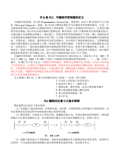
定义强调了PLC是:1 数字运算操作的电子系统——也是一种计算机2 专为在工业环境下应用而设计3 面向用户指令——编程方便4 逻辑运算、顺序控制、定时计算和算术操作5 数字量或模拟量输入输出控制6 易与控制系统联成一体7 易于扩充PLC编程应注意七大基本原则PLC编程应注意以下基本原则。
PLC-外文文献+翻译

Programmable logic controllerA programmable logic controller (PLC) or programmable controller is a digital computer used for automation of electromechanical processes, such as control of machinery on factory assembly lines, amusement rides, or lighting fixtures。
PLCs are used in many industries and machines。
Unlike general—purpose computers,the PLC is designed for multiple inputs and output arrangements, extended temperature ranges, immunity to electrical noise,and resistance to vibration and impact。
Programs to control machine operation are typically stored in battery—backed or non—volatile memory. A PLC is an example of a real time system since output results must be produced in response to input conditions within a bounded time,otherwise unintended operation will result。
1.HistoryThe PLC was invented in response to the needs of the American automotive manufacturing industry。
plc的定义概念

plc的定义概念
PLC(Programmable Logic Controller),翻译过来就是可编程逻辑
控制器,它是一种采用可编程指令的数字化操作控制器。
PLC主要用于工业控制系统中,它可以对生产流程进行自动化控制。
它通过读取传感器信号,计算输出控制信号来控制生产流程和设备运行。
PLC有着广泛的应用,在制造业、汽车、食品加工、化学工业等领域都得到了广泛使用。
PLC的主要功能包括数据采集、数据处理、快速运算、应变能力强等。
PLC的工作原理是当输入模块读取到传感器信号后,将信号转化为数字信号,然后再通过中央处理器进行处理,最后再输出给输出模块产生
控制信号,以控制电路的开关状态。
PLC有着高可靠性、高稳定性和可编程性等优点。
PLC还具有较好的兼
容性和可扩充性,可以随着需求的变化进行相应的修改和升级。
PLC的编程方式通常有图形化编程和文字化编程两种方式。
大多数PLC
厂商提供了可视化的编程工具和相应的编程语言环境。
总的来说,PLC是一种运算能力强、稳定性高、可编程的数字化控制器。
它有着广泛的应用,并且具有较好的兼容性和可扩充性,能够随着需
求的变化进行相应的修改和升级。
弄清国外公司后缀名,那些BV、S.A. de C.V.、Mfg、GmbH、Sdn
S.P.A.,是意大利语societa per azioni之缩略称谓,指(共同)股份公司,
AB,是瑞典语Altiebolag的缩写,中文为公司的意思。
公司名称中包括AG的主要是德国和瑞士,如:
PSI BT BUSINESS TECHNOLOGY FOR INDUSTRIES AG(德国)
XCHINDLER INFORMATIK A.G(瑞士)
S.A.则主要出现在法国、瑞士、比利时、卢森堡、意大利、西班牙、葡萄牙、巴拿马、阿根延、墨西哥和智利。如:
CO.,LT,是company limited的缩写,翻译为“有限责任公司”
Inc,是incorporation的缩写,意思是“团体、法人组织、公司”
Corp.,是corporation的缩写,意思是“团体、法人组织、公司”
BV,是荷兰文Besloten Vennootshap met beperkte aansprak-elijkhed的缩写,指私人有限公司
弄清国外公司后缀名,那些BV、S.A. de C.V.、Mfg、GmbH、Sdn
今天搜集信息的时候有家公司后面有个B.V. 不知道意思,上网查了下,顿时醒悟,
以下是比较全的一篇文章内容,全copy了 ,想与大家分享下
CO,是company的缩写,意思是“公司”。
LTD,是limited的缩写,意思是“有限的”,常单独出现在公司名称,指有限责任公司
NV,是荷兰文Naamloze Vennootschap的缩写,指公众有限公司
英文文献与翻译:产品生命周期理论

英文文献与翻译:产品生命周期理论外文翻译:产品生命周期理论原文来源:Raymond Vernon..《International investment and international trade in the product cycle》译文正文:产品生命周期(product life cycle),简称PLC,是产品的市场寿命,即一种新产品从开始进入市场到被市场淘汰的整个过程。
费农认为:产品生命是指市上的的营销生命,产中和人的生命一样,要经历形成、成长、成熟、衰退这样的周期。
就产品而言,也就是要经历一个开发、引进、成长、成熟、衰退的阶段。
而这个周期在不同的技术水平的国家里,发生的时间和过程是不一样的,期间存在一个较大的差距和时差,正是这一时差,表现为不同国家在技术上的差距,它反映了同一产品在不同国家市场上的竞争地位的差异,从而决定了国际贸易和国际投资的变化。
为了便于区分,费农把这些国家依次分成创新国(一般为最发达国家)、一般发达国家、发展中国家。
典型的产品生命周期一般可以分成四个阶段,即介绍期(或引入期)、成长期、成熟期和衰退期。
就像是人类,产品也有它自己的生命周期,从出生到死亡经过各种阶段。
新产品投入市场,便进入了介绍期。
此时产品品种少,顾客对产品还不了解,除少数追求新奇的顾客外,几乎无人实际购买该产品。
生产者为了扩大销路,不得不投入大量的促销费用,对产品进行宣传推广。
该阶段由于生产技术方面的限制,产品生产批量小,制造成本高,广告费用大,产品销售价格偏高,销售量极为有限,企业通常不能获利,反而可能亏损。
当产品进入引入期,销售取得成功之后,便进入了成长期。
成长期是指产品通过试销效果良好,购买者逐渐接受该产品,产品在市场上站住脚并且打开了销路。
这是需求增长阶段,需求量和销售额迅速上升。
生产成本大幅度下降,利润迅速增长。
与此同时,竞争者看到有利可图,将纷纷进入市场参与竞争,使同类产品供给量增加,价格随之下属,企业利润增长速度逐步减慢,最后达到生命周期利润的最高点。
plc是什么意思的缩写

plc是什么意思的缩写PLC是什么意思的缩写简介:PLC是计算机控制技术的重要组成部分,被广泛应用于实时控制领域。
本文将介绍PLC的定义、作用、原理以及其在工业自动化中的应用。
一、定义PLC,全称为可编程逻辑控制器(Programmable Logic Controller),是一种数字计算机,用于自动化控制过程。
它通过可编程的存储器来存储和执行用户定义的指令集,以实现各种控制任务。
二、作用PLC的主要作用是采集输入信号,对这些信号进行逻辑运算和数据处理,然后输出控制信号,实现对各种设备的自动控制。
通过PLC,可以实现工业生产线的智能化管理和优化,提高生产效率,降低人力成本。
三、原理PLC的工作原理基于电子逻辑控制技术和数字计算机基础知识。
PLC系统由CPU、内存、输入输出模块和通信模块组成。
CPU负责控制运算、逻辑运算和数据处理;内存用于存储指令集、程序和数据;输入输出模块用于采集外部设备的信号并向其发送控制信号;通信模块用于与外部设备或其他PLC进行数据交换。
四、工业自动化中的应用PLC在工业自动化中有广泛的应用,主要包括以下几个方面:1. 生产线控制PLC可以实现对生产线的全自动控制。
它可以接收来自各个传感器的信号,对这些信号进行逻辑运算和数据处理,并根据设定的控制策略输出相应的控制信号,从而实现对生产线各个环节的监控和控制。
2. 机器人控制PLC在机器人控制中起着至关重要的作用。
它可以接收来自机器人的传感器信号,对机器人进行状态监控,并根据预设的程序和指令,控制机器人的动作和运动轨迹,实现各种复杂的操作。
3. 自动化仓储系统PLC被广泛应用于物流行业的自动化仓储系统中。
通过PLC,可以实现对货物的分拣、码垛、入库和出库等操作的自动化控制。
它可以根据仓储系统的需求,通过接收传感器信号和运算处理,驱动各个设备协同工作,提高仓储效率。
4. 流程控制PLC可以用于控制工业生产中的各个流程。
通过接收传感器信号和运算处理,控制电动阀、电机、泵等设备的开关状态和运行模式,实现对流体或气体的控制。
关于PLC的外文翻译

文献翻译可编程逻辑控制器摘要可编程逻辑控制器(PLC)或可编程序控制器是用于机电过程自动化的数字计算机,例如控制机械厂生产线、游乐设施或照明装置。
可编程控制器在许多工业和机器中使用。
与通用的计算机不同的是,PLC是专为多个输入和输出管理,扩展温度范围、不受电磁噪音影响、抗震动和冲击所设计。
控制器的操作程序通常存储在电池供电或非易失性的内存中。
PLC是实时的系统,因为系统产生的输出结果必须在有限的时间内回馈到输入,否则会导致错误操作。
1.历史PLC发明是针对于美国汽车制造行业的需要。
可编程逻辑控制器最初通过了在软件版本更换硬连线的控制板生产模式更改时的汽车工业。
在PLC之前,控制、程序化和安全联锁逻辑制造汽车是使用上百或上千的继电器、凸轮计时器、鼓定序仪和专用的闭环控制器来完成的。
在每年更新模型等设施转变过程是非常耗时并且成本高昂的,这是因为电工需要单独地再接电线给每个中转。
在1968年GM Hydramatic(自动输电分局)发布通用汽车公司的提议,电子替代布线中继系统。
获奖的提案来自贝得福得,马萨诸塞的贝得福得同事。
第一个PLC选定084,因为它是贝得福得同事的第八十四个项目。
贝得福得同事建立了一家新的公司致力开发、生产、销售,和服务这一新产品:Modicon,代表模块化数字控制器。
迪克·莫利,被认为是PLC之父,他是从事该项目的人之一。
1977年古尔德电子公司当前所有者收购法国施耐德电气公司同德国公司AEG并售予该品牌为Modicon。
084模型之一首次被设在北部安多弗的Modicon总部马萨诸塞州。
这是专门为通用汽车服务的,并且经过了近二十多年的不间断服务。
直至984出现,Modicon使用的84名字才在其产品范围中结束。
2.发展早期的可编程控制器是设计来取代继电器逻辑系统。
这些可编程控制器的“阶梯逻辑”是与继电器逻辑示意图非常类似的。
选择此程序表示法的目的是为了减少对现有技术人员的培训需求。
DCS与PLC的区别

DCS与PLC的区别PLC与DCS无法比较,PLC是控制器,是孤立的产品,而DCS是系统。
但PLC可以与DCS的控制站比较,PLC的循环周期在10毫秒左右,而DCS控制站在500毫秒左右,PLC的开放性更好,作为产品其独立工作的能力更强。
—— OMRON公司陆斌DCS是一个系统包括上位软件、网络与控制器,而PLC只是一个控制器,要构成系统还需要上位SCADA系统和与之相连的网络。
对PID回路控制,现在三菱的过程控制器也可以实现象SAMA组态一样的FBD编程;DCS系统更大,控制的回路数目更多,有比较多的控制和算法,可以完成比较复杂的回路间的控制。
硬件可靠性差不多。
DCS可以做到I/O的冗余,PLC则不可以。
相对而言,PLC构成的系统成本更低。
——三菱电机自动化精密控制部经理宋葭晖DCS是一种“分散式控制系统”,硬件上包括现场控制器、操作员站计算机、工程师站计算机,以及联系他们的网络系统;DCS软件上是一个整体方案,解决的是一个系统的所有技术问题,系统各部分之间结合严密。
PLC是一个装置,硬件上等同于DCS中的现场控制器;软件上是一个局部方案,站与站之间组织松散。
——贝加莱负责APROL产品应用开发的技术经理陈志平分析DCS与PLC的区别,最关键的是两点,一是DCS是分布式控制,拥有全局数据库;二是PLC是顺序扫描机制,DCS是以时间为基准的控制。
我们的系统符合第一点,例如一个I/O标签的修改,在HMI也可以同步体现。
——罗克韦尔自动化过程市场产品经理王广野DCS系统采用一个统一的开发环境,工程师站(过程管理层)用于现场控制站的组态,控制算法的开发以及流程图画面的开发。
采用一个统一数据库!而PLC用于过程控制需要不同的开发环境,首先要对PLC(相当于DCS的现场控制站层)进行逻辑开发,建立相应的数据库,然后再通过相应的上位机软件,例如GE Fanuc 的Proficy HMI/SCADA - iFIX 或CIMPLICITY Plant Edition软件,建立与PLC相对应的数据库,然后进行流程图画面的开发。
PLC的中英文翻译

Under a lot of circumstances we are total to like to adopt the string to combine the conversion chip to carry on deliver, under this kind of circumstance not need us to carry on to deposited the machine to establish too and complicatedly, but carry on the data exchanges through the data transmission instruction directly, but is not a very viable way in the correspondence, because the PLC of the other party must has been wait for your data exportation at the time of sending out the data, it can't do other works.When you are reading the book, you hear someone knock on door, you stop to start up of affair, open the door and combine to continue with the one who knock on door a dialogue, the telephone of this time rang, you signal hint to connect a telephone, after connecting the telephone through, return overdo come together knock on door to have a conversation, after dialogue complete, you continue again to see your book, this kind of circumstance we are called the interruption to it, it has the authority, also having sex of have the initiative, the PLC had such function .Its characteristics lie in us and may meet the urgently abrupt affairs in the operation process of the equipments, we want to stop to start immediately up of work, the whereabouts manages the more important affair, this kind of circumstance is we usually meet of, PLC while carry out urgent mission, total will keep the current appearance first, for example the address of the procedure, CPU of tired add the machine data etc., be like to stick down which the book that we see is when we open the door the page or simply make a mark, because we treat and would still need to continue immediately after book of see the behind. The CPU always does the affair that should do according to our will, but your mistake of give it an affair, it also would be same to do, this we must notice.The interruption is not only a, sometimes existing jointly with the hour several inside break, break off to have the preferred Class, they will carry out the interruption of the higher Class according to person's request. This kind of breaks off the medium interruption to also became to break off the set. The Class that certainly break off is relevant according to various resources of CPU with internal PLC, also following aheap of capacity size of also relevant fasten.The contents that break off has a lot of kinds, for example the exterior break off, correspondence in of send out and accept the interruption and settle and the clock that count break off, still have the WDT to reset the interruption etc., they enriched the CPU to respond to the category while handle various business. Speak thus perhaps you can't comprehend the internal structure and operation orders of the interruption completely also, we do a very small example to explain.Each equipment always will not forget a button, it also is at we meet the urgent circumstance use of, which is nasty to stop the button. When we meet the Human body trouble and surprised circumstances we as long as press it, the machine stops all operations immediately, and wait for processing the over surprised empress recover the operation again. Nasty stop the internal I/ O of the internal CPU of the button conjunction PLC to connect up, be to press button an exterior to trigger signal for CPU, the CPU carries on to the I/ O to examine again, being to confirm to have the exterior to trigger the signal, CPU protection the spot breaks off procedure counts the machine turn the homologous exterior I/ O automatically in the procedure to go to also, be exterior interruption procedure processing complete, the procedure counts the machine to return the main procedure to continue to work. Have 1:00 can what to explain is we generally would nasty stop the button of exterior break off to rise to the tallest Class, thus guarantee the safety.When we are work a work piece, giving the PLC a signal, counting PLC inner part the machine add 1 to compute us for a day of workload, a count the machine and can solve problem in brief, certainly they also can keep the data under the condition of dropping the electricity, urging the data not to throw to lose, this is also what we hope earnestly.The PLC still has the function that the high class counts the machine, being us while accept some dates of high speed, the high speed that here say is the data of the in all aspects tiny second class, for example the bar code scanner is scanning the data continuously, calculating high-speed signal of the data processor DSP etc., we willadopt the high class to count the machine to help we carry on count. It at the PLC carries out the procedure once discover that the high class counts the machine to should of interruption, will let go of the work on the hand immediately. The trapezoid diagram procedure that passes by to weave the distance again explains the high class for us to carry out procedure to count machine would automatic performance to should of work, thus rise the Class that the high class counts the machine to high one Class.You heard too many this phrases perhaps:" crash", the meaning that is mostly is a workload of CPU to lead greatly, the internal resources shortage etc. the circumstance can't result in procedure circulate. The PLC also has the similar circumstance, there is a watchdog WDT in the inner part of PLC, we can establish time that a procedure of WDT circulate, being to appear the procedure to jump to turn the mistake in the procedure movement process or the procedure is busy, movement time of the procedure exceeds WDT constitution time, the CPU turn but the WDT reset the appearance. The procedure restarts the movement, but will not carry on the breakage to the interruption.The PLC development has already entered for network ages of correspondence from the mode of the one, and together other works control the net plank and I/ O card planks to carry on the share easily. A state software can pass all se hardwires link, more animation picture of keep the view to carries on the control, and cans pass the Internet to carry on the control in the foreign land, the blast-off that is like the absolute being boat No.5 is to adopt this kind of way to make airship go up the sky.The development of the higher layer needs our continuous effort to obtain. The PLC emergence has already affected a few persons fully, we also obtained more knowledge and precepts from the top one experience of the generation, coming to the continuous development PLC technique, push it toward higher wave tide.Knowing the available PLC network options and their best applications will ensure an efficient and flexible control system design.The programmable logic controller's (PLC's) ability to support a range of communication methods makes it an ideal control and data acquisition device for a wide variety of industrial automation and facility control applications. However, there is some confusion because so many possibilities exist. To help eliminate this confusion, let's list what communications are available and when they would be best applied.To understand the PLC's communications versatility, let's first define the terms used in describing the various systems.ASCII: This stands for "American Standard Code for Information Interchange." As shown in Fig. 1, when the letter "A" is transmitted, for instance, it's automatically coded as "65" by the sending equipment. The receiving equipment translates the "65" back to the letter "A." Thus, different devices can communicate with each other as long as both use ASCII code.ASCII module: This intelligent PLC module is used for connecting PLCs to other devices also capable of communicating using ASCII code as a vehicle.Bus topology: This is a linear local area network (LAN) arrangement, as shown in Fig. 2A, in which individual nodes are tapped into a main communications cable at a single point and broadcast messages. These messages travel in both directions on the bus from the point of connection until they are dissipated by terminators at each end of the bus.很多的情况下我们总喜欢采用串并转换芯片来进行传输,这种情况下不需要我们进行过于复杂的寄存器设置了,而直接通过数据传送指令进行数据交流,但在通信中并不是一个十分可行的办法,因为在发送数据的时候对方的PLC必须一直等待你的数据输出,它不能去做其他的工作。
有关PLC中英文翻译资料
PLC简介可编程控制器是60年代末在美国首先出现的,当时叫可编程逻辑控制器PLC (Programmable Logic Controller),目的是用来取代继电器。
以执行逻辑判断、计时、计数等顺序控制功能。
提出PLC概念的是美国通用汽车公司。
PLC的基本设计思想是把计算机功能完善、灵活、通用等优点和继电器控制系统的简单易懂、操作方便、价格便宜等优点结合起来,控制器的硬件是标准的、通用的。
根据实际应用对象,将控制内容编成软件写入控制器的用户程序存储器内,使控制器和被控对象连接方便。
70年代中期以后,PLC已广泛地使用微处理器作为中央处理器,输入输出模块和外围电路也都采用了中、大规模甚至超大规模的集成电路,这时的PLC已不再是仅有逻辑(Logic)判断功能,还同时具有数据处理、PID调节和数据通信功能。
国际电工委员会(IEC)颁布的可编程控制器标准草案中对可编程控制器作了如下的定义:可编程控制器是一种数字运算操作的电子系统,专为在工业环境下应用而设计。
它采用了可编程序的存储器,用来在其内部存储执行逻辑运算,顺序控制、定时、计数和算术运算等操作的指令,并通过数字式和模拟式的输入和输出,控制各种类型的机械或生产过程。
可编程控制器及其有关外围设备,易于与工业控制系统联成一个整体,易于扩充其功能的设计。
可编程控制器对用户来说,是一种无触点设备,改变程序即可改变生产工艺。
目前,可编程控制器已成为工厂自动化的强有力工具,得到了广泛的普及推广应用。
可编程控制器是面向用户的专用工业控制计算机,具有许多明显的特点。
①可靠性高,抗干扰能力强;②编程直观、简单;③适应性好;④功能完善,接口功能强。
可编程逻辑控制器(PLC )的计算模块是由理查德.e.莫雷在1968年发明的,现在已广泛应用于工业中的制造系统,运输系统,化工过程控制,以及许多其他领域。
PLC 使用软连线逻辑或所谓的梯形图取代硬接线逻辑,采用编程语言和可视化的模拟硬接线逻辑设计,这样使的系统的配置时间从以前的6个月减少到了6天。
plc外文翻译3
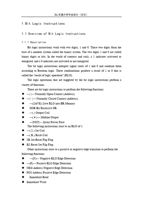
1 Bit Logic Instructions1.1 Overview of Bit Logic Instructions1.1.1 DescriptionBit logic instructions work with two digits, 1 and 0. These two digits form the base of a number system called the binary system. The two digits 1 and 0 are called binary digits or bits. In the world of contacts and coils, a 1 indicates activated or energized, and a 0 indicates not activated or not energized.The bit logic instructions interpret signal states of 1 and 0 and combine them according to Boolean logic. These combinations produce a result of 1 or 0 that is called the “result of logic operation” (RLO).The logic operations that are triggered by the bit logic instructions perform a variety of functions.There are bit logic instructions to perform the following functions:◆---| |--- Normally Open Contact (Address)◆---| / |--- Normally Closed Contact (Address)◆---(SAVE) Save RLO into BR Memory◆X OR Bit Exclusive OR◆---( ) Output Coil◆---( # )--- Midline Output◆---|NOT|--- Invert Power FlowThe following instructions react to an RLO of 1:◆---( S ) Set Coil◆---( R ) Reset Coil◆SR Set-Reset Flip Flop◆RS Reset-Set Flip FlopOther instructions react to a positive or negative edge transition to perform the following functions:◆---(N)--- Negative RLO Edge Detection◆---(P)--- Positive RLO Edge Detection◆NEG Address Negative Edge Detection◆POS Address Positive Edge Detection◆I mmediate Read◆Immediate Write1.2 ---| |--- Normally Open Contact (Address)1.2.1 Symbol<address>---| |---Parameter Data Type Memory Area Description<address>BOOL I, Q, M, L, D, T, C Checked bit1.2.2 Description---| |--- (Normally Open Contact) is closed when the bit value stored at the specified <address>is equal to "1". When the contact is closed, ladder rail power flows across the contact and the result of logic operation (RLO) = "1".Otherwise, if the signal state at the specified <address>is "0", the contact is open. When the contact is open, power does not flow across the contact and the result of logic operation (RLO) = "0".When used in series, ---| |--- is linked to the RLO bit by AND logic. When used in parallel, it is linked to the RLO by OR logic.1.2.3 Status wordBR CC1 CC0 OV OS OR STA RLO /FC writes: - - - - - x x x 11.2.4 ExamplePower flows if one of the following conditions exists:The signal state is "1" at inputs I0.0 and I0.1 Or the signal state is "1" at input I0.2.1.3 ---| / |--- Normally Closed Contact (Address)1.3.1 Symbol<address>---| / |---Parameter Data Type Memory Area Description<address>BOOL I, Q, M, L, D, T, C Checked bit1.3.2 Description---| / |--- (Normally Closed Contact) is closed when the bit value stored at the specified <address>is equal to "0". When the contact is closed, ladder rail power flows across the contact and the result of logic operation (RLO) = "1".Otherwise, if the signal state at the specified <address> is "1", the contact is opened. When the contact is opened, power does not flow across the contact and the result of logic operation (RLO) = "0".When used in series, ---| / |--- is linked to the RLO bit by AND logic. When used in parallel, it is linked to the RLO by OR logic.1.3.3 Status wordBR CC1 CC0 OV OS OR STA RLO /FC writes: - - - - - x x x 11.3.4 ExamplePower flows if one of the following conditions exists:The signal state is "1" at inputs I0.0 and I0.1 Or the signal state is "1" at input I0.21.4 XOR Bit Exclusive ORFor the XOR function, a network of normally open and normally closed contacts must be created as shown below.1.4.1 SymbolsParameter Data Type Memory Area Description<address1>BOOL I, Q, M, L, D, T, C Scanned bit<address2>BOOL I, Q, M, L, D, T, C Scanned bit1.4.2 DescriptionXOR(Bit Exclusive OR) creates an RLO of "1" if the signal state of the two specified bits is different.1.4.3 ExampleThe output Q4.0 is "1" if (I0.0 = "0" AND I0.1 = "1") OR (I0.0 = "1" AND I0.1 = "0").1.5 --|NOT|-- Invert Power Flow1.5.1 Symbol---|NOT|---1.5.2 Description---|NOT|---(Invert Power Flow) negates the RLO bit.1.5.3 Status wordBR CC1 CC0 OV OS OR STA RLO /FC writes: - - - - - - 1 x -1.5.4 ExampleThe signal state of output Q4.0 is "0" if one of the following conditions exists: The signal state is "1" at input I0.0 Or the signal state is "1" at inputs I0.1 and I0.2.1.6 ---( ) Output Coil1.6.1 Symbol<address>---( )Parameter Data Type Memory Area Description<address>BOOL I, Q, M, L, D Assigned bit1.6.2 Description---( ) (Output Coil) works like a coil in a relay logic diagram. If there is power flow to the coil (RLO = 1), the bit at location <address>is set to "1". If there is no power flow to the coil (RLO = 0), the bit at location <address>is set to "0". An output coil can only be placed at the right end of a ladder rung. Multiple output elements (max.16) are possible (see example). A negated output can be created by using the ---|NOT|--- (invert power flow) element.1.6.3 MCR (Master Control Relay) dependencyMCR dependency is activated only if an output coil is placed inside an active MCR zone. Within an activated MCR zone, if the MCR is on and there is power flow to an output coil , the addressed bit is set to the current status of power flow. If the MCR is off, a logic "0" is written to the specified address regardless of power flow status.1.6.4 Status wordBR CC1 CC0 OV OS OR STA RLO /FC writes: - - - - - 0 x - 01.6.5 ExampleThe signal state of output Q4.0 is "1" if one of the following conditions exists: The signal state is "1" at inputs I0.0 AND I0.1 OR the signal state is "0" at input I0.2.The signal state of output Q4.1 is "1" if one of the following conditions exists: The signal state is "1" at inputs I0.0 AND I0.1 OR the signal state is "0" at input I0.2 AND "1" at input I0.3If the example rungs are within an activated MCR zone:When MCR is on, Q4.0 and Q4.1 are set according to power flow status as described above.When MCR is off (=0), Q4.0 and Q4.1 are reset to 0 regardless of power flow. 1.7 ---( # )--- Midline Output1.7.1 Symbol<address>--( # )---Parameter Data Type Memory Area Description<address>BOOL I, Q, M, *L, D Assigned bit* An L area address can only be used if it is declared TEMP in the variable declaration table of a logic block (FC, FB, OB).1.7.2 Description---( # )--- (Midline Output) is an intermediate assigning element which saves the RLO bit (power flow status) to a specified <address>. The midline output element saves the logical result of the preceding branch elements. In series with other contacts,---( # )--- is inserted like a contact. A ---( # )--- element may never be connected to the power rail or directly after a branch connection or at the end of a branch. A negated ---( # )--- can be created by using the ---|NOT|--- (invert power flow) element.1.7.3 MCR (Master Control Relay) dependencyMCR dependency is activated only if a midline output coil is placed inside an active MCR zone. Within an activated MCR zone, if the MCR is on and there is power flow to a midline output coil; the addressed bit is set to the current status of power flow. If the MCR is off, a logic "0" is written to the specified address regardless of power flow status.1.7.4 Status wordBR CC1 CC0 OV OS OR STA RLO /FC writes: - - - - - 0 x - 11.7.5 ExampleM 0.0 has the RLO:M 1.1 has the RLO:M 2.2 has the RLO of the entire bit logic combination.1.8 ---( R ) Reset Coil1.8.1 Symbol<address>---( R )Parameter Data Type Memory Area Description<address>BOOL I, Q, M, L, D, T, C Reset bit1.8.2 Description---( R )(Reset Coil) is executed only if the RLO of the preceding instructions is "1" (power flows to the coil). If power flows to the coil (RLO is "1"), the specified <address>of the element is reset to "0". A RLO of "0" (no power flow to the coil) has no effect and the state of the element's specified address remains unchanged. The <address>may also be a timer (T no.) whose timer value is reset to "0" or a counter (C no.) whose counter value is reset to "0".1.8.3 MCR (Master Control Relay) dependencyMCR dependency is activated only if a reset coil is placed inside an active MCR zone. Within an activated MCR zone, if the MCR is on and there is power flow to a reset coil; the addressed bit is reset to the "0" state. If the MCR is off, the current state of the element's specified address remains unchanged regardless of power flow status.1.8.4 Status wordBR CC1 CC0 OV OS OR STA RLO /FC writes: - - - - - 0 x - 01.8.5 ExampleNetwork 1Network 2Network 3The signal state of output Q4.0 is reset to "0" if one of the following conditions exists:The signal state is "1" at inputs I0.0 and I0.1 Or the signal state is "0" at input I0.2.If the RLO is "0", the signal state of output Q4.0 remains unchanged.The signal state of timer T1 is only reset if:the signal state is "1" at input I0.3.The signal state of counter C1 is only reset if:the signal state is "1" at input I0.4.If the example rungs are within an activated MCR zone:When MCR is on, Q4.0, T1, and C1 are reset as described above.When MCR is off, Q4.0, T1, and C1 are left unchanged regardless of RLO state (power flow status).1 位逻辑指令1.1 位逻辑指令概述1.1.1 描述位逻辑指令使用两个数字,1和0。
动机可编程控制器(PLC)中英文翻译张
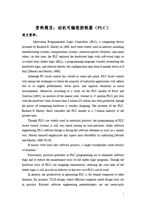
资料题目:动机可编程控制器(PLC)英文资料:Motivation Programmable Logic Controllers (PLC), a computing device invented by Richard E. Morley in 1968, have been widely used in industry including manufacturing systems, transportation systems, chemical process facilities, and many others. At that time, the PLC replaced the hardwired logic with soft-wired logic or so-called relay ladder logic (RLL), a programming language visually resembling the hardwired logic, and reduced thereby the configuration time from 6 months down to 6 days [Moody and Morley, 1999].Although PC based control has started to come into place, PLC based control will remain the technique to which the majority of industrial applications will adhere due to its higher performance, lower price, and superior reliability in harsh environments. Moreover, according to a study on the PLC market of Frost and Sullivan [1995], an increase of the annual sales volume to 15 million PLCs per year with the hardware value of more than 8 billion US dollars has been predicted, though the prices of computing hardware is steadily dropping. The inventor of the PLC, Richard E Morley, fairly considers the PLC market as a 5-billion industry at the present time.Though PLCs are widely used in industrial practice, the programming of PLC based control systems is still very much relying on trial-and-error. Alike software engineering, PLC software design is facing the software dilemma or crisis in a similar way. Morley himself emphasized this aspect most forcefully by indicating [Moody and Morley, 1999, P110]:If houses were built like software projects, a single woodpecker could destroy civilization.”Particularly, practical problems in PLC programming are to eliminate software bugs and to reduce the maintenance costs of old ladder logic programs. Though the hardware costs of PLCs are dropping continuously, reducing the scan time of the ladder logic is still an issue in industry so that low-cost PLCs can be used.In general, the productivity in generating PLC is far behind compared to other domains, for instance, VLSI design, where efficient computer aided design tools are in practice. Existent software engineering methodologies are not necessarilyapplicable to the PLC based software design because PLC-programming requires a simultaneous consideration of hardware and software. The software design becomes, thereby, more and more the major cost driver. In many industrial design projects, more than SO0/a of the manpower allocated for the control system design and installation is scheduled for testing and debugging PLC programs [Rockwell, 1999].In addition, current PLC based control systems are not properly designed to support the growing demand for flexibility and reconfigurability of manufacturing systems. A further problem, impelling the need for a systematic design methodology, is the increasing software complexity in large-scale projects.1.2 Objective and Significance of the ThesisThe objective of this thesis is to develop a systematic software design methodology for PLC operated automation systems. The design methodology involves high-level description based on state transition models that treat automation control systems as discrete event systems, a stepwise design process, and set of design rules providing guidance and measurements to achieve a successful design. The tangible outcome of this research is to find a way to reduce the uncertainty in managing the control software development process, that is, reducing programming and debugging time and their variation, increasing flexibility of the automation systems, and enabling software reusability through modularity. The goal is to overcome shortcomings of current programming strategies that are based on the experience of the individual software developer.A systematic approach to designing PLC software can overcome deficiencies in the traditional way of programming manufacturing control systems, and can have wide ramifications in several industrial applications. Automation control systems are modeled by formal languages or, equivalently, by state machines. Formal representations provide a high-level description of the behavior of the system to be controlled. State machines can be analytically evaluated as to whether or not they meet the desired goals. Secondly, a state machine description provides a structured representation to convey the logical requirements and constraints such as detailed safety rules. Thirdly, well-defined control systems design outcomes are conducive to automatic code generation- An ability to produce control software executable on commercial distinct logic controllers can reduce programming lead-time and labor cost. In particular, the thesis is relevant with respect to the following aspects.Customer-Driven ManufacturingIn modern manufacturing, systems are characterized by product and process innovation, become customer-driven and thus have to respond quickly to changing system requirements. A major challenge is therefore to provide enabling technologies that can economically reconfigure automation control systems in response to changing needs and new opportunities. Design and operational knowledge can be reused in real-time, therefore, giving a significant competitive edge in industrial practice.Higher Degree of Design Automation and Software QualityStudies have shown that programming methodologies in automation systems have not been able to match rapid increase in use of computing resources. For instance, the programming of PLCs still relies on a conventional programming style with ladder logic diagrams. As a result, the delays and resources in programming are a major stumbling stone for the progress of manufacturing industry. Testing and debugging may consume over 50% of the manpower allocated for the PLC program design. Standards [IEC 60848, 1999; IEC-61131-3, 1993; IEC 61499, 1998; ISO 15745-1, 1999] have been formed to fix and disseminate state-of-the-art design methods, but they normally cannot participate in advancing the knowledge of efficient program and system design.A systematic approach will increase the level of design automation through reusing existing software components, and will provide methods to make large-scale system design manageable. Likewise, it will improve software quality and reliability and will be relevant to systems high security standards, especially those having hazardous impact on the environment such as airport control, and public railroads.System ComplexityThe software industry is regarded as a performance destructor and complexity generator. Steadily shrinking hardware prices spoils the need for software performance in terms of code optimization and efficiency. The result is that massive and less efficient software code on one hand outpaces the gains in hardware performance on the other hand. Secondly, software proliferates into complexity of unmanageable dimensions; software redesign and maintenance-essential in modern automation systems-becomes nearly impossible. Particularly, PLC programs have evolved from a couple lines of code 25 years ago to thousands of lines of code with a similar number of 1/O points. Increased safety, for instance new policies on fire protection, and the flexibility of modern automation systems add complexity to the program design process. Consequently, the life-cycle cost of software is apermanently growing fraction of the total cost. 80-90% of these costs are going into software maintenance, debugging, adaptation and expansion to meet changing needs [Simmons et al., 1998].Design Theory DevelopmentToday, the primary focus of most design research is based on mechanical or electrical products. One of the by-products of this proposed research is to enhance our fundamental understanding of design theory and methodology by extending it to the field of engineering systems design. A system design theory for large-scale and complex system is not yet fully developed. Particularly, the question of how to simplify a complicated or complex design task has not been tackled in a scientific way. Furthermore, building a bridge between design theory and the latest epistemological outcomes of formal representations in computer sciences and operations research, such as discrete event system modeling, can advance future development in engineering design.Application in Logical Hardware DesignFrom a logical perspective, PLC software design is similar to the hardware design of integrated circuits. Modern VLSI designs are extremely complex with several million parts and a product development time of 3 years [Whitney, 1996]. The design process is normally separated into a component design and a system design stage. At component design stage, single functions are designed and verified. At system design stage, components are aggregated and the whole system behavior and functionality is tested through simulation. In general, a complete verification is impossible. Hence, a systematic approach as exemplified for the PLC program design may impact the logical hardware design.1.3 Structure of the ThesisFigure 1.1 illustrates the outline of the following thesis. Chapter 2 clarifies the major challenges and research issues, and discourses the relevant background and terminology. It will be argued that a systematic design of PLC software can contribute to higher flexibility and reconfigurability of manufacturing systems. The important issue of how to deal with complexity in engineering design with respect to designing and operating a system will be debated. The research approach applied in this thesis is introduced starting from a discussion of design theory and methodology and what can be learnt from that field.Chapter 3 covers the state-of-the-art of control technology and the currentpractice in designing and programming PLC software. The influences of electrical and software engineering are revealed as well as the potentially applicable methods from computer science are discussed. Pros and cons are evaluated and will lead to the conclusion that a new methodology is required that suffices the increasing complexity of PLC software design.Chapter 4 represents the main body of the thesis and captures the essential features of the design methodology. Though design theory is regarded as being in a pre- scientific stage it has advanced in mechanical, software and system engineering with respect to a number of proposed design models and their evaluation throughout real-world examples. Based on a literature review in Chapter 2 and 3 potential applicable design concepts and approaches are selected and applied to context of PLC software design. Axiomatic design is chosen as underlying design concept since it provides guidance for the designer without restriction to a particular design context. To advance the design concept to PLC software design, a formal notation based on statechart formalism is introduced. Furthermore, a design process is developed that arranges the activities needed in a sequential order and shows the related design outcomes.In Chapter 5, a number of case studies are given to demonstrate the applicability of the developed design methodology. The examples are derived from a complex reference system, a flexible assembly system. The achieved insights are evaluated in a concluding paragraph.Chapter 6 presents the developed computerized design tool for PLC software design on a conceptual level. The software is written in Visual Basic by using ActiveX controls to provide modularity and reuse in a web-based collaborative programming environment. Main components of the PLC software are modeling editors for the structural (modular) and the behavioral design, a layout specification interface and a simulation engine that can validate the developed model.Chapter 7 is concluding this thesis. It addresses the achievements with respect to the research objectives and questions. A critical evaluation is given alongside with an outlook for future research issues.中文翻译:动机可编程控制器(PLC),计算设备的发明人理查德e.莫莉1968年已被广泛应用于工业,包括制造系统,运输系统,化工设备等,不胜枚举. 当时,临立会取代hardwiredlogic软连线逻辑或所谓梯形图(左) 编程语言和视觉类似hardwired逻辑并因而减少了配臵时间从6个月至6天[24,000莫莉,1999].虽然基于PLC 控制已经开始进入的地方, 基于PLC的控制仍将技术中的大部分工业应用将坚持由于其较高性能,而且价格低廉,和优越的可靠性,在恶劣的环境中. 此外,根据一项研究PLC市场的霜冻和苏利文[1995], 增加的年销售量为15万PLCs每年提供硬件价值超过8亿美元,已预言,尽管价格计算硬件正在稳步下降. 发明者的临立会,理查德e莫莉, 认为公平的PLC市场为50亿元的产业在当前时间. 虽然PLCs被广泛应用于工业实践, 编程控制器的控制系统仍然非常依赖试错. alike软件工程,PLC的软件设计,目前正面临两难的软件危机或以类似的方式. 莫莉强调自己在这方面最有力的说明[穆迪和莫莉,1999年,第110]:如果楼房像软件项目,一个单一的啄木鸟可以摧毁文明. 尤其是, 实际问题可编程才能消除软件错误,以减少维修费用的老梯子逻辑节目. 虽然硬件成本PLCs正在不断下降, 减少扫描时间梯形图仍然是一个问题,在业,使低成本PLCs可用. 在一般情况下,生产力的PLC发电是落后于其他领域,例如VLSI设计那里有效率的计算机辅助设计工具的作法. 现有的软件工程方法,不一定适用于PLC的软件设计,因为PLC的编程需要同时考虑硬件和软件. 软件设计变得,因此,越来越多的主要成本动因. 在许多工业设计项目,用于控制系统的设计与安装,预计进行测试和调试PLC程序〔40998,1999〕. 此外, 当前PLC的控制系统是不恰当的设计,以支持日益增长的需求弹性和可重构制造系统. 另外一个问题,推动需要有一个系统的设计方法论,是不断增加的软件复杂的大型项目. 1.2目的和意义论文的目的这一论断,是建立一个有系统的软件设计方法可编程操作自动化系统. 设计方法涉及高层次的描述基于国家转型模式处理自动化控制系统为离散事件系统, 分步设计过程,并订定设计规则提供指导和测量,以建立一个成功的设计. 有形的结果,这项研究是为了找到一个方法,以减少不确定性,在管理控制软件发展过程中,即减少编程和调试的时间,它们的变化,越来越灵活的自动化系统并使软件的重用,通过模块. 其目的是为了克服目前的规划策略,是基于经验的个人软件开发商.一个有系统的方法来设计PLC的软件可以克服的缺陷,在传统的方式编程制造控制系统, 可以产生广泛影响的几个工业应用. 自动化控制系统是模拟的正式语言或,equivalently,由国家机器. 正式交涉,提供一个高层次的描述系统的行为被控制. 国家机器可以分析评价,以查明他们是否达到预期目标. 其次, 状态机的描述提供了一种结构性的代表转达的合理要求和制约因素,如详细的安全规则. 第三, 明确界定的控制系统的设计成果,有利于代码自动生成一个有能力生产控制软件可执行商业鲜明的逻辑控制可以减少编程的筹备时间及人力成本. 特别是,论文是有关对以下几方面. 客户导向的制造业,在现代制造系统的特点是产品和工艺创新, 成为客户导向的,因而很快地回应变化的系统要求. 一个重大的挑战就是要提供有利的技术,可以在经济reconfigure自动化控制系统,以回应变动需求和新的机遇. 设计和操作知识,可以重复使用的实时性,因此,给予相当大的竞争力,工业实践. 更高程度的自动化设计和软件质量的研究显示,编程方法自动化系统尚未能赶上急速增加,使用电脑资源. 比如,编程PLCs仍依靠传统的节目风格,梯形逻辑图. 由于延误和资源规划的一大绊脚石的进步制造业. 测试和调试可能消耗超过50%的统筹分配给PLC程序设计. 标准电工60848,1999年; 国际电工委员会61131-3,1993年;IEC61499标准,1998年;ISO15745-1, [1999]已形成固定和传播国家-国际艺术设计的方法, 但他们通常不能参与推进知识有效的计划和制度设计. 有系统的方式会增加设计水平的自动化,通过重用现有软件组件, 并将提供方法,使大规模的制度设计管理. 同样的,这将提高软件的质量和可靠性,将相关的系统高安全标准特别是那些有危害的环境影响,如机场的控制,以及公共铁路. 系统复杂的软件业,被视为表现破坏者和复杂发生器. 不断缩小的硬件价格有所斩获,需要软件的表现而言,代码优化和效益. 结果是,庞大而低效率的软件代码,一方面保持收益硬件性能另一方面. 其次,软件proliferates变成复杂到无法控制的程度; 软件重新设计并维持必要的现代自动化系统变得几乎不可能. 尤其PLC程序已从几行代码是25年前为上千行代码类似数目的算点. 提高安全性,比如新政策对防火而灵活的现代自动化系统加上复杂的程序设计过程. 因此,生命周期的软件成本,是一项长期生长所需的全部费用.80-90%这些费用都进入软件维修、调试, 改造和扩建,以满足不断变化的需求[蒙斯etal. ,1998].设计理论发展的今天,首要重点大部分设计开发研究,是基于机械和电器产品. 其中的副产品,这项研究是为了提高我们的基本了解设计理论和方法扩大到该领域的工程系统设计. 一个制度设计的理论,进行大规模而复杂的制度尚未完全建立. 尤其至于如何简化复杂或复杂的设计任务,尚未解决的一个科学的方法. 此外, 建设桥梁设计理论和最新成果的认识论的正式交涉,在计算机科学和运筹学如离散事件系统建模,可以促进未来的发展,工程设计. 应用在逻辑硬件设计,从逻辑的角度来看, PLC的软件设计类似的硬件集成电路设计. 现代超大规模集成电路设计是非常复杂的数百万件,产品开发时间为3年,[云妮,1996]. 设计过程通常是分离成组件设计和系统设计阶段. 在构件设计阶段,单一功能的设计和论证. 在系统设计阶段,部件的整理和整个系统的性能和功能测试,通过模拟. 一般来说,一个完整的验证是不可能的. 因此,一个系统的方法,如对PLC 的程序设计可能会影响到逻辑的硬件设计. 1.3结构的论文图1.1显示提纲以下论文. 第二章阐明了重大的挑战和问题进行研究,并论述了有关的背景和术语.有人会争辩说,一个系统的设计PLC的软件能有助于更高的灵活性和可重构制造系统. 重要的问题,就是如何处理复杂的工程设计等方面的设计和营运体系将辩论. 研究方法适用于这个论断是介绍从讨论设计理论和方法是什么可以从这一领域. 第三章涵盖了美国最先进的控制技术和当前的实践在设计和PLC编程软件. 影响电气和软件工程所揭示以及可能适用的方法,由计算机科学讨论. 利弊的评价,并会导致一个结论,即一种新的方法,是需要足够的面对日趋复杂的PLC软件设计. 第四章占主体的论断,抓住了本质特征的设计方法. 虽然设计理论视为处于前科学阶段,它有先进的机械, 软件和系统工程方面的一些建议的设计模式及其评价整个真实世界的例子. 根据文献,在第2和第3潜在适用的设计理念和方式的选择和应用语境PLC的软件设计. 公理化设计选定为基本设计理念,因为它提供了指导设计师不受任何限制某一设计方面. 提前设计概念PLC的软件设计,一个正式的五线谱基于状态形式主义介绍. 此外, 设计过程中,开发整理活动需要有优先顺序,显示了相关设计成果. 在第五章,增加了一些个案研究结果充分显示了适用性的开发设计方法. 这些例子都是从一个复杂的参考系统,以及灵活的组装系统. 所取得的见解评价结论段落. 第6章介绍先进的计算机设计工具,PLC的软件设计概念层次. 该软件是在VisualBasic中使用控件提供模块化和重用Web的协作编程环境. 其主要组成部分的PLC软件建模编辑结构(单元)与行为设计版面规格接口和模拟引擎,可以验证开发的模式. 第七章是结论性的论断. 它涉及的成就方面的研究目标和问题. 一个批判的评价是一起展望未来研究的问题.。
控制系统PLC英文翻译

控制系统P L C英文翻译-CAL-FENGHAI.-(YICAI)-Company One1Programmable Logic Controllers (PLCs)1 。
About Programmable Logic Controllers (PLCs)PLCs (programmable logic controllers) are the control hubs for a wide variety of automated systems and processes. They contain multiple inputs and outputs that use transistors and other circuitry to simulate switches and relays to control equipment. They are programmable via software interfaced via standard computer interfaces and proprietary languages and network options.Programmable logic controllers I/O channel specifications include total number of points, number of inputs and outputs, ability to expand, and maximum number of channels. Number of points is the sum of the inputs and the outputs. PLCs may be specified by any possible combination of these values. Expandable units may be stacked or linked together to increase total control capacity. Maximum number of channels refers to the maximum total number of input and output channels in an expanded system. PLC system specifications to consider include scan time, number of instructions, data memory, and program memory. Scan time is the time required by the PLC to check the states of its inputs and outputs. Instructions are standard operations (such as math functions) available to PLC software. Data memory is the capacity for data storage. Program memory is the capacity for control software.Available inputs for programmable logic controllers include DC, AC, analog, thermocouple, RTD, frequency or pulse, transistor, and interrupt inputs. Outputs for PLCs include DC, AC, relay, analog, frequency or pulse, transistor, and triac. Programming options for PLCs include front panel, hand held, and computer.Programmable logic controllers use a variety of software programming languages for control. These include IEC 61131-3, sequential function chart (SFC), function block diagram (FBD), ladder diagram (LD), structured text (ST), instruction list (IL), relay ladder logic (RLL), flow chart, C, and Basic. The IEC 61131-3 programming environment provides support for five languages specified by the global standard: Sequential Function Chart, Function Block Diagram,Ladder Diagram, Structured Text, and Instruction List. This allows for multi-vendor compatibility and multi-language programming. SFC is a graphical language that provides coordination of program sequences, supporting alternative sequence selections and parallel sequences. FBD uses a broad function library to build complex procedures in a graphical format. Standard math and logic functions may be coordinated with customizable communication and interface functions. LD is a graphic language for discrete control and interlocking logic. It is completely compatible with FBD for discrete function control. ST is a text language used for complex mathematical procedures and calculations less well suited to graphical languages. IL is a low-level language similar to assemblycode. It is used in relatively simple logic instructions.Relay Ladder Logic (RLL), or ladder diagrams, is the primary programming language for programmable logic controllers (PLCs). Ladder logic programming is a graphical representation of the program designed to look like relay logic.Flow Chart is a graphical language that describes sequential operations in a controller sequence or application. It is used to build modular, reusable function libraries.C is a high level programming language suited to handle the most complex computation, sequential, and data logging tasks. It is typically developed and debugged on a PC.BASIC is a high level language used to handle mathematical, sequential, data capturing and interface functions.Programmable logic controllers can also be specified with a number of computer interface options, network specifications and features.PLC power options, mounting options and environmental operating conditions are all also important to consider.2 。
机械工程及自动化专业外文翻译--PLC简介

外文原文:Introductions to PLCA PLC(i.e. Programmable Logic Controller)is a device that was invented to replace the necessary sequential relay circuits for machine control. The PLC works by looking at its inputs and depending upon their state, turning on/off its outputs. The user enters a program, usually via software or programmer, that gives the desired results.PLCs are used in many “real world”applications. If there is industry present, chances are good that there is a PLC present. If you are involved in machining, packaging, material handling, automated assembly or countless other industries, you are probably already using them. If you are not, you are wasting money and time. Almost any application that needs some type of electrical control has a need for a PLC.For example, let’s assume that when a switch turns on we want to turn a solenoid on for 5 seconds and then turn it off regardless of how long the switch is on for. We can do this with a simple external timer. But what if the process included 10 switches and solenoids? We would need 10 external timers. What if the process also needed to count how many times the switch individually turned on? We need a lot of external counters.As you can see, the bigger the process the more of a need we have for a PLC. We can simply program the PLC to count its inputs and turn the solenoids on for the specified time.We will take a look at what is considered to be the “top 20” PLC instructions. It can be safely estimated that with a firm understanding of these instructions one can solve more than 80%of the applications in existence.That’s right,more than 80%! Of course we’ll learn more than just these instructions to help. You solve almost ALL your potential PLC applications.The PLC mainly consists of a CPU, memory areas, and appropriate circuits to receive input/output data, as shown in Fig.19.1.We can actually consider the PLC to be a box full of hundreds or thousands of separate relays, counters, timers and data storage locations. Do these counters, timers, etc. Really exist? No, t hey don’t “physically”exist but rather they are simulated and can be considered software counters, timers, etc. These internal relays are simulated through bit locations in registers.What does each part do?INPUT RELAYS-(contacts) These are connected to the outside world. They physically exist and receive signals from switches, sensors, etc.. Typically they are not relays but rather they are transistors.INTERNAL UTILITY RELAYS-(contacts) These do not receive signals from the outside world nor do they physically exist. They are simulated relays and are what enables a PLC to eliminate external relays. There are also some special relays that are dedicated to performing only one task. Some are always on while some are always off. Some are on only once during power-on and are typically used for initializing data that was stored.COUNTERS-These again do not physically exist. They are simulated counters and they can be programmed to count pulses. Typically these counters can count up, down or both up and down. Since they are simulated, they are limited in their counting speed. Some manufacturers also include high-speed counters that are hardware based. We can think of these as physically existing. Most times these counters can count up, down or up and down.TIMERS-These also do not physically exist. They come in many varieties and increments. The most common type is an on-delay type. Others include off-delay and both retentive and non-retentive types. Increments vary from 1ms through 1s.OUTPUT RELAYS-(coils) These are connected to the outside world. They physically exist and send on/off signals to solenoids, lights, etc. They can be transistors, relays, or triacs depending upon the model chosen.DATA STORAGE-Typically there are registers assigned to simply store data. They are usually used as temporary storage for math or data manipulation. They can also typically be used to store data when power is removed from the PLC. Upon power-up they will still have the same contents as before power was removed. Very convenient and necessary!A PLC works by continually scanning a program. We can think of this scan cycle as consisting of 3 important steps, as shown in Fig. 19.2. There are typically more than 3 but we can focus on the important parts and not worry about the others. Typically the others are checking the system and updating the current internal counter and timer values.Step 1-CHECK INPUT STATUS-First the PLC takes a look at each input to determine if it is on or off. In other words, is the sensor connected to the first input on?How about the second input? How about the third… It records this data into its memory to be used during the next step.Step 2-EXECUTE PROGRAM-Next the PLC executes your program one instruction at a time. Maybe your program said that if the first input was on then it should turn on the first output. Since it already knows which inputs are on/off from the previous step, it will be able to decide whether the first output should be turned on based on the state of the first input. It will store the execution results for use later during the next step.Step 3-UPDATE OUTPUT STATUS-Finally the PLC updates the status of the outputs. It updates the outputs based on which inputs were on during the first step and the results of executing your program during the second step. Based on the example in step 2 it would now turn on the first output because the first input was on and your program said to turn on the first output when this condition is true.After the third step the PLC goes back to step one and repeats the steps continuously. One scan time is defined as the time it takes to execute the 3 steps listed above. Thus a practical system is controlled to perform specified operations as desired.中文译文:PLC简介PLC(既可编程控制器)是机械控制中为替代必要的继电器时序电路而发明的一种设备。
- 1、下载文档前请自行甄别文档内容的完整性,平台不提供额外的编辑、内容补充、找答案等附加服务。
- 2、"仅部分预览"的文档,不可在线预览部分如存在完整性等问题,可反馈申请退款(可完整预览的文档不适用该条件!)。
- 3、如文档侵犯您的权益,请联系客服反馈,我们会尽快为您处理(人工客服工作时间:9:00-18:30)。
Programmable Logic Controllers (PLCs)1 。
About Programmable Logic Controllers (PLCs)PLCs (programmable logic controllers) are the control hubs for a wide variety of automated systems and processes. They contain multiple inputs and outputs that use transistors and other circuitry to simulate switches and relays to control equipment. They are programmable via software interfaced via standard computer interfaces and proprietary languages and network options.Programmable logic controllers I/O channel specifications include total number of points, number of inputs and outputs, ability to expand, and maximum number of channels. Number of points is the sum of the inputs and the outputs. PLCs may be specified by any possible combination of these values. Expandable units may be stacked or linked together to increase total control capacity. Maximum number of channels refers to the maximum total number of input and output channels in an expanded system. PLC system specifications to consider include scan time, number of instructions, data memory, and program memory. Scan time is the time required by the PLC to check the states of its inputs and outputs. Instructions are standard operations (such as math functions) available to PLC software. Data memory is the capacity for data storage. Program memory is the capacity for control software.Available inputs for programmable logic controllers include DC, AC, analog, thermocouple, RTD, frequency or pulse, transistor, and interrupt inputs. Outputs for PLCs include DC, AC, relay, analog, frequency or pulse, transistor, and triac. Programming options for PLCs include front panel, hand held, and computer.Programmable logic controllers use a variety of software programming languages for control. These include IEC 61131-3, sequential function chart (SFC), function block diagram (FBD), ladder diagram (LD), structured text (ST), instruction list (IL), relay ladder logic (RLL), flow chart, C, and Basic. The IEC 61131-3 programming environment provides support for five languages specified by the global standard: Sequential Function Chart, Function Block Diagram,Ladder Diagram, Structured Text, and Instruction List. This allows for multi-vendor compatibility and multi-language programming. SFC is a graphical language that provides coordination of program sequences, supporting alternative sequence selections and parallel sequences. FBD uses a broad function library to build complex procedures in a graphical format. Standard math and logic functions may be coordinated with customizable communication and interface functions. LD is a graphic language for discrete control and interlocking logic. It is completely compatible with FBD for discrete function control. ST is a text language used for complex mathematical procedures and calculations less well suited to graphical languages. IL is a low-level language similar to assemblycode. It is used in relatively simple logic instructions. Relay Ladder Logic (RLL), or ladder diagrams, is the primary programming language for programmable logic controllers (PLCs). Ladder logic programming is a graphical representation of the program designed to look like relay logic. Flow Chart is a graphical language that describes sequential operations in a controller sequence or application. It is used to build modular, reusable function libraries. C is a high level programming language suited to handle the most complex computation, sequential, and data logging tasks. It is typically developed and debugged on a PC. BASIC is a high level language used to handle mathematical, sequential, data capturing and interface functions.Programmable logic controllers can also be specified with a number of computer interface options, network specifications and features. PLC power options, mounting options and environmental operating conditions are all also important to consider.2 。
INTRODUCTIONFor simple programming the relay model of the PLC is sufficient. As more complex functions are used the more complex VonNeuman model of the PLC must be used. A VonNeuman computer processes one instruction at a time. Most computers operate this way, although they appear to be doing many things at once. Consider the computer components shown in Figure 1.Figure 1 1 Simplified Personal Computer ArchitectureInput is obtained from the keyboard and mouse, output is sent to the screen, and the disk and memory are used for both input and output for storage. (Note: the directions of these arrows are very important to engineers, always pay attention to indicate where information is flowing.) This figure can be redrawn as in Figure 2 to clarify the role of inputs and outputs.Figure 2 An Input-Output Oriented ArchitectureIn this figure the data enters the left side through the inputs. (Note: most engineering diagrams have inputs on the left and outputs on the right.) It travels through buffering circuits before it enters the CPU. The CPU outputs data through other circuits. Memory and disks are used for storage of data that is not destined for output. If we look at a personal computer as acontroller, it is controlling the user by outputting stimuli on the screen, and inputting responses from the mouse and the keyboard.A PLC is also a computer controlling a process. When fully integrated into an application the analogies become;inputs - the keyboard is analogous to a proximity switchinput -circuits - the serial input chip is like a 24Vdc input cardcomputer - the 686 CPU is like a PLC CPU unitoutput - circuits - a graphics card is like a triac output cardoutputs - a monitor is like a lightstorage - memory in PLCs is similar to memories in personal computersIt is also possible to implement a PLC using a normal Personal Computer, although this is not advisable. In the case of a PLC the inputs and outputs are designed to be more reliable and rugged for harsh production environments.3 。