高精度50KHZ
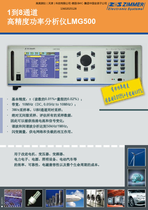
zimmer_lmg500功率分析仪技术参数
变压器、电感器和电容器 在最低功率因数下的损耗
延迟时间菜单,设定有1、2、3相电流补偿值
功率测量到10MHz要求电压和电流通道设计成相互之间延迟要非常小,LMG500延迟小于3ns, 意味着相角误差在50Hz时<1 µ弧度,因为LMG500包含有这种特色,所以它是最适合测量变压 器、电感器和电容器在非常低功率因数下的功率损耗。标配就能完全满足这些测量需求,不需 要选件。
因此可以捕获浪涌电流和信号变化; · 谐波和间谐波分析达到50kHz/1MHz; · 闪变测量,供电网络和负载的相互作用。
用于改进电机、变压器、变频器、 电力电子、电源、照明设备、电动汽车等 的效率、可靠性、电磁兼容性以及整个生命周期的成本。
LMG500 e 02.10
LMG—高精度功率测量的代名词
多绕组变压器
没有传动装置的风力发电机, 但是带有扩展的旋转速度量程 定子侧频率固定,通过设定转 子侧的频率,双反馈机器可以 像发电机一样在不用风速下高 效率地工作。
一次侧 u1
U1 U5 v1 w1
12脉冲整流变压器的8通道测量
整流侧 u2
v2 U2
U4
w2 U3
u3
v3 U6
U8
w3 U7
三绕组变压器,带有两个30°电子档位输出线圈,提供两个6脉冲 整流器。因此,初级线圈抑制谐波,如5次、7次、17次、19次谐波。 功率测量通道被配置成两组,通道1和5并联,所以所有的测量 通道都有相同的参考相位。相角偏移(n.30°)的特殊整流变压器 可以被准确测量。
变频器 输出端的瞬态电流
通过10MHz的高带宽,可以采样和显示 变频器输出端的高频电流峰值。 瞬态电流峰值产生在每一次开关变换的 边缘。电流流经绕组电容,它们产生一 个数倍于额定电流的峰值。 可以从客户菜单的显示中得到Ipp1和Itrms1 的高比值。
高精度宽带宽高稳定性的电流传感器测量技术

技术文章Technical Article高精度,高带宽,高稳定性的电流传感器测量技术池田健太,增田秀和1前言当今,在功率调节器和变频器等功率转换系统所代表的电力电子领域中,大家对电流都有着高精度,高带宽的测量需求。
我司自从1971年发售了钳形测试仪CT-300(Fig.1)以后,一直以来根据不同的测量用途,提供着各种各样的电流传感器(Fig.2)。
在本稿中,我们聚焦高精度,高带宽的电流测量需求,对我司的电流传感器的特长以及电流测量的要点做一个记述。
若您有需求,请致电与我们联系!400-808-62552关于电流传感器的检测方式电流传感器的检测方式虽然涉及到多方多面,但大多数的方式,都是由被测导体中流过的电流在磁力铁芯中产生磁通量,然后插入钳表空隙时,通过磁电转换元件或者在磁力铁芯上缠绕的线圈来进行检测的。
而每种检测方式,都有它的优点和缺点。
所以用1种检测方式,去应对所有的测量需求是非常困难的。
我司把2种检测方式进行了组合,我们称它为零磁通方式(也被称作闭环方式或磁力平衡方式)。
通过采用这种方式,我们提供着高精度,高带宽的电流传感器。
零磁通方式,就如Fig.3,4中所示要形成包含了磁力电路的负反馈电路。
而为了能够抵技术文章Technical Article消被测电流在铁芯中所产生的磁通量,在反馈线圈中也会流过电流。
因为运行的磁通量可以控制的非常小,所以其优势在于受到磁性材料的非线形性的影响可以抑制在最低限度。
我司的高精度电流传感器使用的就是由Fig.3中所示的磁通门方式和变流器(CT)方式组合之后的零磁通方式。
磁通门方式可以从直流开始测量,因其检测用的不是半导体,所以失调电压较小,在温度稳定性,长期稳定性上都有很卓越的表现。
我司提供的电流传感器精度为0.02%rdg,频宽3.5MHz,其精度和频宽都是世界顶尖水准。
另外,我们灵活利用了磁通门方式在高温下的稳定性,还提供了可以在-40°C~+85°C温度环境下测量的产品。
德国ACAM公司产品
脉冲数
2 x 4, 1 x 8 1x4
1x4 1x3
1x4 1x3
封装图
TQFP 44 Package 1.2 mm
12 mm 10 mm
Original Size
12 mm 10 mm
0.8 mm 0.35 mm
7
1.3 TDC-GP2
总述
特性
TDC—GP2是acam通用TDC的新一代产品。更高的分辨 率和更小的封装,使得它尤其适合于对成本比较敏感 的应用。GP2还具有脉冲产生器,STOP使能,温度测 量和时钟控制等特殊功能块,完全适合于超声波流量 测量和热量测量。
4. PICOTURN-涡轮增压器转速测试仪
4.1 PICOTURN-第一代产品 4.2 PICOTURN-第二代产品
5. 联系方式
页码 4
4 6 8 10 12 14
16
16 18 20 22 24 25 26 27
28
28 30 32 33
34
34 36
38
1.1 时间数字转换器 (TDCs)
越来越多的领域以高精度的时间测量为基础。这些领 域所要求的飞行时间测量分辨率通常小于1ns,在很 多领域甚至只有几个皮秒。时间测量遍及工业,汽 车,医学和科研领域。这些客户要求具有高精度,小 体积,低成本和商业化等综合因素的经济型解决方 案。
acam公司的时间数字转换器(缩写是TDC)为这些系 统提供了理想的平台。全数字化的集成电路以时间延 迟为基础,用标准CMOS工艺来制造。对温度和电压 变化的补偿方法,保证了测量结果的高稳定性和可靠 性。与模拟测量方法相比,数字化TDC的主要优势就 在于高测量频率,优秀的测量分辨率和低功耗.
2. PICOSTRAIN-革新应变电阻测量尖端
解读测试设备的精度指标

对于采用互感器的工频电机试验,由于互感 器检定规程已对相位进行严格规定,用户即便不 考虑相位指标,在功率因数较高的境况下,相位 的影响可以忽略,当功率因数较低时,可采用低 功率因数表提高仪表的相位精度,并采用更高准 确度等级的互感器,提高传感器相位精度。
《GB/T 1032-2005 三相异步电动机试验方 法》附录 A 中明确指出,功率测量的相角误差包 括:
0.08% (0.03%rdg +0.05%f.s)
0.1% (0.05rdg + 0.05%f.s)
0.58%
1.1%
(滤波器+0.5%) (滤波器+1%)
0.28%
0.4%
(滤波器+0.2%) (滤波器+0.3%)
0.04% (0.01%rdg + 0.03%f.s)
0.06% (0.02%rdg +0.04%f.s)
事实上,对于采用量程表示精度的仪表而言, 在量程范围内,被测值(真值)越小,读数越小, 相对误差越大,相对误差与真值的关系如下图, 图中,仪表准确度为 0.2 级,真值在量程的 1/128~1(0.78125%~100%)之间,为表示方便, Y 轴采用对数刻度,由图可知,当真值在量程附 近,最大相对误差接近 0.2%,真值在量程的 1/128 倍时,最大相对误差为 25.6%。
1)功率表电压线圈回路的相角误差; 2)电流互感器的相角误差; 3)电压互感器的相角误差。 附录 A 还对相角误差的提出了有效的修正方 法。 对于变频测试而言,互感器不再适用,选用 其它传感器时,必须考虑相位误差对功率测试的 影响。以霍尔电压传感器为例,其相位误差一般 不在技术文档中出现,但是,可以由上升时间 tr 或上限频率 fH 通过时域或频域分析进行粗略估 算。
LK-G基恩士激光测头

ABLE可以对激光发射时间、激光功 率以及增益(CCD放大系数)这三 种要素进行智能控制。 *ABLE= ACTIVE BALANCED
LASER CONTROL ENGINE (活动平衡激光控制引擎)
Li-CCD
在精确度,速度和灵敏度方 面具有更高层次的表现。
高精度物镜单元
结合了感测头的高精度Ernostar 物镜能够实现高精度高稳定性的 测量。
LK-G35 850µm 30µm
LK-G85 1100µm
70µm
LK-G155 1700µm 120µm
LK-G405 8300µm 290µm
LK-G505 9500µm 300µm
小光点型
经过现场应用验证的设计概念
IP67 级别
即使在一些容易溅到水的场所或其它地方, 本产品出色的防水结构使得其也能正常使用。
滤光镜
转移的聚焦点 表面反射造成的衰减 滤光镜和光轴的角度造成的折射
*LK-G155/G405/G505系列
50kHz的超高采样速度
比传统型号快25倍的高速采样是Li-CCD的一大特色。由专用波 形处理器(数字信号处理器)对发自Li-CCD的信号进行高速数字 处理,能够满足高速测量和高精度测量的要求。可以对高速移动, 高速转动或高速振动的物体进行可靠的测量。
检测HDD的偏转
±0.02%的高精确度
KEYENCE 对光学系统进行重新设计,以实现高精度的测量。 Ernostar光学系统和Li-CCD的结合能够产生极为出色的线性特性。 它精确地聚焦/检测到来自目标的反射,以此提供两倍于常规型号 的精度。因此,LK-G系列被设计用于产品小型化和高精度测量。
测量硅晶片的厚度
测量PCB的变形
雷尼绍xl30激光干涉仪仪器清单
雷尼绍xl30激光干涉仪仪器清单摘要:1.雷尼绍xl30 激光干涉仪的概述2.雷尼绍xl30 激光干涉仪的测量性能3.雷尼绍xl30 激光干涉仪的优点4.雷尼绍xl30 激光干涉仪的应用领域5.结论正文:一、雷尼绍xl30 激光干涉仪的概述雷尼绍xl30 激光干涉仪是一种高精度的测量仪器,它利用激光干涉技术来测量物体的线性尺寸和角度。
该仪器具有高精度、高稳定性和快速测量等特点,广泛应用于工业生产、科学研究、航空航天等领域。
二、雷尼绍xl30 激光干涉仪的测量性能雷尼绍xl30 激光干涉仪具有以下测量性能:1.高精度:该仪器的测量精度可以达到0.5ppm,即0.0005%,可以满足高精度测量的需求。
2.高稳定性:该仪器具有稳定的激光源和准确的环境补偿,可以在各种环境下进行高精度测量。
3.快速测量:该仪器的最高测量速度可以达到4m/s,最高数据记录速率可以达到50kHz,可以满足高速测量的需求。
4.高分辨率:该仪器的线性分辨率可以达到1 纳米,可以进行高精度的测量。
三、雷尼绍xl30 激光干涉仪的优点雷尼绍xl30 激光干涉仪具有以下优点:1.体积小:该仪器的体积小,重量轻,便于携带和使用。
2.测量范围广:该仪器可以测量各种线性尺寸和角度,适用于各种测量需求。
3.操作简单:该仪器的操作简单,不需要特殊的技能和培训,可以快速上手。
4.维护方便:该仪器的维护方便,使用寿命长,可以降低维护成本。
四、雷尼绍xl30 激光干涉仪的应用领域雷尼绍xl30 激光干涉仪广泛应用于以下领域:1.工业生产:该仪器可以用于测量零件的尺寸和形状,确保产品质量和生产效率。
2.科学研究:该仪器可以用于测量实验样品的尺寸和形状,提高实验数据的准确性。
3.航空航天:该仪器可以用于测量航空航天器的尺寸和形状,确保飞行安全和性能。
全球高精度音频微波电子产品说明书
71MXL LARGE DIAPHRAGM CONDENSER STUDIO MICS Studio condenser microphones with both FET and tube circuitry available. FET models require 48V phantom power, while tube models include power supply.ITEM DESCRIPTIO N PRICE MXL-770...............Cardioid, 6-micron 20mm gold-sputtered diaphragm FET w/shockmount and case,30Hz-20kHz, -10dB pad and bass roll off .................................................................................................89.95 MXL-2003.............Cardioid transformerless condenser w/bass cut and -10dB pad switches, 20Hz-20kHz ........................169.95 PRO-PAC-PLUS+..MXL2003 & MXL603S (transformerless cardioid instrument mic),w/shockmounts, cables, windscreens in padded case ............................................................................279.95 MXL-2006.............Cardioid, true Class 'A' FET preamp w/balanced transformerlessoutput, high-isolation shockmount and case, 30Hz-20kHz .......................................................................99.95 MXL-2010.............3-pattern (cardioid/Figure-8/omni) capsule, FET preamp w/bassroll-off switch, shockmount & windscreen, 30Hz-20kHz .........................................................................169.95 MXL-CUBE............Drum condenser cardioid mic, FET balanced output w/mic clip, 20Hz-20khz ...........................................99.95 MXL-GOLD-35.......Gold-plated cardioid condenser w/shockmount, leather case, windscreen, 20Hz-20kHz ........................695.00 MXL-M3................Cardioid condenser, transformer balanced output, FET preamp, 20Hz-23kHz ........................................249.00 MXL-R77 ..............Classic body Figure-8-patterned ribbon condenser w/wood case,desktop stand, & 25ft XLR cable, 20Hz-18kHz .......................................................................................399.99 MXL-R77-L...........Same as above, but w/custom Swedish Lundahl transformer ................................................................549.95 MXL-R144 ............Figure-8 patterned ribbon condenser, purple & chrome finishw/shockmount, case, cleaning cloth, 20Hz-17kHz ....................................................................................99.99 MXL-TROPHY........Cardioid condenser w/side-tapped capsule & removable nameplate, 20Hz-20kHz ................................199.95 MXL-V6.................Cardioid mic w/balanced FET output stage, case, & clip, 20Hz-20kHz ...................................................299.00 MXL-V67G ............Transformer-balanced cardioid mic w/solid-state preamp & gold grill, 30Hz-20kHz .............................119.95 MXL-V67I .............Same as above but w/2 selectable 1" cardioid capsules (one bright, one warm) & -10dB pad switch ..169.95 MXL-V67Q ............X/Y stereo pattern condenser mic, w/gold-plated grill, 2 externally biased 22mm pressuregradient capsules, 10ft custom XLR cable, 20Hz-20kHz ........................................................................199.95 MXL-V69-MOGAMI-EDITNTransformerless tube cardioid condenser w/shockmount, power supply, 15ft 7-pin cable,15ft XLR cable, cleaning cloth, & case, 20Hz-18kHz ..............................................................................299.95 MXL-V69XM..........Same as above, but w/transformer balanced output, 20Hz-18kHz .........................................................399.00 MXL-V87...............Low-noise transformer-balanced cardioid condenser withFET preamp, w/pop filter & shockmount, 20Hz-20kHz ............................................................................299.95 MXL-V88...............Low-noise cardioid condenser w/balanced transformerless output, FET preamp,high-isolation shockmount & flight case, 20Hz-20kHz ...........................................................................199.00 MXL-V177.............Low noise classic body cardioid condenser w/6-micron thick gold-sputtered diaphragm, 20Hz-20kHz .299.95 REVELATION.........Variable pattern tube condenser mic w/EF86 pentode tube ..................................................................1295.00 GENESIS...............Tube condenser cardioid mic w/-10 dB pad, dedicated power supply ....................................................595.00R144V1772010GOLD-35GENESIS REVELATIONCUBEVIP50DC-196DC-96B72ID The RØDE NT5 is a true condenser microphone specifically two stand mounts and two windscreens. Requires 48V phantom power. Frequency dynamic range >128dB. Available in pairs, or as single RØDE NT2A MULTI-PATTERN LARGE DIAPHRAGM CO NDENSER MIC The successor to the very popular NT-2 studio condenser mic, the NT2A now has the internally shock mounted H F1 dual 1" capsule, the same as is used in the K2 microphone, and new electronics with extremely low 7dBA self-noise. It has a 3-position variable polar pattern for omni, cardioid, and figure-8 patterns, three positions of selectable attenuation (0dB, -5dB, or -10dB) and low freq. roll-off (flat, 80Hz or 40Hz). The NT-2A comes with a soft pouch and mounting clip.ITEM DESCRIPTI O N PRICE NT2A ...................Multi-pattern condenser ................399.00ID phone with an incredible 5dBA self noise figure. 48V phantom power, transformerless output, 137dB max. SPL, fixed cardioid pattern.SCHO EPS CO LETTE MODULAR MIC SETSMicrophones consist of a mic cap-sule and amplifier. The CMC 6 microphone amplifier converts extremely high-imped-ance signals from the attached capsule toa very low-impedance signal suitable for transmission via mic cable. It also featuresa symmetrical Class “A” output stage, free of coupling condensers or an output transformer. They are light-weight, have extremely low distortion, and their very low output impedance helps make them insensitive to electrical interference. The CMC 6 works with both 12V and 48V phantom powering. Matte gray options listed below but also available in nickel. All sets include SG20 stand clamps and B5 popscreens.ITEM DESCRIPTI O N PRICE CMC621G-SET ....Includes CMC 6 amplifier & MK21wide cardioid capsule ..................1632.00 CMC622G-SET ....Includes CMC 6 amplifier, & MK22 open cardioid capsule ........1632.00 CMC64G-SET ......Includes CMC 6 amplifier & MK4 cardioid capsule ..........................1542.00 CMC641G-SET ....Includes CMC 6 amplifier &MK41 supercardioid capsule ........1743.00CMC641CG-SET ..Includes CMC 6 amplifier & MK41 super-cardioid capsule, CUT 1 filter ......2320.00CMC65G-SET ......Includes CMC 6 amplifier &MK5 omni/cardioid capsule..........2059.00CMC68G-SET ......Includes CMC 6 amplifier &MK8 figure-8 capsule...................1938.00NEAR-FIELD-OMNI-STIncludes 2 CMC 6s, matched pairof MK2 omnis ...............................3150.00UNIVERSAL-OMNI-H-STIncludes 2 CMC 6s, matched pairof MK2 H omnis ............................3214.00UNIVERSAL-OMNI-S-ST ........................................................Includes 2 CMC 6s, matched pairof MK2 S omnis ............................3150.00WIDE-CARDIOID-STIncludes 2 CMC 6s, matched pairof MK21 wide cardioids ................3199.00OPEN-CARDIOID-STIncludes 2 CMC 6s, matched pairof MK22 open cardioids ...............3199.00CARDIOID-ST ......Includes 2 CMC 6s, matched pairof MK4 cardioids ..........................2999.00SUPERCARDIOID-STIncludes 2 CMC 6s, matched pairof MK41 supercardioids ...............3439.00SWITCHABLE-PATTRN-STIncludes 2 CMC 6s, matched pairof MK5 omni/cardioids ......................CALL MK21MK5MK41MK8MK22MK4NEUMANN KM180 SERIES The KM180series condensers offer the same trans-formerless circuitry as the KM100s without the 10dB pad. Frequency response is 20Hz-20kHz. The KM183, KM184 and KM185 have SPL han-dling of 140dB, 138dB and 142dB respec-tively. 48V phantom power is required.ITEM DESCRIPTI O N PRICE KM183 ................Omni condenser mic ......................899.95KM184 ................Cardioid condenser mic .................849.95KM185-SILVER ...Hypercardioid condenser mic .........899.95EA2124A .............Optional suspension mount ...........279.01WNS100 .............Replacement windscreen .................26.07WS100................Optional 90mm windscreen .............28.03SKM183-MT ........Stereo mic pair-omni,w/case, black ...............................1699.95SKM183-SILVER .Stereo mic pair-omni, w/case ......1699.95SKM184-MT ........Stereo mic pair-cardioid,w/case, black ...............................1599.95SKM184-NI .........Stereo mic pair-cardioid,w/case, nickel ..............................1599.95NEUMANN U87AI 3-PATTERNA legendary FET large diaphragmtransformer coupled studio mic withomni, cardioid and figure-8 patterns,N PRICEMXL SMALL DIAPHRAGM CONDENSER MICS These small diaphragmcondenser mics are quiet, sensitive, rugged enough for the road and inexpen-sive. They are an excellent choice for drum overheads and for close recordingof acoustic instruments. 48V phantom power required.ITEM DESCRIPTI O N PRICE MXL-603PAIR .....Stereo pair of transformerless cardioid instrument mics, 30Hz-20kHz,w/ MXL-41-603 shockmounts & case ................................................................................199.00MXL-604.............Small diaphragm cardioid condenser, 30Hz-20kHz, w/ wooden case,mounting clip and omnidirectional capsule.........................................................................83.93MXL-V67N ..........Small diaphragm instrument condenser, omni/cardioid capsules, 20Hz-20kHz ................119.95MXL-41-603 .......Replacement shockmount for MXL-603PAIR ........................................................................38.95603PAIR ID This mic sure level of 144dB, which is good forrecording amps, drums, and other loudinstruments. Acoustic instruments willbenefit from the TLM102’s fast transientresponse. The TLM102 also features a slight boostNEUMANN TLM103/TLM103D These are large diaphragm cardioid mics with a transformerless output stage. Designed primarily for vocals, the TLM03 also excels on piano, percussion, and stringed instru-ments. The TLM103D is a digital version of the mic, designed for home recording and project studios. Its A/D converter receives the output signal directly from the capsule, ensuring that the signal has no coloration and superb transparency. Both mics require 48V phantom power and come with We service many of the major brands that we carry.Call our Authorized Repair Department at ext. 1172Honesty and Valuesince 197173Thisrugged system has separate capsules and powering modulesthat can be combined to produce a wide variety of microphones.A single module and a few capsules can provide the user withflexibility that would otherwise require investing in a numberof individual microphones. It converts quickly from one type ofmicrophone to another by simply threading together varioussystem components. All capsules use back-electret technologyfor uncompromised quality. Output of all powering modules isbalanced, low impedance (200ohms) and terminates in a stan-“Universal” powering module for the sys-tem. Powered by a single 1.5V “AA” battery with a life of 150 hours, or phantom power SHURE KSM42 & KSM44A LARGE Premium side-address mics offering a dual-diaphragm design with an active front, ultra thin (2.5 micron) 24-karat gold, low mass, 1" Mylar® diaphragm. The KSM42 is ideal for vocal applications with a tailored frequency nal pop filtering. The single-pattern design exhibits smooth proximity control & ultra-wide dynamic range. An internal shock KSM42KSM44A SSED SINGLE-DIAPHRAGM For studio recording and live sound production. The KSM32 offers an extended frequency response of 20Hz-20kHz for an open, natural sound. The Class “A” transformerless preamp circuitry eliminates cross-over distortion for improved linearity across the full frequency range. mass diaphragm provides extended low frequency response and excellent transient microphones feature 20Hz-20kHz frequency response, a 3-position pad switch, a 3-position LF filter, and include a windscreen and carrying case. The KSM137 is a single pattern cardioid mic, while the KSM141 is a dual ...............................665.00 ...............................870.00 PRICE NDENSER The e614 has a super-cardioid pattern, with a neutral response and moderate sensitivity, which insures optimum isolation from other instruments on stage. Unobtrusive for precise place-ment and powered by external phantom power (P48), the e614 tolerates extremely high SPLs, precisely capturing cymbals and hi-hats better than other mics in its price range. 10-year warranty. Frequency response is 40Hz-20KHz.PRICE A large diaphragm side-address microphone with a car-dioid pickup pattern and a nickel colored finish. It has a large 1" diaphragm precisely sputtered with 24-carat gold. It has a sturdy metal housing and the elastically mounted capsule suppresses handling noise. It has a max SPL level of 140dB and a low self-noise level of 10dB(A). It has a frequency response of 20Hz-20kHz, a sensitivity rating of 25mV/Pa and a dynamic range ING SOON!99.9574at home in sound reinforcement systems or in sound studios and motion picture/ TV scoring stages. When used with the optional windscreen, the SM94 can be used by vocalists and speechmakers who desire a wide, flat z and a uniform SHURE PG27LC & PG42LC SIDE ADDRESSThese mics feature acardioid pickup pattern, large diaphragm capsules withswitchable attenuators. The PG27LC is designed for usewith instruments. It has a flat, neutral frequency responsefeatures a voice-tailored frequency response of 20Hz-20kHz as well as an SPL rating PG42LC PG27LC NDENSER ect choice for y demo tapes, les om pow-STC2OMEGA ORPHEUS STC1HELIOS STC10STC2X STC20SATURN studio environments. Features interchangeable capsules for superior versatility. The small diaphragm design provides superior audio with con-sistent, textbook polar responses and is small enough to use in the tightest conditions. The compact side-address design features an innovative lock-ing ring to provide secure connection between capsule and preamplifier. The 20Hz-20kHz frequency response is tailored for wide dynamic range applications for use in high SPL environments. Ships with stand adapter, LET DESIGN BLACK KNIGHT ID PRICE VISIT OR CALL 800-356-5844 FOR MORE INFO We have the largest selection of hard to find items. Call us!Honesty and Valuesince 197176VIOLET DESIGN PEARL SERIES CARDIOID CONDENSER These mics have a rear-ported spherical head and nar-row tapered form reflector to reduce internal resonances and optimize the cardioid polar pattern. The Pearl Standard uses a medium single-diaphragm to provide a modern,airy and detailed sound while the Grand Pearl uses a largedual-diaphragm, providing the warm, classic sound usuallyassociated with vintage studio microphones. Pearl Vocal is ahandheld stage vocal mic, and has special shockmounting forreduced handling noise, a special mid-sized capsule designedfor high gain before feedback with extended flat LF responseand outstanding dynamic range. All models include wood box and stand clip.NES These are side-addressed, cardioid, large dual diaphragm vacuum-tube studio microphones in 3 variations, with acous-tically-transparent head construction and internal shock-mounts. The 6267 vacuum tube preamplifier is a Class “A” fully-discrete circuit with massive heatsink, very high output, flat audio-response and ultra-low noise and distortion. The large custom-wound Permalloy humbucking audio trans-former adds even more “analog warmth” to the sound with wide frequency response and minimum saturation. ComesVIOLET DESIGN AMETHYST CONDENSER STUDIO MICSThe Amethyst cardioid studio microphones use fully-discrete,phantom-powered Class “A” transformerless amplifiers. TheAmethyst Standard uses a single diaphragm center-terminatedcapsule which provides modern, detailed sound with airy highs,medium vocal presence and accentuated low-end response.The Amethyst Vintage uses a dual-diaphragm, dual-backplatecapsule which provides a classic, wide-spectrum, vintage micro-phone sound. Both models have a uni-directional cardioid polarpattern with minimal proximity effect and are linear over the wide frontal incidence NDENSER MICS The Flamingo Junior series are side-addressed studio microphones that use a single-diaphragm, cardioid electrostatic transducer which provides vintage tone with transparent highs, optimized vocal presence and fundamental low-frequency register with minimal proximity effect. An integrated capsule shockmount within the head and an included external compact studio shock-mount reduce stand rumble and mechanical shocks. The custom-wound large humbucking audio transformer adds “analog warmth” to the sound. Comes - Globe features transformerless Class “A” discreet electronics, internal shockmounts for both electronics and capsule, and a spherical and acoustically transparent head design. The Globe Standard has a classic wide-spectrum sound ideal for orchestral applications. The Globe Vintage uses a different dual-diaphragm capsule providing a sweet and warm, vin-tage vocal microphone sound. Comes in a wooden box with shockmount.GLOBE-STANDARD An electrostatic multi-pattern studio mic with a vintage sound, warmed by vacuum tube circuitry and an output transformer. Features specially designed large dual-diaphragm transducer, and 9 different polar patterns. Its Class “A” fully-discrete internal vacuum tube preamp provides high output, low impedance and low distortion. A large humbucker, custom-wound audio transformer balances the microphone’s output, providing additional analog warmth to the sound. Soft starting, smart power supply and external elastic This large dual-diaphragm cardioid con-denser studio microphone has a warmer smooth tone with very high output and low noise. The fast transient response, crystal clear highs and loud SPL handling make it excellent for recording drums. The multi-layered wedge shaped brass mesh head design effectively reduces plosive sounds and breath, pop or wind noises. The internal solid state preamplifier is a Class“A” fully discrete transformerless circuit, and runs on 48V phantom power.PRICE 679.0099.00ID rating an integrated, tapered reflector which reduces resonances, removes reflections and tern. Integrated damping of the transducer reduces stand rumble, outside infrasonic FRR A compact electrostatic mic preamp body for use with vintage German-made M-series inter-changeable capsule heads, as well as B-series and VIN-seriesinterchangeable capsule heads made by JZ in Latvia. The elec-tronics are phantom powered, with a linear Class “A” discretesolid state transformerless design to provide extremely low self-noise and distortion. The Global Pre provides a low-impedance,balanced output on a gold-plated 3-pin XLR. It comes in a woodenVIN47GLOBAL-PREM COMPATIBLE。
日本日置HIOKI功率分析仪3390-10
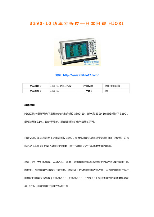
3390-10功率分析仪—日本日置H I O K I官网:/具体说明:HIOKI这次最新发售了高精度的功率分析仪3390-10。
新产品3390-10精度超过了3390,最高达到±0.1%,助力于节能、新能源相关的电气机器的开发。
日置2009年3月开发了功率分析仪3390,作为高精度的功率计受到用户的广泛使用。
这次新产品3390-10充实了功率计的种类,进一步满足了对于高精度丈量的要求。
现在,对于太阳能面板、电动汽车、马达、变频器等节能/新能源相关的电气机器的需求不断的增加。
在此类电气机器的开发现场,要求以0.1%为单位的效率改善。
这次发售的新产品主机和闭口型电流传感器(CT6862-10、CT6863-10、9709-10)组合使用的丈量精度最高可达±0.1%,非常适用于节能产品的开发。
另外,上述精度(最高±0.1%)的特点是所有量程都能保证相同。
3390会由于量程的不同而精度不同。
但是,现在所有量程保持同一精度,在丈量时候可以忽略由于量程带来的精度差异。
※精度:相对电气信号的“真值”,丈量仪器所显示的丈量值会出现什么程度的差异的指标应用马达、变频器、太阳能面板、功率调节器、电动汽车、空调等节能、新能源领域的电气机器开发。
特点∙和闭口型电流传感器组合,可实现最高±0.1%的丈量精度新产品和日置的闭口型电流传感器组合,可实现最高±0.1%的丈量精度。
3390最高仅有0.16%,现在可以进行更高精度的电流丈量。
为了开发用于节能等用途的产品,需要0.1%为单位的高精度丈量,新产品就能满足这个需求。
∙所有量程都实现同一精度3390的不同量程之间的精度会有差异,而新产品不论什么量程的精度都是同一的,这样不需要担心量程题目影响电流和功率丈量。
精度参数电压电流有功功率DC±0.07% rdg. ±0.1%f.s. ±0.07% rdg. ±0.1%f.s.±0.07% rdg. ±0.1%f.s.45 Hz ~66 Hz±0.05% rdg. ±0.05% f.s. ±0.05% rdg. ±0.05% f.s.±0.05% rdg. ±0.05% f.s.上述频率范围中以和专用电流丈量选件的组合精度而定。
横河WT5000高精度功率分析仪

7 多单元同步接口 1台主机和3台从机,总共可连接4台。
8 RGB输出 1280×800的高分辨率RGB视频信号输出
9 30A输入单元 高精度单元,支持0.5A~30A电流及1.5V~1000Vrms(1500VDC) 电压的直接输入。用户可以自行安装、移除、切换这些输入单 元。
2 10.1英寸WXGA触屏 即使周围充斥着电机、变频器等带来的高电气噪音,10.1英寸电容 触屏依然能够实现优秀的抗干扰性能。
3 显示格式设置 全面的功率分析显示功能,包括数值/波形/矢量/柱状图。
4 输入单元和量程设置键 设定多达7个输入单元的电压和电流量程。
5 存储和积分功能键 存储和积分功能设置以及执行键。
M 2
1 DC
3 DC
电池
DC 2
DC 4
M 3
配备集成 控制器的 前驱电机
M 4
案例1:带有集成控制器的现代驱动系统不允许测量交流信号。这里主要的测量任务之一是测量 从直流电到机械功率的总体驱动系统效率。此示例呈现的是4项直流电测量值(1~4)以及4项对应 的机械功率测量值(M1~M4)。
M 1
驱动轴控制器
AC 1 ... 6
6相电机 变频器
3
M
负载
AC 1 ... 6
DC DC 77
DC DC 77
同步
变频器 6相电机
AC 1 ... 6
2
M
负载
变频器 6相电机
AC 1 ... 6
4
M
负载
从机2 从机3
轻松实现精准测量
2 3
1 4 5
1 外围设备连接 两个USB端口,用于连接存储设备、键盘、鼠标等。
高精度VGA概论

MT-072
选择这些电阻是为了产生1、10、100和1000的十倍频程增益,但是,如果需要其他增益, 可以轻松更改电阻值。理想情况下,应该使用一个调整电阻网络,以获得初始增益精度和 低温漂特性。20 pF的反馈电容确保了稳定性,并在切换增益时保持输出电压不变。开关的 控制信号会先将第一个开关关闭几纳秒,然后再开启第二个开关。在此期间,运算放大器 为开环。如果没有电容,输出会开始摆动。相反,电容会在开关期间保持输出电压不变。 由于两个开关同时断开的时间非常短,因此只需要20 pF。对于较慢的开关,可能需要较大 的电容。 增益为1000时,VGA的输入电压噪声频谱密度仅为1.65 nV/√Hz (1 kHz),略高于仅使用AD797 时的噪声性能。出现增加的原因在于ADG412的噪声以及流过RON的AD797电流噪声。 VGA的精度对于决定系统整体精度非常重要。AD797的偏置电流为0.9µA,流过35 Ω RON时, 结果会额外导致31.5 µV的失调误差。与AD797的失调相加后,总VOS变为71.5 µV(最大值)。 失调温度漂移受偏置电流和 R ON变化的影响。计算显示,总温度系数从 0.6 µV/ºC 增加至 1.6 µV/ºC。请注意,尽管这些误差很小(最后可能无关紧要),但仍然需要知道它们的存在。 在实际应用中,电路精度和增益TC将由外部电阻决定。共模范围、输入偏置电流等输入 特性完全取决于AD797。 DAC编程VGA 另一种VGA结构在运算放大器的反馈环路中利用一个DAC来调整数字控制下的增益,如 下面的图 8所示。 DAC的数字码控制其相对于基准输入 VREF的衰减,其功能类似于电位 计。衰减反馈信号可以增加闭环增益。 这种同相VGA要求使用带电压模式输出的乘法DAC。请注意,乘法DAC具有宽基准电压 范围,其中包括零。对于 VGA的多数应用来说,基准输入必须能够处理双极性信号。 AD7846是一款符合这些要求的16位转换器。在本应用中,它采用标准的二象限乘法模式。 OP213是一款低漂移、低噪声放大器,但放大器的选择非常灵活,具体取决于计划的应 用。输入电压范围取决于AD7846的输出摆幅,比正电源低3 V,比负电源高4 V。反馈环路 中使用了一个1000 pF的电容以保持稳定。
适合业余爱好者DIY的高精度数字电桥

适合业余爱好者DIY的⾼精度数字电桥基本状况:⼯作频率: 100Hz,1kHz,7.813kHz最⼩分辨:最⼩分辨0.5毫欧,0.03uH,0.02pF最⼤分辨:G欧基本量程精度:1kHz基本量程精度,0.5%,选好电阻,精⼼制作,可以轻松达到0.25%精度AD⾮线性误差⼩于0.05%,AD零点误差采⽤直流偏置消除信号源:软件合成正弦DDS、软件合成⽅波DDS显⽰:4LED单⽚机:STC12C5A60S2爱好者, 软件, 数字电桥, 信号源五、关于误差基本量程精度是0.5%,精⼼制作,也可达0.25%Zx电抗在下臂电阻的1/30⾄30倍时,1kHz档精度达到0.5%,实际上,1kHz下做了⼀个⼩测试,测定了100⾄200k的⼗个电阻,精度全部达到0.12%Zx电抗在下臂电阻的1/30⾄30倍之外时,误差变⼤。
Zx在30倍与1/30倍之内,可按300字的精度测算精度,即0.3%,做为误差指标,最好留下余量,即0.5%,个⼈建议使⽤1%,因为采⽤⾊环电阻,推荐精度是1%,这样取材最⽅便。
1%精度电阻,经过简单筛选,很容易达到0.5%的精度,那么最终LCR表的精度会优于1%,如果不筛选,直接使⽤1%精度电阻,将不易得到1%精度的电桥精度,要碰运⽓了。
本电桥最⼩分辨阻抗是表头测定电压时的分辨⼒决定的,下臂按300字保守估计,那么上臂1字分辨⼒对应的阻抗是下臂电阻的1/(300*30)≈1/1000020欧档的最⼩分辨阻抗是20/10000=2毫欧。
1k欧档的最⼩分辨阻抗是1000/10000=0.1欧。
同样道理,最⼤阻抗分辨⼒为量程电阻的10000倍100k欧档的最⼤分辨阻抗是100k*10000=1G欧左右。
由于对电桥做了⼀些算法及电路参数的改进,实际上分辨⼒⽐上述估计要好3⾄5倍。
在距离平衡点1/300及300倍处,误差加⼤10倍,如果再超此范围,直接采⽤零点⾮线性误差1⾄2字即可,1字误差相当于满度值的1/(300*30)=1/10000,如1k欧档,固有常数误差是1000/10000=0.1欧,20欧档为20/10000=2毫欧。
ME6211

ME6211高精度、高纹波抑制比、低噪声、超快响应LDO概述ME6211系列是以CMOS工艺制造的高精度,高纹波抑制比,低噪音,超快响应低压差线性稳压器。
ME6211系列稳压器稳压器内置固定的参考电压源,误差修正电路,限流电路,相位补偿电路以及低内阻的MOSFET,达到高纹波抑制,低输出噪音,超快响应低压差的性能。
ME6211系列兼容体积比钽电容更小的陶瓷电容,而且不需使用0.1μF的By-pass电容,更能节省空间。
ME6211系列的高速响应特性能应付负载电流的波动,所以特别适合使用于手持及射频产品上。
通过控制芯片上的CE脚可将输出关断,在关断后的功耗只有1μA 以下。
特点●最大输出电流:500mA(V IN=4.3V,V OUT=3.3V)●低压差:100mV@ I OUT =100mA●工作电压范围:1.2V ~ 6.0V●输出电压范围:0.8V~5.0V(步长0.1V)●高输出精度:±1%●低静态电流:30uA(TYP.)●关断电流:0.1uA(TYP.)●高纹波抑制比:70dB@1KHz(ME6211C33)●低输出噪声:50uVrms●输入稳定性好:0.05%(TYP.)应用场合●手机●无绳电话设备●照相机●蓝牙及其他射频产品●基准电压源封装形式●3-pin SOT89-3,SOT23-3 ●4-pin SOT343R,FBP1*1-4 ●5-pin SOT23-5,SOT353 ●6-pin DFN2*2-6典型应用图图1. ME6211A系列图2. ME6211C系列图3. ME6211H系列选购指南环保标识封装形式N6:DFN6U4:FBP4输出电压08:0.8V12:1.2V18:1.8V……33:3.3V50:5.0V版本或功能产品品种号产品类别号公司标志注:目前有十四种电压值的产品:0.8V,1.0,1.2V,1.5V,1.8V,2.1V,2.5V,2.7V,2.8V,2.9V,3.0V,3.3V,3.6V,5.0V。
WT1800高精度功率分析仪

日本横河 WT1800 高精度功率分析仪集成多种功率测量基本功率精度:±0.1%DC 功率精度:±0.05%电压/电流带宽:5MHz *1 (‐3dB,典型值)采样率:约 2MS/s(16 位)输入单元:最多 6 个电流测量:100μA~55A*1:不包括50A输入单元的直接电流输入创新功能提升测量效率电机、变频器、照明装置、EV/HEV、电池、电源、飞行器、新能源、功率调节器测量:高精度、宽量程、快速采样、同步进行谐波测量·电压和电流频率带宽 5MHz(-3dB,典型值)随着开关频率的加快,要求的测量频率范围也越来越宽。
WT1800提供比之前量程宽5 倍的 电压和电流频率带宽(5MHz),能够更正确地捕捉快速切换的信号。
·将视在功率的低功率因数误差降至 0.1%(前一型号的 2/3)*1在低功率因数下,功率因数误差是保证高精度测量的重要元素之一。
除了高达±0.1%的基本 功率精度外,WT1800还将功率因数误差(0.1%)降低到了前一型号的 2/3。
·宽电压和电流量程允许直接输入直接输入测量信号可测量使用电流传感器难以测量的微小电流。
WT1800 提供 1.5V到1000V(12 个量程)的电压直接输入范围,以及 10mA到 5A(9 个量程)或 1A到 50A(6个量程) 的电流直接输入范围。
·0.1Hz 低速信号功率测量和最快 50ms 的高速数据采集频率下限从之前的 0.5Hz 降低至 0.1Hz(比前一型号低 5 倍),可满足低速信号的功率测量要 求。
不仅如此,数据更新率可达 50ms 的高速数据采集性能得以延续。
除了常规测量数据, 还可同时测量并保存高达 500次的谐波数据。
可以在从 50ms 到 20s 的 9 个选项中选择数据 更新率。
*2 数据更新率为50ms时,最高可测量100次谐波。
·可选择特定电压和电流量程宽广的电压和电流输入范围具有扩展测量应用范围的优势。
横河 WT3000E高精度功率分析仪

此应用软件免费提供,可利用GP-IB、串口(RS232、/C2)、USB (/C12)或以太网(/C7)等通信接口,读取WT3000E的数值、波形和 谐波数据。
数值数据 可同时显示1至4个单元、ΣA运算和ΣB运算的电压、电流、功率 以及各种测量参数。
谐波测量 可用软件数值或图形显示高达100次的谐波测量结果,包括电压、 电流、功率和相位角等参数。(需要/G6选件)
fft数据长度9000fft处理字长32bits窗口功能矩形窗反混淆滤波器设置使用线路滤波器off500hz55khz50khzitestnet1616采样率采样频率窗口宽度和谐波分析次数的上限值pll同步法pll源的基波频率hz采样率相对fft数据长度的窗口宽度基波频率最大谐波分析次数1010020100409001010055750121007545020621503602562440150606211006015020外部采样时钟法pll源的基波频率hz采样率相对fft数据长度的窗口宽度基波频率最大谐波分析次100精度线路滤波器500hz打开时频率电压和电流功率01hz10hz读数的07量程的03读数的14量程的0410hz30hz读数的07量程的03读数的14量程的0430hz66hz读数的07量程的005读数的14量程的01线路滤波器55khz打开时频率电压和电流功率01hz10hz读数的025量程的03读数的05量程的0410hz30hz读数的025量程的03读数的05量程的0430hz66hz读数的03量程的005读数的045量程的0166hz440hz读数的06量程的005读数的12量程的01440hz1khz读数的1量程的005读数的2
用于电动汽车和调功器上的功率转换技术 对转换器的三相输入转成DC母线时的转换效率测量,以及把变频 器的DC母线转换为三相输出时的效率转换测量,都要求高精度和 同步测量。 测量超过30A输入时,2A输入单元可以跟交直流电流传感器一同使 用。 测量三相4线的三相输入/三相输出时,通过同步两台WT3000E主机 可以同时测量输入和输出。
高精度、高驱动电流、双运算放大器AD826说明书
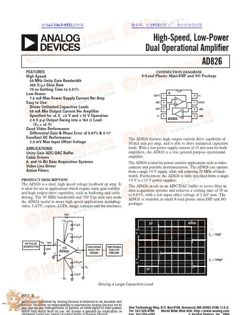
REV.BInformation furnished by Analog Devices is believed to be accurate and reliable. However, no responsibility is assumed by Analog Devices for its use, nor for any infringements of patents or other rights of third parties which may result from its use. No license is granted by implication oraAD826One Technology Way, P.O. Box 9106, Norwood, MA 02062-9106, U.S.A.Tel: 781/329-4700World Wide Web Site: High-Speed, Low-Power Dual Operational AmplifierCONNECTION DIAGRAM8-Lead Plastic Mini-DIP and SO Package12348765AD826V+OUT2–IN2+IN2OUT1–IN1+IN1V–The AD826 features high output current drive capability of 50mA min per amp, and is able to drive unlimited capacitive loads. With a low power supply current of 15 mA max for both amplifiers, the AD826 is a true general purpose operational amplifier.The AD826 is ideal for power sensitive applications such as video cameras and portable instrumentation. The AD826 can operate from a single +5 V supply, while still achieving 25 MHz of band-width. Furthermore the AD826 is fully specified from a single +5 V to ±15 V power supplies.The AD826 excels as an ADC/DAC buffer or active filter in data acquisition systems and achieves a settling time of 70 ns to 0.01%, with a low input offset voltage of 2 mV max. The AD826 is available in small 8-lead plastic mini-DIP and SO packages.10901000%500ns5V5VC L = 100pFC L = 1000pFFEATURES High Speed:50 MHz Unity Gain Bandwidth 350 V/s Slew Rate70 ns Settling Time to 0.01%Low Power:7.5 mA Max Power Supply Current Per Amp Easy to Use:Drives Unlimited Capacitive Loads50 mA Min Output Current Per AmplifierSpecified for +5 V, ؎5 V and ؎15 V Operation 2.0 V p-p Output Swing into a 150 ⍀ Load (V S = +5 V)Good Video PerformanceDifferential Gain & Phase Error of 0.07% & 0.11؇Excellent DC Performance:2.0 mV Max Input Offset Voltage APPLICATIONSUnity Gain ADC/DAC Buffer Cable Drivers8- and 10-Bit Data Acquisition Systems Video Line Driver Active FiltersPRODUCT DESCRIPTIONThe AD826 is a dual, high speed voltage feedback op amp. It is ideal for use in applications which require unity gain stability and high output drive capability, such as buffering and cable driving. The 50 MHz bandwidth and 350 V/µs slew rate make the AD826 useful in many high speed applications including:video, CATV, copiers, LCDs, image scanners and fax machines.TEKTRONIX P6201 FET PROBE HP PULSE GENERATOR1/2AD8261k ⍀50⍀1k ⍀C LV OUTV INTEKTRONIX 7A24 FET PREAMP؉V S0.01F3.3F0.01F–V S3.3F132Driving a Large Capacitive Load查询AD826AR-REEL供应商捷多邦,专业PCB打样工厂,24小时加急出货AD826–SPECIFICATIONS(@ T A = +25؇C, unless otherwise noted)Parameter Conditions V S Min Typ Max Unit DYNAMIC PERFORMANCEUnity Gain Bandwidth±5 V3035MHz±15 V4550MHz0, +5 V2529MHz Bandwidth for 0.1 dB Flatness Gain = +1±5 V1020MHz±15 V2555MHz0, +5 V1020MHz Full Power Bandwidth1V OUT = 5 V p-pR LOAD = 500 Ω±5 V15.9MHzV OUT = 20 V p-pR LOAD = 1 kΩ±15 V 5.6MHz Slew Rate R LOAD = 1 kΩ±5 V200250V/µsGain = –1±15 V300350V/µs0, +5 V150200V/µs Settling Time to 0.1%–2.5 V to +2.5 V±5 V45ns0 V–10 V Step, A V = –1±15 V45nsto 0.01%–2.5 V to +2.5 V±5 V70ns0 V–10 V Step, A V = –1±15 V70ns NOISE/HARMONIC PERFORMANCETotal Harmonic Distortion F C = 1 MHz±15 V–78dB Input Voltage Noise f = 10 kHz±5 V, ±15 V15nV/√Hz Input Current Noise f = 10 kHz±5 V, ±15 V 1.5pA/√Hz Differential Gain Error NTSC±15 V0.070.1% (R1 = 150 Ω)Gain = +2±5 V0.120.15%0, +5 V0.15% Differential Phase Error NTSC±15 V0.110.15Degrees (R1 = 150 Ω)Gain = +2±5 V0.120.15Degrees0, +5 V0.15Degrees DC PERFORMANCEInput Offset Voltage±5 V to ±15 V0.52mVT MIN to T MAX3mV Offset Drift10µV/°C Input Bias Current±5 V, ±15 V 3.3 6.6µAT MIN10µAT MAX 4.4µA Input Offset Current±5 V, ±15 V25300nAT MIN to T MAX500nA Offset Current Drift0.3nA/°C Open-Loop Gain V OUT = ±2.5 V±5 VR LOAD = 500 Ω24V/mVT MIN to T MAX 1.5V/mVR LOAD = 150 Ω 1.53V/mVV OUT = ±10 V±15 VR LOAD = 1 kΩ 3.56V/mVT MIN to T MAX25V/mVV OUT = ±7.5 V±15 VR LOAD = 150 Ω (50 mA Output)24V/mV INPUT CHARACTERISTICSInput Resistance300kΩInput Capacitance 1.5pF Input Common-Mode Voltage Range±5 V+3.8+4.3V–2.7–3.4V±15 V+13+14.3V–12–13.4V0, +5 V+3.8+4.3V+1.2+0.9V Common-Mode Rejection Ratio V CM = ±2.5 V, T MIN–T MAX±5 V80100dBV CM = ±12 V±15 V86120dBT MIN to T MAX±15 V80100dBAD826 ABSOLUTE MAXIMUM RATINGS1Supply Voltage . . . . . . . . . . . . . . . . . . . . . . . . . . . . . . .±18 VInternal Power Dissipation2Plastic (N) . . . . . . . . . . . . . . . . . . . . . See Derating CurvesSmall Outline (R) . . . . . . . . . . . . . . . . See Derating CurvesInput Voltage (Common Mode) . . . . . . . . . . . . . . . . . . .±V SDifferential Input Voltage . . . . . . . . . . . . . . . . . . . . . . .±6 VOutput Short Circuit Duration . . . . . . . See Derating Curves Storage Temperature Range (N, R) . . . . . . . –65°C to +125°C Operating Temperature Range . . . . . . . . . . –40°C to +85°C Lead Temperature Range (Soldering 10 seconds) . . . +300°C NOTES1Stresses above those listed under Absolute Maximum Ratings may cause perma-nent damage to the device. This is a stress rating only; functional operation of the device at these or any other conditions above those indicated in the operational section of this specification is not implied. Exposure to absolute maximum rating conditions for extended periods may affect device reliability .2Specification is for device in free air: 8-lead plastic package, θJA= 100°C/watt; 8-lead SOIC package, θJA = 155°C/watt.ORDERING GUIDETemperature Package Package Model Range Description Option AD826AN–40°C to +85°C8-Lead Plastic DIP N-8AD826AR–40°C to +85°C8-Lead Plastic SOIC SO-8 AD826AR-REEL7–40°C to +85°C7” Tape & Reel SOIC SO-8Parameter Conditions V S Min Typ Max Unit OUTPUT CHARACTERISTICSOutput Voltage Swing R LOAD = 500 Ω±5 V 3.3 3.8±VR LOAD = 150 Ω±5 V 3.2 3.6±VR LOAD = 1 kΩ±15 V13.313.7±VR LOAD = 500 Ω±15 V12.813.4±VR LOAD = 500 Ω0, +5 V+1.5,+3.5V Output Current±15 V50mA±5 V50mA0, +5 V30mA Short-Circuit Current±15 V90mA Output Resistance Open Loop8ΩMATCHING CHARACTERISTICSDynamicCrosstalk f = 5 MHz±15 V–80dB Gain Flatness Match G = +1, f = 40 MHz±15 V0.2dB Slew Rate Match G = –1±15 V10V/µs DCInput Offset Voltage Match T MIN–T MAX±5 V to ±15 V0.52mV Input Bias Current Match T MIN–T MAX±5 V to ±15 V0.060.8µA Open-Loop Gain Match V O = ±10 V, R LOAD = 1 kΩ,T MIN–T MAX±15 V0.150.01mV/V Common-Mode Rejection Ratio Match V CM = ±12 V, T MIN–T MAX±15 V80100dB Power Supply Rejection Ratio Match±5 V to ±15 V, T MIN–T MAX80100dB POWER SUPPLYOperating Range Dual Supply±2.5±18VSingle Supply+5+36V Quiescent Current/Amplifier±5 V 6.67.5mAT MIN to T MAX±5 V7.5mA±15 V7.5mAT MIN to T MAX±15 V 6.87.5mA Power Supply Rejection Ratio V S = ±5 V to ±15 V, T MIN to T MAX7586dB NOTES1Full power bandwidth = slew rate/2π VPEAK. Specifications subject to change without notice.ESD SUSCEPTIBILITYESD (electrostatic discharge) sensitive device. Electrostatic charges as high as 4000 volts, which readily accumulate on the human body and on test equipment, can discharge without detection. Although the AD826 features proprietary ESD protection cir-cuitry, permanent damage may still occur on these devicesif they are subjected to high energy electrostatic discharges. Therefore, proper ESD precautions are recommended to avoid any performance degradation or loss of functionality.2.0–50901.50.5–301.050703010–1080–40406020–20AMBIENT TEMPERATURE –؇CMAXIMUMPOWERDISSIPATION–WattsMaximum Power Dissipation vs. Temperature for Different Package TypesAD8262000201555101015I N P U T C O M M O N -M O D E R A N G E – ؎V o l t sSUPPLY VOLTAGE – ؎Volts–V CM+V CMFigure mon-Mode Voltage Range vs. Supply2000201555101015SUPPLY VOLTAGE – ؎VoltsO U T P U T V O L T A G E S W I N G – ؎V o l tsFigure 2.Output Voltage Swing vs. Supply 30010k1551001010201k25LOAD RESISTANCE – ⍀O U T P U T V O L T A G E S W I N G – V o l t s p -pFigure 3.Output Voltage Swing vs. Load Resistance7.75.70207.26.256.71015SUPPLY VOLTAGE – ؎VoltsQ U I E S C E N T S U P P L Y C U R R E N T P E R A M P – m AFigure 4.Quiescent Supply Current per Amp vs. Supply Voltage for Various TemperaturesS L E W R A T E – V /s20501510SUPPLY VOLTAGE– ؎Volts200300350400250Figure 5.Slew Rate vs. Supply Voltage10010.011k10k100M10M1M100k0.110FREQUENCY – HzC L O S ED -L O O P O U T P U T I M PE D A N C E – ⍀Figure 6.Closed-Loop Output Impedance vs. Frequency– Typical CharacteristicsAD8267114042–403–6065120806040100200–20TEMPERATURE – ؇CI N P U T B I A S C U R R E N T – AFigure 7.Input Bias Current vs. Temperature130301409050–4070–60110120100806040200–20TEMPERATURE – ؇CS H O R T C I R C U I T C U R R E N T – m AFigure 8.Short Circuit Current vs. Temperature 10020–601408040–4060100120806040200–20TEMPERATURE – ؇CP H A S E M A R G I N – D e g r e e s20804060U N I T Y G A I N B A N D W I D T H – M HzFigure 9.Unity Gain Bandwidth and Phase Margin vs. Temperature100–201G4010k201k 8060100M 10M1M 100k FREQUENCY – Hz+100+40+20+80+60P H A S E M A R G I N – D e g r e e sO P E N -L O O P G A I N – d BFigure 10.Open-Loop Gain and Phase Margin vs. Frequency411001k10k2356LOAD RESISTANCE – ⍀O P E N -L OO P G A I N – V /m V7Figure 11.Open-Loop Gain vs. Load Resistance10010100M30201k 10040506070809010M 1M 100k10k FREQUENCY – HzP S R – d BFigure 12.Power Supply Rejection vs. FrequencyAD826140601k 10M1208010k 100100k 1M FREQUENCY – HzC M R – dBFigure mon-Mode Rejection vs. Frequency 30100100k1M 100M10M 20FREQUENCY – HzO U T P U T V O L T A G E – V o l t s p -pFigure rge Signal Frequency Response 10–10160–4–820–602–20468140120100806040SETTLING TIME – ns O U T P U T S W I N G F R O M 0 T O ؎V0.01%0.1%1%1%0.01%0.1%Figure 15.Output Swing and Error vs. Settling Time –40–10010M–70–901k –80100–50–601M 100k 10k FREQUENCY – HzH A R M O N I C D I S T O R T I O N – dBFigure 16. Harmonic Distortion vs. Frequency50010M301010203401M100k 10k 1k 100FREQUENCY – HzI N P U T V O L T A G E N O I S E – nV / H zFigure 17. Input Voltage Noise Spectral Density380300–60140360320–40340100120806040200–20TEMPERATURE – ؇CS L E WR A T E – V /sFigure 18. Slew Rate vs. TemperatureAD826FREQUENCY – HzG A I N – d B50–5100k1M100M10M–1–2–3–41234Figure 19. Closed-Loop Gain vs. Frequency SUPPLY VOLTAGE – Volts0.130.070.10D I F FE R E N T IA L P H A S E – D e g r e e sD I F FE R E N T I A L G A I N – P e r c e n t0.10؎150.130.110.12؎5؎10Figure 20. Differential Gain and Phase vs. Supply Voltage –30–70–110100k100M10M1M10k–90–50–60–80–100–40FREQUENCY – HzC R O S S T A L K – d BFigure 21. Crosstalk vs. Frequency FREQUENCY – HZ50–5100k1M 100M10M –1–2–3–41234G A I N – dBFigure 22. Closed-Loop Gain vs. Frequency, Gain = –1FREQUENCY – HzG A I N – d B1.00–1.0100k1M 100M10M –0.2–0.4–0.6–0.80.20.40.60.8Figure 23. Gain Flatness Matching vs. Supply, G = +1USE GROUND PLANEPINOUT SHOWN IS FOR MINIDIP PACKAGEV R L = 150⍀ FOR ؎V S = 5V, 1k ⍀ FOR ؎V S = 15VFigure 24. Crosstalk Test CircuitAD826Figure 25. Noninverting Amplifier ConfigurationFigure 26. Noninverting Large Signal Pulse Response, R L = 1 k ΩFigure 27. Noninverting Large Signal Pulse Response,R L = 150ΩFigure 28. Noninverting Small Signal Pulse Response, R L = 1 k ΩFigure 29.Noninverting Small Signal Pulse Response, R L = 150 ΩAD826Figure 30.Inverting Amplifier ConfigurationFigure 31.Inverting Large Signal Pulse Response,R L = 1 kΩFigure 32.Inverting Large Signal Pulse Response,R L = 150ΩFigure 33.Inverting Small Signal Pulse Response,R L = 1 kΩFigure 34.Inverting Small Signal Pulse Response,R L = 150 ΩAD826THEORY OF OPERATIONThe AD826 is a low cost, wide band, high performance dual operational amplifier which can drive heavy capacitive and resistive loads. It also achieves a constant slew rate, bandwidth and settling time over its entire specified temperature range. The AD826 (Figure 35) consists of a degenerated NPN differen-tial pair driving matched PNPs in a folded-cascode gain stage. The output buffer stage employs emitter followers in a class AB amplifier which delivers the necessary current to the load while maintaining low levels of distortion.–INNULL 1NULL 8S–VSFigure 35. Simplified SchematicThe capacitor, C F, in the output stage mitigates the effect of capacitive loads. With low capacitive loads, the gain from the compensation node to the output is very close to unity. In this case, C F is bootstrapped and does not contribute to the overall compensation capacitance of the device. As the capacitive load is increased, a pole is formed with the output impedance of the output stage. This reduces the gain, and therefore, C F is incompletely bootstrapped. Effectively, some fraction of C F contributes to the overall compensation capacitance, reducing the unity gain bandwidth. As the load capacitance is further increased, the bandwidth continues to fall, maintaining the stability of the amplifier.INPUT CONSIDERATIONSAn input protection resistor (R IN in Figure 25) is required in circuits where the input to the AD826 will be subjected to transient or continuous overload voltages exceeding the ±6 V maximum differential limit. This resistor provides protection for the input transistors by limiting their maximum base current. For high performance circuits, it is recommended that a “bal-ancing” resistor be used to reduce the offset errors caused by bias current flowing through the input and feedback resistors. The balancing resistor equals the parallel combination of R IN and R F and thus provides a matched impedance at each input terminal. The offset voltage error will then be reduced by more than an order of magnitude.APPLYING THE AD826The AD826 is a breakthrough dual amp that delivers precision and speed at low cost with low power consumption. The AD826 offers excellent static and dynamic matching characteristics, combined with the ability to drive heavy resistive and capacitive loads.As with all high frequency circuits, care should be taken to main-tain overall device performance as well as their matching. The following items are presented as general design considerations. Circuit Board LayoutInput and output runs should be laid out so as to physically isolate them from remaining runs. In addition, the feedback resistor of each amplifier should be placed away from the feedback resistor of the other amplifier, since this greatly reduces inter-amp coupling.Choosing Feedback and Gain ResistorsIn order to prevent the stray capacitance present at each amplifier’s summing junction from limiting its performance, the feedback resistors should be ≤ 1 kΩ. Since the summing junction capaci-tance may cause peaking, a small capacitor (1 pF–5pF) may be paralleled with R F to neutralize this effect. Finally, sockets should be avoided, because of their tendency to increase interlead capacitance.Power Supply BypassingProper power supply decoupling is critical to preserve the integrity of high frequency signals. In carefully laid out designs, decoupling capacitors should be placed in close proximity to the supply pins, while their lead lengths should be kept to a mini-mum. These measures greatly reduce undesired inductive effects on the amplifier’s response.Though two 0.1µF capacitors will typically be effective in decoupling the supplies, several capacitors of different values can be paralleled to cover a wider frequency range.AD826؎SINGLE SUPPLY OPERATIONAn exciting feature of the AD826 is its ability to perform well in a single supply configuration (see Figure 37). The AD826 is ideally suited for applications that require low power dissipation and high output current and those which need to drive large capacitive loads, such as high speed buffering and instrumentation. Referring to Figure 36, careful consideration should be given to the proper selection of component values. The choices for this particular circuit are: (R1 + R3)ʈR2 combine with C1 to form a low frequency corner of approximately 30 Hz.OUT0.1VFigure 36. Single Supply Amplifier Configuration R3 and C2 reduce the effect of the power supply changes on the output by low-pass filtering with a corner at12πR3C2.The values for R L and C L were chosen to demonstrate the AD826’s exceptional output drive capability. In this configura-tion, the output is centered around 2.5 V. In order to eliminate the static dc current associated with this level, C3 was inserted in series with R L.Figure 37.Single Supply Pulse Response, G = +1,R L = 150Ω, C L = 200 pFPARALLEL AMPS PROVIDE 100 mA TO LOADBy taking advantage of the superior matching characteristics ofthe AD826, enhanced performance can easily be achieved byemploying the circuit in Figure 38. Here, two identical cells areparalleled to obtain even higher load driving capability than thatof a single amplifier (100 mA min guaranteed). R1 and R2 areincluded to limit current flow between amplifier outputs thatwould arise in the presence of any residual mismatch.LFigure 38.Parallel Amp ConfigurationAD826SINGLE-ENDED TO DIFFERENTIAL LINE DRIVEROutstanding CMRR (> 80 dB @ 5 MHz), high bandwidth, wide supply voltage range, and the ability to drive heavy loads, make the AD826 an ideal choice for many line driving applications.In this application, the AD830 high speed video difference amp serves as the differential line receiver on the end of a back terminated, 50 ft., twisted-pair transmission line (see Figure 40).The overall system is configured in a gain of +1 and has a –3 dB bandwidth of 14 MHz. Figure 39 is the pulse response with a 2 V p-p, 1 MHz signal input.Figure 39.Pulse ResponseFigure 40.Differential Line DriverLOW DISTORTION LINE DRIVERThe AD826 can quickly be turned into a powerful, low distor-tion line driver (see Figure 41). In this arrangement the AD826can comfortably drive a 75Ω back-terminated cable, with a 5MHz, 2 V p-p input; all of this while achieving the harmonic distortion performance outlined in the following table.Configuration 2nd Harmonic 1.No Load –78.5 dBm 2.150 Ω R L Only –63.8 dBm 3.150Ω R L 7.5Ω R C–70.4 dBmIn this application one half of the AD826 operates at a gain of 2.1 and supplies the current to the load, while the other pro-vides the overall system gain of 2. This is important for two reasons: the first is to keep the bandwidth of both amplifiers the same, and the second is to preserve the AD826’s ability to oper-ate from low supply voltages. R C varies with the load and must be chosen to satisfy the following equation:R C = MR Lwhere M is defined by [(M+ 1) G S = G D ] and G D = Driver ’s Gain,Figure 41.Low Distortion AmplifierAD826HIGH PERFORMANCE ADC BUFFERFigure 42 is a schematic of a 12-bit high speed analog-to-digital converter. The AD826 dual op amp takes a single ended input and drives the AD872 A/D converter differentially, thus reduc-ing 2nd harmonic distortion. Figure 43 is a FFT of a 1MHz input, sampled at 10 MHz with a THD of –78 dB. The AD826can be used to amplify low level signals so that the entire range of the converter is used. The ability of the AD826 to perform on a ±5 volt supply or even with a single 5 volts combined with its rapid settling time and ability to deliver high current to compli-cated loads make it a very good flash A/D converter buffer as well as a very useful general purpose building block.V Figure 42.A Differential Input Buffer for High Bandwidth ADCsFigure 43.FFT, Buffered A/D ConverterAD826OUTLINE DIMENSIONSDimensions shown in inches and (mm).8-Lead Plastic Mini-DIP (N) Package8-Lead SO (R) Package45؇All brand or product names mentioned are trademarks or registered trademarks of their respective holders.C 1807a –0–6/00 (r e v . B ) 00877P R I N T ED I N U .S .A .。
gjb151b-2013
南京信息工程大学电磁兼容实验室:南京信息工程大学电磁兼容实验室依托“江苏省传感网与现代气象装备”优势学科,‘江苏省信息与通信工程’优势学科,“江苏省气象探测与信号处理重点实验室”,“江苏省气象传感网技术工程中心”。
设计频率范围:10 kHz-18GHz;具有国军标151B-2013的大部分项目测试能力,实验室设备的测量结果具有高精度、高可信度和可溯源的特点,目前成功通过了中国合格评定国家认可委员会(CNAS)和国家认证认可监督管理委员会(CMA)现场评审,初步具备了国家级检测资质。
南京信息工程大学电子与信息工程学院电磁兼容实验室依托“江苏省传感网与现代气象装备”优势学科,‘江苏省信息与通信工程’优势学科,“江苏省气象探测与信号处理重点实验室”,“江苏省气象传感网技术工程中心”,成立于2012年10月。
电磁兼容暗室设计频率范围:10 kHz-18GHz;暗室经过203所验收合格。
可以满足国军标151A/151B-2013军标9项测试标准,汽车电子5项测试,具体测试项目如下:GJB151B测试项目:25Hz~10kHz电源线传导发射CE10110kHz~10MHz电源线传导发射CE10225Hz~100kHz磁场辐射发射RE10110kHz~18GHz电场辐射发射RE10225Hz~50kHz电源线传导敏感度CS10110kHz~400MHz电缆束注入传导敏感度CS11425Hz~100kHz磁场辐射发射敏感度RS10110kHz~18GHz电场辐射敏感度RS103汽车电子电磁兼容测试项目:车载零部件电源线传导发射测量\车载零部件信号\控制线传导发射测量\车载零部件大电流注入试验测量\射频电磁场辐射抗扰度静电放电抗扰度试验全部仪器都是来自安捷伦、BONN等美国、德国顶尖仪器设备,仪器设备超过5000万元。
另外学院还建有微波暗室,尺寸17×8×8大型紧缩场,测试仪器可工作到110GHz,静区2m,转台承重200kg,可满足大尺寸天线测试。
ME6211系列-C10.0
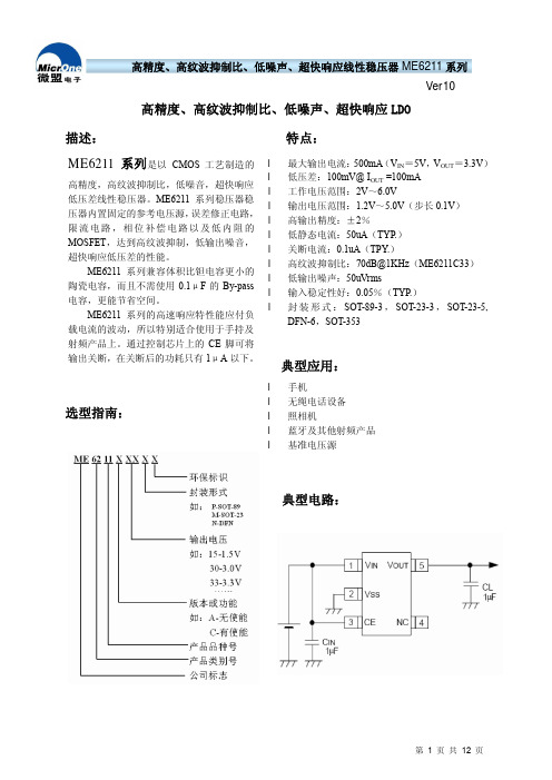
AC
IOUT=200mA,10kHZ
典型值 VOUT (T) (Note 1)
300 8 280 500 40 0.1
0.03
50 70 60 60
最大值 X 1.02
0.7
单位
V
mA mV mV mV μA μA
%/V
V V uVrms
dB
第 3 页 共 12 页
高精度、高纹波抑制比、低噪声、超快响应线性稳压器 ME6211 系列 Ver10
X 0.98
CE 端“高”电平 CE 端“低”电平
输出噪声
纹波抑制比
短路电流
VCEH VCEL EN
PSRR
ISHORT
Start up
1.0
Shut down
IOUT =40mA,300Hz~50kHz
VIN = [VOUT IOUT=10mA,1kHZ
+1]V+1Vp-p IOUT=100mA,10kHZ
DFN-6,SOT-353
典型应用:
选型指南:
l 手机 l 无绳电话设备 l 照相机 l 蓝牙及其他射频产品 l 基准电压源
典型电路:
第 1 页 共 12 页
高精度、高纹波抑制比、低噪声、超快响应线性稳压器 ME6211 系列 Ver10
引脚排列图:
引脚分配:
ME6211AXX
引脚号
SOT-23-3
IOUTMAX
∆VOUT VDIF1 VDIF2
ISS ∆VOUT ∆VIN • VOUT
IOUT=30mA, VIN= VOUT+1V VIN= VOUT+1V
VIN= VOUT+1V , 1mA≤IOUT≤100mA IOUT =100mA IOUT =200mA VIN= VOUT+1V
- 1、下载文档前请自行甄别文档内容的完整性,平台不提供额外的编辑、内容补充、找答案等附加服务。
- 2、"仅部分预览"的文档,不可在线预览部分如存在完整性等问题,可反馈申请退款(可完整预览的文档不适用该条件!)。
- 3、如文档侵犯您的权益,请联系客服反馈,我们会尽快为您处理(人工客服工作时间:9:00-18:30)。
定时器
定时器
软件、中断
2
外触发
定时器(外触发有效后)
软件、中断
3
BURST(突发)
外触发输入
软件、中断
▲
功能: 送8位数字量输出.
D0-D7对应输出0-输出7
▲
功能: 读8位数字量输入.
D0-D7对应输入0-输入7
例:输出DATA=55H,将数据读入DATA
outp(0x213,0x55);
data=inp(0x213);
§5. AC1077软件及MS C 程序库说明
§
在AC1077板应用前, 请仔细检查AC1077板的开关设置是在您需要的位置, 共有2个开关: S1, S2 (位置见书后附录)。当跳线器设置完毕后,关掉PC电源,将AC1077插入PC机,并将外部连线接好。
注意:
AC1077的附带测试软件要求:
1.AC1077的地址设置为:210H
}while(i!=0);
▲
功能:对AC1077的A/D进行校正操作。
CAL操作通常注意在PC及上电后进行一次即可以。如果长时间工作,温度变化的比较大,可以对A/D每隔一定时间进行一次CAL操作。一次CAL操作的时间为:20毫秒左右。方法对1H口进行一次读操作,然后判断STATE(0H读)的D0位是否为“0”。
6.所有输入电压应该小于±15V,否则可能损坏输入开关。
7.PC机上电后应该至少进行一次CAL-校正操作。
模拟输入连接:
单端方式:
主要应用在前端输出为共地信号及输出与PCΒιβλιοθήκη 离不远(小于2米)的条件下。连接如下:
差分模式:
主要应用在前端为差分输出及远距离信号传输。
建立时间
AC1077的输入建立时间为20微秒,即如果应用在多通道采样时,从一个通道转换到另一个通道需要有20微秒以上的通道稳定时间,然后在进行采样。在应用中,用户可以应用二次A/D转换来代替20微秒的通道稳定时间(一次转换大约需要12微秒的时间)。
▲
功能:
1)读转换结果,操作为16位读操作
2)定时器模式时(MODE=1,2,3),清除状态标志,(STATE=1)
读结果位DATA,二进制补码(同PC语言的定义),对应电压:
数据 DATA
电压 V(V)
32767 7FFFH
10V
0 0H
0V
32768 8000H
-10V
65535 FFFFH
-0.00031V
AC1077
高精度50KHZ 16位A/D板
□程控16路单端或8路差分输入,输入±10V
□16位A/D,50KHz通过率
□工作方式:
软件启动,定时器启动、外触发启动、
BURST模式
软件查询、中断
□8入/8出数字I/O
□MS C语言应用程序库
wwlab
2001年5月
AC1077
AC1077具有高分辨率、高精度及采样速度高的特点。通道输入采用可编程单端或差分模式,可以使用户单端与差分模式混合应用以节省输入通道的数量。AC1077的模拟部分采用高质量芯片及多种噪音处理方式,具有很高的高稳定度及分辨率,是一款强调模拟性能的模板。
4.关好PC机的机箱
5.完毕
注意事项:
1.应该选用质量好的PC机及电源系统以减少对AC1077的干扰
2.模拟输入连线必须采用屏蔽电缆
3.不用的模拟输入通道最好接地
4.外触发输入应连接外部的开关量输出,输入电压:0-5V,不容许应用模拟输入电压。外触发信号位由0-5V的正上升边沿有效。
5.差分输入时,应该连接输入的保护地线,即:将前端的输出部分的地线与AC1077的模拟地连接在一起。并注意输入共模电压(同时加在+与-输入上的干扰电压小于15V)。
D4:模式选择,D4=0:单端输入模式,D4=1:差分输入模式。
例: 选择通道"1", 为单端输入模式,选择差分输入通道“0”(占用单端输入的通道0及8号)则:
CH1 = 1H
CH2=10H+0=10H
操作: outp(0X210,CH1) ;
outp(0x210,CH2);
* 以下程序例皆为: MS C6.0 C7.0 或 MS QC2.5 语句.
MS C i=inp(adr) outp(adr,data) i=inpw(adr)
BC i=inport(adr) outp(adr,data)i=inportw(adr)
汇编I in al,dx out dx,alin ax,dx
adr:操作地址 data:数据 i: 变量
详细操作说明:
▲
功能: 送A/D通道号及模拟模式选择
S1
1
2
3
4
5
6
0
1
1
1
1
0
A4
A5
A6
A7
A8
A9
“0”表示跳线器空
“1”表示跳线器被短路
上面的设置位选择SEG=210H,即AC1077的缺省设置地址。
注意:PC常用的地址为:
210H,220H,230H,240H,290H,2A0H,2B0H,2C0H,2D0H,2E0H,300H,310H,320H,330H
例:
int i;
// 启动CAL操作
i=inp(0x211);
//判断CAL操作是否结束
do{
i=inp(0x210) & 1;
}while(i!=0);
▲
功能:
1.软件启动模式:启动A/D转换
2.定时器方式:启动定时器控制的A/D转换
3.外触发启动:启动模式,等待外触发输入。
4.BURST模式:启动BURST模式,有触发输入时,开始转换
BURST(突发)模式(A/D每次转换由外触发输入控
制,每一次外触发启动一次A/D转换)
- 外触发电平: TTL电平,低电平:0-0.6V,高电平:
2.5V-5V,上升边沿有效,输入电流:
0.4mA,充分延时:小于1微秒。
- 板上定时器:
定时器输入基准4MHz时钟(0.25uS周期)
分辨率:16位,定时范围:12 uS - 16mS.
D7 D6 D5 D4 D3 D2 D1 D0
模式选择 D0-D3:通道选择
D0-D3: =0-15选择输入通道,单端模式时对应通道0-15
差分模式:D0-D3=0-7,对应差分输入通道0-7
注意:AC1077容许差分与单端模式混合应用,但被单端或差分输入占用的通道不能为其它的模拟输入模式应用。差分模式占用二个模拟输入对应输入的+及-,因此差分模式只有8个输入-对应D0-D3=0-7,但单端模式有16个输入通道对应D0-D3=0-15。
2.中断设置为:IRQ10
跳线器功能与设置:
S1:6位跳线器-地址设置开关。
S2:3位跳线器,中断选择。
一
地址:S1
AC1077板上占用4条地址线A0-A3, 称为"基地址" base, 余下的6条I/O译码地址(A4-A9), 称为"段地址" seg , 由S1 六位跳线器开关选择, 其1-6号位置对应选择地址A4-A9,地址按二进制方式排列。定义如下:
AC1077.C
- AC1077的 MS C6.0 C7.0 或 MS QC2.5 应用库代码
LIB1077.C
AC1077
目录
AC1077简介
§1. AC1077性能
§2. AC1077跳线器及功能说明
§3. AC1077编程及硬件
. A/D接口.
. 数字I/O
§4. AC1077电缆接口说明.
. AC1077各电缆联接器及地址选择跳线器位置
outp(0x211,0);
▲
功能:
1)设定A/D工作模式, 及PC中断容许
2)工作在定时器及外触发模式时,设置模式为“0”,中断原来的操作。
D7 =1容许中断7,=0: 禁止中断
D6
D5
D4
D3
D2
D1 ━┓
D0 ━┛工作模式: M = 0 - 2
M
模式
A/D 启动方式
采样结束判断方式
0
查询
软件
软件
1H
CAL:启动CAL-A/D的自校正操作
RUN:启动转换
2H
MODE:工作模式寄存器
3H
DI:开关量读操作
DO:开关量写操作
4H
ADDATA:读A/D转换结果
*16位读操作
CH
D8253:定时器8253的数据寄存器
FH
T8253:定时器设置寄存器
常用PC语言的I/O操作指令:
语言 读操作 写操作16位读操作
- 温度系数:小于10ppm/度
- 输入共模抑制比:大于80dB
- 输入阻抗:(JFET输入放大器),大于100M欧姆
- 采样保持器参数:
最小采样时间:2微秒
孔径延时:6nS
孔径抖动:100pS
● 采样控制部分:
- A/D转换结束判断方式: 查询, 中断
- A/D起动方式: 软件起动, 定时器启动, 外触发启动,
* DATA=D15 - D0 为: 对应一次读入的16BIT A/D 结果
* A/D输出在双极性状态时, 输出为补码: (设输入为: 0 - ±10V)
表示为:
DATA <= 7FFFH (32767) :
输入电压 V = (N * 10000.0) / 32768.0 (mV)
DATA > 7FFFH (32767) :
V = (N - FFFFH) * 10000.0 / 32768.0 (mV)
* 输出数据正好等效为 MS C 语言的 INT 类型整数的定义
