麦当劳常用财务概念及计算公式-OI;McOpCo_Margin%;Cash_Flow;CM%
广义凸函数

广义凸函数一、引言1.1 定义广义凸函数是凸函数的推广形式,是一类在函数分析和优化理论中经常出现的函数。
广义凸函数在实际问题建模和解决中有着重要的应用价值。
本文将对广义凸函数进行全面深入的讨论,包括定义、性质、判别准则以及应用等方面。
1.2 凸函数回顾在介绍广义凸函数之前,我们先回顾一下凸函数的定义。
若对于定义域上的任意两点x和y,以及实数λ∈[0,1],满足以下性质:f(λx+(1−λ)y)≤λf(x)+(1−λ)f(y)其中0≤λ≤1,则函数f(x)在定义域上为凸函数。
二、广义凸函数的定义2.1 函数定义广义凸函数通过引入一个额外的点列来扩展凸函数的定义。
如果对于定义域上的所有点,以及非空的点列{x1,x2,…,x k}以及非负权重系数λ1,λ2,…,λk,满足以下性质:f(∑λiki=1x i)≤∑λiki=1f(x i), λi≥0, ∑λiki=1=1则函数f(x)在定义域上为广义凸函数。
2.2 例子举例来说,若f(x)在定义域上连续且具有二阶连续导数,则f(x)为凸函数当且仅当其二阶导数非负。
而对于广义凸函数,若f(x)在定义域上具有k阶连续导数,则f(x)为广义凸函数当且仅当其k阶导数非负。
三、广义凸函数的性质广义凸函数具有一些重要的性质,这些性质可以帮助我们更好地理解和应用广义凸函数。
3.1 Jensen 不等式Jensen 不等式是广义凸函数的重要性质之一。
对于定义域上的广义凸函数f (x ),以及非空的点集{x 1,x 2,…,x k }以及非负权重系数λ1,λ2,…,λk ,满足∑λi k i=1=1,Jensen 不等式表示:f (∑λi k i=1x i )≤∑λi ki=1f (x i )其中等号成立当且仅当x 1=x 2=⋯=x k 时。
3.2 Hessian 矩阵对于广义凸函数,我们可以使用Hessian 矩阵来判定其凸性。
若定义域上的函数f (x )的Hessian 矩阵半正定,则f (x )为广义凸函数。
Qtum量子链CodeFace带你分析ICO众筹合约代码
ICO众筹合约代码分析ICO是以初始产生的数字加密货币作为投资回报的一种筹措资金的方式,它的概念源自证券界的Initial Public Offering(IPO,首次公开发行)。
相较于传统意义上的IPO,ICO具有可以缩短投融资链、降低投融资门槛、流动性佳、全球性投资等优势。
它可以让项目在最开始阶段就面对投资者,极大降低投融资双方的投资门槛,基于数字货币特性,ICO可以汇集全球投资者的资金。
本文将对过往知名的ICO项目合约代码进行分析,方便大家参考学习。
AugurAugur 是建立在以太坊平台上的去中心化预测市场平台,也是以太坊平台上第一个众筹的应用,利用Augur任何人都可以为任何自己感兴趣的主题创建一个预测市场,并提供初始流动性。
Augur 项目于2015年8月开启代币众筹,一共众筹到500万美元,代币名称为REP。
Augur众筹既支持比特币也支持以太,众筹合约和Token交易合约是分为两个部分,众筹完成后再根据众筹时的以太坊地址分配Token。
众筹合约源代码地址:https:///AugurProject/token-saleToken交易源代码:https:///AugurProject/augur-core/blob/develop/src/repContract.seAugur众筹时的solidity语法和现在相比有了很多变化。
// Funders保存了众筹时的每一笔参与情况,amount记录以太数量、blockN um记录区块高度、address记录发送者地址。
data Funders[](address, amount, blockNum)// Funders数组长度data funderNum// addrToFunderNum记录了每个账号的记录IDdata addrToFunderNum[]// augur团队的以太坊账号地址data augurAddress// 众筹截止时间data deadlinedef init():self.augurAddress = 0xa04fc9bd2be8bcc6875d9ebb964e8f858b cc1b4fself.deadline = 432015// 参与众筹调用的函数def buyRep():if(msg.value==0): return(0) if(block.numbe r < self.deadline):// 将以太发送到augur团队的以太坊账号上send(self.augurAddress, msg.value)// 记录每一笔众筹转账记录self.Funders[self.funderNum].amount = msg.valueself.Funders[self.funderNum].blockNum = block.num berself.Funders[self.funderNum].address = tx.origin// 记录该用户的记录IDself.addrToFunderNum[tx.origin] = self.funderNumself.funderNum += 1return(1) else: return(0)// 还有其他函数不展示了。
SOLIDWORKS Composer 3D 技术文档说明书

OBIETTIVISOLIDWORKS® Composer è uno strumento 3D che consente di riutilizzare i dati tecnici 3D per creare contenuti grafici in grado di spiegare processi e procedure all'interno delle comunicazioni tecniche. Questi contenuti includono istruzioni di assemblaggio per la produzione, manuali dei prodotti, istruzioni di installazione, manuali di assistenza, manuali per la formazione, brochure di marketing e offerte per le vendite.PANORAMICASOLIDWORKS Composer è uno strumento per la crea-zione di supporti per la comunicazione, quali istruzioni di assemblaggio, elenchi di parti e supporti di presen-tazione, che possono essere costituiti da pagine HTML interattive, animazioni, immagini rasterizzate o grafica vettoriale. I dati di SOLIDWORKS o di altre applicazioni CAD possono essere importati in SOLIDWORKS Composer e organizzati in viste costituite da istantanee dei dati dell'assieme con orientamenti e stati diversi, in cui le parti vengono mostrate e nascoste in base alle esigenze. Poiché SOLIDWORKS Composer è un software associa-tivo, è possibile aggiornare automaticamente i materiali di comunicazione tecnica con le modifiche apportate ai modelli CAD. Per la prima volta, potrete ridurre i tempi di realizzazione dei prodotti con la garanzia di avere sempre una documentazione accurata e di alta qualità. Gli ele-menti grafici e le animazioni di SOLIDWORKS Composer sono particolarmente utili nella semplificazione delle istruzioni di assemblaggio e degli ordini di lavoro. Potete visualizzare direttamente in 3D le modalità di assemblag-gio o riparazione del prodotto, riducendo la probabilità di errori in officina, eliminando le barriere linguistiche e riducendo notevolmente i costi di localizzazione. VANTAGGIRiduzione dei ritardi nel time-to-market. SOLIDWORKS Composer consente di ridurre gli errori nella documenta-zione e garantire la commercializzazione di tutti i materiali più rapidamente grazie ai seguenti vantaggi:• Creazione anticipata della documentazione durante il processo di progettazione e aggiornamenti più rapidi in caso di modifiche al progetto.• Creazione di contenuti 3D interattivi che chiunque potrà visualizzare con il software gratuito SOLIDWORKS Composer Player.• Aggiunta di elementi grafici interattivi ai materialidi formazione.• Creazione di rendering ombreggiati ad alta risoluzione e con effetti 3D per presentazioni e brochure.• Pubblicazione rapida online di dettagli dei prodotti complessi tramite modelli Web.Maggiore soddisfazione dei clienti. Una grafica di prodotto azzeccata può fare la differenza fra raggiungere l'obiettivo di vendita prefissato o mancarlo. Con SOLIDWORKS Composer è possibile:• Creare immagini più realistiche, eliminando la necessità di prototipi fisici durante la realizzazione dei materiali di marketing per il prodotto.• Illustrare in modo efficace i prodotti constoryboard interattive.• Evidenziare i principali elementi distintivi chiave con viste dettagliate, effetti di luce e componenti trasparenti.• Stupire i prospect visualizzando velocemente gli aggiornamenti dei progetti.• Creare animazioni interattive per rappresentare in modo efficace i dettagli più complessi del prodotto. Maggiore chiarezza nelle comunicazioni. Non è più necessario scendere a compromessi nella comunicazione, acconten-tandosi di disegni poco dettagliati per illustrare il concept o aspettando la fine del progetto per iniziare a creare i materiali di comunicazione del prodotto. Con SOLIDWORKS Composer, sarà possibile creare in maniera semplice:• Viste dettagliate• Viste esplose• Immagini ad alta risoluzione• Illustrazioni tecniche• Animazioni interattive• Distinte di materiali ed elenchi di parti interattivi3D EXPERIENCE platform migliora le applicazioni del marchio al servizio di 12 settori industriali ed offre un'ampia gamma di esperienze di soluzioni industriali.Dassault Systèmes, the 3D EXPERIENCE ® Company, mette a disposizione di aziende e persone universi virtuali in cui immaginare innovazioni per un mondo sostenibile. Le sue soluzioni leader a livello mondiale trasformano il modo in cui i prodotti vengono progettati, realizzati e gestiti. Le soluzioni collaborative di Dassault Systèmes promuovono l'innovazione sociale, aumentando le possibilità che il mondo virtuale migliori il mondo reale. Il gruppo offre valore a oltre 220.000 aziende di tutte le dimensioni e di tutti i settori industriali in oltre 140 Paesi. Per ulteriori informazioni, visitare il sito web /it .AmericheDassault Systèmes 175 Wyman Street Waltham, MA 02451 USAEuropa/Medio Oriente/Africa Dassault Systèmes10, rue Marcel Dassault CS 4050178946 Vélizy-Villacoublay Cedex FranciaDassault Systèmes Italia s.r.l.+39-049-8176400 ************************©2018 D a s s a u l t S y s t èm e s . T u t t i i d i r i t t i r i s e r v a t i . 3D E X P E R I E N C E , l 'i c o n a C o m p a s s , i l l o g o 3D S , C A T I A , S O L I D W O R K S , E N O V I A , D E L M I A , S I M U L I A , G E O V I A , E X A L E A D , 3D V I A , 3D S W Y M , B I O V I A , N E T V I B E S , I F W E e 3D E X C I T E s o n o m a r c h i c o m m e r c i a l i o m a r c h i r e g i s t r a t i d i D a s s a u l t S y s t èm e s , u n a "s o c i ét é e u r o p ée n n e " f r a n c e s e (r e g i s t r o d e l c o m m e r c i o d i V e r s a i l l e s n r . B 322 306 440), o d e l l e s u e c o n s o c i a t e n e g l i S t a t i U n i t i e /o i n a l t r i P a e s i . T u t t i g l i a l t r i m a r c h i s o n o d i p r o p r i e t à d e i r i s p e t t i v i p r o p r i e t a r i . L 'u s o d e i m a r c h i d i D a s s a u l t S y s t èm e s o d e l l e s u e c o n s o c i a t e è s o g g e t t o a l l a l o r o a p p r o v a z i o n e e s p l i c i t a p e r i s c r i t t o .FUNZIONALITÀSOLIDWORKS Composer• Le istruzioni di assemblaggio contengono informazioni aggiornate derivanti dagli ordini di modifica emantengono le informazioni di progettazione, riducendo i dubbi nell'officina e le incomprensioni dovute alle barriere linguistiche.• I manuali dei prodotti, le guide all'assistenza eall'installazione hanno sempre un aspetto professionale e vengono aggiornati a ogni modifica dei prodotti. Il risultato: riduzione delle chiamate all'assistenza ed elenchi parti sempre aggiornati.• I materiali di formazione vengono sviluppati in modo intelligente, su misura per gli utenti finali a cui sono destinati, consentendo di ridurre una curva di apprendimento altrimenti elevata.• I materiali di vendita e di marketing spiccano su quelli della concorrenza e rimangono sempre aggiornati a ogni modifica dei prodotti.• Le presentazioni di revisione dei progetti vengonorealizzate in modo semplice, per ridurre le incomprensioni e ottenere maggiore consenso.SOLIDWORKS Composer PlayerPiù che un semplice visualizzatore, SOLIDWORKS Composer Player consente:• Agli utenti finali di accedere ai contenuti grazie a questa utility gratuita.• Agli utenti dell'officina, ai clienti e ai partner di osservare il funzionamento del prodotto, le possibilità che offre e il modo in cui utilizzarlo con contenuti 3D interattivi.• Ai team di produzione di visualizzare come è assemblato il prodotto.• Ai rappresentanti del servizio clienti di seguire il processo di riparazione.• Ai clienti di osservare il prodotto in azione, ancora prima che venga realizzato.SOLIDWORKS Composer Player Pro• Creazione di demo personalizzate dei prodotti, contenuti interattivi e istruzioni di assemblaggio per consentire di comprendere rapidamente qualsiasi processo.• Varie funzioni, tra cui rotazione, zoom, animazioni e misurazioni, nonché la capacità di visualizzare le distinte materiali, in un ambiente in cui i diritti sono controllati dall'autore.• Visualizzazione di istruzioni interattive dettagliate senza alcuna interfaccia utente aggiuntiva.• Creazione di applicazioni personalizzate da distribuire internamente o sul sito Web mediante API (Application Programming Interface).SOLIDWORKS Composer Sync• Aggiornamento dei metadati, della geometria, delle distinte materiali e delle informazioni di produzione.• Automazione batch per gli output, conversione batch e aggiornamento.• Presenta un grande insieme di modelli.SOLIDWORKS Enterprise Composer Sync• Personalizzazione e integrazione con sistemi PLM (Product Lifecycle Management).• Importazione automatica in modalità batch di file 3D e pubblicazione del contenuto.• Automazione della creazione dei documenti in sistemi di flusso di lavoro esistenti.• Automazione della conversione dei documenti mediante un programma XML personalizzato.SOLIDWORKS Composer Check• Utilizzo del rilevamento delle interferenze statiche e dinamiche.• Funzioni di Controllo ingombro: test delle interferenze, test della distanza minima e controllo dell'ingombro.• Rilevamento delle collisioni interattivo per individuare le collisioni durante le animazioni.• Convalida delle procedure di assistenza e assemblaggio prima della commercializzazione dei prodotti.。
SleepSafe 床垫说明书

good night.sleep safe.Your Checklist for Preparing to Order the Correct SleepSafe ® BedWhen ordering your SleepSafe® Bed, please select the following choices:1. Rail Height: O LOW O MEDIUM O TALL O BASIC (Product has limitations)2. Foundation: O FIXED with Box Spring O FIXED with Bunkie Board O ARTICULATED O HI-LOO MANUAL _Full HiLo _HiLo Only _Articulation Only _ Electric Articulation / Manual HiLo 3. Finish: O OAK O MAPLE O CHERRY O MAHOGANY O ALDERO SOLID COLOR __White __Blue __Green __Red __Yellow __Orange __Purple __Pink __BlackO MULTI COLOR (Please call for a form to select your color combination.) 4. Bed Size: O TWIN O FULL O QUEEN5. Padding: O PADDING AROUND WINDOWS O PADDING OVER WINDOWS O NO PADDINGPADDING COLOR __Cream __Gray __Light Blue __Taupe6. Windows: O CLEAR WINDOWS O MESH WINDOWS O CLEAR/MESH COMBINATION7. Extras: O HEADBOARD WINDOW O FOOTBOARD WINDOWO IV POLE KIT O TUBING CHANNEL ACCESS O DUAL VIEW (Tall Bed)O SleepSafer® EXTENSION O SleepSafer® EXTENSION with ENCLOSURE3629 Reed Creek Drive · Bassett, VA 24055 · Local: 276-627-0088 · Fax: 276-627-0234All SleepSafe® Beds include these items:• Bed Enclosure• Foundation• Premium Mattress • Casters• Assembly Instructions • Tools for Assembly• Standard Shipping Within the Continental US Made in USASafety FirstTHREE MODELS of SleepSafe ® Beds are available in TWIN, FULL and QUEEN sizes with safety rail height protection ranging from 8¾” to 36¼” above the mattress depending on the foundation. Appropriate SAFETY RAIL HEIGHT is based on the activity level of the user, with more active users requiring additional height.SleepSafe® Beds are a proven, ultra-safe solution to address problems with entrapment and falls. Unique in the industry, these beds meet or exceed FDA guidelines on the 7 Zones of Entrapment .SleepSafe® II Medium Bed with Alder finishPremium Memory Foam MattressSleepSafe® Beds use CertiPUR-US ® compliant foam products for our mattresses featuring gel technology. They provide optimized pressure redistribution, rapid heat dissipation, and increases in breathability compared to standard foam. Mattresses support up to 350 pounds. Full details are available on our website.Resists BurrowingThe SleepSafe ® precision-fi t custom mattress fi ts tightly within the bed frame. Even with aggressive compression, it is diffi cult to burrow deeply enough to create an entrapment issue or safety hazard.Clear, break-resistant windows, or our new Please consider the TRANSFER HEIGHT before ordering your bed. It is the distance from the topof the side panel (below the safety rail) to the fl oor. SleepSafe® - LOW - 18½” or 20” Transfer Height SleepSafe® II - MEDIUM - 29½” or 31” Transfer Height SleepSafer® - TALL - 23½” or 25” Transfer Height Easily MovedCasters provide mobilityand can be locked.Safest Yet!SleepSafer® Extension Kit increases bed safety height another 16¾”. The Kit, with or without top enclosure, may be included with a new bed order or can be sent as a retrofi t for most existing beds. Screen mesh windows off er additional ventilation.SleepSafer®SleepSafe® II SleepSafe®Safety Rail Heights – 3 ModelsLOW – This is our classic SleepSafe® bed with safety rails ranging up to 17¼” above the mattress depending on the foundation choice.MEDIUM – The SleepSafe® II provides protection ranging up to 27” above the mattress depending on the foundation choice.TALL – The SleepSafer® provides protection up to 36¼” above the mattress depending on the foundation choice. The SleepSafer® Extension Kit off ers an additional 16¾” of safety rail height when ordered or retrofi tted to your existing SleepSafer® Bed.50¾”57”MEDIUM TALL40¾”SleepSafe® BedSpecifi cationsLow BedSleepSafe®Medium Bed SleepSafe® IITall Bed / ExtensionSleepSafer®SAFETY RAIL HEIGHT Distance from the top of mattress to the top of the safety railFixed Foundation with Box Spring (Choice of settings)12” or 8¾” 17¾”, 14” or 10”31” or 24¾” / 47¾” or 41½” Fixed Foundation with Bunkie Board (Choice of settings)17¼” or 14” 27” or 21¾”36¼” or 30” / 53” or 46¾” Manual Articulating Foundation 15” or 11¾”21”, 17” or 13¼”34” or 27¾” / 50¾” or 44½” Manual HI-LO FoundationLO 11½” to EVEN with rail LO 21¼” to HI 9½” or LO 16” to HI 4¼”LO 30½” to HI 18¾” / LO 47½” to HI 35¾”Articulating Foundation (Choice of settings)15” or 11¾”21”, 17” or 13¼”34” or 27¾” / 50¾ or 44½”Electric HI-LO Foundation (LO to HI Settings)LO 11½” to HI 1¼” below rail LO 21¼” to HI 11” or LO 16” to HI 5¾” LO 30½” to HI 20¾” / LO 47½” to HI 37¼”MATTRESS HEIGHT Distance from the top of the mattress to the fl oor.Fixed Foundation with Box Spring (Choice of settings)23¾” or 27” 28”, 32” or 35½”23¾” or 30”Fixed Foundation with Bunkie Board (Choice of settings)18½” or 21¾”18¾” or 24”18½” or 24¾”Manual Articulating Foundation 20¾” or 24”25”, 28¾” or 32½”20¾” or 27”Manual HI-LO FoundationLO 24¼” to HI 36” LO 24½” to HI 36¼” or LO 29¾” to HI 41½”LO 24¼” to HI 36” Articulated Foundation (Choice of settings)20¾” or 24”25”, 28¾ or 32½”20¾” or 27”Electric HI-LO Foundation - (LO to HI Settings)LO 24¼” to HI 34½” LO 24½” to HI 34¾” or LO 29¾” to HI 40” LO 24¼” to HI 34½”FLOOR TO RAIL HEIGHTDistance from the top of the rail to the fl oor.35¾”45¾”54¾” / 72”OVERALL OUTSIDE DIMENSIONSTwin 42¼” W x 80½” L x 40¾”H 42¼” W x 80½” L x 50¾”H 42¼” W x 80¼” L x 56”H (72¾”H w/Ext.)Full 56” W x 80” L x 40¾”H 56” W x 80” L x 50¾”H 56” W x 80” L x 57”H (72¾”H w/Ext.)Queen65” W x 80” L x 40¾”H 65” W x 80” L x 50¾”H 65” W x 80” L x 57”H (72¾”H w/Ext.)MATTRESS SIZE Width without pads / Width with pads / LengthTwin 38” W / 36” W / 77” L 38” W / 36” W / 77” L 38” W / 36” W / 77” L Full 51” W / 50” W / 77” L 51” W / 50” W / 77” L 51” W / 50” W / 77” L Queen61” W / 60” W / 77” L 61” W / 60” W / 77” L 61” W / 60” W / 77” L UNDER BED FLOOR CLEARANCEStandard Models8”8”7¾”TRANSFER HEIGHT Distance from the topedge of the folded down safety rail to the fl oor.22¼” with Safety Rail On20¾” with Safety Rail Off32” with Safety Rail On30½” with Safety Rail Off26” with Safety Rail On24½” with Safety Rail Off72¾” w/Extension7/17HI -L O FO UN DA TI ONAll ow s c on tro l o f th e fra me he igh t a s w ell as th e h ea d a nd kn ee el ev ati on .Sle ep Sa fe® II sh ow n h ere wi th ou t th e m att res s.FoundationsFIXED – The mattress rests on a fi xed foundation, which can be a box spring or bunkie board, depending on the safety rail protection needed. A bunkie board allows 6” of addtional safety rail height.MANUAL – Off ers four NON-ELECTRIC options: Full HiLo Manual, Manual Hi-Lo only, Manual articulation only, and Electric articulation with Manual Hi-Lo. Cranks are located in front, below the safety rail.ARTICULATED – The mattress rests on an ELECTRIC frame that has both head and knee articulation, operated by a handheld remote. HI-LO – The mattress rests on an ELECTRIC frame that off ers mattress height adjustability as well as head and knee articulation. The surface of the mattress can be adjusted from 22¾” to 38¾” from the floor.AccessoriesDUAL VIEW SAFETY RAILS For more visibility or accessibility, our SleepSafer® TALL bed may be ordered with see-through rails on both sides.SLEEPSAFER® EXTENSION KIT increases bed safety height another 16¾”. The kit, with or without top enclosure, may be included with a new bed order or can be sent as a retrofi t for most existing beds.PADDINGCustom-fi t padding provides protection from contact with the bed frame. The 3/4” high-density foam is covered with easy to clean waterproof nylon. Pads can be ordered to surround the windows or cover the windows. They can be removed for cleaning. IMPORTANT: When required, padding needs to be indicated at the time of ordering your bed. IV ATTACHMENT KIT A stainless steel IV pole, along with an access area, may be orderedwith your bed.SleepSafe II Medium Bedwith Alder FinishBreak-resistant windows are availablefor the headboard and/or footboard.Finish ChoicesSleepSafe® Beds can be fi nished using one of these choices:SOLID COLORSBright, highly durable surfaces off er a suitable option for matching any decor. Colors: White, Blue, Green, Red, Yellow,Orange, Purple, Pink and Black.OAKMAPLECHERRYMULTICOLOR MIX & MATCHYou can mix and match the colors for a truly unique bed. Please call for details!SleepSafe II Medium Bed with Oak FinishMAHOGANYALDER12 34FDA RegisteredSleepSafe® II - Medium Bed Full Size - CherryThe New SleepSafe ® Manual Safety Bed.RETHINKING THE WAY SAFETY BEDS CAN WORK.Manual Foundation no w offers four choices with easy to operate hand cranks.UP FRONT CONTROL AND VERSATILITY.CONTROLS KNEE ELEVATION1) Manual Hi-Lo - Hi-Lo Foundation with Articulation.This will raise and lower the mattress height and raise and lower the head and knee section of the bed by using the three cranks.2) Manual Flat - Hi-Lo Foundation without Articulation.This will raise and lower the mattress height by using one crank located in the center of the front panel of the bed.3) Manual Electric - Articulating Foundation with Manual Hi-Lo. This will raise and lower the head and/or knee section of the bed electrically with remote. Will raise and lower mattress manually.4) Manual Plus - Articulating Foundation without Hi-Lo.This will raise and lower the head and/or knee section of the bed by using two cranks located in the front panel of the bed.SleepSafe® Beds is a domestic USA manufacturer of custom safety beds, featuring removable safety side rails, designed to address the issues of falls and entrapment for those with special needs. Models include SleepSafe®-Low Bed, SleepSafe® II- Medium Bed, and SleepSafer®- Tall Bed , offering progressively more safety rail to mattress height.SleepSafe® Beds are built to order, offering twin, full or queen size; fixed, articulating or HiLo foundations; padding; wood and color choices, and other helpful options. SleepSafe® Beds help those with special needs get a safe, restful sleep with peace of mind for their caregivers.CONTROLS HEAD ELEVATIONCONTROLS MATTRESS HEIGHTFDA RegisteredWe’re here to help.SleepSafe® Beds is a domestic USA manufacturer of custom safety beds, featuring removable safety side rails, designed to address the issues of falls and entrapment for those with special needs. Models include SleepSafe®-Low Bed, SleepSafe® II- Medium Bed, and SleepSafer®- Tall Bed, offering progressively more safety rail to mattress height.SleepSafe® Beds are built to order, offering twin, full or queen size; fixed, articulating or HiLo foundations; padding; various finishes, and other helpful options.SleepSafe® Beds help those with special needs get a safe, restful sleep with peace of mind for their caregivers.SleepSafe II® - Medium Bed - Alder - Both Safety Rails Up- Manual Crank for HiLo control of mattress height - 31.5” Transfer HeightSleepSafe II® - Medium Bed - Multi-Color (Customer’s Choice)- Both Safety Rails Up - 31.5” Transfer HeightSleepSafer®- Tall Bed - Cherry - Shows Extension and Top- Extension Adds 16.75” to Safety Rail Height - Shows optional screened mesh windows - Extension may be ordered with or without Top.- Safety Rail Flip Open Option is Available - 25.5” Transfer HeightSleepSafe® - BASIC Bed - Maple - One Safety Rail Up, One Down - Bunkie Board Fixed Foundation - 21.25” Transfer HeightSleepSafe® - Low Bed - Oak - One Safety Rail Up, One Down- Manual Crank for Head and Knee Articulation - Screened Mesh WindowsSleepSafe II® - Medium Bed - Oak - Padding surrounding clear windows - IV Pole with Medical Tubing Access - One Safety Rail Up, One Down - 31.5” Transfer Height。
ZedGraph源码学习(一)

ZedGraph源码学习(⼀)因⼯作原因,学习相关ZedGraph源码来解决⼀些问题。
刚看到这个开源图表控件时,感觉还是短⼩精悍的。
结合ZedGraph控件的例⼦⼤致看了下对应的源码,写下点感悟。
这⾥先⼤致说⼀些ZedGraph⾥的元素。
1.Panel:ZedGraph控件是如何画出来的,就是这这个上⾯画出来,后⾯的元素如坐标轴,线条,饼图。
2.Axis:轴线,任何⼆维线型、条型、饼型图表都需要⼀个坐标轴,⾄少有X轴,Y轴,然后我们才能在上⾯画相应的线条,饼型等元素。
3.CurveItem:我们刚说到在有坐标轴后,那么需要画我们的线条,条型,饼型什么的,CurveItem就是存储我们的数据然后画出对应的图形。
4.GraphObj:我们在整个Panel⾥可能要标出⼀些信息,如某点要添加相应描述,或是我们要标⽰有⼀部分是警告区域,都可以由这个来完成。
5.MajorTic与MinorTic:这⼆个对象都是针对Axis来说的,主要是描述上⾯的轴线上的主⾼刻度与副刻度。
6.Scale:这个和上⾯的对象⼀样是Axis来说的,主要是描述轴线上的刻度显⽰的对应的数字与标识。
7.PointPair:这个就是针对CurveItem来说的,CurveItem⾥保存着相应的数据,⽽这些数据就放在PointPair队例⾥。
这些其实就是构成统计图⼀些主要元素了,当然还有⼀些⽤于辅助的如:Legend(简单来说就是对应CurvItem图形的缩微图),Fill(⽤于填充对象的),Border(描述元素边界的),Symbol(点上的图形).上⾯的1-7中,除5,6外都是有对应的集合类。
它们之间的关系如下。
Panel可以包含Axis,CurveItem,GraphObj这些元素的集合,⽽在其中⼀个CurveItem可以对应⼀个X轴和Y轴,也可以多个CurveItem对应⼀个X轴,⽽GraphObj与Axis和CurveItem没有直接关系。
Volvo I-Shift 自动变速箱操作手册说明书

I-Shift drive modes and software functionsThe I-Shift gearboxʼs functions are optimized with specially adapted drive modes, which make the gearbox even more practical and economical by adapting the gearshift functional-ity to the current transport conditionsThe driving mode is selected with a button on the gear se-lector. Fuel saving functions are adjusted according to the se-lected drive mode. I-See (optional) speed limits and strategy are adjusted according to the selected drive mode.Drive modes•Economy: Focus on lowering fuel consumption, some re-duction in power. Using I-See function.•Standard: Reasonable fuel consumption without compro-mising drivability. Using I-See function.•Performance: Full power, with less focus on fuel consump-tion.•Off-road: Agility is prioritised.•Heavy duty: Optimised for drivability and comfort at high loads (Heavy Equipment Transport).Sales variantsDrive modeDRM-E I-Shift drive mode economyDRM-BE I-Shift drive mode balanced economyAMT vocation optionAVO-BAS Basic I-Shift softwareAVO-ENH Enhanced I-Shift software including construc-tion and off-road applicationsAVO-HD Enhanced I-Shift software including heavy du-ty, construction and off-road applicationsTransmission performance modeTPM-AUTR Transmission performance mode auto return TPM-MAN Transmission performance mode manual UTPM Without drive mode performance in DRM-BEAMT manual shift optionsAMSO-BAS Basic I-Shift gear shiftingAMSO-AUT I-Shift manual gear shift available in automatic mode incl kickdown functionAMT PTO functionsAPF-BAS Basic I-Shift PTO functionsAPF-ENH Enhanced I-Shift PTO functions (Auto Neu-tral/ Reverse Inhibit / Split Box Connection)FEATURES AND BENEFITS•Optimized drivability.•Reduce fuel consumption.•Reduce CO2 footprint.•Simplify selection of drive modes.FACT SHEETI-Shift drive modesI-Shift drive modes icons in instrument cluster.I-Shift drive modes and software functions● Standard, ○ Option, — Not available1Note! Choice of UTPM gives no Performance drive mode.DRM-E+AVO-BAS is designed for long haul transport to secure a good fuel economy.DRM-BE+AVO-BAS is the versatile offer for the majority of the transport segments.DRM-BE+AVO-ENH is adapted for construction operations.DRM-BE+AVO-HD is specially tailored for heavier transport operations.FACT SHEETI-Shift drive modesI-Shift software functions● Standard, ○ Option, — Not available2Only AT2612, ATO2612, ATO3112 and ATO3512.3For Volvo FH16 or for a Volvo with driven front axle.FACT SHEETI-Shift drive modesI-Shift Drive Mode Economy (DRM-E)DRM-E is optimized for fleet usage were driver influence is limited. To access I-See functionality, PVT-MAP needs to be added.This drive mode restricts the possibility to alter among the drive modes. The DRM-E will be locked in Economy mode. I-Shift Drive Mode Balanced Economy (DRM-BE)This is the base which giving ideal selection for most all ap-plications. To optimize further toward a particular vocation, DRM-BE is selected with AVO-BAS, AVO-ENH or AVO-HD. For customer usages with frequent start and stop like garbage collection, a potential to save fuel is to remove the possibility to access performance driving mode. That variant exist for DRM-BE and is called UTPM.For DRM-BE with UTPM, the performance drive mode is removed and consequently also the option with TPM-AUTR. Other options in DRM-BE with UTPM are available like AVO-ENH/AMSO-AUT/APF-ENH.Basic Vocational Functions (AVO-BAS)Allows the driver to choose between the Economy, Standard and Performance driving modes.Enhanced Performance – Bad Roads (AVO-ENH)This optional package is specially adapted to the specific con-ditions of the construction and timber transport segments. The Off-road mode includes various functions that adapt gearshifts and gear selection to poor driving surfaces and hilly gradients. It also includes functions that facilitate starting from standstill in poor driving conditions.Off-road mode is designed to minimise the number of gearshifts required. This is useful during off-road driving. It prevents wheels from spinning out when torque is increased after a gearshift, and prevents missed gearshifts, for example if the road gradient changes sharply. High engine power (high revs) is often required when driving uphill.The driver can also influence the maximum number of down shifts. This is very useful when you shift to a lower gear on a very steep uphill gradient and only want to shift once to a gear strong enough to take you all the way up. Economy, Standard, Performance and Off-road driving modes are available. Summary of the functions in the package:•Engine revs are increased as necessary to provide extra torque when starting off from standstill.•Larger margins before upshifts ensure safer driving if the gradient changes.•Gear selection is adapted to minimise the number of gearshifts and run at slightly higher revs.•Functions that make it easier to keep the same gear when the accelerator pedal position and road gradient change.•The package enables multiple downshifts. This facilitates gearshifts when driving up steep slopes.•Includes a function that speeds up clutch release and makes it easier to rock the vehicle out of trouble if it gets stuck on a soft surface.•When moving the gear lever, the driver can choose the gear that provides the highest possible engine speed. Enhanced Performance – Heavy duty (AVO-HD)AVO-HD optimizes I-Shift for heavy duty transport with high gross combination weights (>85 tonnes). Regardless of the gross combination weight, the driver can always optimize dri-vability by selecting or deactivating the Heavy Duty mode, and activating the long haul mode. The functions in the software package also offer benefits for trucks hauling multiple trailers. AVO-HD also includes AVO-ENH functions (Off-road mode)but the functions in Off-road are only active when the Heavy Duty mode is inactive.Change DirectionEnables fast change of driving direction in for instance maneuvering situations by change direction functionality. Change direction is to select reverse gear at lower vehicle speed and use the accelerator pedal to brake the vehicle and start reversing without letting the foot of the accelerator pedal. Vice versa applies, i.e. reversing the vehicle and thenFACT SHEETI-Shift drive modespush the gear selector into A/M and use accelerator pedal to come into forward driving. Pressing the accelerator pedal more makes the event of changing driving direction to occur faster. Change Direction is activated up to 30 km/h.Note! Change Direction requires AVO-ENH or AVO-HD. Terrain BrakeTerrain brake gives improved off-road agility for Volvo FH16 or for a Volvo with driven front axle.With this function, the driver controlling the vehicle better. For instance, rolling off a stone in terrain, is made in a con-trolled manor by the driver activation.Terrain brake means that the brake is applied when the ac-celerator pedal is released and consequently holds the truck in the position inhibiting free rolling. Terrain brake can be en-gaged below 4 km/h, i.e. at low speeds. Applied terrain brake force is controlled by the retarder brake lever position on the steering column.Note! Terrain Brake requires AVO-ENH or AVO-HD. Transmission Performance Mode Auto Return (TPM-AUTR)Transmission performance mode AUTR. Auto return to drive mode Economy.Enable manual switch (TPM-MAN)Transmission performance mode MAN. Enable manual switch between Economy and Performance mode.Basic Gear Selection Adjustment (AMSO-BAS) Allows the driver to adjust gear selection with the gear lever buttons during engine braking in Automatic mode (gear selec-tor position A).Enhanced Gear Selection Adjustment,incl. Kickdown (AMSO-AUT)This function allows both the automatically selected starting gear and the driving gear in Automatic mode to be adjusted by activating the plus/minus button on the gear lever.The kickdown function selects a gear for maximum acceler-ation. When the kickdown switch on the accelerator pedal is engaged, the system changes the gearshift strategy to max-imise vehicle acceleration. When suitable (e.g. depending on engine speed), this leads to a downshift.Basic PTO Functions (APF-BAS)Facilitates power take-off operation. Pre-defined splitter gear positions determine which splitter gear is used when one or two gearbox power take-offs are engaged.Because gear selection is matched to the engine speed lim-it, it is possible to set parameters for the software. The gear selection is then adapted to any engine speed limits imposed by body-builder functions.Enhanced PTO Functions (APF-ENH)Several functions that aid power take-off operation. I-Shiftʼs power take-off functions make it possible to activate the prop-erties listed below by having the software parameters adjust-ed at an authorised workshop.•Auto Neutral: On command, the driveline is disconnected from the bodybuilder control unit, regardless of the gear leverʼs position, when Auto Neutral is activated.•Reverse Inhibit: When the bodybuilder control unit is-sues the Reverse Inhibit command, the reverse gears are blocked by the transmission system.•Connection of splitter box: Allows connection of a splitter box for operation of high-capacity power take-offs. Direct gear is activated when the bodybuilder module is put in splitter box mode. It is also possible to use all high range gears. Please look into the body builder instructions. Performance ShiftGives faster, gentler shifts through intelligent utilisation of the engineʼs compression brake (VEB brakes), the vehicleʼs clutch and a special gearbox brake.Automatic selection of correct starting gear (1st – 6th gear)is included. The choice of starting gear is determined by gross vehicle weight and road gradient.Gearbox Oil Temperature MonitorContinuously shows the gearbox oil temperature in the infor-mation display.Heavy Start EngagementFor start-up with high revs in Performance mode in 1st gear,resulting in higher starting torque. This function raises the revs to facilitate heavy starts. This is useful, for instance, if the truck is stuck in soft ground.I-RollAutomatic activation and deactivation of a freewheel function in order to cut fuel consumption, which can be reduced by up to several percent. I-Roll is used when neither engine power nor engine braking is needed, for instance on flat roads. When driving with cruise control, I-Roll runs at roughly 1–3 km/h be-low the pre-set speed, which saves fuel. The longer the vehi-FACT SHEETI-Shift drive modescle drives using I-Roll, the more fuel is saved.Smart Cruise ControlInteracts with the vehicleʼs Brake Cruise and ensures that the auxiliary brakes are not activated unnecessarily. The auxiliary brakes are deactivated on downhill stretches to save fuel. This allows increased use of the freewheel function, resulting in improved fuel efficiency.Downhill Cruise ControlDownhill Cruise Control sets a maximum speed to control the vehicle speed in a down-hill.Downhill Cruise Control primarily uses the auxiliary brakes such as the Volvo Engine Brake or the retarder to make sure that the selected speed is not exceeded. Only when required, the wheel brakes are applied.The driver can still use the brake pedal to further lower the speed without deactivating the system.Launch ControlOptimizes gear selection and EBS functions when manoeu-vring at low speeds. Manoeuvring is facilitated because the EBS brakes are automatically engaged when the truck changes direction. This also ensures that the Auto Hold func-tion is activated.It is possible to drive the vehicle forward with the idle regu-lator. This saves unnecessary downshifts and makes it easier to adjust the vehicleʼs speed, for instance when driving in traf-fic queues.Enhanced Shift Strategy4By interacting with EBS 5 and ECS 6, both starting and ma-noeuvring are made easier.This brake mode maximises VEB/VEB+/retarder braking effects by automatically selecting the appropriate gear so the engine runs at high revs. This function compensates for the engine brake when changing gears in brake mode.When changing gears during engine braking, the wheel brakes are activated to compensate for braking moment. This raises braking power and provides smoother gearshifts. Interaction with the braking systems increases safety by preventing the truck from accelerating during gearshifts on steep slopes when braking mode is activated.Heavy Duty GCW Control7Optimizes gear selection for high gross combination weights(according to heavy haulage document). This function improves drivability and fuel economy in the heavy duty trans-port segment. Heavy Duty GCW Control gives the driver ac-cess to the HD (Heavy Duty) driving mode.In HD mode, 1st gear is used as the starting gear and gear selection is adapted to heavier gross combination weights. The gearshifts generally occur at higher revs. HD is activat-ed and deactivated by pressing and holding the modes button on the gear selector for about 3 seconds. The chosen driving mode remains selected when the engine is turned off. Among other things, the DRM-BE-AVO-HD function se-lects the starting gear to suit the gross combination weight, thereby saving the clutch. The entire gear range is utilised, and the gears are changed consistently at high revs to maintain torque and driving comfort.When driving with low gross combination weights or with-out a load, it is easy to deactivate the HD driving mode and return to Economy mode. After this, the driver can switch be-tween available drive modes. This ensures comfortable and fuel efficient driving.Heavy ModeHeavy mode function for trucks with I-Shift - having rear axle RTH3815 - regardless of emission class is as follows:•For driving without load all drive modes can be used.•For driving with load all drive modes - except Economy -can be used. When driving downhill with load - the gear-box shifts down, corresponding to retarder lever position 3. The purpose of downshift is to raise the engine speed to provide more engine braking power to the truck.4 Full functionality requires EBS-MED.5 EBS = Disc Brakes with Electronically controlled Brake System (EBS-STD / EBS-MED)6 ECS = Electronically Controlled Suspension (SUSPL-EC).7 Available only with certain engine/gearbox combinations.Volvo Tech ToolI-Shiftʼs software packages can easily be installed and changed with the help of Volvoʼs analysis and programming tool, Volvo Tech Tool. This is done by authorised dealers and workshops,where the software packages can be further cus-tomised with optional functions and customer parameters. Customer parametersI-Shift also has many options for setting customer parame-ters that optimize the vehicleʼs driving properties in specialFACT SHEETI-Shift drive modesapplications and special transport segments. For instance,the starting gear can be optimized according to the transport conditions. Power take-off operation can also be customised.Customised settings and reprogramming of I-Shift are car-ried out at authorised workshops using the Volvo Tech Tool.FACT SHEETI-Shift drive modes。
第九章重积分习题课

PDF 文件使用 "pdfFactory Pro" 试用版本创建
左边界 x = ψ 1 ( y )
——内层积分的下限
右边界 x = ψ 2 ( y ) ——内层积分的上限 ⅲ。如D须分片 则将D分成若干个简单区域 再按上述方法确定每一部分的上下限 分片计算,结果相加 ②极坐标系 积分次序一般是 先r后θ 过极点O作任一极角 为 θ (θ ∈ [α , β ]) 的射线 从D的边界曲线 r1 (θ ) 穿入 从 r2 (θ ) 穿出
二、例题分析
( x2 + y2 )dσ D : 2x x2 ≤ y ≤ 4 x2 例1 计算 ∫∫
D
解
积分区域由不等式给出 在不等式中取等号所得的曲线是两个半圆 但它们围不成区域 要使 2 x x 2 , 4 x 2 都有意义 必须限制 x ∈ [0,2]
因此D只能在x=0 , x=2 之间 确定了积分区域后,再看被积函数结合积 分区域的特点,化成极坐标计算较为简单
注意
1.作什么变换主要取决 于积分区域 D 的形状, 同时也兼顾被积函数 f ( x , y ) 的形式. 基本要求:变换后定限简便,求积容易.
( x, y) 1 2. J = = . ( u , v ) ( u, v ) ( x, y)
PDF 文件使用 "pdfFactory Pro" 试用版本创建
(2)当f ( x, y) = f ( x, y)时 I = 2∫∫ f ( x, y)dxdy
D2 = {(x, y)∈D, y ≥ 0}
D2
PDF 文件使用 "pdfFactory Pro" 试用版本创建
PDF 文件使用 "pdfFactory Pro" 试用版本创建
java 笛卡尔坐标

java 笛卡尔坐标笛卡尔坐标是数学中常用的坐标系,由法国数学家笛卡尔于17世纪引入。
它是指通过两条互相垂直的线(通常称为x轴和y轴)来确定平面上每个点的位置。
在笛卡尔坐标系中,每个点都由一对有序实数(x, y)来表示,其中x代表横坐标,y代表纵坐标。
笛卡尔坐标系是解析几何的基础,被广泛应用于数学、物理、计算机科学等领域。
笛卡尔坐标系的横轴x和纵轴y相互垂直,并且交于原点O(0, 0)。
从原点出发,向右走为正方向,向左走为负方向;向上走为正方向,向下走为负方向。
任意一点P(x, y)到原点的距离可以通过勾股定理计算得出:d(P, O) = √(x² + y²)。
在笛卡尔坐标系中,我们可以进行各种运算和操作。
例如,两个点的连线可以表示向量,向量的模可以计算出该向量的长度,向量的方向可以用角度或弧度表示。
通过这些运算和操作,我们可以研究点、线、曲线、图形等在平面上的性质和关系。
笛卡尔坐标系在数学中起到了至关重要的作用。
它使得我们能够方便地描述和分析几何问题,并且为解决实际问题提供了强有力的工具。
例如,在物理学中,我们可以利用笛卡尔坐标系描述物体的运动轨迹;在经济学中,我们可以利用笛卡尔坐标系分析供求关系和市场变化;在计算机图形学中,我们可以利用笛卡尔坐标系构建三维模型和进行图形渲染。
除了平面上的笛卡尔坐标系,还存在着空间中的笛卡尔坐标系。
空间中的笛卡尔坐标系由三条相互垂直的坐标轴(通常称为x轴、y 轴和z轴)组成。
同样地,点P(x, y, z)在空间中的位置由三个有序实数来表示。
空间中的笛卡尔坐标系在物理学、工程学、计算机图形学等领域都有广泛应用。
笛卡尔坐标系的引入和应用极大地推动了数学和科学的发展。
它使得我们能够更加方便地描述和解决各种问题,并且为后续的数学研究和应用奠定了坚实的基础。
掌握笛卡尔坐标系的原理和方法,对于理解和应用数学知识是至关重要的。
笛卡尔坐标系是数学中重要的工具之一,它通过两条相互垂直的线来确定平面上每个点的位置。
数学中的凸优化与凸分析

数学中的凸优化与凸分析凸优化(Convex Optimization)是数学中一个重要的研究领域,旨在解决凸函数的优化问题。
凸分析(Convex Analysis)则是凸优化的理论基础,探讨凸集合和凸函数的性质。
本文将介绍凸优化与凸分析的基本概念和原理,以及其在各个领域中的应用。
一、凸集合与凸函数1.1 凸集合在数学中,凸集合是指任意两点之间的连线上的点也属于该集合。
具体地,对于一个集合A,若对于该集合中的任意两点x和y,以及任意的t(0≤t≤1),都有tx + (1-t)y ∈ A,则该集合A为凸集合。
凸集合具有许多良好的性质,例如,凸集合的交集仍为凸集合,凸集合加凸集合的运算结果仍为凸集合。
1.2 凸函数凸函数是定义在凸集合上的实值函数,满足函数图像上的任意两点之间的连线位于函数图像上方。
具体地,对于一个凸集合A上的函数f(x),若对于该凸集合上的任意两点x和y,以及任意的t(0≤t≤1),都有f(tx + (1-t)y) ≤ tf(x) + (1-t)f(y),则该函数f(x)为凸函数。
凸函数具有许多重要的性质,例如,凸函数的局部最小值就是全局最小值,凸函数加凸函数仍为凸函数。
二、凸优化问题凸优化问题是指在满足一定约束条件下,求解凸函数的最优值问题。
一般形式的凸优化问题可以表示为:minimize f(x)subject to g_i(x) ≤ 0, i = 1,2,...,mh_i(x) = 0, i = 1,2,...,p其中,f(x)为目标函数,g_i(x)和h_i(x)分别为不等式约束和等式约束。
凸优化具有许多良好的性质,例如,任意局部最小值就是全局最小值。
凸优化问题可以通过各种数值方法进行求解,常用的方法包括梯度下降法、牛顿法和内点法等。
这些方法对于大规模的凸优化问题具有较高的收敛速度和求解精度。
三、凸优化与凸分析的应用凸优化与凸分析在众多领域中具有广泛的应用,下面将列举几个典型的应用领域。
凸优化2017课件Lecture9_ProximalAlgorihtms_ProjectedGD
1 Proximal Operators 2 Proximal Algorithms 3 Applications 4 Conclusions
2
Proximal Operator
proximal operator of f : Rn → R ∪ {+∞} is proxλf (v ) = argmin(f (x) + (1/2λ)∥x − v ∥2 2)
(1 − λ/∥v ∥2 )v
sometimes called ‘block soft thresholding’ operator
13
Norms and Norm Balls II
if f = ∥ · ∥1 and B is the unit ℓ∞ ball, ⎧ ⎪ ⎨1 (ΠB (v ))i = vi ⎪ ⎩ −1 then vi > 1 |vi | ≤ 1 vi < −1
9
Modified Gradient Step
many relationships between proximal operators and gradient steps proximal operator is gradient step for Moreau envelope: proxλf (x) = x − λ∇Mλf (x) for small λ, proxλf converges to gradient step in f : proxλf (x) = x − λ∇f (x) + o(λ) parameter can be interpreted as a step size, though proximal methods will generally work even for large step sizes, unlike gradient method
Flac问题讲解
岩土工程结构的数值解是建立在满足基本方程(平衡方程、几何方程、本构方程)和边界条件下推导的。
由于基本方程和边界条件多以微分方程的形式出现,因此,将基本方程近假发改用差分方程(代数方程)表示,把求解微分方程的问题改换成求解代数方程的问题,这就是所谓的差分法。
差分法由来已久,但差分法需要求解高阶代数方程组,只有在计算机的出现,才使该法得以实施和发展。
FLAC3D(Fast Lagrangian Analysis of Continua)由美国Itasca公司开发的。
目前,FLAC 有二维和三维计算程序两个版本,二维计算程序V3.0以前的为DOS版本,V2.5版本仅仅能够使用计算机的基本内存64K),所以,程序求解的最大结点数仅限于2000个以内。
1995年,FLAC2D已升级为V3.3的版本,其程序能够使用护展内存。
因此,大大发护展了计算规模。
FLAC3D是一个三维有限差分程序,目前已发展到V2。
1版本。
FLAC3D的输入和一般的数值分析程序不同,它可以用交互的方式,从键盘输入各种命令,也可以写成命令(集)文件,类似于批处理,由文件来驱动。
因此,采用FLAC程序进行计算,必须了解各种命令关键词的功能,然后,按照计算顺序,将命令按先后,依次排列,形成可以完成一定计算任务的命令文件。
FLAC3D是二维的有限差分程序FLAC2D 的护展,能够进行土质、岩石和其它材料的三维结构受力特性模拟和塑性流动分析。
调整三维网格中的多面体单元来拟合实际的结构。
单元材料可采用线性或非线性本构模型,在外力作用下,当材料发生屈服流动后,网格能够相应发变形和移动(大变形模式)。
FLAC3D 采用的显式拉格朗日算法和混合-离散分区技术能够非常准确发模拟材料的塑性破坏和流动。
由于无须形成刚度矩阵,因此,基于较小内存空间就能够求解大范围的三维问题。
FLAC3D采用ANSI C++语言编写的。
FLAC3D有以下几个优点:1 对模拟塑性破坏和塑性流动采用的是“混合离散法“。
SCM封边机使用手册电路原理图图

10
POTENZA 200Hz POWER
36
CARICA BORDO EDGE LOADING
11
PREFUS.COLLA QMS-C GLUE FEED PUMP QMS-C
37
CARICA BORDO EDGE LOADING
12
INCOLLATORE GLUING UNIT
38
INTESTATORE YU/SP750 CUT-OFF UNIT YU/SP750
DATA DATE
DISEGNATO DRAWN
DATA DATE
CONTROLLATO CHECKED
DATA DATE
APPROVATO APPROVED
15
ALIMENTAZIONE GENERALE POWER SUPPLY MAIN
41
REFILATORE 1 TRIMMING UNIT 1
Corrente di
23.Set.2008 15.Dic.2007
23.Set.2008
limitazione Current of limitation (kA)
FUSIBILI FUSES
2
17 17 17 17 17 17
NH32A gG NH32A gG NH40A gG NH40A gG NH63A gG NH63A gG
INGRESSI INPUTS
SINGAPORE
FORMATO FORMAT SCALA SCALE FOGLIO SHEET
24
AUSILIARI AUXILIARES
50
INGRESSI INPUTS
A4 1:1 1
2977100314C
bigdecimal的作用及使用方式

bigdecimal的作用及使用方式
BigDecimal是Java中一个用于高精度计算的类。
它可以解决在计算中可能出现的精度损失问题,特别是在涉及到金融计算、税务计算、科学计算等需要高精度计算的场景中非常实用。
使用BigDecimal时,需要注意以下几个方面:
1. 构造方法:BigDecimal提供了多种构造方法,可以通过字符串、整数、浮点数等方式进行实例化。
其中,使用字符串实例化时最为常用,因为它可以确保精度不会丢失。
2. 运算操作:BigDecimal提供了加、减、乘、除等众多运算操作,并且运算结果也是BigDecimal类型,可以避免精度损失。
3. 精度设置:在实例化BigDecimal时,可以通过指定精度位数来控制精度,也可以在运算过程中通过setScale方法进行精度设置。
4. 比较和判断:由于BigDecimal是对象类型,不能使用==和!=进行比较和判断大小,需要使用compareTo方法进行比较。
总之,BigDecimal是Java中解决高精度计算问题的利器,使用它能够避免因为精度问题导致的计算错误。
- 1 -。
Honeywell UDC2500单循环控制器选择指南说明书

Section 5Page: UDC-73Effective Date: July 26, 2004UDC2500 Universal Digital ControllerModel Selection Guide with Price DataModel Selection Guide Honeywell Proprietary51-51-16-79 Issue 1List Price equals thesum of prices for all selections made.KEY NUMBER - UDC2500 Single Loop ControllerIf ApplicableDigital Controller for use with 90 to 264Vac Power Digital Controller for use with 24Vac/dc PowerTABLE I - Specify Control Output and/or AlarmsTABLE II - Communications and Software Selections10 Base-T Ethernet (Modbus RTU) Plus Auxiliary Output/Digital Inputs No SelectionOpen Collector transistor outputDual 2 Amp Relays (Both are Form A) (Heat/Cool Applications)DescriptionInfrared Interface Included (Can be used with a Pocket PC)E-M Relay (5 Amp Form C) Plus Alarm 1 (5 Amp Form C Relay)Solid State Relay (1 Amp) Plus Alarm 1 (5 Amp Form C Relay)Electro Mechanical Relay (5 Amp Form C)Solid State Relay (1 Amp)No Additional Outputs or Alarms Output #1Output #2 and Alarm#1 or Alarms 1 and 2Open Collector Plus Alarm 1 (5 Amp Form C Relay)Infrared interfaceIndustrial Measurement and Controls, 1100 Virginia Drive, Fort Washington, PA 19034Printed in U.S.A. © Copyright 2004 - Honeywell International Inc.Auxiliary Output/Digital Inputs (1 Aux and 1 DI or 2 DI)RS-485 Modbus Plus Auxiliary Output/Digital InputsNoneReserved One Alarm Relay OnlyStandard Functions, Single Display Dual Display with Auto/ManualSet Point Programming (12 Segments) Dual Display, Auto/Manual Limit Controller CommunicationsNoneSoftware SelectionsNone (Can be used as an indicator only)Current Output (4 to 20ma, 0 to 20 ma)UDC2500 ControllerSection 5Honeywell ProprietaryPage: UDC - 74Effective Date: July 26, 2004TABLE III - Input 1 can be changed in the field using external resistorsTABLE IV - OptionsTABLE V - Product ManualsProduct Information on CD - English English (Hard Copy) Manual (51-52-25-127)French (Hard Copy) Manual (51-52-25-127-FR)German (Hard Copy) Manual (51-52-25-127-DE)Italian (Hard Copy) Manual (51-52-25-127-IT)Spanish (Hard Copy) Manual (51-52-25-127-SP)TABLE VINoneRESTRICTIONSTable Limit Controller Restrictions/Comments:1.FM approved units with communications are limited to read only.2.FM approved units are restricted to TC and RTD type inputs.3.UL listed for regulatory use only.ORDERING INSTRUCTIONS: These are provide as guidance for ordering such as those listed1. Part numbers are provided to facilitate Distributor Stock.2. Orders may be placed either by model selection or by part number.3. Part numbers are shown within the model selection tables to assist with compatibility information.4. Orders placed by model selection are systematically protected against incompatibility.5. Compatibility assessment is the responsibility of the purchaser for orders placed by part number.6. Items labeled as N/A are not available via the stocking program and must be ordered by model selection.b Availability IT _E _TC, RTD, mV, 0-5V, 1-5VTC, RTD, mV, 0-5V, 1-5V, 0-20mA, 4-20mA0-5V, 1-5V, 0-20mA, 4-20mACertificate of Conformance (F3391)CE Only No SelectionManualsNoneNoneCertificateInput 1Restriction LettersINot Available With Future OptionsNone ITable Selection a TC, RTD, mV, 0-5V, 1-5V, 0-20mA, 4-20mA, 0-10V Input 2ApprovalsCE, UL and CSA (Standard)Stainless Steel Customer ID Tag - 3 lines w/22 characters/line NoneCE, UL, CSA and FM Tags Available Only WithSelectionNone NoneA _II_ L _ _Section 5Page: UDC-75Effective Date: July 26, 2004 UDC2500Supplemental Universal Digital Controller Accessories & KitsDescription Part NumberBezel Assembly and Bezel Gasket51453143-501Display/Keyboard (with IR)51452758-502Dual Display with Auto/Manual50004634-501SPP (includes Dual Display, Auto/Manual)50004634-502Power/Output PWA with 2 E-M Relays (90-264 Vac Operation)51452822-502Power/Output PWA with 2 E-M Relays (24 Vac/dc Operation)51452822-503Auxiliary Output/Digital Input/RS-422/485 Communications PWA51452810-501Auxiliary Output/Digital Input/Ethernet Communications PWA51452816-501MCU/Inputs PWA (with 2nd Input and IR) for Controllers51452801-503MCU/Inputs PWA (with IR) for Limit Controllers51452801-504Electro-Mechanical Relay30755306-501Open Collector Output PWA30756679-501Solid State Relay30756725-501Current Output PWA51452804-501Dual Electromechanical Relay PWA51452807-501Ethernet Cable Jack Assembly50002382-501Case Assembly (including Mounting Kit with four brackets)51452759-501Varistor (MOV) 120 Vac30732481-501Varistor (MOV) 240 Vac30732481-5024-20 mA Input Resistor Assembly (250 ohm)30731996-5060-10 Volt Input Resistor Assembly (100K pair)30754465-501Mounting Kits (12 Brackets)51452763-501DIN Adaptor Kit30755223-003Process Instrument Explorer Software for UDC250050001619-001Panel Bracket Kit50004821-501 Configuration Cable Kit (used when IR is not specified)46188694-501 Product Information on CD All LanguagesQuick Start Manual (2 page) Standard & Limit Controller EnglishProduct Manual EnglishLimit Controller Manual EnglishProduct Manual FrenchProduct Manual GermanProduct Manual ItalianProduct Manual Spanish** Consult Honeywell Order Entry Systems for current parts pricing.** ** ** ** ** ** ** **51453375-501 51-52-25-124 51-52-25-12751-52-25-118 51-52-25-127-FR 51-52-25-127-DE 51-52-25-127-IT ** **51-52-25-127-SP******************** List Price****************************。
正则 获取 freemaker 参数
正则表达式,也称正规表达式、正规表示法、规则表达式、常规表示法(英语:Regular Expression,在代码中常简写为regex、regexp 或RE),是计算机科学的一个概念。
正规表达式使用单个字符串来描述、匹配一系列匹配某个句法规则的字符串。
在很多文本编辑器里,正规表达式通常被用来检索、替换那些匹配某个模式的文本。
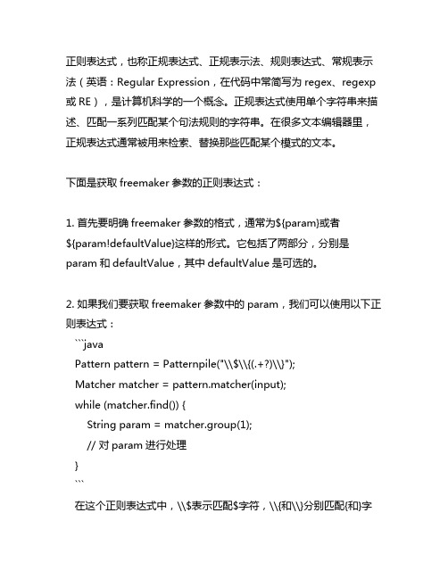
下面是获取freemaker参数的正则表达式:1. 首先要明确freemaker参数的格式,通常为${param}或者${param!defaultValue}这样的形式。
它包括了两部分,分别是param和defaultValue,其中defaultValue是可选的。
2. 如果我们要获取freemaker参数中的param,我们可以使用以下正则表达式:```javaPattern pattern = Patternpile("\\$\\{(.+?)\\}");Matcher matcher = pattern.matcher(input);while (matcher.find()) {String param = matcher.group(1);// 对param进行处理}```在这个正则表达式中,\\$表示匹配$字符,\\{和\\}分别匹配{和}字符,(.+?)表示匹配任意字符,并且使用非贪婪模式,最终获取匹配到的param。
3. 如果我们要获取freemaker参数中的defaultValue,我们可以使用如下正则表达式:```javaPattern pattern = Patternpile("\\$\\{(.+?)!(.+)\\}");Matcher matcher = pattern.matcher(input);while (matcher.find()) {String param = matcher.group(1);String defaultValue = matcher.group(2);// 对param和defaultValue进行处理}```在这个正则表达式中,与上面不同的是,多了一个!字符,用于分隔param和defaultValue,通过使用(.+)匹配任意字符的方式获取defaultValue。
coin3d基础

*
*
*
* *
Option #2: Use an existing SDK
Open Inventor/Coin3D Performer, OpenSG, Java3D,...
14
Coin3D Overview
* * *
*
C++ object oriented high-level 3D graphics API Available as Free Software under the GNU GPL Portable across a wide range of platforms
*
*
Direct3D
Microsoft Windows' proprietary 3D library.
7
So how does this work?
*
*
Most widely used library for 3D graphics is OpenGL.
Cross-platform standard, very flexible, very fast.
SoQt for cross-platform applications using Qt Others (SoXt, SoWin, Sc21)
*
*
C++ SDK
Bindings to other languages available, e.g. Pivy for Python
15
Hello World
*
* *
Property nodes
OpenGL state Inventor state
houdini 表达式路径写法 -回复

houdini 表达式路径写法-回复Houdini是一款功能强大的3D计算机图形软件,被广泛应用于电影、动画、游戏等领域。
在Houdini中,表达式路径写法是一个重要的特性,它能够帮助用户在创建复杂的图形效果时更加方便、高效地操作对象、属性和参数。
本文将详细介绍Houdini表达式路径的写法,从基础使用到高级技巧,一步一步回答读者关于这个主题的问题。
第一节:基础知识1. 什么是表达式路径?表达式路径是一种用来描述Houdini中对象、属性和参数之间关系的字符串。
它由一系列路径名和特殊字符组成,可以用来定位和操作指定的对象或属性。
2. 表达式路径的基本写法是什么?表达式路径的基本写法是用小括号"()" 将路径名括起来。
路径名通常是由一系列节点名和节点索引组成的字符串,用斜杠"/" 进行分隔。
例如,如果你想引用场景中的一个节点,可以使用"(obj/node)" 这样的表达式路径。
3. 表达式路径中如何引用属性或参数?在表达式路径中引用属性或参数需要使用大括号"{}" 将属性或参数名括起来,并与路径名一起组成完整的表达式路径。
例如,"(obj/node {attribute})" 可以用来引用指定节点上的某个属性。
第二节:进阶技巧4. 如何在表达式路径中使用通配符?通配符是一种特殊的字符,可以代表任意字符或字符序列。
在Houdini 的表达式路径中,使用星号"*" 来表示通配符。
例如,如果你想引用所有名称以"box" 开头的节点,可以用"(obj/box*)" 这样的表达式路径。
5. 如何在表达式路径中使用索引?在Houdini的表达式路径中,可以使用方括号"[]" 来引用对象的索引值。
例如,"(obj/box[0])" 可以用来引用场景中第一个名字为"box" 的节点。
bigfoot函数-概述说明以及解释

bigfoot函数-概述说明以及解释1.引言1.1 概述Bigfoot函数是一种强大的编程工具,它在现代软件开发领域扮演着重要的角色。
该函数的名字来自于传说中的大脚怪,象征着它的巨大能力和不可思议之处。
Bigfoot函数不仅仅是一个简单的函数,而是一个功能丰富、灵活可扩展的工具,可以提供一系列的操作和处理功能,大大简化了编程过程。
它像大脚怪一样,在开发过程中大步向前,解决了许多常见的编程难题。
这个函数的定义和功能非常广泛,可以根据实际需求进行定制和拓展。
它可以用于各种编程语言和平台,可以处理各种类型的数据和任务。
无论是数据处理、算法优化、图形渲染还是网络通信,Bigfoot函数都能发挥出色的作用。
它的强大功能包括但不限于:数据转换、排序过滤、计算统计、文件操作、网络请求、图形绘制等等。
除了基本的功能之外,Bigfoot函数还具有出色的性能和可扩展性。
它经过精心设计和优化,可以处理大规模数据和复杂任务,给程序带来极大的效率提升。
同时,它支持插件和扩展模块的集成,使其能够满足不同编程需求,并适应技术的不断变化和发展。
在实际应用中,Bigfoot函数发挥了巨大的作用。
它可以用于开发各种软件和应用程序,解决现实世界中的各种问题。
无论是数据科学、人工智能、物联网还是金融分析,都离不开Bigfoot函数的支持。
它为开发者提供了灵活和高效的工具,使他们能够更快、更好地完成任务,并为程序的稳定性和可靠性提供保障。
总而言之,Bigfoot函数是一种功能强大、多用途的编程工具,具有重要的实用价值和广泛的应用前景。
它的出现不仅丰富了编程工具的选择,也为开发者提供了更多创造和探索的机会。
随着技术的不断进步和发展,Bigfoot函数有望在未来取得更大的突破和应用拓展,为软件开发领域带来更多的惊喜和可能性。
1.2 文章结构文章结构部分的内容如下:文章采用以下结构进行组织和展开:第一部分为引言部分,主要包括三个小节。
首先,概述部分将简单介绍Bigfoot函数的背景和概念。
x2apic logical id规律

x2apic logical id规律
x2APIC(Extended Advanced Programmable Interrupt Controller)是一种用于处
理器中断控制的扩展功能,它提供了更高的性能和灵活性。
在x2APIC中,每个处
理器核心都有一个唯一的逻辑ID(Logical ID)。
对于x2APIC的逻辑ID规律,以下是一些常见的描述:
1. 递增规律:逻辑ID可能按照递增的顺序分配给处理器核心。
例如,第一个
核心可能被分配逻辑ID 0,第二个核心被分配逻辑ID 1,以此类推。
这种规律可
以使系统更容易管理和识别核心的分配情况。
2. 特定规律:逻辑ID可能根据硬件架构的特定规则进行分配。
这可能包括根
据物理位置或其他特征来确定逻辑ID。
这种规律可以使系统更有效地利用处理器
核心的资源。
3. 自定义规律:逻辑ID可能根据系统管理员的需求进行自定义分配。
例如,
可以根据特定应用程序的需求为每个核心分配逻辑ID。
这种规律可以根据具体的
应用场景进行优化。
需要注意的是,由于x2APIC规范没有规定逻辑ID的具体分配方式,因此不
同的处理器和系统可能会采用不同的规律。
具体的逻辑ID规律可以在处理器或系
统的文档中找到。
总结而言,x2APIC逻辑ID的规律可能包括递增规律、特定规律或自定义规律。
根据具体的硬件架构和系统需求,逻辑ID的分配方式可能有所不同。
了解逻辑ID
规律对于系统管理和优化非常重要,因此建议在使用x2APIC功能时详细查阅相关
文档和资料。