VerilogHDL实例
【连载】FPGAVerilogHDL系列实例--------4位二进制加减法计数器

【连载】FPGAVerilogHDL系列实例--------4位⼆进制加减法计数器Verilog HDL 之 4位⼆进制加减法计数器⼀、原理 计数器是数字系统中⽤的较多的基本逻辑器件。
它不仅能记录输⼊时钟脉冲的个数,还可以实现分频、定时等功能。
计数器的种类很多。
按脉冲⽅式可以分为同步计数器和异步计数器;按进制可以分为⼆进制计数器和⾮⼆进制计数器;按计数过程数字的增减,可分为加计数器、减计数器和可逆计数器。
本实验就是设计⼀个4位⼆进制加减法计数器,该计数器可以通过⼀个控制信号决定计数器时加计数还是减计数,另外,该寄存器还有⼀个清零输⼊,低电平有效。
还有⼀个load装载数据的信号输⼊,⽤于预置数据;还有⼀个C的输出,⽤于计数器的级联。
其功能表如表1.1所⽰; 表1.1 4位⼆进制加减法计数器功能表⼆、实现在设计⽂件中输⼊Verilog代码1/****************************** 分频模块 *************************************/23 `timescale 1 ns / 1 ps4 module qu_dou ( clk ,rst , a ,b );56 input clk ;7 wire clk ;8 input rst ;9 input a ;10 wire a ;1112 output b ;13 reg b ;1415 reg [31:0] cnt ;16 reg clkout ;17 always @ ( posedge clk or negedge rst )18 begin19if ( rst == 1'b0 )20 cnt <= 0 ;21else begin if ( a==1'b1 ) begin22if ( cnt >= 32'd3000000 )23 b <= 1 ;24else25 cnt <= cnt + 1'b1 ;2627 end28else begin b <= 1'b0 ;29 cnt <= 0 ;30 end31 end32 end333435 endmodule功能实现1 `timescale 1 ns / 1 ps23 module counter4 ( load ,clr ,c ,DOUT ,clk, up_down ,DIN ,sysclk , rst );45 input load ;6 input clk;7 wire load ;8 input clr ;9 wire clr ;10 input up_down ;11 wire up_down ;12 input [3:0] DIN ;13 wire [3:0] DIN ;14 input sysclk ;15 input rst ;1617 output c ;18 reg c ;19 output [3:0] DOUT ;20 wire [3:0] DOUT ;21 reg [3:0] data_r;2223/***************** 例化去抖模块 *************************************/24 wire clk_r ;25 qu_dou qu_dou (26 .clk (sysclk) ,27 .rst (rst) ,28 .a (clk),29 .b (clk_r));3031//********************************************************************* 323334 assign DOUT = data_r;35 always @ ( posedge clk_r or posedge clr or posedge load)36 begin37if ( clr == 1) //同步清零38 data_r <= 0;39else if ( load == 1) //同步预置40 data_r <= DIN;41else begin if ( up_down ==1)42 begin43if ( data_r == 4'b1111) begin //加计数44 data_r <= 4'b0000;45 c = 1;46 end47else begin //减计数48 data_r <= data_r +1;49 c = 0 ;50 end51 end52else53 begin54if ( data_r == 4'b0000) begin //加计数55 data_r <= 4'b1111;56 c = 1;57 end58else begin //减计数59 data_r <= data_r -1;60 c = 0 ;61 end62 end63 end64 end65 endmodule。
Verilog_HDL综合设计实例(自动乐曲演奏)

Place & Route
Timing Analysis
基于FPGA的乐曲自动演奏器设计
FPGA
产生音符所对应频率的方波信号
在输入参考频率fc=3MHz时, 计算简谱中所有音符的分频系 数。
实际上,只要各个 音符之间的相对频率关 系不变,演奏出的音乐 听起来就不会“走调”。
1. 一.设计目的与要求
音名显示电路用来显示乐曲演奏时对应的 音符。可以用3个数码管,分别显示高、 中、低音的音名,实现演奏的动态显示, 十分直观。在本例中,high[3:0]、 med[3:0]、low[3:0]等信号分别用于显示高 音、中音、低音音符。为了使演奏能循环 进行,需另外设置一个时长计数器,当乐 曲演奏完成时,保证能自动从头开始演奏。
4)12MHz分频成1mhz波形分频器,源代码和顶层模块如下: //12mhz分成1mhz的分频模块,提供给quma模块 module div_clk1mhz(clk_12mhz,clk_1mhz); input clk_12mhz; output clk_1mhz; reg clk_1mhz; reg [21:0] cnt; always @(posedge clk_12mhz) if(cnt<5) cnt=cnt+1; // (12mhz/1mhz=12,cnt<[12/2-1=5]) else begin cnt=0; clk_1mhz =! clk_1mhz; end Endmodule
用纯硬件完成乐曲演奏电路的设计与利用微处 理器(CPU)实现相比逻辑要复杂得多,如不借助 于功能强大的EDA工具和硬件描述语言,仅凭传 统的数字逻辑技术,即使最简单的演奏电路也难以 实现。
FPGA Verilog HDL 系列实例--8-3编码器

Verilog HDL 之直流电机PWM控制一、实验前知识准备在上一篇中总结了步进电机的控制,这次我将学习一下直流电机的控制,首先,我们简要了解下步进电机和直流电机的区别。
(1)步进电机是以步阶方式分段移动,直流电机通常采用连续移动的控制方式。
(2)步进电机采用直接控制方式,它的主要命令和控制变量都是步阶位置;直流电机则是以电机电压为控制变量,以位置或速度为命令变量。
(3)直流电机需要反馈控制系统,他会以间接方式控制电机位置。
步进电机系统多半以“开环方式”进行操作。
1、什么是直流电机输出或输入为直流电能的旋转电机,称为直流电机,它是能实现直流电能和机械能互相转换的电机。
当它作电动机运行时是直流电动机,将电能转换为机械能;作发电机运行时是直流发电机,将机械能转换为电能。
2、什么是PWMPWM(脉冲宽度调制)是一种模拟控制方式,其根据相应载荷的变化来调制晶体管栅极或基极的偏置,来实现开关稳压电源输出晶体管或晶体管导通时间的改变,这种方式能使电源的输出电压在工作条件变化时保持恒定,是利用微处理器的数字输出来对模拟电路进行控制的一种非常有效的技术。
3、开发平台中直流电机驱动的实现开发板中的直流电机的驱动部分如图1.1所示。
利用FPGA设计一个0、1组成的双极性PWM发生器。
图1.1 直流电机的驱动部电路二、实验平台Quartus II 7.2 集成开发环境、SOPC-MBoard板、ByteBlaster II 下载电缆三、实验目标1、了解直流电机PWM的控制方法。
2、具有调速功能。
四、实验实现详细实现步骤请参考【连载】FPGA Verilog HDL 系列实例--------8-3编码器1、在设计文件中输入Verilog代码。
66 endmodule2、分析思考:(1)如何控制顺时针转和逆时针转?(2)速度的大小如何控制的?第38行~第53行:由2个引脚控制生成双极性PWM发生器。
结论:(1)以MA_r[0]为准,当状态0的时间大于状态1的时间时,电机逆时针转动;反之,电机顺时针转动。
005 Verilog HDL 设计实例

wire din; wire clk; wire r; wire dout;
reg [7:0]shift_register;
module p(din,clk,r,dout,x0,x1,x2,x3,x4,x5,x6); input din; input clk; input r; //异步复位,低电平有效(复位) output dout,x0,x1,x2,x3,x4,x5,x6; wire din; wire clk; wire r; wire dout,x1,x2,x3,x4,x5,x6,x7;
wire din; wire clk; wire r; wire [7:0]dout;
reg [7:0]shift_register;
• 带有同步置位的8位循环移位寄存器,它能够在时 钟的作用下将寄存器中的数据循环左移或右移。
module o(load,clk,dir,data,q); input clk,load; input [7:0]data; input dir; //方向选择信号,dir=1时右移,否则左移 output q; wire clk,load,dir; wire [7:0]data; wire q; reg [7:0]shift_register; always @(posedge clk) begin if(load==1) shift_register<=data; else if(dir==1) begin shift_register[7]=shift_register[0]; shift_register[6:0]=shift_register[7:1]; end else begin shift_register[0]=shift_register[7]; shift_register[7:1]=shift_register[6:0]; end end assign q=shift_register[7]; endmodule
verilog hdl语言100例详解

verilog hdl语言100例详解Verilog HDL语言是一种硬件描述语言,用于描述数字电路和系统的行为和结构。
它是硬件设计工程师在数字电路设计中的重要工具。
本文将介绍100个例子,详细解释Verilog HDL语言的应用。
1. 基本门电路:Verilog HDL可以用于描述基本门电路,如与门、或门、非门等。
例如,下面是一个描述与门电路的Verilog HDL代码:```verilogmodule and_gate(input a, input b, output y);assign y = a & b;endmodule```2. 多路选择器:Verilog HDL也可以用于描述多路选择器。
例如,下面是一个描述2:1多路选择器的Verilog HDL代码:```verilogmodule mux_2to1(input a, input b, input sel, output y);assign y = sel ? b : a;endmodule```3. 寄存器:Verilog HDL可以用于描述寄存器。
例如,下面是一个描述8位寄存器的Verilog HDL代码:```verilogmodule register_8bit(input [7:0] d, input clk, input reset, output reg [7:0] q);always @(posedge clk or posedge reset)if (reset)q <= 0;elseq <= d;endmodule```4. 计数器:Verilog HDL可以用于描述计数器。
例如,下面是一个描述8位计数器的Verilog HDL代码:```verilogmodule counter_8bit(input clk, input reset, output reg [7:0] count);always @(posedge clk or posedge reset)if (reset)count <= 0;elsecount <= count + 1;endmodule```5. 加法器:Verilog HDL可以用于描述加法器。
verilog的15个经典设计实例
begin b=a; c=b; end endmodule
【例 5.11】模为 60 的 BCD 码加法计数器
module count60(qout,cout,data,load,cin,reset,clk);
【例 5.6】用 fork-join 并行块产生信号波形
`timescale 10ns/1ns module wave2; reg wave; parameter cycle=5; initial
fork wave=0;
#(cycle) wave=1; #(2*cycle) wave=0; #(3*cycle) wave=1; #(4*cycle) wave=0; #(5*cycle) wave=1; #(6*cycle) $finish; join initial $monitor($time,,,"wave=%b",wave); endmodule
else
out<=out+1;
end
endmodule
//同步复位 //计数
【例 3.3】4 位全加器的仿真程序
`timescale 1ns/1ns `include "adder4.v" module adder_tp; reg[3:0] a,b; reg cin; wire[3:0] sum; wire cout; integer i,j;
output[7:0] qout;
output cout;
input[7:0] data;
input load,cin,clk,reset;
Verilog的135个经典设计实例
endmodule
【例 3.2】 4 位计数器
module count4(out,reset,clk); output input [3:0] out; reset,clk;
reg [3:0] out; always @( posedge clk)
begin if else end endmodule (reset) out<=0; out<=out+1; // 同步复位 // 计数
endmodule
【例 3.5】 “与 - 或 -非”门电路
module AOI(A,B,C,D,F); input output A,B,C,D; F; // 模块名为 AOI( 端口列表 A, B, C, D, F) // 模块的输入端口为 // 模块的输出端口为 A, B, C,D F
-2 -
begin if (qout[3:0]==9) begin qout[3:0]<=0; if (qout[7:4]==5) qout[7:4]<=0; // 回 0 ,并判断高位是否为 5 // 低位是否为 9 ,是则
else qout[7:4]<=qout[7:4]+1; end else qout[3:0]<=qout[3:0]+1; end end assign cout=((qout==8'h59)&cin)?1:0; // 产生进位输出信号 // 低位不为 9 ,则加 1 // 高位不为 5 ,则加 1
王金明: 《 Verilog HDL wire A,B,C,D,F; assign endmodule F= ~((A&B)|(C&D)); // 定义信号的数据类型 // 逻辑功能描述
verilog hdl应用程序设计实例精讲

verilog hdl应用程序设计实例精讲网上现在有很多关于verilog hdl应用程序设计的资料,但是并没有一个很系统和全面的教程来帮助初学者快速入门。
本文就verilog hdl应用程序设计实例进行了精讲,从基本概念到应用实例一步一步地回答了初学者的问题,帮助大家理解verilog hdl的设计和应用。
一、verilog hdl的基本概念Verilog HDL是一种硬件描述语言,用于描述数字系统,包括逻辑电路、集成电路等等。
它既可以进行仿真验证,也可以直接生成硬件电路。
简单来说,verilog hdl就是一种用来描述数字系统的语言。
1.1 模块与实例化在verilog hdl中,模块是最基本的设计单元,每个模块包含一个或多个端口和内部逻辑电路。
模块可以包含其他模块,这被称为实例化。
实例化可以理解为创建一个模块的实例,并根据实例进行连接。
1.2 端口和内部信号模块的端口是与其他模块或外部电路连接的接口,可以是输入、输出或双向。
内部信号是模块内部产生和使用的信号,只在模块内部可见。
1.3 组合逻辑与时序逻辑组合逻辑是指只有输入信号改变时才会改变输出信号的逻辑电路,而时序逻辑是指输出信号的改变还受到时钟信号的控制。
在verilog hdl中,可以使用逻辑门、逻辑运算符和条件语句来实现组合逻辑和时序逻辑。
二、verilog hdl应用程序设计实例接下来,我们通过一些实例来展示verilog hdl的应用程序设计。
2.1 4位全加器我们首先来实现一个4位全加器。
全加器是用来实现两个二进制数的加法的电路,它能够实现两个输入和一个进位的相加操作,输出结果和进位。
在verilog hdl 中,可以使用逻辑运算符和条件语句来实现全加器。
2.2 4位加法器我们可以使用四个全加器来实现一个4位加法器。
加法器是用来实现两个二进制数的加法的电路,它能够实现多位的相加操作,输出结果和进位。
2.3 4位计数器计数器是一种能够实现计数功能的电路,它能够根据时钟信号进行计数,并在达到一定数值时输出特定信号。
VerilogHDL通用时序设计示例

state <= Start; G<=0;
start: Stop:
Clear:
end if (!A) state <= Stop; begin if (A) state <= Clear; F <= 1; end begin if (!A) state <=Idle; F<=0; G<=1; end
Start = 2'b01, 2' 2' Clear = 2'b11;
always @(posedge Clock) if (!Reset) begin state <= Idle; end else case (state) Idle: if (A) Start: if (!A) Stop: if (A) Clear: if (!A) default: state <= endcase
A/G=0 !Reset/F=0 G=0 !Reset /F=0 G=0
Start
!A
Idle
!Reset /F=0 G=0
Stop
!Reset | !A/F=0 G=1
Clear
A/F=1
module fsm (Clock, Reset, A, input Clock, Reset, A; output F,G; reg F,G; reg [1:0] state ; parameteodule
推荐:另一种风格的Verilog HDL模型来表示同一个 模型来表示同一个有限状态 推荐:另一种风格的Verilog HDL模型来表示同一个有限状态 在这个模型中,我们把 always语句在时钟沿触发条件下 .在这个模型中,我们把用always语句在时钟沿触发条件下 的状态变化放在一个独立的块中, 的状态变化放在一个独立的块中, 而把在状态控制下的两个 输出分两个独立的组合逻辑always块来描述.见下例: 组合逻辑always 输出分两个独立的组合逻辑always块来描述.见下例: module fsm (Clock, Reset, A, input Clock, Reset, A; output F,G; reg [1:0] state ; reg F,G; parameter Idle = 2'b00, 2' 2' Stop = 2'b10, F, G);
Verilog HDL举例5
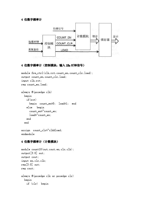
4 位数字频率计4 位数字频率计(控制模块,输入1Hz时钟信号)module fre_ctrl(clk,rst,count_en,count_clr,load); output count_en,count_clr,load;input clk,rst;reg count_en,load;always @(posedge clk)beginif(rst)begin count_en=0; load=1; endelse begincount_en=~count_en;load=~count_en;endendassign count_clr=~clk&load;endmodule4 位数字频率计(计数模块)module count10(out,cout,en,clr,clk);output[3:0] out;output cout;input en,clr,clk;reg[3:0] out;reg cout;always @(posedge clk or posedge clr)beginif (clr) beginout = 0;cout = 0;endelse if(en)beginif(out==9) beginout=0;cout = 1;endelse beginout = out+1;cout = 0;endendendendmodule4 位数字频率计(锁存器模块)module latch_16(qo,din,load); output[15:0] qo;input[15:0] din;input load;reg[15:0] qo;always @(posedge load)begin qo=din; end endmodule4 位数字频率计(顶层模块)交通灯控制器module traffic(CLK,EN,LAMPA,LAMPB,ACOUNT,BCOUNT);output[7:0] ACOUNT; //A方向灯的时间显示output[7:0] BCOUNT; //B方向灯的时间显示output[3:0] LAMPA; //控制A方向4盏灯的亮灭,分别对应红、黄、绿、左拐output[3:0] LAMPB; //控制B方向4盏灯的亮灭input CLK,EN;reg[7:0] numa,numb;reg tempa,tempb;reg[2:0] counta,countb;reg[7:0] ared,ayellow,agreen,aleft,bred,byellow,bgreen,bleft;reg[3:0] LAMPA,LAMPB;always @(EN)if(!EN)beginared <=8'h55;ayellow <=8'h5;agreen <=8'h40;aleft <=8'h15;bred <=8'h65;byellow <=8'h5;bleft <=8'h15;bgreen <=8'h30;endassign ACOUNT=numa;assign BCOUNT=numb;always @(posedge CLK)beginif(EN)beginif(!tempa)begintempa<=1;case(counta)0: begin numa<=agreen; LAMPA<=2; counta<=1; end1: begin numa<=ayellow; LAMPA<=4; counta<=2; end2: begin numa<=aleft; LAMPA<=1; counta<=3; end3: begin numa<=ayellow; LAMPA<=4; counta<=4; end4: begin numa<=ared; LAMPA<=8; counta<=0; enddefault: LAMPA<=8;endcaseendelse beginif(numa>1)if(numa[3:0]==0) beginnuma[3:0]<=4'b1001;numa[7:4]<=numa[7:4]-1;endelse numa[3:0]<=numa[3:0]-1;if (numa==2) tempa<=0;endendelse beginLAMPA<=4'b1000;counta<=0; tempa<=0;endendalways @(posedge CLK)beginif (EN)beginif(!tempb)begintempb<=1;case (countb)0: begin numb<=bred; LAMPB<=8; countb<=1; end 1: begin numb<=bgreen; LAMPB<=2; countb<=2; end 2: begin numb<=byellow; LAMPB<=4; countb<=3; end 3: begin numb<=bleft; LAMPB<=1; countb<=4; end 4: begin numb<=byellow; LAMPB<=4; countb<=0; end default: LAMPB<=8;endcaseendelsebeginif(numb>1)if(!numb[3:0]) beginnumb[3:0]<=9;numb[7:4]<=numb[7:4]-1;endelse numb[3:0]<=numb[3:0]-1;if(numb==2) tempb<=0;endendelse beginLAMPB<=4'b1000;tempb<=0; countb<=0;endendendmodule乐曲演奏电路module song(clk_6MHz,clk_4Hz,speaker,high,med,low); input clk_6MHz, clk_4Hz;output speaker;output[3:0] high,med,low;reg[3:0] high,med,low;reg[13:0] divider,origin;reg[7:0] counter;reg speaker;wire carry;assign carry=(divider==16383);always @(posedge clk_6MHz)beginif(carry) divider=origin;else divider=divider+1;endalways @(posedge carry)beginspeaker=~speaker;endalways @(posedge clk_4Hz)begincase({high,med,low})'b000000000011: origin=7281;'b000000000101: origin=8730;'b000000000110: origin=9565;'b000000000111: origin=10310;'b000000010000: origin=10647;'b000000100000: origin=11272;'b000000110000: origin=11831;'b000001010000: origin=12556;'b000001100000: origin=12974;'b000100000000: origin=13516;'b000000000000: origin=16383; endcaseendalways @(posedge clk_4Hz)beginif(counter==63) counter=0;else counter=counter+1; case(counter)0: {high,med,low}='b000000000011; 1: {high,med,low}='b000000000011; 2: {high,med,low}='b000000000011; 3: {high,med,low}='b000000000011; 4: {high,med,low}='b000000000101; 5: {high,med,low}='b000000000101; 6: {high,med,low}='b000000000101; 7: {high,med,low}='b000000000110; 8: {high,med,low}='b000000010000; 9: {high,med,low}='b000000010000; 10: {high,med,low}='b000000010000; 11: {high,med,low}='b000000100000; 12: {high,med,low}='b000000000110; 13: {high,med,low}='b000000010000; 14: {high,med,low}='b000000000101; 15: {high,med,low}='b000000000101;16: {high,med,low}='b000001010000; 17: {high,med,low}='b000001010000; 18: {high,med,low}='b000001010000; 19: {high,med,low}='b000100000000; 20: {high,med,low}='b000001100000; 21: {high,med,low}='b000001010000; 22: {high,med,low}='b000000110000; 23: {high,med,low}='b000001010000; 24: {high,med,low}='b000000100000; 25: {high,med,low}='b000000100000; 26: {high,med,low}='b000000100000; 27: {high,med,low}='b000000100000; 28: {high,med,low}='b000000100000; 29: {high,med,low}='b000000100000; 30: {high,med,low}='b000000100000;31: {high,med,low}='b000000100000;32: {high,med,low}='b000000100000; 33: {high,med,low}='b000000100000; 34: {high,med,low}='b000000100000; 35: {high,med,low}='b000000110000; 36: {high,med,low}='b000000000111; 37: {high,med,low}='b000000000111; 38: {high,med,low}='b000000000110; 39: {high,med,low}='b000000000110; 40: {high,med,low}='b000000000101; 41: {high,med,low}='b000000000101; 42: {high,med,low}='b000000000101; 43: {high,med,low}='b000000000110; 44: {high,med,low}='b000000010000; 45: {high,med,low}='b000000010000; 46: {high,med,low}='b000000100000; 47: {high,med,low}='b000000100000;48: {high,med,low}='b000000000011; 49: {high,med,low}='b000000000011; 50: {high,med,low}='b000000010000; 51: {high,med,low}='b000000010000; 52: {high,med,low}='b000000000110; 53: {high,med,low}='b000000000101; 54: {high,med,low}='b000000000110; 55: {high,med,low}='b000000010000; 56: {high,med,low}='b000000000101; 57: {high,med,low}='b000000000101; 58: {high,med,low}='b000000000101; 59: {high,med,low}='b000000000101; 60: {high,med,low}='b000000000101; 61: {high,med,low}='b000000000101; 62: {high,med,low}='b000000000101; 63: {high,med,low}='b000000000101; endcaseendendmodule自动售货机module sell(one_dollar,half_dollar,collect,half_out,reset,clk); parameter idle=0, half=1, one=2, one_half =3, two=4;input one_dollar,half_dollar,reset,clk;output collect; //取货物output half_out; //找零reg collect,half_out;reg[2:0] D;always @(posedge clk)beginif(reset)begincollect=0;half_out=0;D=idle;endcase(D)idle:if(half_dollar) D=half;else if(one_dollar) D=one;half:if(half_dollar) D=one;else if(one_dollar) D= one_half;one:if(half_dollar) D= one_half;else if(one_dollar) D=two;one_half:if(half_dollar) D= two;else if(one_dollar)begincollect=1;D=idle;endtwo:if(half_dollar)begincollect=1;D=idle;endelse if(one_dollar)begincollect=1;half_out=1;D=idle;endendcaseendendmodule。
简单自动售货机VerilogHDL程序
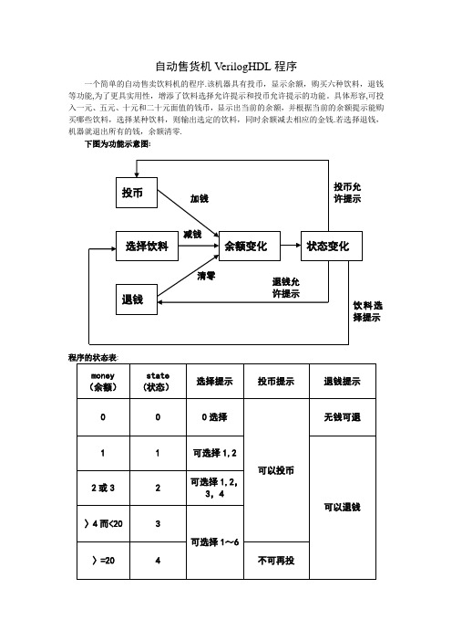
自动售货机VerilogHDL程序一个简单的自动售卖饮料机的程序.该机器具有投币,显示余额,购买六种饮料,退钱等功能,为了更具实用性,增添了饮料选择允许提示和投币允许提示的功能。
具体形容,可投入一元、五元、十元和二十元面值的钱币,显示出当前的余额,并根据当前的余额提示能购买哪些饮料,选择某种饮料,则输出选定的饮料,同时余额减去相应的金钱.若选择退钱,机器就退出所有的钱,余额清零.下图为功能示意图:程序的状态表:程序中包含了一个状态机,定义了一个任务(task)和函数(function),用该任务调用了该函数,使用若干分支语句,详见附后源程序和测试程序。
附上程序编译仿真图:源程序如下:`define one 3'b001`define five 3'b010`define ten 3'b011`define twenty 3’b100module automart(money,state,moneyout,coinable,adrkable,bdrkable,cdrkable,drkout1,drkout2,drkout3,drkout4,drkout5,drkout6,coin,clk,reset,moneyback,choice1,choice2,choice3,choice4,choice5,choice6);input[2:0]coin;//投币输入,分为1、5、10、20元四种输入input clk,reset,moneyback,choice1,choice2,choice3,choice4,choice5,choice6;//moneyback为退钱输入,choice1~6是饮料选择output moneyout,coinable,adrkable,bdrkable,cdrkable,drkout1,drkout2,drkout3,drkout4,drkout5,drkout6;//依次为退钱输出,投币许可提示,饮料选择许可,6种饮料输出output[2:0] state;//状态记录output[7:0] money;//余额显示reg[7:0] money;reg[2:0] state;reg moneyout,coinable,backable,adrkable,bdrkable,cdrkable; parameter A=3'b000,B=3'b001,C=3'b010,D=3'b011,E=4’b100;assign drkout1=choice1&adrkable;assign drkout2=choice2&adrkable;assign drkout3=choice3&bdrkable;assign drkout4=choice4&bdrkable;assign drkout5=choice5&cdrkable;assign drkout6=choice6&cdrkable;always@(posedge clk)repeat(1)@(posedge clk)if (!reset)beginstate<=A;money=0;moneyout=0;endelsebegincase(state)A:begin//初始状态A,可投币进入别的状态coinable=1;backable=0;adrkable=0;bdrkable=0;cdrkable=0;endB: begin//状态B,只能买1元的饮料,可退钱或投币coinable=1;backable=1;adrkable=1;bdrkable=0;cdrkable=0;endC: begin//状态C,可买1或2元的饮料,退钱或投币coinable=1;backable=1;adrkable=1;bdrkable=1;cdrkable=0;endD:begin//状态D,可买三档价格饮料,可退钱或投币coinable=1;backable=1;adrkable=1;bdrkable=1;cdrkable=1;endE:begin//状态E,可买三档价格饮料,可退钱,不可继续投钱coinable=0;backable=1;adrkable=1;bdrkable=1;cdrkable=1;enddefault: state=A;endcasecondition(money,state,coin,coinable);//调用任务endalways@(negedge drkout1 or negedge drkout2)money=money—8’h01;//买1元的饮料,余额减1元always@(negedge drkout3 or negedge drkout4)money=money—8'h02;//买2元的饮料,余额减2元always@(negedge drkout5 or negedge drkout6)money=money—8'h04;//买4元的饮料,余额减4元always@(negedge moneyback)beginif(backable)beginmoneyout=1;money=0;//选择退钱,则推出金钱,余额清零endelsemoney=money+0;endtask condition;//该任务可以判断余额的改变,状态切换inout[7:0] moneycon;inout[2:0] statecon;input[2:0] coincon;input coinablecon;beginif (coinablecon)//允许投币时begincase (coincon)//根据投币面值改变余额,切换状态`one : moneycon=moneycon+8'h01;`five :moneycon=moneycon+8'h05;`ten : moneycon=moneycon+8'h0a;`twenty :moneycon=moneycon+8'h14;default:moneycon=moneycon+0;//无投币则余额不变endcasestatecon=condition_s(moneycon);//调用函数endelse if (moneycon〈8’h14)//不允许投币时,根据余额变化statecon=condition_s(moneycon);//直接切换状态endendtaskfunction [2:0] condition_s;//根据余额的值切换状态的函数input [7:0] money_s;reg [7:0]money_s;beginif (money_s==0)condition_s=A;else if(money_s==8’h01)condition_s=B;else if(money_s==8’h02||money_s==8’h03)condition_s=C;else if(money_s〉=8’h04&&money_s〈8’h14)condition_s=D;else condition_s=E;endendfunctionendmodule测试程序如下:`timescale 100ns/1ns`define clk_cycle 50module test;reg moneyback,choice1,choice2,choice3,choice4,choice5,choice6; reg [2:0] coin;reg clk,reset;wire[7:0] money;wire[2:0]state;wire moneyout,coinable,adrkable,bdrkable,cdrkable,drkout1,drkout2,drkout3,drkout4,drkout5,drkout6;parameter one=3’b001,five=3’b010,ten=3'b011,twenty=3'b100;always #`clk_cycle clk= ~clk;initialbegincoin=0;moneyback=0;clk=0;choice1=0;choice2=0;choice3=0;choice4=0;choice5=0;choice6=0;reset=1;#10 reset=0;#200 reset=1;#400 coin=one;//投币1元,#220 coin=0;#200 coin=one;//投1元,余额2元#220 coin=0;#200 coin=five;//投5元,余额7元#220 coin=0;#200 coin=twenty;//投20元,余27#220 coin=0;#200 choice1=1;//买1元饮料,余26#220 choice1=0;#200 choice3=1;//买2元饮料,余24#220 choice3=0;#200 choice4=1;//买2元饮料,余22#220 choice4=0;#200 choice5=1;//买4元饮料,余18#220 choice5=0;#200 choice6=1;//买4元饮料,余14#220 choice6=0;#200 choice6=1;//买4元饮料,余10#220 choice6=0;#200 choice6=1;//买4元饮料,余6#220 choice6=0;#200 choice6=1;//买4元饮料,余2#220 choice6=0;#200 coin=five;//投5元,余7#220 coin=0;#200 moneyback=1;//退钱#220 moneyback=0;endautomart m(.money(money),。
VerilogHDL第五讲Verilog实例

input [3:0] data_in ;
input EN ; output [6:0] data_out ;
reg [6:0] data_out ; always @(data_in or EN ) begin
data_out = 7'b1111111; if (EN == 1)
clk,clrb;
input[3:0]
d;
output[3:0] q;
flop f1(d[0],clk,clrb,q[0],),
f2(d[1],clk,clrb,q[1],),
f3(d[2],clk,clrb,q[2],),
f4(d[3],clk,clrb,q[3],);
endmodule
第17页,共38页。
第五讲 门电路的描述和设 计实例
第1页,共38页。
5.1基本门电路的描述
一个逻辑电路是由许多逻辑门和开关所组成, 因此用逻辑门的模型来描述逻辑电路结构 是最直观的。VerilogHDL提供了一些描述 门类型的关键字,可以用于门级结构建模。
VerilogHDL内含的基本元件模型共有26种, 其中14种为基本门级元件,12种为开关级 元件,
第4页,共38页。
5.1.2基本门的逻辑真值表
Nand和nor真值表
nand 0 1 x z nor 0 1 x z
0 1 1 110 1 1 0 xx1 x 1 x xxx z 1 x xxz
10xx 0000 x0xx x0xx
第5页,共38页。
Xor和xnor真值表
xor 0 1 x z xnor 0 1 x z
VerilogHDL程序设计实例详解

6.2 SPI Master Controller设 计
6.2.3 串行接口层模块设计 4
6 SPI Master Controller实例
6.3.1 spi_top Testbench总体构架
1
6.3.2 模拟Wishbone master模块
及仿真波形
03
3.4.2 shift_divider Te s t b e n c h 设 计
3.4 移位除法器shift_divider 设计实例
04 4 编码器/译码器实例
4 编码器/译码器实例
4.1 二进制编码器bin_enc设计实 例
4.3 密勒译码器miller_de设计实例
4.2 曼彻斯特编译码器manch_ed 设计实例
03
3.3.3 booth_mult Te s t b e n c h 执 行 结果及仿真波形
3.3 布尔乘法器booth_mult 设计实例
3 乘法器/除法器实例
3.4.1 移位除法器 shift_divider设计
01
02
3.4.3 shift_divider Te s t b e nc h 执 行 结 果
02 2 加法器/计数器实例
2 加法器/计数器实例
2.1 1bit半加法器adder 设计实例
2.3 同步4bit全加法器 adder4设计实例
2.5 8bit BCD码计数器 count60设计实例
2.2 1bit全加法器 full_add设计实例
2.4 4bit计数器count4设 计实例
2 加法器/计数器实例
02
4.3.2 检测模块
signal_detect设计
03
4.3.3 signal_detect
VerilogHDL举例2

VerilogHDL举例2任务举例module alutask(code,a,b,c);input[1:0] code;input[3:0] a,b;output[4:0] c;reg[4:0] c;task my_and;input[3:0] a,b;output[4:0] out;integer i;beginfor(i=3;i>=0;i=i-1)out[i]=a[i]&b[i];endendtaskalways@(code or a or b)begincase(code)2'b00: my_and(a,b,c);2'b01: c=a|b;2'b10: c=a-b;2'b11: c=a+b;endcaseendendmodule测试程序`include "alutask.v"module alu_tp;reg[3:0] a,b;reg[1:0] code;wire[4:0] c;parameter DELY = 100;alutask ADD(code,a,b,c);initial begincode=4'd0; a= 4'b0000; b= 4'b1111; #DELY code=4'd0; a= 4'b0111; b= 4'b1101; #DELY code=4'd1; a= 4'b0001; b= 4'b0011;#DELY code=4'd2; a= 4'b1001; b= 4'b0011;#DELY code=4'd3; a= 4'b0011; b= 4'b0001;#DELY code=4'd3; a= 4'b0111; b= 4'b1001;#DELY $finish;endinitial $monitor($time,"code=%b a=%b b=%b c=%b", code,a,b,c); endmodule在Verilog HDL中使⽤任务(task)设计⽐较后重组信号的组合逻辑的实例。
【连载】FPGAVerilogHDL系列实例--------8-3优先编码器
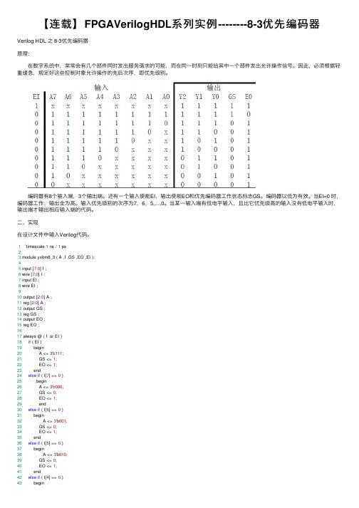
【连载】FPGAVerilogHDL系列实例--------8-3优先编码器Verilog HDL 之 8-3优先编码器原理: 在数字系统中,常常会有⼏个部件同时发出服务请求的可能,⽽在同⼀时刻只能给其中⼀个部件发出允许操作信号。
因此,必须根据轻重缓急,规定好这些控制对象允许操作的先后次序,即优先级别。
编码器有8个输⼊端,3个输出端。
还有⼀个输⼊使能EI,输出使能EO和优先编码器⼯作状态标志GS。
编码器以低为有效。
当EI=0 时,编码器⼯作;输出全为⾼。
输⼊优先级别的次序为7,6,5,…,0。
当某⼀输⼊端有低电平输⼊,且⽐它优先级⾼的输⼊没有低电平输⼊时,输出端才输出相应输⼊端的代码。
⼆、实现在设计⽂件中输⼊Verilog代码。
1 `timescale 1 ns / 1 ps23 module yxbm8_3 ( A ,I ,GS ,EO ,EI );45 input [7:0] I ;6 wire [7:0] I ;7 input EI ;8 wire EI ;910 output [2:0] A ;11 reg [2:0] A ;12 output GS ;13 reg GS ;14 output EO ;15 reg EO ;1617 always @ ( I or EI )18if ( EI )19 begin20 A <= 3'b111;21 GS <= 1;22 EO <= 1;23 end24else if ( I[7] == 0 )25 begin26 A <= 3'b000;27 GS <= 0;28 EO <= 1;29 end30else if ( I[6] == 0 )31 begin32 A <= 3'b001;33 GS <= 0;34 EO <= 1;35 end36else if ( I[5] == 0 )37 begin38 A <= 3'b010;39 GS <= 0;40 EO <= 1;41 end42else if ( I[4] == 0 )43 begin44 A <= 3'b011;45 GS <= 0;46 EO <= 1;47 end48else if ( I[3] == 0 )49 begin50 A <= 3'b100;51 GS <= 0;52 EO <= 1;53 end54else if ( I[2] == 0 )55 begin56 A <= 3'b101;57 GS <= 0;58 EO <= 1;59 end60else if ( I[1] == 0 )61 begin62 A <= 3'b110;63 GS <= 0;64 EO <= 1;65 end66else if ( I[0] == 0 )67 begin68 A <= 3'b111;69 GS <= 0;70 EO <= 1;71 end72else if ( I == 8'b11111111)73 begin74 A <= 3'b111;75 GS <= 1;76 EO <= 0;77 end78 endmodule。
第六章 Verilog HDL高级程序设计举例

10/7/2013
Microelectronics School Xidian University
7
6.2典型电路设计
• 6.2.1加法器树乘法器
加法器树乘法器的设计思想是“移位后加”,并且加法运算采用加法器 树的形式。乘法运算的过程是,被乘数与乘数的每一位相乘并且乘以 相应的权值,最后将所得的结果相加,便得到了最终的乘法结果。 例:下图是一个4位的乘法器结构,用Verilog HDL设计一个加法器树 4位乘法器
module mult_addtree_tb; reg [3:0]mult_a; reg [3:0]mult_b; wire [7:0]mult_out; // module instance mul_addtree U1(.mul_a(mult_a),.mul_b(mult_b),.mul_out(mult_out)); initial //Stimuli signal begin mult_a=0; mult_b=0; repeat(9) begin #20 mult_a=mult_a+1; mult_b=mult_b+1; end end endmodule
10/7/2013
Xidian University
11
module mult_addtree_2_stag_tb; reg clk, clr; reg [3:0]mult_a, mult_b; wire [7:0]mult_out; mul_addtree_2_stage U1(.mul_a(mult_a),.mul_b(mult_b), .mul_out(mult_out),.clk(clk),.clr(clr)); initial begin clk=0; clr=0; mult_a=1; mult_b=1; #5 clr=1; end always #10 clk=~clk; initial begin repeat(5) begin #20 mult_a=mult_a+1; mult_b=mult_b+1; end end endmodule
veriloghdl实例化模块的方式
VerilogHDL是一种硬件描述语言,用于描述数字电路的行为和结构。
在VerilogHDL中,模块是一个重要的概念,它用于组织代码和描述电路的功能单元。
在实际设计中,常常需要实例化(调用)其他模块,以便在当前模块中使用其功能。
本文将介绍VerilogHDL中实例化模块的方式。
1. 实例化模块的基本语法在VerilogHDL中,实例化一个模块的基本语法如下:```verilogmodule_name instance_name (port1, port2, …);```其中,module_name是要实例化的模块名称,instance_name是实例化后的模块实例名称,port1、port2等是连接到模块的端口信号。
2. 实例化模块的例子以一个简单的AND门为例,假设有一个AND门的模块定义如下:```verilogmodule AND_gate(input a, b, output y);assign y = a b;endmodule```要在另一个模块中实例化该AND门,可以使用以下语法:```verilogmodule top_module;input a, b;output c;AND_gate and_inst(.a(a), .b(b), .y(c));endmodule```在这个例子中,top_module实例化了一个名为and_inst的AND门模块,并将其输入端口a和b连接到top_module的输入端口a和b,将输出端口y连接到top_module的输出端口c。
3. 实例化模块的连接方式在实例化模块时,需要将实例化模块的端口连接到当前模块的信号。
有两种连接方式,一种是按顺序连接,另一种是按名称连接。
按顺序连接的方式如下:```verilogmodule top_module;input a, b;output c;AND_gate and_inst(a, b, c);endmodule```按名称连接的方式如下:```verilogmodule top_module;input a, b;output c;AND_gate and_inst(.a(a), .b(b), .y(c));endmodule```按名称连接的方式更具有灵活性,可以不考虑端口的顺序,只需将实例化模块的端口与当前模块的信号按名称对应即可。
- 1、下载文档前请自行甄别文档内容的完整性,平台不提供额外的编辑、内容补充、找答案等附加服务。
- 2、"仅部分预览"的文档,不可在线预览部分如存在完整性等问题,可反馈申请退款(可完整预览的文档不适用该条件!)。
- 3、如文档侵犯您的权益,请联系客服反馈,我们会尽快为您处理(人工客服工作时间:9:00-18:30)。
本文档含有很多Verilog HDL例子://与门module zxhand2(c,a,b);input a,b;output c;assign c= a & b;endmodule//或门module zxhor2(c,a,b);input a,b;output c;assign c= a | b;endmodule//非门module zxhnot2(c,b);input b;output c;assign c=~ b;endmodule////异或门module zxhxro2(c,a,b);input b;output c;assign c=a ^ b;endmodule两选一电路module data_scan(d0,d1,sel,q); output q;input d0,d1,sel;wire t1,t2,t3;n1 zxhand2(t1,d0,sel);n2 zxhnot2 (t4,sel);n3 zxhand2(t2,d1,t4);n4 zxhor2(t3,t1,t2);assign q=t1;endmoduleverilog HDL实例(一)练习一.简单的组合逻辑设计目的: 掌握基本组合逻辑电路的实现方法。
这是一个可综合的数据比较器,很容易看出它的功能是比较数据a与数据b,如果两个数据相同,则给出结果1,否则给出结果0。
在Verilog HDL中,描述组合逻辑时常使用assign结构。
注意equal=(a==b)?1:0,这是一种在组合逻辑实现分支判断时常使用的格式。
模块源代码://--------------- compare.v -----------------module compare(equal,a,b);input a,b;output equal;assign equal=(a==b)?1:0; //a等于b时,equal输出为1;a不等于b时,//equal输出为0。
endmodule测试模块用于检测模块设计得正确与否,它给出模块的输入信号,观察模块的内部信号和输出信号,如果发现结果与预期的有所偏差,则要对设计模块进行修改。
测试模块源代码:`timescale 1ns/1ns //定义时间单位。
module comparetest;reg a,b;wire equal;initial //initial常用于仿真时信号的给出。
begin a=0;b=0;#100 a=0;b=1;#100 a=1;b=1;#100 a=1;b=0;#100 $stop; //系统任务,暂停仿真以便观察仿真波形。
endcompare compare1(.equal(equal),.a(a),.b(b)); //调用模块。
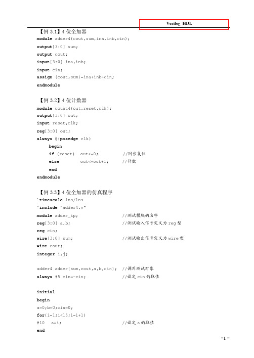
Endmodule【例3.1】4 位全加器module adder4(cout,sum,ina,inb,cin);output[3:0] sum;output cout;input[3:0] ina,inb;input cin;assign {cout,sum}=ina+inb+cin;endmodule【例3.2】4 位计数器module count4(out,reset,clk);output[3:0] out;input reset,clk;reg[3:0] out;always @(posedge clk)beginif (reset) out<=0; //同步复位else out<=out+1; //计数endendmodule09.04.07【例5.11】模为60 的BCD 码加法计数器module count60(qout,cout,data,load,cin,reset,clk); output[7:0] qout;output cout;input[7:0] data;input load,cin,clk,reset;reg[7:0] qout;always @(posedge clk) //clk 上升沿时刻计数beginif (reset) qout<=0; //同步复位else if(load) qout<=data; //同步置数else if(cin)beginif(qout[3:0]==9) //低位是否为9,是则beginqout[3:0]<=0; //回0,并判断高位是否为5if (qout[7:4]==5) qout[7:4]<=0;elseqout[7:4]<=qout[7:4]+1; //高位不为5,则加1endelse //低位不为9,则加1qout[3:0]<=qout[3:0]+1;endendassign cout=((qout==8'h59)&cin)?1:0; //产生进位输出信号endmodule【例9.10】奇偶校验位产生器module parity(even_bit,odd_bit,input_bus);output even_bit,odd_bit;input[7:0] input_bus;assign odd_bit = ^ input_bus; //产生奇校验位assign even_bit = ~odd_bit; //产生偶校验位endmoduleVerilog HDL实例(二)练习二. 简单时序逻辑电路的设计目的:掌握基本时序逻辑电路的实现。
在Verilog HDL中,相对于组合逻辑电路,时序逻辑电路也有规定的表述方式。
在可综合的Verilog HDL 模型,我们通常使用always块和 @(posedge clk)(上升沿)或 @(negedge clk)(下降沿)的结构来表述时序逻辑。
下面是一个1/2分频器的可综合模型。
// half_clk.v:module half_clk(reset,clk_in,clk_out);input clk_in,reset;output clk_out;reg clk_out;always @(posedge clk_in)beginif(!reset) clk_out=0;else clk_out=~clk_out;endendmodule在always块中,被赋值的信号都必须定义为reg型,这是由时序逻辑电路的特点所决定的。
对于reg型数据,如果未对它进行赋值,仿真工具会认为它是不定态。
为了能正确地观察到仿真结果,在可综合风格的模块中我们通常定义一个复位信号reset,当reset为低电平时,对电路中的寄存器进行复位。
测试模块的源代码://------------------- clk_Top.v -----------------------------`timescale 1ns/100ps`define clk_cycle 50module clk_Top.v;reg clk,reset;wire clk_out;always #`clk_cycle clk = ~clk;initialbeginclk = 0;reset = 1;#100 reset = 0;#100 reset = 1;#10000 $stop;endhalf_clk half_clk(.reset(reset),.clk_in(clk),.clk_out(clk_out));endmoduleVerilog HDL实例(三)练习三. 利用条件语句实现较复杂的时序逻辑电路目的:掌握条件语句在Verilog HDL中的使用。
与常用的高级程序语言一样,为了描述较为复杂的时序关系,Verilog HDL提供了条件语句供分支判断时使用。
在可综合风格的Verilog HDL模型中常用的条件语句有if…else和case…endcase两种结构,用法和C程序语言中类似。
两者相较,if…else用于不很复杂的分支关系,实际编写可综合风格的模块、特别是用状态机构成的模块时,更常用的是case…endcase风格的代码。
这一节我们给的是有关if…else 的范例,有关case…endcase结构的代码已后会经常用到。
下面给出的范例也是一个可综合风格的分频器,是将10M的时钟分频为500K的时钟。
基本原理与1/2分频器是一样的,但是需要定义一个计数器,以便准确获得1/20分频模块源代码:// --------------- fdivision.v -----------------------------module fdivision(reset,f10m,f500k);input f10m,reset;output f500k;reg f500k;reg [7:0]j;always @(posedge f10m)if(!RESET) //低电平复位。
beginf500k <= 0;j <= 0;endelsebeginif(j==19) //对计数器进行判断,以确定F500K信号是否反转。
beginj <= 0;f500k <= ~f500k;endelsej <= j+1;endendmodule测试模块源代码://--------------- fdivision_Top.v ------------------------`timescale 1ns/100ps`define clk_cycle 50module division_Top;reg f10m=0,reset;wire f500k;always #`clk_cycle f10m = ~ f10m;initialbeginreset=1;#100 reset=0;#100 reset=1;#10000 $stop;endfdivision fdivision (.reset(reset),.f10m(f10m),.f500k(f500k));endmoduleVerilog HDL实例(四)练习四. 设计时序逻辑时采用阻塞赋值与非阻塞赋值的区别目的:1.明确掌握阻塞赋值与非阻塞赋值的概念和区别;2.了解阻塞赋值的使用情况。
阻塞赋值与非阻塞赋值,在教材中我们已经了解了它们之间在语法上的区别以及综合后所得到的电路结构上的区别。
在always块中,阻塞赋值可以理解为赋值语句是顺序执行的,而非阻塞赋值可以理解为赋值语句是并发执行的。
实际的时序逻辑设计中,一般的情况下非阻塞赋值语句被更多地使用,有时为了在同一周期实现相互关联的操作,也使用了阻塞赋值语句。
(注意:在实现组合逻辑的assign结构中,无一例外地都必须采用阻塞赋值语句。
下例通过分别采用阻塞赋值语句和非阻塞赋值语句的两个看上去非常相似的两个模块blocking.v和non_blocking.v来阐明两者之间的区别。
