CDI系统操作手册
EDI说明书
注意!1.在操作和维护Canpure TM EDI组件时必须始终遵守本使用手册中的有关规定2.必须完全理解本手册内容并经过相关技术培训才能使用Canpure TM EDI组件3.对于不符合本手册要求所造成的损失,制造商不承担任何责任4.Canpure TM EDI组件在使用期间出现异常现象,用户不得自行拆装,应立即通知售后服务商5.我们保留不断改进产品的权利,如有变动恕不另行通知目录目录 (2)第1章EDI技术介绍 (5)1.1 EDI技术本质 (5)1.2 EDI技术是水处理工业的革命 (5)1.3 EDI过程 (5)1.4 EDI的应用领域 (7)第2章组件简介 (8)2.2 EDI的组件结构 (8)2.3 EDI组件优势 (8)第3章运行条件 (9)3.1 运行参数 (9)3.2 运行电流及运行电压 (9)3.2.1 供电 (9)3.2.2 纯水质量与电流的关系 (10)3.2.3 电流与给水水质的关系 (10)3.2.4 稳定运行状态 (11)3.3 给水要求 (11)3.4 给水TEA与电导率 (13)3.5 污染物对除盐效果的影响 (13)3.6 浓水循环系统 (14)3.7 系统加盐系统 (14)3.8 离子性质与运行参数的关系 (15)3.8.1离子大小 (15)3.8.2 离子电荷 (15)3.8.3 离子相对树脂的选择系数 (16)3.8.4 弱带电物质 (16)3.9 温度与运行参数的关系 (16)3.9.1 压力损失与温度的关系 (16)3.9.2 水质与温度的关系 (17)3.9.3 电阻率仪表的温度补偿 (17)3.10 流量与运行参数的关系 (18)23.10.1 压力损失与流量的关系 (18)3.10.2 极水压力损失 (18)3.10.3 浓水压力损失 (18)3.10.4 给水-纯水的压力损失 (18)3.11 纯水对浓水压差对水质和内部泄漏的影响 (19)3.12 优化运行条件 (19)第4章包括EDI的水处理全系统设计 (20)4.1 EDI给水处理 (20)4.1.1 活性碳...............................................................................................................错误!未定义书签。
CDI-S200 串行接口卡用户指南说明书
CDI-S200SERIAL INTERFACE CARDLF Z1F R 230MUSIC MUTEZ NE ZONE 3MIC 1 ACCMUSIC EQMUSIC EQLF HF HFIG AN DIG/AN FR REMFR/REM 0V Z2Z3POWER 40-6 4FURATIN115SERIAL INTERFACE CARDInstallation Guide2CDI-S200 Installation Guide v1.0CDI-S200 Installation Guide v1.03ContentsIntroduction (4)Scope of this manual ...............................................................................4What’s in the box (4)Installation (4)Configuring the CDI-S200 .....................................................................4Baud Rate ..............................................................................................5Handshaking ..........................................................................................5CX263 jumper settings ......................................................................5Mechanical fitting and internal connection ........................................6CX263 switch settings .......................................................................7Partial music function control . (7)CDI-S200 Serial Control (8)Pinout .........................................................................................................8Port parameters .......................................................................................8Abridged command set ......................................................................81. Input selection ................................................................................102. Music Level......................................................................................103. Music Mute/Unmute .....................................................................114. Mute/unmute individual microphones ......................................115. Paging control (11)APPENDIX (12)Cable lengths (12)CDI-S200 Installation Guide v1.04IntroductionThe CDI-S200 is an optional RS-232C interface card designed specifically for use with the Cloud CX263 Zone Mixer. It allows theCX263 to be controlled by third-party systems (such as Crestron, AMX, etc.), using RS-232C serial data.When installed, the CDI-S200 permits the following CX263 functions to be controlled remotely:•Music source selection for each zone •Music level in each zone •Music muting•Muting of individual microphones •Activation of Mic 1’s paging accessPhysically, the CDI-S200 is a small printed circuit board (PCB), which is retrofitted internally in the CX263 such that the 9-pin D-type RS-232C connector is available at the rear panel.Scope of this manualThis manual describes the mechanicalinstallation of the card and the connections that need to be made to it. It also explains the various configuration options that the card offers, and the various jumper and switch settings that need to be made to the CX263 to achieve correct operation.The manual also gives a general overview of the RS-232C serial control protocol used by the CDI-S200, and some examples of the most useful commands. This information should be adequate for most installations, but please note that a full description of the RS-232C protocol is beyond the scope of this manual. The full protocol can be found at .What’s in the box•CDI-S200 PCB•Installation Guide (this document) • 2 qty M3 x 25 mm mounting pillarsInstallationConfiguring the CDI-S200Before installing the CDI-S200 in the CX263, various jumpers on the PCB need to be set correctly. (This step should be performed first because the PCB is installed in the CX263 upside-down, and access to the jumpers is very difficult once it is in position.)The jumpers are concerned with setting the parameters of the serial port (see “Port parameters” on page 8). The port parameters should be set to suit the control system being used. It is quite likely that the factory default settings will provide correct operation; nevertheless, it is important to check that this is so and alter the settings if necessary.T o move the jumpers, use small pliers to gently pull the jumper off the header pins and replace in the correct position. Do not use undue force, and do not use pliers which are too big.There are four jumpers, J1 to J4.CDI-S200 Installation Guide v1.05Baud RateJumpers J1 to J3 set the serial port’s baud rate. The default setting is 9600 baud . Check the baud rate of the controlling equipment. If a different baud rate is required, set the jumpersaccording to the diagram below:J1 J2 J3J1 J2 J3J1 J2 J3HandshakingRS-232C serial communication between equipment sometimes requires flow control (or “handshaking”), to confirm that transmitter (the controller) and receiver (the CDI-S200 in this case) are correctly synchronised. PCB jumper J4 controls handshaking.Handshaking may be via “hardware”,“software”, or off. Hardware handshaking is also referred to as “RTS/CTS”, and needs additional pins of the 9-pin serial connector to be wired (see “Pinout” on page 8).Software handshaking is also referred to as “Xon/Xoff”.The default setting is off (no handshaking); J4 is left attached to the centre pin of the header at the factory. If the controlling equipment requires handshaking, reset the jumper according to the following diagram:CX263 jumper settingsIn order for the CDI-S200 to fully control the CX263, it is necessary to correctly set some jumpers on the CX263 main PCB. These are J4 to J6, and J19 to J24. Because some of these jumpers will be inaccessible once the CDI-S200 PCB is installed, we recommend that they are set before fitting it.Jumpers J4 to J6 are all on 2-pin headers, and can thus be present or absent. See page 6 for a guide to their location. They determine how the CX263’s Mic Input 1 access control operates. When a CDI-S200 PCB is installed, all three jumpers must be absent (we recommend that the jumpers are electrically removed, but left in place on just one pin of the header, in case the unit needs to be reconfigured in the future).T o move the jumpers, use small pliers to gently pull the jumper off the header pins and replace in the correct position. Do not use undue force, and do not use pliers which are too big.Jumpers J19 to J24 determine how music source selection and music level in each zone are controlled remotely. T o allow a CDI-S200 PCB to fully control a CX263, all six jumpers must be in the ‘SW’position. These jumpers are all on the small “daughter-board” at the centre-rear of the CX263 which carries the DIG/AN and FR/REM switches for each zone.It is possible to configure the CX263 so that only certain unit functions are under the control of the CDI-S200. Refer to “CX263 switch settings” on page 7 for more details.CDI-S200 Installation Guide v1.06Mechanical fitting and internal connectionIf retrofitting the CDI-S200 to an existing CX263 installation, turn the CX263 off, remove its IEC mains lead and all other rear panel connections (marking as necessary to assist re-connection). If the CX263 is mounted in a rack, remove it.If fitting the CDI-S200 to a new CX263, unpack the CX263.In either case, place the CX263 on a flat surface, with the rear of the unit facing you.1. Undo the six screws securing the toppanel of the CX263; remove the panel. Retain the screws.2. Remove the blanking plate covering theserial interface module connector hole in the rear panel by removing the two self-tapping screws securing it.3. Identify the empty 16-pin header labelledCON2 on the main PCB behind the empty serial connector hole. Note there is an M3 screw immediately behind this connector, and another about 45 mm to the right. Both these screws are clearly marked with arrows; remove and retain them.CX263 PCB: CDI-S200 MOUNTING LOCATION4. Screw the threaded ends of the two25 mm mounting pillars supplied with the CDI-S200 into the holes vacated by the screws removed in Step 3.5. On the CDI-S200 board, remove the twosmall threaded bushes on the D-type connector; retain them. An M3 nut-driver is the best tool for this. Note that these bushes also retain the metal connector shell – be careful to keep it in place duringthe next two steps.REAR VIEW OF CDI-S200 PCB6. Plug the connector on the end of theribbon cable into connector CON2 on the CX263 main PCB. Note it can only be inserted one way round, with the cable exiting to the left.7. With the CDI-S200 PCB upside-down,insert the D-type connector through the hole in the rear panel. Y ou will see that the two holes at the other end of the PCB are aligned with the mounting pillars fitted in Step 4. Fix the board to the pillars using the screws removed in Step 3.8. Replace the two bushes removed in Step5 adjacent to the D-type connector by screwing them through the rear panel. The two self-tapping screws removed in Step 2 are no longer required.CDI-S200 Installation Guide v1.07CX263 switch settingsAfter the CDI-S200 card has been fitted, and J4 – J6 and J19 – J24 (on the CX263 main PCB) set as described above, the top cover of the CX263 can be replaced, using the original screws.The three blue rear panel switches DIG/AN (adjacent to the RSL-6 connectors) should now be set to DIG – i.e., in their ‘out’ position. The three blue rear panel switches FR/REM (next to them) should be set to REM – i.e. in their ‘in’ position. The CX263 is now ready for full serial remote control.Partial music function controlIt is also possible to configure the CX263 so that the CDI-S200 only controls certain unit functions, leaving others to be manually controlled, either from the front panel or from a Cloud RSL-6 remote control plate. If this is required, set the rear panel switches and the internal jumpers J19 to J24 according to thetable below.* When the CDI-S200 is to control music level, jumpers J19, J21 and J23 may be set in either the DG or SW position. However, they must NOT be removed altogether.CDI-S200 Installation Guide v1.08CDI-S200 Serial Control PinoutThe rear panel serial connector is a female 9-pin Dsub.The pinout is shown in the table:For many installations, it will only be necessary to connect pins 2, 3 and 5. If the controlsystem’s serial port is also a 9-pin D-type, use a D9-to-D9 “straight” cable (i.e., one wired with pin 1 to pin 1, pin 2 to pin 2, etc.) If the control system’s serial port is a screw-terminal (or other type of) connector, the terminals will most likely be marked “Tx”, “Rx” and “Gnd”, or something similar. In this case, connect “Tx” to pin 3 on the CDI-S200, “Rx” to Pin 2 and “Gnd” to pin 5. See the following illustration for details.NOTE: Not all control systems interpret“Tx” and “Rx” the same way, and it may be necessary for a “crossed” cable to be used instead. A crossed cable is one with pin 2 connected to pin 3 at the other end, and vice-versa. If your CDI-S200 appears to ignore control system instructions and all connections, programming, etc., appear satisfactory, try reversing pins 2 and 3 at one end of the serial cable.The installer should also check whether the control system being used requiresRS-232C flow control (or “handshaking”) tobe implemented, and if so, whether hardware control or software control is used. Hardware handshaking (sometimes called RTS/CTS) requires pins 7 and 8 to be connected.CONTROLLERCDI-S 200TX“STRAIGHT” RS-232C SERIAL CABLENote that some installation require a “crossed” cable in thiscase, pins 2 and 3 should be reversed at one end.Abridged command setThe commands listed in the General Format table (page 9) are those most commonly required. For all other commands, data requests and responses, please refer to the CDI-S200’s full RS-232C protocol document at .The table provides the general format of each type of command. The commands are given in ASCII form; note that all characters in the command, including the non-alphanumeric ones, must be sent. The characters shown in italics must be replaced by specific numeric values when a command is sent.Following the table, an example of each command type is given; refer to the general format to see how the variable characters are replaced by specific values. The commands in the examples are given in both ASCII and hex form.CDI-S200 Installation Guide v1.09CDI-S200 Installation Guide v1.010Examples:1. Input selectionT o directly select a specific music source in a particular zone, the value of x in the general format is the number of the Line Input (1 to 6) to be selected, and the value of y is the number of the zone (1 to 3) to which the command applies. Note that x can also be set to zero to positively de-select all music sources in a zone.Alternatively, the music sources in any zone may be “stepped through” one at a time (in either direction), using increment or decrement commands. If an increment command is received when Line In 6 is already set, the command is ignored. If a decrement command is received when Line 1 is set, no music source is selected (equivalent to the “Line 0” command mentioned above). Any further decrement commands are ignored.If wished, all three zones may be set simultaneously to the same music source with a single command; again, the “all-zone” source may also be incremented or decremented as for a single zone. Note that the strings for “all-zone” commands merely omit the three ASCII characters which specify the zone number (Z y.).2. Music LevelThe music level in any zone (where y = 1 to 3) can either be set to an absolute value (in dBs), or increased/decreased by a specified number of dBs. Adjustment can be made in half-dB steps, and the values m , p and q in the General Format table represent the number of half-dB steps.For absolute levels, the value of m corresponds to attenuation rather than gain, thus 0 dB ismaximum level and at -90 dB the music channel is effectively muted. The value of m in the general format is the attenuation level in half-dBs, and may thus have a value of between 0 and 180. Therefore, to set the output level to 10 dB below the maximum level, m must be given a value of 20.T o alter the music level by a specified amount, the ASCII character ‘A’ is replaced by ‘U’ (up) or ‘D’ (down) in the string. The value of p or q in the general format is the level increase in half-dB steps (0 to 180), or the level decrease in half-dB steps (0 to 180) respectively. A command to increase the level by a number of dBs greater than the current attenuation will set the level to maximum. Similarly, a command to decrease the level by a number of dBs greater than (90 minus the current attenuation) will mute the music channel.CDI-S200 Installation Guide v1.011If wished, the music in all three zones may be set to the same level with a single command. Note that the strings for “all-zone” commands merely omit the three ASCII characters which specify the zone number (Z y.).3. Music Mute/UnmuteMusic may be muted or unmuted in any zone by replacing y in the General Format table with 1, 2 or 3. The commands to mute or unmute music in all zones contain no variables, thus those given inthe General Format table are always applicable.4. Mute/unmute individual microphonesThe CX263’s two mic inputs may be muted or unmuted. It is not possible to mute/unmute each mic input individually. There are no variables in the command string and thus those given in theGeneral Format table are always applicable.5. Paging controlPaging via Mic 1 input may be enabled for any combination of the CX263’s three zones by sending a command which includes the two ASCII characters “PA” followed immediately by a further three characters which define which zones are to be paged. The three zone characters represent zones 1, 2 and 3 respectively, and must be either an ASCII “X” (enable paging) or an ASCII “O” (don’tCDI-S200 Installation Guide v1.012enable paging). The following examples illustrate this.Paging may be cancelled – whatever combination of zones has been enabled – with a single “release” command, which contains no variables.Note that it is not possible to enable paging via Mic Input 2 by serial control.APPENDIX Cable lengthsRS-232C serial communication can use either shielded or unshielded cable. The longest cable run that can be practically used for error-free operation in a given installation will depend on several factors: cable type, the baud rate used and the amount and type of electrical noise present in the cable’s vicinity.A realistic figure for maximum cable length is 250 ft. (76 m.) using good-quality shielded cable and 100 ft. (30 m.) using unshielded cable, at 9600 baud (the most common data rate). However, the figure may be higher or lower in a particular installation.Lowering the baud rate will permit significantly longer cable runs to be used.Cloud Electronics Limited 140 Staniforth RoadSheffield S9 3HFEnglandT el: +44 (0)114 244 7051 Fax: +44 (0)114 242 5462 email:*************.ukweb: 。
德力西CDI9000系列变频调速器使用说明书
附录 1: 技术规范 .............. 70 附录 2: 定期维护及检查方法 .... 71 附录 3: RS-485 通讯协议修正.... 72 附录 4: 用于注塑机改造的说明 .. 76 附录 5: 典型接线图 ............ 79
第三章 变频器的安装及运行..... 10
3.1 安装 ..................................................... 10 3.2 卸下和重新装上前盖 ........................... 10 3.3 取下和重新装上数字操作健盘 ............. 10 3.4 选择安装变频器的环境........................ 11 3.5 安装间隙 ............................................. 12 3.6 接线 .................................................... 13 3.6.1 主回路的接线 ................................ 13 3.6.2 外围设备和任选件的接线 .............. 14 3.6.3 接地 .............................................. 18 3.6.4 控制电路的接线............................. 19 3.7 运行 .................................................... 22 3.7.1 操作方式的选择............................. 22 3.7.2 试运行前的检查............................. 23 3.7.3 试运行 ........................................... 23 3.7.4 运行检查 ....................................... 23
德力西变频器说明书CDI9000
CDI9000系列变频调速器使用说明书产品符合标准: GB/T12668.2-2002 / IEC61800.2:1998GB 12668.3-2004 / IEC61800.3:1996 □安装、使用产品前,请仔细阅读使用说明书,并妥善保管、备用。
德力西(杭州)变频器有限公司DELIXI (Hangzhou) Inverter Co., Ltd.目录 目 录第一章序言 (3)1.1安全运行的注意事项 (4)1.2 验收 (5)1.2.1验收检查 (5)1.2.2检查铭牌数据 (5)第二章 产品外形尺寸及规格 (6)2.1 产品外形尺寸 (6)2.2 CDI9000变频器系列规格 (8)第三章 变频器的安装及运行 (10)3.1安装 (10)3.2 卸下和重新装上前盖 (10)3.3 取下和重新装上数字操作健盘 (10)3.4 选择安装变频器的环境 (11)3.5 安装间隙 (12)3.6 接线 (13)3.6.1 主回路的接线 (13)3.6.2 外围设备和任选件的接线 (14)3.6.3 接地 (18)3.6.4 控制电路的接线 (19)3.7 运行 (22)3.7.1 操作方式的选择 (22)3.7.2 试运行前的检查 (23)3.7.3 试运行 (23)3.7.4 运行检查 (23)第四章键盘操作 (24)4.1 键盘按键及功能 (24)4.2 变频器显示方式 (25)4.3 设定数据的步骤 (LED键盘) (26)4.4 运行数据的监视步骤 (LED 键盘) (27)第五章 功能参数说明 (28)5.1 功能参数一览表 (28)5.2 参数设定准备 (36)5.2.1 参数设定 (36)5.2.2 开机显示画面选择(10-02) (36)5.2.3 自设定显示功能选择1(10-03)..375.2.4 自设定显示功能选择2(10-04)..375.2.5 输入端子状态显示(00-12) (37)5.2.6 输出端子状态显示(00-13) (37)5.3基本参数的设定 (38)5.3.1 V/f特性的设定 (38)5.3.2 频率限制(01-07,01-08) (39)5.3.3 使用2种加减速时间 (40)5.3.4 软启动特性(01-37) (41)5.4 运行指令 (41)5.4.1 模拟频率设定方式 (41)5.4.2 载波频率(01-26) (41)5.4.3 反转禁止 (02-21) (42)5.4.4 启动时直流制动时间(01-19) (42)5.4.5 选择停止方式(02-16) (42)5.4.6 滑差补偿增益(01-23) (43)第六章 输入输出功能介绍 (44)6.1 模拟表输出 (44)6.2 多功能输出选择 (44)6.3 频率检测(03-10,03-11) (45)6.4 输入功能介绍 (46)6.4.1 模拟输入 (46)6.4.2 端子运行控制方式(02-17) (47)6.4.3 上电处理端子运行选择(02-19)..486.3.4 复位启动方式选择(02-20) (48)6.4.5 点动频率(01-50) (48)6.4.6 使用多功能输入信号 (49)6.4.7 定时器功能 (50)6.4.8 禁止加减速指令 (50)6.4.9 UP/DOWN(上升/下降)指令 (50)6.4.10 计数器功能 (51)6.5 多段速度和程序运行 (52)6.5.1 多段速度的选择 (52)6.5.2 程序运行 (53)6.5.3 摆频运行 (57)6.6 PI控制参数 (57)6.6.1 外部V2给定值 (03-17,03-18) (57)6.6.2 外部IF反馈值 (03-21,03-22) (58)6.6.3 反馈滤波时间(03-24) (58)6.6.4 PI调节误差极性(05-01) (58)6.6.5 PI调节方式最小运行频率(05-09) (58)6.6.6 PI调节方式最大运行频率(05-10) (58)6.7 保护参数 (59)6.7.1过电压失速保护 (01-29) (59)6.7.2能耗制动选择(06-06) (59)6.7.3自动电压调整AVR(01-16) (59)6.7.4 电流限制(01-27) (60)6.7.5 过转矩检测 (61)6.7.6 电机保护 (62)6.8 其他功能 (63)6.8.1 瞬时停电再启动选择(02-11) (63)6.8.2 追踪启动方式(02-13) (63)6.8.3 跳跃频率 (64)6.8.4 自动转矩补偿(01-14) (64)6.8.5 节能控制(01-30) (64)目 录6.9 用RS-485通信进行控制 (65)6.9.1 通信参数设定: (65)6.9.2 通信规格 (65)第七章 故障 (66)7.1 故障诊断和排除措施 (67)7.2 报警显示和解释 (68)7.3 电动机故障和排除措施 (69)附录1: 技术规范 (70)附录2: 定期维护及检查方法 (71)附录3: RS-485通讯协议修正 (72)附录4: 用于注塑机改造的说明..76附录5: 典型接线图 (79)A5.1. 外部按钮调速接线图 (79)A5.2. 外接电位器调速接线图 (80)A5.3. PID闭环控制接线图 (81)A5.4. 多段速控制接线图 (82)A5.5. RS485通讯接线图 (83)附录6: 选件选用指南 (84)A6.1. 交流电抗器ACL (84)A6.2. 直流电抗器DCL (84)A6.3. 无线电噪声滤波器 (85)A6.4. 远方操作盘 (85)A6.5. 回生制动单元及回生制动电阻 (86)A6.6. 漏电保护器 (86)附录7:变频器知识问答 (87)第一章序言第一章序言感谢您选用德力西(杭州)变频器有限公司生产的CDI9000系列变频调速器。
德力西变频器说明书操作手册-制动单元
NC1 和 NC2 是内部的故障保护触点输出,默认为常闭状 态。当制动单元内部出现过热等故障时,内部触点会自动断开。
第6页
CDI-BR 系列能耗制动单元
2.3 主回路配线规格
配线时必须使用绝缘等级和截面都满足标准的电缆。
第3页
CDI-BR 系列能耗制动单元 峰值电流是指制动单元工作时允许通过的最大电流,该电 流所持续的时间最长不应超过 20 秒。 最小电阻是指制动单元所允许配接的最小制动电阻值。实 际所用的制动电阻必须根据设备的容量和所需的制动力矩进行 选取,且不应小于制动单元最小电阻的值。
1.2 产品技术规格
项目 电源
ACTIVE 制动单元制动时,此灯亮 620~700 电压等级指示
3.3 功能码说明
功能码 P0.00 P0.01 P0.02 P0.03 P0.04 P0.05 P0.06 P0.07 P0.08 P0.09 P0.10 P0.11 P0.12 P0.13 P0.14
名称 电压校正系数 制动开启电压 制动使用率 故障试恢复次数 故障试恢复时间 故障继电器动作选择 故障纪录 1 故障纪录 2 故障纪录 3 故障纪录 4 直流电压值 运行时间(H) 运行时间(M) 运行时间(S) 故障纪录清除
键位 MODE △、▽、>> ENTER STOP
功能说明 切换参数修改方式与当前电压显示状态 选择参数代码。 进入参数修改页面以及确定参数修改 在制动单元报故障后恢复至运行状态
3.2 状态指示区
第8页
CDI-BR 系列能耗制动单元
ACTIVE 700 690 680 670 660 650 640 630 620
化工企业CDI管理标准及管理措施手册(新)
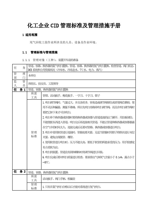
5.吹扫到装置、管道没有固体颗粒时将调节阀进行回装。
6.吹扫完成后要对吹扫质量进行检查,要求排出气体氧气含量小于0.1v%,露点小于-40℃。
任 务2
管道、容器、换热器的氢气吹扫置换
所需
工具
活动扳手、阀门手柄、检漏壶
任 务4
启动氯硅烷液体循环
所需 工具
管钳、梯子、阀门手柄、活动扳手
1.雷雨天气禁止室外作业。
2.检查各静电跨接完好,接地完好。
3.缓缓开启蒸汽阀门,开启疏水阀低点阀门对管道进行暖管。
4.严格控制加热蒸汽量,控制脱吸塔和吸收塔压力差在0.3 MPaG左右。
5.检查各阀门处于正确的位置。
6.启屏蔽泵前确认轴承指针处于绿色区域,检查进料阀门和尾部循环阀门处于开启状态。
10.检查电机功率(电流)是否过载,出现过载情况紧急停机检查,待故障排除后方可重新启动。
11.发现异常情况,应紧急停泵、停蒸汽。
任 务4
启动压缩机
所需 工具
管钳、梯子、阀门手柄、盘车棍
管理 标准
1.雷雨天气禁止室外作业。
2.对压缩机进行氮气置换,置换后的露点≤-40℃,且含氧量<0.1v%。
3.检查各静电跨接完好,接地完好。
7.对各吸附柱分别进行氮气热吹扫置换合格后才能对各吸附柱进行氢气吹扫。
8.在用氢气进行热吹扫前恢复至所有阀门的仪表气。
9.氢气吹扫时吸附柱设置为“自动”,将所有吸附柱按照自动模式进行一次完整的吸附、再生过程,再生尾气根据系统状态送至淋洗塔或再生系统。所有程序完成后,再次测量塔底排气的露点和氧含量,直到氮气含量小于100vppm,露点≤-40℃,且含氧量<0.1 vol%。
装车站操作手册(全)

快速定量装车站操作手册目录第1部分快速定量装车站介绍 (3)1.1系统概述 (3)1.2装车工艺 (3)1.3各子系统描述 (5)1.3.1钢结构 (5)1.3.2机械设备 (6)1.3.3称重系统 (7)1.3.4液压系统 (10)1.3.5配电系统 (10)1.3.6控制系统 (11)第2部分开车和停车顺序 (13)2.1原则 (13)2.2自动装车启动顺序 (14)2.3自动装车停止顺序 (15)2.4紧急停车 (16)第3部分装车运行前、中、后应检查的项目 (16)3.1运行前需检查的项目 (17)3.1.1基本要求 (17)3.1.2主要设备 (17)3.2生产过程中需检查的项目 (18)3.2.1基本要求 (18)3.2,2主要设备 (18)3.2.3停车后需检查的项目 (19)3.2.4 控制室操作人员须知 (19)第4部分常见问题及解决方法A.给煤/料系统 (19)B.装载系统 (20)第5部分计算机软件操作说明 (21)讲解列车编组、调入列车、设备控制、生产查询、报表打印、维护保养等要领第1部分:快速定量装车站介绍1.1系统概述大型快速定量装车站基于大型料斗秤的工作原理,预先在定量仓中按车皮标重装载,通过闸门和卸料溜槽控制,向行进中的车厢快速卸载,实现一次连续动态行进中的快速准确装车。
快速定量装车系统主要由大型钢结构、装车机械设备、称重系统、液压系统、电控系统、软件系统组成。
缓冲仓的目的是存储一定量的煤炭,以确保在正常工作中有足够的煤炭用于装车,从而避免煤炭输送机频繁启动;定量称重装车用于快速准确定量装车;装车机械设备用于控制装车煤流;液压系统为各种机械设备提供动力;电控系统用于装车系统中所有设备监测和自动控制;自动润滑系统为装车机械设备提供润滑,保证设备的使用寿命;软件系统用于判断发出各种控制指令,调节装车精度,监测各设备的运行状态,记录存储装车记录和报警信息。
装车站工作制度同矿井,年工作300天,服务年限同矿井。
cdi使用注意事项
cdi使用注意事项
CDI是一种点火器,在使用CDI时,需要注意以下事项:
- 对于交流点火的CDI点火器,可以在点火线圈的初级加一个熄火开关,对地短路来实现熄火,这种方式对其他配件的影响较小。
- 对于直流点火的CDI点火器,在高压包初级上加熄火开关,容易造成里面元件损坏,可以把熄火开关并联在触发正极,或者串联在点火器电源里边。
- 如果直接断开点火器的12伏电源,可以实现熄火,冲击非常小,但需要厂家对电路进行改进。
在使用CDI点火器时,建议遵循车辆的使用手册,并注意安全操作。
如果遇到任何问题或疑虑,应咨询专业人士。
德力西CDI9200说明书。

CDI标准扭矩校准仪操作教材
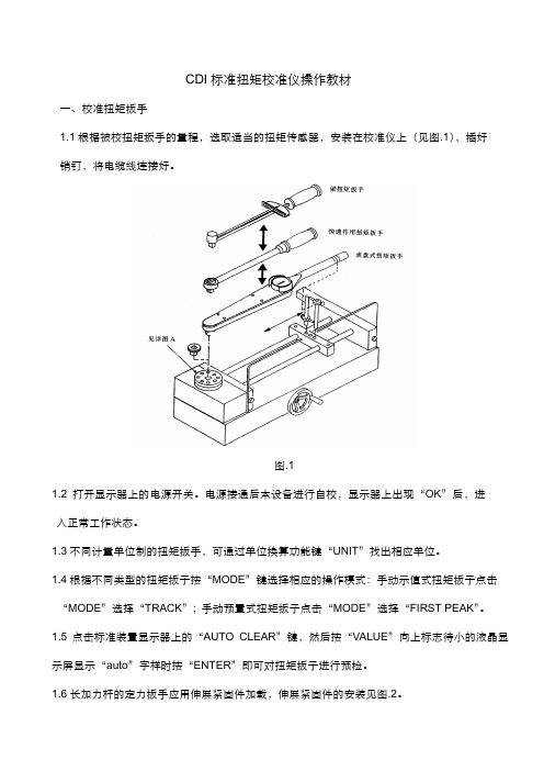
CDI标准扭矩校准仪操作教材一、校准扭矩扳手1.1根据被校扭矩扳手的量程,选取适当的扭矩传感器,安装在校准仪上(见图.1),插好销钉,将电缆线连接好。
图.11.2打开显示器上的电源开关。
电源接通后本设备进行自校,显示器上出现“OK”后,进入正常工作状态。
1.3不同计量单位制的扭矩扳手,可通过单位换算功能键“UNIT”找出相应单位。
1.4根据不同类型的扭矩扳子按“MODE”键选择相应的操作模式:手动示值式扭矩扳子点击“MODE”选择“TRACK”; 手动预臵式扭矩扳子点击“MODE”选择“FIRST PEAK”。
1.5点击标准装臵显示器上的“AUTO CLEAR”键,然后按“VALUE”向上标志待小的液晶显示屏显示“auto”字样时按“ENTER”即可对扭矩扳子进行预检。
1.6长加力杆的定力扳手应用伸展紧固件加载,伸展紧固件的安装见图.2。
1.7在开展大扭矩扳手(200FT·LB以上)校准前,安全屏蔽应已安装牢固、可靠。
1.8将被校扭矩扳手用转接头与传感器作用方体孔相连接,扭矩扳手的手柄与加载装臵立柱相接触,用加载装臵上的调水平机构上下移动,使扭矩扳手处于工作台面平行的位臵。
1.9调好扭矩扳手和校准器显示器上的“零”位,通过加载装臵对扭矩扳手进行预扭。
1.10将数据连接线与电脑连接后打开电脑进入校准软件的主页面,点击“连接”后在出现的窗口中输入用户名“fw”和密码“1111”进行登录。
1.11登录成功后在操作页面中点击“新增”更改记录编号。
更改记录编号时应注意:如果是当月的扭矩扳子则点击“新增”即可,记录编号会自动连续下去;如果是新年新月份的第一把扭矩扳子则点击“新增”后对记录编号的数字进行相对应的修改。
例如2010年1月的第一把扭矩扳子则将记录编号修改为“2010-01-001”。
1.12依次填写“扳手信息”页面中的各类信息。
注:“规格”栏中只须填写扭矩扳子的最大值,不要填写单位。
1.13依次填写“校检设臵”页面中的各类信息。
CDI-2中文操作说明
Chemical Design Inc.PROCESSES • PLANTS • EQUIPMENTPrepared byCHEMICAL DESIGN, INC.285 Market StreetP.O. Box 513Lockport, New York 14095-0513Phone (716) 433-6744 Fax (716) 439-4019 Rev. 0 : September 12, 2007CVD&氢化炉尾气回收装置操作说明目录1.0工艺描述1.1尾气冷凝1.2压缩1.3吸收精馏系统1.4吸附系统1.5设计条件1.6公用工程2.0预开车3.0开车3.1氮气吹扫3.2干燥导热油3.3干燥吸附器3.4循环吸附器3.5干燥物料压缩机3.6用氢气置换氮气3.7定液位3.8启动压缩机3.9循环液体氯硅烷3.10启动制冷系统3.11(HCL解析塔T103的温度剖面图)3.12通物料气4.0停车4.1紧急停车系统4.2短期故障停车4.3长期故障停车4.4正常停车5.0 压缩机维护6.0 安全预防氢气安全操作丙烯安全操作氯化氢安全操作氯硅烷安全操作1.0工艺描述尾气回收单元吸收来自多晶硅还原炉和氢化炉的混合气体并将其分解为液相氯硅烷,液态氯化氢和氢气。
氢气经过HCL吸附塔之后又回到氢化炉。
经过碳吸附器回到CVD还原炉的氢气为高纯氢气,已经去除了杂质(杂质含量<1 vppm)。
剩余物流也被重复用于工艺的其它方面。
CDI负责工艺设计,AS根据P&ID(CDI图纸0622-1A到1J)购买设备并进行安装。
热量及物料平衡见CDI图纸0622-PFD。
1.1 尾气冷凝还原炉尾气经冷却、冷凝以凝缩大部分氯硅烷混合物。
立式壳管换热器利用冷却水逆向冷却气流使温度降低到40℃,然后经气气回冷换热,再经冷冻盐水冷却冷凝。
液体冷凝物被排放到氯硅烷缓冲罐D-101,然后在卧式冷凝器将气体冷冻到-40℃,该冷凝器使用R-22制冷剂。
CDI-1岗位操作规程
天威四川硅业有限责任公司C D I-1尾气回收操作规程编写:李伟校核:沈阳审核:审定:批准:2009年4月初稿目录第一章:CDI系统操作规程 (5)第一节:工作目的 (5)第二节:工作原理 (5)一、三级冷却工作原理: (5)二、吸收和解吸工作原理: (5)三、氢气纯化工作原理: (5)第三节:各种物质性质,技术参数 (6)一、原辅材料质量指标 (6)二、原辅材料消耗 (7)三、产品标准 (7)第四节:基本资源 (7)一、人力资源 (7)二、主要设备(单套) (7)四、调节阀和主要切断阀 (10)五、安全阀 (10)第五节:工艺流程图即简介 (12)一、(流程图见附图一) (12)二、工艺简介 (12)第七节:工艺控制 (20)一、主要控制和调节系统 (20)二:连锁说明 (21)第八节:生产操作规程 (28)一、开车前准备 (28)二:开车操作 (32)三:正常运行操作、寻检、记录 (40)四:(CDI无故障停车) (40)五:停车后工作 (42)六:应急开、停车操作 (42)第九节:常见事故处理 (43)一:泵出现问题 (43)二:冷冻机出现问题 (43)三:瞬间停电 (44)第二章R22冷冻系统岗位操作 (46)第一节:工作目的 (46)第二节:设备工作原理 (46)第三节:CDI回收系统制冷剂R22技术参数 (46)第四节:设备资源 (47)第五节:工艺流程图 (47)第六节:工艺控制指标 (48)第七节:生产操作规程 (48)一:开车前准备 (48)二:开车操作 (48)三:巡检、记录 (49)第八节:常见事故处理 (50)第三章:氢压机操作规程 (52)第一节:工作目的 (52)第二节:工作原理 (52)第三节:工艺控制指标 (52)第四节:操作规程 (52)一:润滑油站的操作 (52)二:水站的操作 (53)三:空负荷试车 (53)四:氢压机氮气试车 (54)五:压缩机一、二级气缸的吹洗 (55)六:氢压机氮气负荷试车 (57)七:氢压机正常开车 (59)八:巡检、记录 (61)九:停车操作 (61)十:注意事项与事故处理 (62)第四章:屏蔽泵操作规程 (64)第一节:工作目的 (64)第二节:工作原理 (64)第三节:开车前检查 (65)一:电动机的旋转方向 (65)二:轴承监视器的检查(机械式) (65)第四节:开车操作 (65)一:启动前的准备 (65)二:启动 (66)第五节:巡检、记录 (67)第六节:停车操作 (67)一:正常停车 (67)二:长期停车 (67)第七节:停车后工作 (68)第八节:注意事项与常见事故处理 (68)第五章:热液泵操作规程 (71)第一节:工作目的及原理 (71)第二节:启动前的准备 (72)第三节:运行 (72)第四节:停机 (73)第六章:废气处理操作规程 (73)第一节:工作目的及原理 (73)第二节:各种物质标准 (74)一:原料质量标准 (74)二:废气处理后的废液 (74)第三节:工艺控制指标 (74)第四节:生产操作规程 (74)一:原始开车准备 (74)四:停车后工作 (75)五:巡检 (75)附一:合成尾气回收安全规程 (76)附二:尾气回收工序救援预案 (77)第一章:CDI系统操作规程第一节:工作目的系统经过三级冷却、压缩、吸收、解吸、氢气纯化这几个过程把SiHCL3合成炉排出的尾气分离为液态氯硅烷、氯化氢气体和氢气。
CDI 灵活扶风说明书

FLEXIBLE FURLER INSTRUCTIONSFF2WARNING: READ BEFORE INSTALLING OR USING FURLER Improper installation of your CDI Flexible Furler or reinstallation of your current headstay may result in the loss of your mast and may cause injury to those onboard.INDEX-Specifications… Page 1-Diagram…Page 2-Parts list…Page 2-Uncoiling instructions…Page 3-Straightening instructions…Page 4-Assembly instructions…Page 5-8 -Sailmaker i nstructions…Page 9-Rigger instructions…Page 9-Notes about Sailing…Page 9-Notes about Trailering…Page 10 -Maintenance and Storage…Page 10 -Warranty…Page 10 SPECIFICATIONS-Max Headstay Length: 29’-Max Wire Size: 3/16”-Max Turnbuckle Pin Size: 5/16”-Headstay: Threaded swaged stud turnbuckle with toggle at the bottom, a toggle at the top isrecommended but any secure fitting like a T-bolt atthe top will work. Must be secured by cotter pins.Navtec turnbuckles are not compatible.-Furling line: 3/16” double braided line or any low-stretch line, twice your boat length. Not included.-Mounting: must not be mounted above theturnbuckle. Link plates can be used for clearance.TOOLS-Hacksaw-Measuring tape-Phillips head screwdriverDiagramPARTS LISTA Halyard Top Fitting 2011B Luff Extrusion/Foil LFF2C Halyard Assembly 1932D Furling Drum/Spool 2010E Shackle (2) 2007F Anchor Pin (2) 1998G Luff Support Pin 2009H Cup 1807I Anti-Rotation Strap 1081J Tack Tension Line 7022-4 - Main Bearing 1033 - Ball Bearing Assembly 1276 - Thrust Washer 1253 UNCOILING INSTRUCTIONSCAUTION: READ BEFORE OPENINGCoiled luffs have a lot of stored energy and can spring open with force when restraining tape is cut. It is recommended to wear face and eye protection. Please refer to instructions below.The sooner you begin the uncoiling and straightening process, the faster and easier it will be to straighten the luff.*The luff should remain coiled for no longer than 2 weeksInstructions for uncoiling the luff:Note: it’s best to have one person cutting the bands with at least one other person holding onto the luff firmly, ensuring it doesn’t spring out1) Stand the luff on its side with the tail at the top2) Have one person stand with one foot on the inside of the luff while holding onto the tail firmly3) The second person should then cut the band of tape near the tail, while the first person is firmly holding onto the tail and gently letting out the luff4) Proceed to cut the next bands one at a time using the same process5) Carefully cut the last band, ensuring everyone is clearSTRAIGHTENING INSTRUCTIONSInstructions for straightening the luff:Note: laying the luff on the ground with weights will not work but will form kinks instead and also void the warranty.1) With approximately one person every 8 feet, recoil the luff in the opposite direction2) Tape the end of the curved side to the straight side3) Lay the luff on the ground for at least 3 hours4) After that time, test to see if it has straightened out5) If not, repeat the same process. Warmer temperatures will help to speed up the straightening6) The luff can have a slight bend to it, the headstay tension will eventually straighten it out ASSEMBLY INSTRUCTIONSAssembly can be done with the mast up but is easiest to do with the mast down.1. Measure the length of your headstay from pin-to-pin with your turnbuckle in its normal setting. If the mast is up, raise a measuring tape attached to the jib halyard to the top of the mast and add the length to the top pin on the headstay.2. With this measurement, deduct 13” and cut the top of the luff using a saw. Do not cut end with the sail-feed slot.Note: In 2017, we updated the FF2 halyard top fittings with a metal sheave to prevent friction when hoisting your sail, this new design requires a deduction of 13” instead of 12.25”.3. Take the halyard top fittingand push the cored end of thehalyard (without the metalferrule) up through the bottomof the off-center hole, not inthe center. Push the halyardover the sheave and out theside of the top fitting.4. Using the de-cored (hollow)end of the halyard with the metal ferrule, pass the ferrule down through the slot at the top of the luff extrusion on the opposite end of the sail feed slot. Trimming the halyard to the correct length will happenonce the entire furler is setup.5. Attach the halyard top fittingto the luff, ensuring that theside with the halyard comingthrough the fitting is on thesame side as the sail feed sloton the bottom of the luff.Tighten the set screw so it firmlypresses against the luff.Note: we updated the line halyards with a metal ferrule instead of the plastic traveller which would become brittle. 6. Using a spare line the length of your luff (not included), tie this messenger line to the de-cored end of the halyard external of the luff, this will beused to raise the sail.7. Unscrew both ends of theturnbuckle completely.8. Pass the swage-end of theheadstay down through thehalyard top fitting and the luff.Using locking pliers, hold the luffabove the threaded pin and screw on the turnbuckle body.9. Using your T-bolt, add additional washers to reduce the clearance between the T-bolt and the bottom of the cup. 10. Add the anti-rotation strap to the T-bolt and washers.11. Place the T-bolt and the anti-rotation strap through the bottom of the cup, then add the bearing (plastic or ball-bearing) to the T-bolt on the inside of the cup.12. Align the holes of the cup with the ant-rotation strap depending on the set-up of your furling line and screw the assembly together.13. Slide the furling drum/spool onto the luff, lining up the sail-feed slot with the anchor shackle. Ensure that the thrust washer stays inside the bottom opening of the spool.14. If mast is up, take the T-bolt assembly and screw into the turnbuckle body, adjust to the correct length. Ensure that all cotter pins are replaced in the turnbuckle.15. Lower the spool/drum over the bearing then raise the luff and insert the luff support pin with the cotter ring into the spool.Note:DO NOT DRILL A HOLE THROUGH THE LUFF EXTRUSION The luff rests on top of the luff support pin, not through it. 16. If mast is down, step the mast and attach headstay. 17. Adjust the backstay to normal tension. If headstay needsadjusting, remove the luff support pin and raise the spool to adjust, afterwards reinserting the luff support pin.18. Use a furling line (not included) to go through the opening in the cup and up through the hole on thetop flange of the spool, tie a knot to secure the line in place.19. Before raising your sail, manually rotate the spool/drum 20 times to load the furling line. If your furling line will be going starboard, wrap the line counter clockwise. If your furling line will be going port side, wrap the line clockwise. Note: the furling line should be low-stretch and no larger than 3/16” twice your boat length and trimmed down if needed. 20. Position the first fairlead or block (not included) so the furling line exits the middle of the cup to avoid any friction. To adjust where the opening of the cup is pointing, repeat step 14 to get the correct alignment.21. Place a cleat (not included) near the cockpit in an easily accessible spot to tie off the furling line.22. To trim the halyard, ensure the messenger line is attached then pull the halyard so the end with the ferrule reaches the top of the forestay at the halyard top fitting.23. For sails that are at or near full hoist, cut the halyard so the head of the sail would be just below the sail feed slot on the extrusion.24. For sails that are not full hoist, estimate the distance between the top of the stay and the head of the sail when it’s raised (A in diagram) and add this to the length of the halyard before cutting 25. Cut the halyard end with scissors and melt the end to prevent fraying.26. Attach the halyard to the head of the sail using either a halyard shackle (not included) or tying a knot directly to it.27. Feed the luff of the sail into the sail-feed slot while hoisting the sail by pulling on the messenger line which is attached to the de-cored end of the halyard (step 6). 28. Remove the messenger line once the sail is fully hoisted and tie off the halyard on the anchor shackle on the spool. Note: Always remember to reattach the messenger line when lowering your sail.29. Tension the sail by tightening the tack tension line to the second shackle on the spool and hoisting the sail tight by pulling on the halyard at a vertical angle, straight down. Note: Using a winch should never be required.30. Furl in the sail by pulling on the furling line and keeping tension on the jib sheet.ASAILMAKER INSTRUCTIONSSails require a #6 luff tape to becompatible with all CDI furlers.Webbing at the head and tack ofthe sail is recommended instead ofmetal grommets for smootherfurling but is not required.A: Overall length of the spool = 9.5”B: Length from the shackle to thetop of the spool = 4”Length of the halyard top fitting = 4”RIGGING INSTRUCTIONSThe CDI flexible furler system cannot be mounted above the turnbuckle as it can cause it to unscrew and dismast. If more clearance is required, it’s recommended to add link plates.The FF2 systems are compatible with 1/4”and 5/16”turnbuckles with a threaded swage-end and a T-bolt toggle.Most Navtec turnbuckles do not work and are not recommended as they’re often too big to fit inside the drum. Cotter pins should be used to lock the turnbuckle, not locknuts as these can unscrew and cause dismasting.Toggles are required at the bottom of the headstay, any secure fitting at the top of the forestay will work but a toggle is also recommended.NOTES ABOUT SAILINGThe tension on the luff doesn’t need to be high and should only be tight enough to removes any creases in the sail, use of a winch usu ally isn’t necessary.When sailing reefed, the jib leads should be moved forward to maintain proper sail shape and avoid the furler from rising off the bearing.To furl your sail, always keep tension on your jib sheet while reefing the furling line. NOTES ABOUT TRAILERINGWhen trailering, strap the furler to the mast in a horizontal position and support the end with the hardware by using a support. ie. 2x4 or PVC tubeKeep the extrusion as straight as possible, do not let either end sag or twist.MAINTENANCEThe only maintenance required is to rinse the furler system including the ball-bearing assembly if applicable, with fresh water 1-2 times per year. Clear out any salt or dirt that may have accumulated.Note: Lubricants are not required but Teflon sprays or dry lubricants are acceptable on the luff if needed.STORING YOUR FURLERStorage is best accomplished by strapping the furler to the mast in a horizontal position and supporting the end with the hardware by using a support ie. 2x4 or PVC tubeWhen storing, avoid making sharp bends in the extrusion. This can become permanent after a period of time and is not covered under warranty.It is not necessary to remove or recoil your extrusion, doing this over long periods of time can become permanent or cause it to break and is not recommended as the furler ages. Avoid exposing the furler in temperatures above 140F/60CWARRANTYThe CDI Flexible Furler comes with a 10-year limited warranty In order for the warranty to be valid, you must be the original owner of the system and have proof of purchase which clearly indicates the date of purchase.If any part becomes non-functional during this time, CDI will repair or replace it free of charge, not including shipping. Note: this warranty does not cover damage incurred from weather, trailering or transporting, collisions at sea, improper storage, improper uncoiling or straightening of the luff including using weights or heat guns, etc.NOTES:21 SOUTH LANDING DR – OAK BLUFF, CANADAP: 844-379-2407 | F: 204-896-6969*******************2022。
2 CDI 图书馆自动化 快速操作流程

演讲完毕,谢谢
并可以自定义颜色。
编目各功能键说明
• “复制”:当需要利用当前画面上书目数据,处理下一个 书目时,执行 此操作,将数据标识区的内容清空。再修改 写入后,成为新数据。
• “返回”:执行此操作退出此著录画面。 • “帮助”:点帮助,可以调出MARC的格式参照文档,对
于不确定的MARC子段,可以打开这个帮助文档进行参考 和查询
订购书目检索界面其它操作说明
• “拷贝书目”:对于已有的书目数据信息,可以查询并显 示出简要信息,选中一条记录后,点击此功能按键,可以 打开当前选择数据的MARC著录界面,可以对当前数据信 息进行修改和调整,然后保存可生成一个新的记录,所以 雷同数据可以用此功能进行处理。
• “修改书目”:对于已有的书目数据信息,如果需要调整 和修改原来的MARC字段信息或编辑馆藏信息,可以先利 用查询功能找出对应的数据后,选择简要显示信息,然后 点击此功能按键,进入编辑修改界面,对数据字段信息进 行调整,最后再“保存”或“总校写入”即可。
追加新读者信息Βιβλιοθήκη 读者状态的改变:• 读者状态的改变: • 挂失:当读者的借书证丢失,执行此功能 • 恢复:当读者的借书证找到了需要对停用的读者恢复其借书证时,执行此功能 • 重登:当某种原因需要对读者进行重新分配读者标识或读者条码,执行此功能 • 停用:当某种原因使读者的借书证暂时停止使用,执行此功能 • 验证:当读者需要做验证处理的时候操作此选项,验证后,有效时间顺延 • 退证:读者在还完图书和交清欠款后,需要做退证处理的时候操作此选项
进行 上架处理,提供给有相应读者级别的读者借阅。
图书的上架
选择上 架的 “馆藏 地点”
进行“上架”处理
图书的流通处理
CDI CD52 非插入式清管指示器 安装和操作说明书

1
如产品文件改动,恕不另行通知, 软件、硬件和固件升级方面版权归CDI所有。软件和固件 版权1999-2007。 文件1999-2007CDI保留所有权利。 文件号码89-09-001 手册修订5.00
注意事项
任何涉及带压在输液或输气的管道上进行作业都具有潜在的危险。所以在使用本 设备时必须按照正确操作步骤施工,以保证安全的工作环境。 任何人在未受到本手册所述所有步骤的培训、或未完全了解在承压输液或输气管 线上进行工作可能产生的危险之前,禁止使用该设备。 该设备的买方对设备的使用方式负责,并对操作人员培训和操作人员工作能力负 责。 无论在任何时候使用该设备遇到任何问题,请立即和CDI联系。
2.0 电源选择
CDI CD52 指示器的电源是两节标准的 1.5VDC 碱性电池。也可以由外接 24VDC 电源供电。 不论是电池或是 24VDC 外接电源都可以连接 SCADA 系统或其它连接。在某些极端的温度 环境下,要求提供 24VDC 外接电源供电。 不同温度时电源的选择 1. -50F 至-22 F (-45C 至-30C):要求安装加热系统,并且使用 24VDC 电源供电。 2. -22F 至-4 F (-30C 至-20C):使用 24VDC 电源供电 3. -4F 至 130 F (-20C 至 54C):电池或 24VDC 电源供电 4 130F 至 176 F (54C 至 80C):使用 24VDC 电源供电
电池模块 显示模块 细节 A
电 池
使用电池时需注意: 1 使用电池时,需要跳转到 P1 键 2 电池安装时,请使用电池安装图 注意:电池模式时,LED 灯不会一直亮
关
6
24VDC
当您使用 24VDC 作为电源时,请参考安装图及用户设置手册 用户设置手册 用户面板
CDI系统操作手册
CDI系统操作手册字体大小:大| 中| 小2006-07-06 21:42 - 阅读:386 - 评论:0采用IP—LXM30X-3的CDI纯水处理系统IP-LX是CDI技术的先锋IONPURE公司开发的最新产品, 2000年投放市场。
IP-LX集合了15年的商业实践,比以前的产品更可靠且成本更低。
本章将介绍相关技术,并将阐述IP-LX与以前原型号产品及竞争伙伴目前同类产品的区别。
CDI指用离子交换膜,离子交换树脂,在直流电场的作用下,从水中去离子的过程,自从1987年Millipore的水处理部,著名的Ionpure(现归属Usfilter公司)将此技术推向市场后,不断进行改进,以降低成本和提高去离子度。
市场上大多数的CDI产品由交替放置的阳离子膜和阴离子膜构成,水从其中的膜隙流过。
这些交替放置的阴、阳离子交换膜被固定在两个带有进出水口的装置之间,水从其中的膜间隙流过。
面向正极的阴离子膜与面向负极的阳离子膜之间构成浓水室,面向负极的阴离子膜与面向正极的阳离子膜之间组成淡水室。
为了便于在弱电解质溶液中强化离子交换过程,在淡水室,有时在浓水室添加离子交换树脂。
在CDI装置机架两端的电极提供了横向的直流电场,直流电场驱动水中的离子运动穿过离子交换膜。
其结果是降低了淡水室中的离子浓度和增加了浓水室的离子浓度。
图1显示的是两个淡水室和一个浓水室离子交换过程。
大型的CDI装置,要由许多这样的基本单元组合在一起,并联工作。
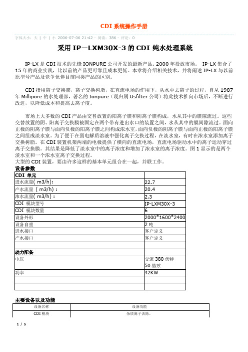
设备参数CDI 单元进水流量( m3/h):22.7产水流量( m3/h) :20.4浓水流量( m3/h) : 2.3CDI 模块型号IP-LXM30X-3CDI 模块数量6设备外形2000*1600*2400设备自重2吨进水接口客户定义产水接口客户定义动力配备电压交流380伏特50赫兹功率42KW主要设备以及功能设备名称设备功能i.计算系统回收率,与设计值比较。
j.缓慢调节直流电源至需要数值。
CDI-1岗位操作规程
内蒙古盾安光伏科技有限公司806尾气回收操作规程编写:赵涛校核:审核:审定:批准:2011年2月初稿目录第一章:CDI系统操作规程 .......................................................................... 错误!未定义书签。
第一节:工作目的................................................................................... 错误!未定义书签。
第二节:工作原理................................................................................... 错误!未定义书签。
一、三级冷却工作原理:............................................................... 错误!未定义书签。
二、吸收和解吸工作原理:........................................................... 错误!未定义书签。
三、氢气纯化工作原理:............................................................... 错误!未定义书签。
第三节:各种物质性质,技术参数....................................................... 错误!未定义书签。
一、原辅材料质量指标........................................................... 错误!未定义书签。
二、原辅材料消耗........................................................................... 错误!未定义书签。
CDI206LX2B操作说明书 Microsoft Word 文档
CDI206LX2操作说明书1.操作箱操作箱上有选择开关(CS-5)和按钮开关(PB-6,7)。
1.1 选择开关(CS-5)进行点动运转和连续运转。
1.2 运转用按钮开关(PB-7绿色)点动运转时,请将选择开关(CS-5)置于点动位置;按动按钮开关(PB-7绿色)期间运转;连续运转时,请将选择开关(CS-5)置于连续位置,按动计数器盒的从零开始按钮(PB-11)或者中途开始按钮(PB-12)之后,按动按钮开关(PB-7)。
另外,如果罩上的联锁用限位开关不动作,就不能进入连续运转。
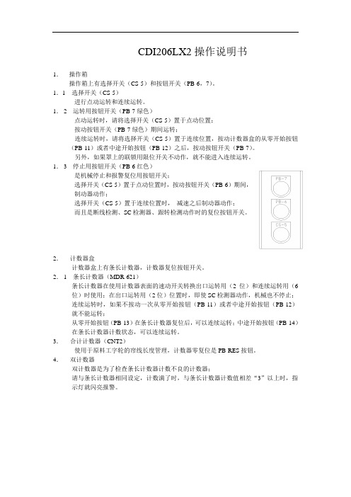
1.3 停止用按钮开关(PB-6红色)是机械停止和报警复位用按钮开关;选择开关(CS-5)置于点动位置时,按动按钮开关(PB-6)期间,制动器动作;选择开关(CS-5)置于连续位置时,减速之后制动器动作;而且是断线检测、SC检测器、跟转检测动作时的复位按钮开关。
2.计数器盒计数器盒上有条长计数器,计数器复位按钮开关。
2.1 条长计数器(MDR-621)条长计数器在使用计数器表面的速动开关转换出口运转用(2位)和连续运转用(6位)时使用;在出口运转用(2位)位置时,即使SC检测器动作,机械也不停止;连续运转时,如果不按动一次从零开始按钮(PB-11)或者中途开始按钮(PB-12)就不能运转;从零开始按钮(PB-13)在条长计数器复位后,可以连续运转;中途开始按钮(PB-14)在条长计数器计数状态,可以连续运转。
3.合计计数器(CNT2)使用于原料工字轮的帘线长度管理,计数器零复位是PB-RES按钮。
4.双计数器双计数器是为了检查条长计数器计数不良的计数器;请与条长计数器相同设定,计数满了时,与条长计数器计数值相差“3”以上时,指示灯就闪亮报警。
5.控制柜控制柜上有指示灯(WL,GL,RL,YL,RL-2)和按钮开关(PB-RES),选择开关(CS-1)。
5.1 白色指示灯(WL)在跟转检测动作时亮灯,请用停止用按钮开关(PB-6)复位;5.2 绿色灯(GL)在机械运转时亮灯;5.3 红色灯(RL)在机械停止时亮灯,另外,由于断线检测动作,停止时闪亮,请用停止用按钮开关(PB-6)复位;5.4 黄色灯(YL)在条长计数器满了时亮灯;5.5 红色指示灯(RL-2)在控制柜内的变频器报警时亮灯,消除原因后,请用复位按钮开关(PB-RES)复位。
CDI检查要点-(第七版)
CDI检查要点-(第七版)序号CDI检查重点1 1.1.21起重机:5年一次12个月一次由合格资质的进行2 1.1.31/34公司ISO9000/14000证书复印件五年有效,年度审核3 1.2.5 货物装载限制的数据4 1.28/29IBC/IAMSAR V01.3 被查看过5 1.2.12医疗急救指南6 1.2.13国际灯塔浮标系统7 1.3.5 有足够的船员(值班一名高级船员,一名普通船员)8 1.3.20/23参加法定培训法定外培训电子海图系统培训9 1.4.5 货物操作期间,天线接地(GMDSS)10 1.4.1无线电备用电源定期记录11 1.4.12自由降落救生艇SART一只放艇内,另一只驾驶台12 2.1.3 操作手册(公司提供)13 2.1.5 操作手册内容(航行、轮机维修货舱、甲板)14 2.1.8 操作手册英文版15 2.1.16船员熟悉船上设备,操作程序及其他适当航行其职责的安排16 2.1.17值班表17 2.1.2随船有一份现时的劳氏保单—救助协议18 2.1.26/27业绩评估19 2.1.28在船预计服务时间20 3.1.1 驾驶台助航仪程序手册21 3.1.5 基本的值班状况22 3.1.17在大洋航行,定位方法超过一个23 3.1.20/23驾驶台程序船长指令中有①值班驾驶员无限制使用航行设备②通信设备③主机24 3.1.37电罗经主分罗经比对每班一次大航向改变后比对25 操舵试验离港航行记录26 操舵转换程序在驾驶台显示27 航海通告、海图更换通知出版后两个月内28 航行灯,报警灯状况良好所有灯架检查29 值班驾驶员熟悉(避碰规则)1.有限能见度2.声号3.白天和夜晚信号4.分道通航制5.直航船和让路船的行动30 浮标系统A,B/侧面标,安全水域标的特征31 引航员的交接船长和驾驶员的交接32 值班驾驶员熟悉:通信设备,舵机转换,主机控制33 驾驶台团队熟悉驾驶台程序指南34 安全系泊/锚泊程序包括9项安全保护措施,安排,避免碰撞相同缆绳的使用,挽桩方法,刹车带测试保养维护35 船岸之间倾斜不能太陡36 至少4人37 蒸汽回收系统(VESS)关闭被批准38 货物操作程序包括:装卸设备操作计量、保管、压载、洗舱39 MSDS 船上所有人都取得40 抑制剂证书内容41 货物监控处理设备操作手册42 装载计算机包括损坏稳性评估弃船批准43 稳性限制是否包括在操作手册44 货物装载限制遵守45 装卸货会议包括所有货物操作人员46 提供可利用的最准的和易读的图管道图和模拟图表47 采取对氮气超压力的防备措施(适当的安全泄压阀合并)48 如有货物泵舱①泵轴温度传感装置,可听视报警器②碳氢气体温测装置,可听视报警器③灯光/通风连锁④消防系统49 5.2.1 船对船驳运操作程序操作总负责人船的兼容性设计通信方式靠离程序软管操作和货物操作程序50 5.2.2 船对船程序符合ICS准则51 5.2.3 船对船期间提供检查清单52 5.2.4 船对船期间操作记录日志内53 5.3.4 浮球修正54 5.3.8 测量系统校正(一年)55 5.3.9 参考的高度永久的标记在舱盖舱口围板上(适用时)56 5.3.14-15便携式温度计良好状态一年校正57 5.3.34船上有舱壁试验工具58 5.3.43-44洗舱化学品标识储存合适(使用时间,用具台帐)59 5.3.41化学添加剂洗舱后进入舱内检查应进行评估(风险)60 5.3.47蒸舱之后测量,惰化并进行评估61 5.3.48公司提供洗舱设备的防护保养指南(包括洗舱软管和电气连接)62 5.3.58船长收到航次指令63 5.5.2 驾驶员应知道:干舱dry 露点温度40℃以下Padding惰化inerting64 5.5.6 高密度货物的影响,最大密度65 5.5.13每个舱的最大装载率66 5.5.15驾驶员熟悉X,Y,Z,OS物质的污染类别和对环境的影响67 5.5.28所有船员都熟悉氮气超压力的危险和应采取的防备措施68 5.5.29船长和大副熟悉船对船的驳运程序其他驾驶员熟悉船对船公司程序69 5.5.3使用循环洗涤水——易产生静电70 5.5.31使用化学剂洗舱——1降低TLV 静电electrostaticgenevators可能危害健康2 易产生静电71 5.5.32蒸舱——易产生静电可燃气体≤1%LFL72 7.1.2 演习分类(消防,防污染,货物抛弃等)73 7.1.9 安全标志告示应张贴于所有危险操作的地方74 7.1.1吸烟规定:餐厅,会议室,走道内75 7.1.13-14甲板照明,应急仓库,物料间和逃生路线的照明76 7.1.1风险评估——高风险的工作577 7.1.16风险评估的形式:许可证,安全会,工作会议记录78 7.1.29驾驶台有直升机操作程序79 7.2.1 甲板部船员使用,应急发电机,应急消防泵80 8.1.11药品清单(字母排列)标的有效期81 8.1.12指定船上负责医疗保健(公司或船长)82 8.1.13药柜包括药品和手术用品83 8.1.24套急救药箱84 8.1.22药物治疗记录最新85 8.1.23解毒剂,有效期,最近货的解毒剂86 8.1.24-25定期身体检查记录间隔87 8.1.33易燃/有毒气体积累的空间检测记录(首甲板,泵舱货控室,主甲板仓库)88 8.1.3公司手册有室外使用电动工具的程序——热5 工许可89 8.1.36公司手册,热工作规定(热工场所,乙炔,氧气分开,消防设备)90 8.1.38公司手册详细设的甲板起重机和其他起重机使用(SWL限制、授权人使用、操作工具的检查、使用手势)91 8.1.53公司程序详细说的值班禁饮时间92 8.1.56公司程序详细说的酒精的分配和消毒程序张贴在公共场所93 8.1.6高级船员培训使用酒精测试设备(1)培训材料(2)培训机构供应商94 8.1.66公司使用程序,处理对人体有害的物质(SHM0300体系文件)(洗涤剂,机舱化学剂)95 8.2.25Manifold区域有栏杆防护(1米高)如用链条或钢丝绳必须绷紧96 9.1.3 防火控制图中类文97 9.1.7 消防员装备30M防火绳灯3H至少斧头非导电98 9.1.15应急消防泵操作须知在附则99 9.1.2消防控制站良好,标明100 9.1.27手提灭火机10年试压或按厂家规定101 9.1.28备用手提灭火机102 9.1.51喷水系统测试记录103 9.1.53易燃液体(样品间的)手提灭火机在外面104 9.2.1 高级船员熟悉固定灭火系统105 10.15-16救生艇筏操作说的显示在艇内或旁,使用IMO符号106 10.1.19救生衣服按顺序状态良好107 10.1.32每一个救生设备的检查和防护记录108 10.1.33每月救生设备检查记载在logbook109 10.2.3所有人熟悉人员落水的程序110 11.1.6公司的程序有使用除油剂111 11.1.有机舱使用洗涤剂的公司程序112 11.1.10有预洗的公司程序113 11.1.12排水监控装置测试/操作记录114 11.1.23有一个书面程序、轮机员请示驾驶员(值班)允许排放舱底水115 11.1.24污水井水的排放(水井,排放设备正常,通向舷外阀锁住,标识)116 11.1.32木塞控制是不适当的117 11.1.34压载水管理计划船级社批注118 11.1.36有压载水交换和处理记录119 11.1.37公司手册有节能政策120 11.1.39船舶有货物冷却加热程序121 11.1.41公司对所有船员节能培训(船上准备1份节能培训材料,每隔季度培训记录)122 11.2.1SMPEP培训,熟悉职责123 11.2.2-5高级船员熟悉X、Y、Z、OS残留的处理程序特殊区域的排放预洗的要求扫舱的要求124 12.3 保安员职责的培训125 12.4 船员知道保安水准显示在船上126 12.7 梯口值班人员不负责货物操作等127 12.10 来客登记登离时间姓名128 12.11 保安培训129 13.9 通风和防火挡板和标记油漆状况、水尺、拖轮推点标记130 14.13 洗手间配件起居室灯光暗或不能操作家具和配件破损贮藏室无整理,有烂食物冰柜温度高,光和报警不工作131 15.1 货舱检查表和压载舱检查表补充2013~2014年CDI检查统计及缺陷汇总未开出缺陷:1、加装燃油事时要有定期监控温度的记录。
- 1、下载文档前请自行甄别文档内容的完整性,平台不提供额外的编辑、内容补充、找答案等附加服务。
- 2、"仅部分预览"的文档,不可在线预览部分如存在完整性等问题,可反馈申请退款(可完整预览的文档不适用该条件!)。
- 3、如文档侵犯您的权益,请联系客服反馈,我们会尽快为您处理(人工客服工作时间:9:00-18:30)。
CDI系统操作手册
字体大小:大| 中| 小2006-07-06 21:42 - 阅读:386 - 评论:0
采用IP—LXM30X-3的CDI纯水处理系统IP-LX是CDI技术的先锋IONPURE公司开发的最新产品, 2000年投放市场。
IP-LX集合了15年的商业实践,比以前的产品更可靠且成本更低。
本章将介绍相关技术,并将阐述IP-LX与以前原型号产品及竞争伙伴目前同类产品的区别。
CDI指用离子交换膜,离子交换树脂,在直流电场的作用下,从水中去离子的过程,自从1987年Millipore的水处理部,著名的Ionpure(现归属Usfilter公司)将此技术推向市场后,不断进行改进,以降低成本和提高去离子度。
市场上大多数的CDI产品由交替放置的阳离子膜和阴离子膜构成,水从其中的膜隙流过。
这些交替放置的阴、阳离子交换膜被固定在两个带有进出水口的装置之间,水从其中的膜间隙流过。
面向正极的阴离子膜与面向负极的阳离子膜之间构成浓水室,面向负极的阴离子膜与面向正极的阳离子膜之间组成淡水室。
为了便于在弱电解质溶液中强化离子交换过程,在淡水室,有时在浓水室添加离子交换树脂。
在CDI装置机架两端的电极提供了横向的直流电场,直流电场驱动水中的离子运动穿过离子交换膜。
其结果是降低了淡水室中的离子浓度和增加了浓水室的离子浓度。
图1显示的是两个淡水室和一个浓水室离子交换过程。
大型的CDI装置,要由许多这样的基本单元组合在一起,并联工作。
设备参数
CDI 单元
进水流量( m3/h):22.7
产水流量( m3/h) :20.4
浓水流量( m3/h) : 2.3
CDI 模块型号IP-LXM30X-3
CDI 模块数量6
设备外形2000*1600*2400
设备自重2吨
进水接口客户定义
产水接口客户定义
动力配备
电压交流380伏特
50赫兹
功率42KW
主要设备以及功能
设备名称设备功能
i.计算系统回收率,与设计值比较。
j.缓慢调节直流电源至需要数值。
注意观察出水水质。
k.记录所有运行数据。
l.测试所有流量限位开关和相关连锁动作。
确保当浓水循环流量不足时,CDI供电模块断电。
m.继续将CDI处于循环状态,直至产水指标达到要求。
n.一旦CDI出水指标达标,将CDI产水阀(至后级水箱)打开,将CDI产水回流阀(至RO水箱)关闭。
再次确认产水压力比浓水排放压力高2-5psig。
o.将系统运行值与设计值比较;
p.在系统运行稳定后(水质和流量),在日常运行数据记录表中记录运行数据。
q.将运行模式选定在自动模式。
在系统运行的第1周,定期检查系统的运行情况以确保系统正常可靠的运行。
运行启动
一旦CDI系统已经启动,然而,实际上,CDI系统不可避免的会或多或少的停机和重启动。
每次的停机和重启动都意味着压力和流量的变化,以及对CDI模块的机械性冲击。
因此,系统的停机和重启动的次数应当尽可能的少,以保证CDI系统的平稳运行。
在系统启动之前和过程中的检查应当作为一种日常工作进行,并且做好工作记录。
仪表的校正,报警,安全设备和管路泄漏性检查也应当作为一种日常工作进行。
停机
1, 关闭CDI模块的供电电源,电压和电流都将自动下降直至零。
2,停运RO产水输送泵。
3, 关闭每个CDI模块的进水阀。
4,关闭CDI模块的隔离阀
系统停机后的再次开机
1, 将CDI系统阀门运行状态处于CDI循环状态;
2,启动RO产水输送泵;
3, 按照CDI启动程序逐项检查,启动CDI系统;
4, 如果有必要,请参见CDI供应商文件对CDI进行杀菌消毒处理;
记录数据
介绍
为了能够更好的跟踪CDI的运行情况,必须收集CDI的运行的相关数据,并记录在日常运行表格中。
除了能够跟踪CDI的运行情况,运行数据对于CDI故障的判断和排除,都非常有价值。
本节是一些推荐的需要记录的运行指标。
CDI 运行数据记录表(样品)。