电机设计软件Speed安装说明
maxwell软件- 调速永磁同步电机
13调速永磁同步电机在用户已经掌握RMxprt 基本使用的前提下,我们将一些过程简化,以便介绍一些更高级的使用。
有关RMxprt 的详细介绍请参考第一部分的章节。
13.1基本原理调速永磁同步电机的转子转速是通过调节输入电压的频率来控制的。
与标准的直流无刷电机不同,这种电机不需要位置传感器。
永磁同步电机的转子上安装永磁体(有内转子与外转子之分),定子上嵌有多相电枢绕组,其极数与转子相同。
永磁同步电机既可用作发电机,也可用作电动机。
当电机工作在电动状态时,定子多相绕组可由正弦交流电源供电或由直流电源经DC/AC 变换来供电。
当电机工作在发电状态时,定子多相绕组为负载提供交流电源。
13.1.1 定子绕组正弦交流电源供电永磁同步电机分析方法与三相凸极同步电机相同,电机既可工作在发电状态也可工作在电动状态,通常采用频域矢量图来分析电机的特性。
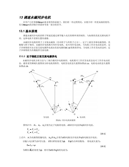
电机发电状态矢量图如图13.1a ,电机电动状态矢量图如图13.1b 。
发电机b. 电动机图13.1 同步电机相量图图13.1中,R 1、X d 、X q 分别为定子电枢的电阻、d 轴同步电抗和q 轴同步电抗。
aq1q ad 1d X X X X X X +=+=(13.1)上式中,X 1为电枢绕组漏电抗,X ad 和X aq 分别为d 轴电枢反应电抗和q 轴电枢反应电抗。
以输入电压U 为参考矢量, I 滞后U 的角度为φ, 称φ为功率因数角, 则电流矢量为:ϕ-∠=I I(13.2)令I 滞后E 0的角度为ψ。
则可得d 轴和q 轴的电流为:⎥⎦⎤⎢⎣⎡=⎥⎦⎤⎢⎣⎡=ψψcos sin I I I q d I (13.3)所以:qd 1I I -=tan ψ (13.4)13.1.1.1 发电机模型在图13.1a ,OM 所代表的矢量可表示为:)j j (aq 11X X R OM +++=I U (13.5)OM 所代表的矢量可用来确定E 0的位置。
令U 滞后E 0的角度为θ,对于发电机称θ为功角,则角度ψ为θϕψ+=(13.6)对于给定的功角θ,我们有;⎥⎦⎤⎢⎣⎡--=⎥⎦⎤⎢⎣⎡⎥⎦⎤⎢⎣⎡-θθsin cos U U E I I X R R X 0q d q 11d (13.7)求得I d 和I q 为:⎥⎦⎤⎢⎣⎡--+-+=⎥⎦⎤⎢⎣⎡θθθθsin )cos (sin )cos (U X U E R U R U E X X X R 1I I d 0110q qd 21q d(17.8)功率角φ:θψϕ-=(13.9)输出电功率:ϕcos UI 3P 2=(13.10)输入机械功率:)(Fe Cua fw 21P P P P P +++= (13.11)式中P fw 、P Cua 、P Fe 分别为风摩损耗、电枢铜损和铁心损耗输入机械转矩:ω11P T =(13.12)ω为同步角速度rad/s13.1.1.2 电动机模型在图13.1, OM 所代表的矢量可表示为:)j j (aq 11X X R OM ++-=I U (13.5’)OM 所代表的矢量可用来确定E 0的位置。
电法工作站软件操作说明--运行和安装(一)

系统安装和运行 软件操作说明中国地质科学院地球物理地球化学勘查研究所2009年4月安装和运行一、软件安装(一)安装要求1. 软件及其附件(1)电法工作站WEM2.5软件光盘;(2)免驱动USB接口加密锁;(3)软件操作说明。
2. 系统要求操作系统:Windows XPCPU:Intel Pentium 处理器内存:64M以上语言支持:简体中文(二)安装与卸载步骤1.安装(1)将本软件配套的光盘插入光盘驱动器;(2)打开光盘驱动器,在“电法工作站WEM2.5”目录中找到安装程序Setup.exe;(3)运行Setup.exe会进入电法工作站WEM2.5软件系统的自动安装过程; (4)请按照提示选择安装选项指导安装结束。
如果您不想改变安装软件的设置,只须按照提示点击“下一步”和“确定”按钮即可。
软件安装完成后,您可在“开始”菜单的“程序组”中找到“电法工作站WEM2.5”软件系统,在该程序组中有本软件系统的所有功能模块程序,但运行这些程序需要与软件配套的软件狗。
2.卸载电法勘探工作站软件提供了自动卸载的功能,使您可以方便地卸载本软件的所有文件、程序组、快捷方式和设置。
方法一:第一步、启动计算机并进入Windows XP;第二步、依次进入“开始/程序/电法勘探工作站(WEM2.5)”,选择“卸载电法勘探工作站”即自动卸载。
方法二:第一步、启动计算机并进入Windows XP;第二步、打开控制面板,双击"添加/删除程序";第三步、在"目前安装的程序"属性页中选中 "电法勘探工作站",然后点击"添加/删除"按钮,即可自动卸载。
二、系统运行电法工作站系统包括常规电阻率/激电法、阵列大地电磁法、可控源音频大地电磁法、磁性源瞬变电磁法和幅相激电法五个方法子系统,各个子系统可以单所示。
独运行,系统主界面如图1-1所对应的图标,即可运行相应的子系统。
CADEX輪組系統使用手冊说明书

4. 定期檢查車輪有無損壞,如果輪圈或其他車輪零件有任何的損壞,例如,輪圈裂痕、輻條斷裂、 培林有鬆脫或間隙產生,在任何情況下不可騎乘. 請洽您的CADEX授權經銷商,以解決此 問題。
5. 每當發生可能造成損壞的意外之後,您必須至CADEX授權經銷商為您檢查您的車輪。 6. 清潔: 。 車輪必須經常以軟質海綿與適當的清潔劑進行清潔。勿使用溶劑,例如丙酮、礦油. 。 花鼓:前後花鼓每年必須至少保養一次。如果經常在極限環境下使用 (例如豪雨、泥濘、雨中騎
1. 組裝CADEX Tubeless System輪組系統時,需搭配輪圈膠帶、無內胎氣嘴、無內胎系統專用
補胎劑及無內胎車胎一起使用.
搭配輪圈式剎車的輪組,推薦使用GIANT耐高溫輪圈膠帶.
2. 安裝輪圈膠帶時,確保膠帶在輪圈中的位置置中,並且在氣嘴孔左右兩側各留15公分的重疊區
域,如圖1所示.
3. 無內胎氣嘴的安裝方式,請參見圖2與圖3.
1. 檢查剎車的相容性,特別是車架、前叉與車輪的剎車介面。依照製造商的安裝步驟安裝剎車與 其零件。
2. 安裝及調整剎車塊時,確保剎車塊位置保持在輪圈上緣往下至少3mm距離,如圖 10所示,否則 將可能導致碳纖層破壞,造成危險並使保固失效.
3. 中央鎖入系統 (Center Lock System) 剎車碟盤的安裝方式請參照圖11。遵照碟剎製造商的指示 安裝碟盤.
maxwell软件- 调速永磁同步电机
13调速永磁同步电机在用户已经掌握RMxprt 基本使用的前提下,我们将一些过程简化,以便介绍一些更高级的使用。
有关RMxprt 的详细介绍请参考第一部分的章节。
13.1基本原理调速永磁同步电机的转子转速是通过调节输入电压的频率来控制的。
与标准的直流无刷电机不同,这种电机不需要位置传感器。
永磁同步电机的转子上安装永磁体(有内转子与外转子之分),定子上嵌有多相电枢绕组,其极数与转子相同。
永磁同步电机既可用作发电机,也可用作电动机。
当电机工作在电动状态时,定子多相绕组可由正弦交流电源供电或由直流电源经DC/AC 变换来供电。
当电机工作在发电状态时,定子多相绕组为负载提供交流电源。
13.1.1 定子绕组正弦交流电源供电永磁同步电机分析方法与三相凸极同步电机相同,电机既可工作在发电状态也可工作在电动状态,通常采用频域矢量图来分析电机的特性。
电机发电状态矢量图如图13.1a ,电机电动状态矢量图如图13.1b 。
发电机b. 电动机图13.1 同步电机相量图图13.1中,R 1、X d 、X q 分别为定子电枢的电阻、d 轴同步电抗和q 轴同步电抗。
aq1q ad 1d X X X X X X +=+=(13.1)上式中,X 1为电枢绕组漏电抗,X ad 和X aq 分别为d 轴电枢反应电抗和q 轴电枢反应电抗。
以输入电压U 为参考矢量, I 滞后U 的角度为φ, 称φ为功率因数角, 则电流矢量为:ϕ-∠=I I(13.2)令I 滞后E 0的角度为ψ。
则可得d 轴和q 轴的电流为:⎥⎦⎤⎢⎣⎡=⎥⎦⎤⎢⎣⎡=ψψcos sin I I I q d I (13.3)所以:qd 1I I -=tan ψ (13.4)13.1.1.1 发电机模型在图13.1a ,OM 所代表的矢量可表示为:)j j (aq 11X X R OM +++=I U (13.5)OM 所代表的矢量可用来确定E 0的位置。
令U 滞后E 0的角度为θ,对于发电机称θ为功角,则角度ψ为θϕψ+=(13.6)对于给定的功角θ,我们有;⎥⎦⎤⎢⎣⎡--=⎥⎦⎤⎢⎣⎡⎥⎦⎤⎢⎣⎡-θθsin cos U U E I I X R R X 0q d q 11d (13.7)求得I d 和I q 为:⎥⎦⎤⎢⎣⎡--+-+=⎥⎦⎤⎢⎣⎡θθθθsin )cos (sin )cos (U X U E R U R U E X X X R 1I I d 0110q qd 21q d(17.8)功率角φ:θψϕ-=(13.9)输出电功率:ϕcos UI 3P 2=(13.10)输入机械功率:)(Fe Cua fw 21P P P P P +++= (13.11)式中P fw 、P Cua 、P Fe 分别为风摩损耗、电枢铜损和铁心损耗输入机械转矩:ω11P T =(13.12)ω为同步角速度rad/s13.1.1.2 电动机模型在图13.1, OM 所代表的矢量可表示为:)j j (aq 11X X R OM ++-=I U (13.5’)OM 所代表的矢量可用来确定E 0的位置。
埃斯顿PRONET用户手册

旋转变压器
针号 K L
★T ★S
H G J
信号 S+ SBAT+ BATPG5V PG0V FG
颜色 蓝色 蓝/黑色 棕色 棕/黑色 红色 黑色 屏蔽
针号 K L T S H G J
★注意:增量式编码器无 BAT+、BAT-信号。
信号 SIN+ SINCOS+ COSR1 R2 FG
颜色 蓝色 黄色 红色 黑色 红/白色 黄/白色 屏蔽
旋转变压器
■ 用途事例
● 贴片机 ● 印刷电路板打孔机 ● 机械手 ● 搬运机械 ● 食品加工机械 ● 纺织机械
■ 型号说明
EMJ – 08 A D A 1 1
ESTUN 伺服电机 EMJ 型
【1+2】 【3】 【4】 【5】 【6】 【7】
【1+2】额定输出功率
记号
规格
02 200W
04 400W
1.74(1.87)
Motor Speed (min-1)
EMJ-02A□A□□
5000
4000
3000
A
B
2000
1000
0 0 0.5 1.0 1.5 2.0
Torque (N·m)
Motor Speed (min-1)
EMJ-04A□A□□
5000
4000
3000
A
B
2000
1000
0 01234
ESTUN 伺服电机
型
■ 特性
● 用于驱动各种机械的进给轴 ● 种类多样(1.0kW~4.0kW、带制动器等) ● 配备 17 位增量式/绝对值编码器,可选配
旋转变压器 ● 标准配置为 IP65
好盈 QuicRun 电调 说明书
声明感谢您购买QUICRUN(酷跑)系列有感无刷电子调速器!无刷动力系统功率强大,错误的使用可能造成人身伤害和设备损坏。
请您在使用设备前仔细阅读本说明书,并严格遵守规定的操作程序。
我们不承担因使用本产品而引起的任何责任,包括但不限于对附带损失或间接损失的赔偿责任;同时,我们不承担因擅自对产品进行修改所引起的任何责任。
我们有权在不经通知的情况下变更产品设计、外观、性能及使用要求。
产品特色↓体积小巧,便于安装于各种车架;↓自动识别有感无刷马达和无感无刷马达,对各种车用无刷马达具有良好的兼容性;↓使用顶级竞赛核心程序,具有一流的操控手感及丰富的调节选项,适应各种比赛场地和环境;↓性价比高,客户无需支付高昂的费用即可拥有一颗稳定可靠、操控性能极好的竞赛级电调;↓8档进角调整功能,显著提升马达输出功率,发挥出马达最大潜能;↓比例式刹车:4段最大刹车力度调节、8段拖刹力度调节、4段初始刹车力度调节;↓9档启动加速度(Punch)调整功能,适应不同特性的车型、轮胎及场地;↓多重保护功能:电池低压保护、过温保护、油门失控保护、堵转保护;↓可使用电调上的SET按键设置和更改电调参数,且有单键恢复出厂默认参数的功能;↓兼容便携式车用电调编程设定卡(显示屏为数码管LED),设定卡具有友好的人机界面,便于在赛场使用。
车用无刷电子调速器产品规格*备注1:此处的马达T数是指在电调0度进角条件下电机T数的极限值,当电调进角加大后马达T数也需要相应增加。
请留意马达及电调的温度,防止过温而造成设备损坏。
首次使用车用无刷电子调速器第一步:根据所使用的电机,按相应的图示接线并复查无误后,进入下一步。
第二步:设定油门行程。
强调:电调第一次使用或遥控器更改过油门“TRIM”微调、D/R、EPA等参数后,均需重设油门行程,不然可能会导致无法使用或误动作。
另外我们强烈建议同时开启遥控器的失控保护功能,将遥控器油门通道的无信号保护(“F/S”)功能设置为关闭输出方式或将保护值设置为中点位置,使得当接收机无法收到遥控器信号后,电机能够停止运转。
派尔高快球 speed安装和使用手册

1. 集成多协议解码器
a. 内置解码器,集成多种协议,最多可集成 16 种通讯协议,通讯波特率可调,通过球机内部
的简单拨码,即可与多种常用系统兼容,通用性极强。
b. RS485 串行控制;球机地址 1~1023。
2. 集成全方位云台
a. 水平 360º无限位连续旋转,其转动速度从 0.2~300rad/s 连续调整;垂直方向转动范围 0~
高速球型一体化摄像机 安装和使用手册
在使用高速球型一体化摄像机之前,敬请您仔细阅读本使用手册
安全提示:
注意
防止触电危险. 请不要打开!
注意:
为了减少触电危险,请勿自行拆卸。里面 没有用户自己可修理的零件。应由有资格 的人员进行维修工作。
在正三角形中闪烁的箭头符号,用以提醒用户在 本产品中附近出现较大的“非绝缘危险电压”, 足以对人体产生危险。
机可以在任意两点间作大于或小于 180 度扫描,扫描速度连续可调。
c. 六组可编程巡视轨迹。每组巡视轨迹包括 16 个预置位,每个预置位的运行速度和滞留时间
分别可调。
d. 轨迹自学习功能。球机能模拟出您在 40 秒内操作的 PTZ 路线,数据断电记忆。
e. 字符叠加功能。人性化的菜单结构设计,使球机的注意号,用以提醒用户参考有关 该机的重要操作与维护的文字说明。
本产品的制造号码标示于底部或侧面。请在下面空白 处填上本机的制造号码,并将此说明书妥善保存,以 便需要时查核。
型号:_________________________ 制造号码:_________________________
的操作方法,否则可能对产品造成损坏。 4. 请不要自行拆卸球机内部器件,以免影响使用,里面没有用户自行维修的零件。
AutoSpeed英文安装说明书

INSTALLATION MANUALThese instructions are designed to help you become familiar with and act as a generic guideline to installing your module. We provide custom instructions, specific to your make and model, upon request. (see below)Installation Steps:Example Pictures3 4Step 1. Make sure your engine is off and no key is in the ignition. Please make sure your vehicle is cool and never hot when working in the engine bay.Step2. Locate your vehicle’s Intake Air Temperature (IAT ) Sensor and /or Integrated Mass Air Flow (MAF ) /IA T sensor.Step3. Locate your vehicle’s two IA T functioning wires. Remember, you are always connecting to the IA T sensor which is only two wires whether or not it is integrated with the MAF. ( If your MAF sensor has5 or 6 wires, the module will only plug into 2 of them.)Step4. Connect your PRO EVOLUTION ECU Performance Module to your vehicle’s IA T sensor using the supplied Wire Taps . Each of your vehicle’s two IA T sensor wires should go into one of the “Through” Holes . Clamp each wire taps to secure the connection.Step5. Mount the module in a cool area away from magnetic surfaces and the engine using the Zip ties provided.You may not feel an immediate increase in performance. Please allow 3-5 driving cycles or up to 300 miles for the module to adapt. Contact us if you do not feel anydifference. We will assist in ensuring the module has been installed and is working properlyTerms and Conditions:+-* Our product does not fix problems with your vehicle. If your vehicle has a knock and or any other issues, it is recommended that you correct the problem before installing. This module is not intended for use on vehicles equipped with nitrous oxide or NOS. Use of this aftermarket product is at your own risk. By using this productyou agree to release us AUTO EVOLUTION, its owners, employees and affiliates from all liability and/or damages you incur by using this product, including, but not limited to: damage, traffic violations, warranty issues and theft. This product has been tested extensively and has been shown to be safe and not harmful to the longevity of the engine. However these are only current test results and not guarantees or implications. All tangible and intangible, physical and intellectual, rights, materials, property and information relevant to any AUTOSPEED product are reserved for the exclusive and sole use of PRO EVOLUTION ECU, , AUTOSPEED , and subsidiary companies. I understand that this manual was provided by a service representative that may or may not be a certified mechanic. PRO EVOLUTION ECU, AUTOSPEED , and subsidiary companies assume no responsibility for the information provided. The information provided is based solely off of the FACTORY SERVICE MANUAL for your vehicle. AUTO EVOLUTION does NOT verify the information prior to release, it is assumed Factory Service Manuals are correct.Frequently Asked QuestionsQ: Why didn’t my manual come with diagrams for my vehicle?A: Due to licensing regulations, we cannot provide diagrams with purchase. We can only providediagrams for support purposes, upon request, Remember, we are using FACTORY diagrams. You can request make and model specific diagrams for no additional cost at http// (See reverse side for details)Q: Does it matter which of the two black wires from the module I hook up to my vehicle’s sensor? A: No it does not. Just make sure you connect to the IAT sensor. Each wire from the module connects toone wire on your vehicle. One module wire will never connect to more than one vehicle sensor wire. Q: Do I have to unplug my vehicle’s battery?A: No. With the many new types of vehicle security systems, unplugging your battery could cause issueswhich can only be solved by the dealership. Q :Do I have to use High Octane Gasoline?A: No you do not, regular grade gasoline is fine. The module will adapt accordingly. We do howeverrecommend 89 and up for maximum performance. Q :What does this module do?A: Our Performance Module works by sending a modified signal through a factory sensor, which islocated in your engine compartment, called the Intake Air T emperature (IAT) sensor. This sensor is linked directly to the Engine Control Module (ECM). The ECM controls fuel timing, fuel injection, pulse widths, and more. The signal sent from your Performance Module alters your ECM reading, making it reprogram itself for a better overall engine tune. The module is 100% safe and never bypasses or exceeds factory specifications / limitations.Q: Is it safe? What about emissions testing and servicing at the dealership?A: Our Performance Modules “piggy back” onto an existing sensor. It is EXTREMEL Y safe to usebecause the ECM has factory safeguards which keep it from going beyond your vehicle’s factory–safe capabilities. This means that it is 100% SAFE for your engine! If you ever decide to sell your vehicle or take it in for servicing, remove our module and the ECM will revert back to its original setting. There are absolutely NO permanent affects, NO footprints, and NO Damage to your engine! Q: The product is not working out for me. What steps do I need to take to return it?A: Please go to and submit a returns request. Please note that modules1 2returned after 15 days will acquire a $15 Restocking Fee and modules returned after 30 days will be exchanged for a new module in accordance with the lifetime guarantee. Q: What is the Lifetime Guarantee?A: The Lifetime guarantee begins after the 30 days trial period for the original vehicle the module waspurchased for. The Lifetime Guarantee is an exchange only program which allows you to send back the original module for a new module free of charge. Please ship the module back along with a note including a reason for the exchange. Once we receive the original module, we will send you a new one within 1-2 weeks.How much does it cost?Performance chip tuning and ECU remaps cost from 200£+V AT. Depending on the work involved remapping your cars ECU chip, the cost for your vehicle may be higher. For a specific quote to chip tune your car ECU, we recommend you contact us directly.How much power will I get?Non turbo petrol engines can achieve up to 10% in power. Turbo petrol engines can achieve up to 15% in power and turbo diesels can achieve up to 30% in power from one of our ECU remaps. But, unless you’re interested in top end speed only, it’s the torque improvements you should be really interested in. Why? Because it’s torque that gives you the acceleration, overtaking ability, push in the back when you put your foot down. To find out more, contact AutoSpeed today. You can call us free from a land line on 08000 515 415.Is ECU remapping safe?Yes it is. AutoSpeed will only remap your ECU software chip within the safe parameters of your engine. Furthermore, we offer a lifetime guarantee on the stability of your ECU chip tune as evidence to how safe we consider our remapping services to be.Will remapping affect my warranty?Chip tuning and ECU remapping will affect your car’s warranty if your car’s warranty excludes any modification to your vehicle during the warranty period. If such a clause does not exist within your car’s warranty then perhaps it might come down to the garage or warranty provider proving that the modification had a direct causal link with the issue at hand that is giving rise to the warranty claim. However, as ECU remapping is not detectible by garage diagnostic systems, whether or not you tell your garage about your ECU remap they will not be aware any modification to your ECU’s software has been made.Doss chip tuning affect reliability?No it does not. When your ECU is remapped professionally, its chip is tuned within the safe parameters of your car’s engine. As a result when your car is tuned by AutoSpeed, the ECU remap will not affect your car’s reliability.Is chip tuning reversible?Yes it is. Though why you would want to revert your car back to its factory map after havingexperienced one of our ECU remaps on your car we could not explain. However, AutoSpeed always retains both a copy of your car’s factory ECU map as well as your car’s chip tuned map. So, if ever your local garage erases your ECU map we will have a back up for you, they won’t but we will! My car is not on your list, can you chip tune it?If you cannot find you car on our list then contact us. Chances are it can be tuned but we may not have yet updated our list. We’d rather you contact us directly to see if your car can be chip tuned reliably than assume your car cannot be remapped. If you are phoning from a land line you can call us free of charge on 08000 515 415Can you remap petrol and diesel cars?Yes we can. Turbo diesels respond best to chip tuning as they can safely gain up to 30% in power and torque. Turbo petrols also response extremely well to ECU remapping and can gain up to 20% in power and torque. Naturally aspirated engines whether they are petrol or diesel do not experience such high power gains but they do benefit from enhanced throttle response and engine smoothness.Do you remap vans and commercial vehicles?Yes we do. AutoSpeed can chip tune cars, bikes, vans and commercial vehicles. The principal behind all of these different forms of transport remains the same. That is, we will remap the software on your vehicle’s ECU via the diagnostic socket [OBD port] where possible and if it is necessary to remove the ECU from your vehicle in order to remap it, then we can provide that service for you as well.RETURNS AND QUESTIONS:PLEASE DO NOT FILE A PAYPAL/CREDIT CARD CLAIM.CALL US AT 800 0415 515 (AM-8:00AM-5:00PM Eastern), AND WE WILL RETURN YOUR CALL WITHIN 24 HOURS. FILING A PAYPAL CLAIM WILL DELAY THE REFUND/SUPPORT PROCESS AS WE NEED TO W AIT FOR THEIR DECISION (USUALLY TAKES 45 DAYS) BEFORE WE CAN ISSUE A REFUND OR OFFER SUPPORT. WE WILL WORK WITH YOU TO RESOLVE ALL ISSUES, INCLUDING RETURNS/REFUNDS. WE ARE A SMALL COMPANY (WHICH GUARANTEES QUALITY HANDMADE PRODUCTS). WE ENJOY WORKING ONE-ON-ONE WITH ALL OF OUR CUSTOMERS, AND WILL RESOLVE ANY ISSUES!You can also email us at a u t o s p e e d .u k @h o t m a i l .c o mThank you for buying from a U.K. Based Company!。
MotorCAD手册

什么是MotorCAD?MotorCAD是用于电机热设计的计算机辅助软件包,采用热路的方法对电机进行热分析和方案优化设计,是全球唯一一款基于热路分析的电机热设计软件。
MotorCAD可以给设计者提供快速的计算方法和精确的计算结果,不仅可以进行参数化计算,而且还能寻找对散热影响最大的变量,可参数化几何结构、物理属性等变量,功能非常强大。
MotorCAD使用方便、简单易懂,即使是非专业人员也可以很快掌握,非常适用于工程实际。
MotorCAD电机库类型:无刷永磁电机、无刷永磁外转子电机、感应电机、开关磁阻电机、直流电机、同步电机、爪极电机、单相感应电机。
MotorCAD的热分析方法目前,电机热设计领域的主要方法包括经验法、数值方法(如FEA、CFD)、热路模型,MotorCAD采用热路计算方法。
经验法经验法一般是基于简单的估算、同比例的放大缩小、测试数据等,其优点是无需计算工具、计算速度快;但是其缺点也十分明显,精算精度差,特别是在设计新型电机的情况下,往往无经验数据可参考,并且经验法无法进行参数化设计,无法知道变量的权重大小。
数值计算方法数值计算法主要包括FEA和CFD两种算法,数值计算方法具有精度高、可参数化计算、后处理强大等特点,但是FEA和CFD软件学习困难、对计算机要求高、计算时间长,参数化计算需要大量的存储空间和很长的计算时间,计算效率低下。
热路计算法目前电机热设计的一个趋势是采用集总热路的计算方法,可对多种电机的稳态和瞬态热分布进行计算,最新的MotorCAD具有优秀的人机交互界面,操作简单,易于掌握,是电机热设计非常有效的工具。
第一章软件界面MotorCAD 提供8中电机类型,永磁无刷电机、感应电机、开关磁阻电机、无刷永磁外转子电机、永磁电机、同步电机、爪极电机、单相感应电机等。
图1.1 电机类型选择图1.2 操作界面软件界面主要包括工具栏菜单及操作界面,操作界面如图1.2红线部分所示,包括几何设置、绕组设置、数据输入、温度计算、数据输出、瞬态计算、热路编辑、参数化计算和脚本编辑等。
farwide AC_系列驱动器用户手册说明书

版本:V21C1.关于手册和AC_系列产品的特点介绍恭喜并感谢您选择使用本系列驱动器所提供的业界一流的电机驱动控制!本手册将为您提供有关驱动器的安装、调试和操作的必要信息,适用于对驱动器进行设计、安装、调试、使用和维护的工程技术人员。
本手册中包含驱动器的快速启动指南、基本技术参数、机械与电气安装、配线、驱动控制参数、典型行业应用宏设置、保养与维护等内容,及其相关操作方法与注意事项。
为了确保您能够正确使用本系列驱动器,充分发挥产品的卓越性能并确保使用者和设备的安全,在开始对驱动器进行操作之前请您务必详细认真地阅读本手册。
同时,读者应该具备电气、布线、电气元件和电气原理图符号等基础知识。
请您注意:不正确的使用可能会造成驱动器运行异常、发生故障,甚至发生设备损坏、人身伤亡等事故!本手册为随机发送的附件,请妥善保管,驱动器若装在机械或传动设备中,请确保本手册能随成套机机设备交到最终用户手中,以便其在驱动器运行过程中随时可获得产品相关特性与信息。
由于我们始终致力于取得产品和相关资料的不断进步与完善,因此,本公司提供的资料如有变动,恕不另行通知。
最新变动和更多内容,请您直接联系我司当地代表处,或访问我们的网站,或微信公众号(二维码位于本手册的封面)。
为让您快速了解并最大化发挥驱动器优势,现将其性能、功能方面的主要特色点介绍如下:◎1.在带有突破性的直接转矩控制技术的支撑下,在全调速范围内的转矩响应、转矩精度等方面具有比肩行业标杆的出色表现,这一特性特别有助于包含异步、同步电机等各类开环驱动控制的应用中提高系统的可靠性、或节省编码器和减速机投资、或降低维护难度与成本。
◎2.出于对节能减排和用户能源成本节省的响应和追求,在电机驱动与控制、电力电子能量变换技术的探索中,实现了将单位能源有效利用率方面推到更高的发展水平,从而使其具有更好的节能节电效果。
尤其是在驱动高效异步电机、永磁同步电机、同步磁阻电机等新型电机的节能应用中。
OLI SPEED 电主轴说明书

OLI SPEED 电主轴说明书电主轴使用说明电主轴是一种高速高刚度精密的电动机,其由精密滚动轴承支承,油脂润滑,外循环水冷却,雕刻(铣)主轴一般为立式使用,使用的方法正确与否将直接影响雕刻和雕铣质量,以及主轴的工作寿命。
1、避免撞击强烈撞击,特别是主轴端部及前端盖部位绝不许撞击,否则会损坏精密轴承及主轴精度,造成主轴回转精度的丧失。
2、正确安装和夹紧安装前应确认主轴电机状态正常,主要指外观无损伤,主轴转动轻匀。
用500V摇表查定子之对地绝缘电阻在100мΩ以上。
主轴电机套筒外径与夹持座孔间的配合公差必须保证主轴电机之套筒能顺利滑入座孔,在任何情况下都不能使用锤子或其他工具来使主轴定位,夹紧力不宜过大,否则会造成精密轴承的钢球滚道变形,使主轴精度及寿命受到影响。
夹持后要检查主轴前端锥孔定心面的跳动应不大于0。
005MM,主轴回转轻匀。
3、筒夹(ER型)压帽和刀具的安装刀具的安装必须保证回转精度,否则会产生剧烈振动,影响雕刻(铣)质量和效率及轴承寿命。
必须十分小心的地擦净筒夹,压帽和刀具以及主轴前端之锥孔,装拆刀具应避免用力过猛。
组装后要查看刀具根部跳动﹤0。
015MM若超差要通过反复放松和拧紧并调整变换刀具柄接触面来纠正,若无改善要检查各接触面是否处于正常状态,切忌乱敲打。
4、启动前必须1)确认主轴套筒所须的循环冷却水已开通,冷却水的温度一般不要超过35°c,但也不宜过低,不宜直接接用自来水,因水温过低会造成主轴电机内部热空气遇冷而形成凝水影响绝缘和轴承生锈,冷却水流量一般可在3-5L、MIN,冷却水应干净无杂屑以防堵塞通道。
冷却水箱中水量约50L—100L,建议水泵用AB-25或AB-50。
进出水口不能相距太近,必须使水在箱内有一冷却过程,力求使进出口水温差能达到2—3°c,要避免造成热水循环而达不到冷却效果。
2)确认电源电压,频率与主轴匹配关系正确,按主轴名牌数据或产品检测报告中提供的电压与频率对应关系设置变频器的U、F 曲线,主轴插头座的1号芯接地,2、3、4号芯接变频器的UVW。
Speed2000中文手册
Speed2000中文手册SIGRITY SpeedXP 实用手册参考SIGRITY SpeedXP 手册(Speed 2000 )2003-02-14SIGRITY SpeedXP 实用手册参考Speed 2000 程序界面概览。
本节只将工具条的内容加以简单介绍,其余部分或者通过例题、或者通过对程序的使用,一般均可掌握。
2.1 主工具条2.2 对象(object)工具条2.3 检查工具条iSIGRITY SpeedXP 实用手册参考2.4 选择工具条2.5 电路工具条2.5 形状工具条(当 Plane 层激活且选中时,可以看到操作过程)2.63D 工具条iiSIGRITY SpeedXP 实用手册参考Speed 2000 手册简介: 1. 使用 Speed200 可以解决的一些问题 ? ? ? ? ? ? ? ? 计算电源、地线噪声对系统电源层、地线层的进行评估、设计,包括其排列以及过孔/管脚的定义鉴定 Package 的谐振评估不同 Package 中间的电磁耦合评估不同位置上的的信号以及噪声波形评估不同位置上的的信号以及噪声的频谱根据不同端口之间的输入阻抗、S 参数、转移特性,确定元器件封装的、基于频率的端口特性评估印制板电路以及 Package 的电磁辐射2. 使用 Speed200 程序框图注意:在 SPEED 2000 中术语“Package”,可以是一个 IC 的封装,也可以是指印刷电路板。
任何不是属于电路元件的东西都认为是Package。
1SIGRITY SpeedXP 实用手册参考第一章本章试图通过一个例子的分析、操作使用户对Speed 2000 的使用、性能有一个较为直观的理解。
建议用户首先根据此例一步步的进行操作,从中领会、理解、掌握Speed 2000 的性能以及使用方法。
SPEED2000 主要包含两个模块:使用 SPDSIM 模块,可以进行模型的仿真;使用 SPDGEN 模块,可以建立包含封装以及电路信息的模型,这个模型的文件是以 .spd 为后缀的文件。
maxwell软件--快速入门
2 快速入门本章将简要介绍RMxprt的软件环境及操作流程。
2.1 Maxwell界面介绍Maxwell v12中集成了Ansoft Maxwell系列软件中的Maxwell 2D,Maxwell 3D及RMxprt。
其中Maxwell 2D和Maxwell 3D是用于有限元(FEM)分析的交互式软件包,能够进行二维和三维电磁场的仿真分析。
由于Maxwell和RMxprt集成在一个界面中,用户可以直接从RMxprt来建立Maxwell 2D/3D模型,大大简化了设计过程中的一些繁琐复杂的工作。
2.1.1 启动Maxwell同所有的Windows程序一样,Maxwell可以从开始菜单或Windows的快捷方式启动。
开始菜单及桌面上的快捷方式在安装Maxwell时就已经自动创建。
在默认条件下,Maxwell安装在Ansoft\Maxwell 12。
下面是启动Maxwell的两种方法。
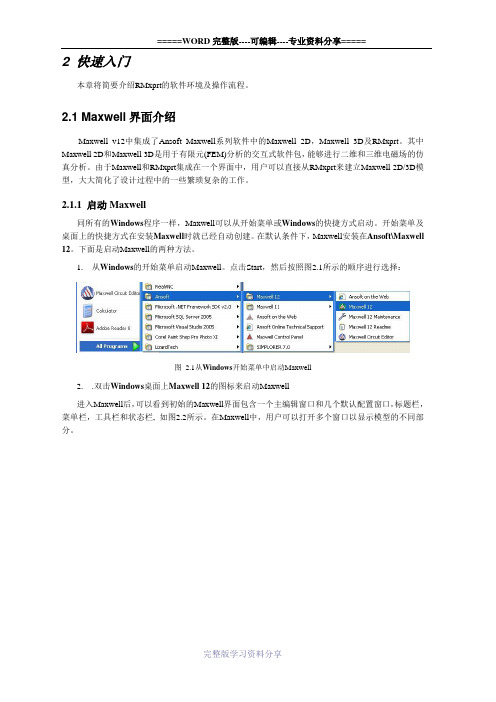
1.从Windows的开始菜单启动Maxwell。
点击Start,然后按照图2.1所示的顺序进行选择:图 2.1从Windows开始菜单中启动Maxwell2..双击Windows桌面上Maxwell 12的图标来启动Maxwell进入Maxwell后,可以看到初始的Maxwell界面包含一个主编辑窗口和几个默认配置窗口,标题栏,菜单栏,工具栏和状态栏, 如图2.2所示。
在Maxwell中,用户可以打开多个窗口以显示模型的不同部分。
图 2.2 Maxwell界面2.1.2 退出Maxwell像所有的Windows程序一样,有很多种途径来退出Maxwell界面。
1.通过菜单栏的File>Exit命令来退出Maxwell, 如图2.3所示。
也可以通过快捷键Alt+F, X。
图 2.3 通过菜单栏命令退出Maxwell2.通过标题栏命令Close来退出Maxwell(在标题栏的Maxwell图标上单击鼠标左键), 如图2.4所示。
E32D Series (Two Speed Fan) 产品说明书

Exploded Parts Listings 9Outer AssemblyPart No. Description 1 M 234224 SIDE COVER LH 2 M 233583 TOP PANEL 3 M 233585 SIDE COVER RH 4M 232379ADJUSTABLE LEG 3” / 76mm5M 232380FOOT O-RING6 M234583DOOR ASSEMBLY (COMPLETE)*RPL D D D D C C*Recommended Parts Level RPL Number of Units In-Service. A+B 5-10 A+B+C10-50A 1-5 A+B+C+D 50+9 Exploded Parts Listings22b22c22d 22e22f22jUp to Ser. No. 744429.From Ser. No. 744430.Elements / Motor / Door Switch22a22a22b22c22d22f22g22h22i22k22l22mExploded Parts Listings 97 M 236214 LAMP HOLDER (Bulb Included). B 8 M 231814 LAMP G9/25W 230V HALOGEN . A 9 M 021354 GASKET . A 10 M 021352 GLASS LENS . A 11 M 021353 SUPPORT FRAME . A 12 M 010761 GROMMET 1½” RUBBER D 13 M 236107K OVEN ELEMENT KIT 6300W 240VB M 236108K OVEN ELEMENT KIT 6300W 220VB —- M 236264 ELEMENT GASKET (not shown) B 14 M 234138 FAN D220 x H50 (For 50Hz)C ---- M 235420 FAN PULLER / TIGHTENER (not shown) C 15 M 235610 MOTOR SHAFT SEAL B 16 M 237342 MOTOR MOUNTING PLATE, E32 B 17 M 237482 SPACER D12-6.5x3D 18 M 237335 FAN MOTOR L7- EB50 2/4 pole 2 speedC 19 M 236053 MOTOR CAPACITOR 6.3uF 60HZ ONLY (Up to Ser No. 744429)B M 236054 MOTOR CAPACITOR 8uF 50HZ ONLY (Up to Ser No. 744429)B M 234252 CAPACITOR 10uF QC (From Ser No. 744430)B 20 M 234875 CAPACITOR 3uF DOUBLE QC M8 STUD (From Ser No. 744430) B 21 M 234821 OVERTEMP THERMOSTAT 355°C / 670°F A 22 ------ MICROSWITCH ASSY -- 22a M 232911 Microswitch Bracket D 22b M 017929 Damper Rod Clip D 22c M 003397 Spacer Plated D 22d M 235354 Microswitch Return Spring E32 C 22e M 041043 Screw M5 x 12 Taptite PHIL D 22f M 024802 Door Microswitch A 22g M 236886 Microswitch Rod (From Ser No. 744430) D 22h M 236885 Microswitch Button Gasket D 22i M 236880 Microswitch Button Assy D 22j M 234403 Microswitch Rod (Up to Ser No. 744429) D 22k M 021637 Microswitch Button D 22l M 013610Pivot Bush D 22m M 021638Pin Circlip D 23 M 232666 OVEN SEAL D 24 M 234802 FUSE HOLDER 16A 250V (not Korea) D --- M 234803 FUSE 10A (not Korea) (not shown) A 25 M 234460 COOLING FAN 92x92x25 230V 50/60Hz BM 234625 FAN D200 x H50 (For 60Hz)C *Recommended Parts Level RPL Number of Units In-Service. A+B 5-10 A+B+C10-50A 1-5 A+B+C+D 50+Elements / Motor / Door Switch - Parts ListM235355 Kit contains 22a,c,d & e9 Exploded Parts ListingsOven RacksItem Part No. Description *RPL 30M 233649 OVEN RACKD 31 M 234658 SIDE RACK LH 5 TRAY D --- M 234656 SIDE RACK LH 4 TRAY D32M233552THUMBSCREWD 33 M 236546 SIDE RACK RH 5 TRAY D --- M 234657 SIDE RACK RH 4 TRAY D --- M 235260 SIDE RACK LH 5 TRAY GN D --- M 235263 SIDE RACK RH 5 TRAY GN D Not ShownM 235262 FAN BAFFLE FOR GN RACKSD--- M 234660 SIDE RACK LH 3 TRAY D --- M 234663 SIDE RACK RH 3 TRAYD *Recommended Parts Level RPL Number of Units In-Service. A+B 5-10 A+B+C10-50A 1-5 A+B+C+D 50+Exploded Parts Listings 9Description *RPL34 M021057SPRAYNOZZLE C35 M234774WATERTUBE D36 M013215NUTBRASS D37 M020869FEMALECONNECTOR D38 M020851WATERSOLENOID ANot Shown M025922 ADAPTOR BRASS ¾” BSP. (USA / CANADA ONLY) D M021527 WASHER RUBBER. (USA / CANADA ONLY) A39 M026160TERMINALBLOCK D40 M026161CABLECLAMP D41 M019213 SNAP BUSH Ø31.5 D42 M022997 DOME PLUG 32mm D43 M231738 CONTACTOR 25A 3P+1NO 230V50/60 B44 M231742CONTACTOR MINI 3P+1NC, 230V (Up to Ser. No.759468 Only) B45 M234429 TRANSFORMER 208/240V x 12VAC SEC 20VA B*Recommended Parts LevelRPL Number of Units In-Service.A+B 5-10A+B+C 10-50A 1-5A+B+C+D 50+Gear Plate / Water Connection Components40399 Exploded Parts Listings*Recommended Parts Level RPLNumber of Units In-Service. A+B 5-10 A+B+C10-50A 1-5 A+B+C+D 50+ItemPart No.Description*RPL 45 M 235275 DOOR OUTER GLASS ASSEMBLYC 46M234930DOOR HINGE ASSEMBLY KIT - which includes:- B47 M 234725 DOOR CATCH BLANKING PLATE C 48 M 041045 SCREW 8 x ⅜" TRUSS HD PHL NP D 49 M 234779 INNER GLASS RETAINING CLIP C 50 M 234757 DOOR INNER GLASS ASSY C 51 M 234767 INNER GLASS PIVOT SPACERD 53 M 235105 DOOR STRIKE ESCUTCHEON WASHER C 54 M 235104 DOOR STRIKE PIN ESCUTCHEON C 55 M 235278 STRIKE LOCKING NUTC 56 M 235277 DOOR ROLLER CATCH STRIKE PIN C 57 M 234580 DOOR ROLLER CATCHC 58 M 234818 INNER GLASS LATCHING BUSHD 59 M 234835 DOME PLUG D 60M 234581DOOR HANDLE WADDoor Hinge Assy Bottom Door Hinge Assy Top--- M 234752HINGE PIVOT KIT - which includes the following:- Door Hinge Pivot Pin Washer M8 Nord-Lock T316 Door Hinge Pivot Bush46Door AssemblyDOOR HINGE ASSEMBLY KIT - 234930HINGE PIVOT KIT - 234752Exploded Parts Listings 9 ControllerItem Part No. Description *RPL61 M235790 CONTROL PANEL LAMINATED E32D (up to Ser. No. 759468) D M237445 CONTROL PANEL LAMINATED E32D/E33D (from Ser. No. 759469) D62 M236256 DIGITAL CONTROLLER KIT B63 M237447 TEMP PROBE PT1000 31D/32D/33D B64 M236885TEMPPROBEGASKET B 65 M234450ENCODERMOMENTARY B66 M235846PAN EL SOCKET CO R E TE MP - D SE R IES C67 M236192DOMEPLUG15.9 D68 M228132 TUBE CLIP #5 D69 M233865BADGEMOFFAT D70 M234447 KNOB TURBOFAN INDEX D71 M041425 SCREW M4 X 6 PAN HD PHIL NP D72 M236060CORE TEMP PROBE KIT (which includes:-) B73 M235845 CORE TEMP PROBE (PT1000) B74 M235847 DUST CAPE CORE TEMP SOCKET D75 M236486 CORE TEMP PROBE HOLDER CM748019 SCREW M4 x 10 TAPTITE PAN POZI ZP D*Recommended Parts LevelRPL Number of Units In-Service.A+B 5-10A+B+C 10-50A 1-5A+B+C+D 50+72Not Shown10 AccessoriesSK StandsSK32 — Stand for E32.735mm/29”(W) x 650mm / 25½”(D) x 900mm/35½”(H). Accepts US Half and US Full Pan.DSK Double Stacking KitVent Tube - Part No. 235299.Base Stand - fitted with CastorsSpacer Frame - Part No. 235037.Base Stand - fitted with Adjustable Feet。
固定速度交流电机操作与安装指南:0-1

851-125 Rev. DTable of Contents. . . . . . . . . . . . . . . . . . . . . . . . . . . . . . . . . . . . . . . .1.0Safety Considerations3. . . . . . . . . . . . . . . . . . . . . . . . . . . . . . . . . . . . . . . . . . .1.1Grounding3. . . . . . . . . . . . . . . . . . . . . . . . . . . . . . . . . . . . . . . . . . . . . . .1.2Fusing3. . . . . . . . . . . . . . . . . . . . . . . . . . . . .1.3Power Wiring to Controller3. . . . . . . . . . . . . . . . . . . . . . . . . . . . . . . . . . . . . . . . . . . . . . . . .2.0Introduction3. . . . . . . . . . . . . . . . . . . . . . . . . . . . . . . . . . . . . . . . . .3.0Product Description3. . . . . . . . . . . . . . . . . . . . . . . . . . . . . . . . . . . . . . . .4.0Product Specifications4. . . . . . . . . . . . . . . . . . . . . . . . . . . . . . .5.0Conveyor Controller Installation55.1Inspecting the Controller5. . . . . . . . . . . . . . . . . . . . . . . . . . . . . . .. . . . . . . . . . . . . . . . . . . . . . . . . . . . . . . .5.2Mounting the Controller5. . . . . . . . . . . . . . . . . . . . . . . .5.3Power Connections to Controller6. . . . . . . . . . . . . . . . . . .5.4Motor Overload Setting and Checking6. . . . . . . . . . . . . . . . . . . . . . . . . . . .5.5Controller Power-up Testing6. . . . . . . . . . . . . . .5.6Motor Connections to Conveyor Controller65.7Motor and Conveyor Controller Power-up Testing6. . . . . . . . .. . . . . . . . . . . . . . . . . . . .6.0Implementing Conveyor Control Applications7. . . . . . . . . . . . . . . . . . . . . . . . . . . . .7.0Operating the Conveyor Controller97.1Starting the Controller9. . . . . . . . . . . . . . . . . . . . . . . . . . . . . . . . .. . . . . . . . . . . . . . . . . . . . . . . . . . . . . . . .7.2Stopping the Controller9. . . . . . . . . . . . . . . . . . . . . . . . . . . . . . . . . . . . . .7.3Controller Reset9. . . . . . . . . . . . . . . . . . . . . . . . . . . . . . . . . . . . . . . . . . . .8.0Troubleshooting10. . . . . . . . . . . . . . . . . . . . . . . . . . . . . . . . . . . . . .9.0Replacement Parts List11851-125 Rev. D2PD0996PD09973851-125 Rev. D1.0Safety Considerations1.1Grounding1.2Fusing1.3Power Wiring to ControllerThis manual contains the information needed to install,operate, and troubleshoot the Dorner impac 100 Conveyor Controller. It is organized in a step-by-step fashion so that the Conveyor Controller may be safely set-up, in the shortest possible time.3.0Product DescriptionThe impac 100 Conveyor Controller is a low-cost Industrial Multi-Purpose Application Controller that can be used to control a Conveyor motor on/off operation as well as vary the speed of the motor. The Conveyor Controller is user-installable with control options that allow it to meet the needs of a wide range of Conveyor control applications (indexing, jogging, accumulation,variable speed, automatic end-stop, emergency-stop,clutch-brake, merging of Conveyors, linking multiple Conveyors,...etc.). The Conveyor Controller can be ordered for Conveyors with fixed or variable speed AC or DC motors.The impac 100 Conveyor Controller’s motor control circuit is designed to support electrical interconnections to a variety of accessory kits (photo-eyes, E-stops, jog buttons, foot switches, E-stop pull cord units, process machine/PLC/PC dry contact interface, and more). Each kit includes brackets for mounting the unit to a Dorner 2100/3100 conveyor,cabling to wire the unit to an impac 100 Conveyor Controller,and instructions for mounting/wiring/operating the unit. The kits are connected to the impac 100 Conveyor Controller using convenient terminal point connections, inside the Controller.This allows the user to configure the kits to fit specific application needs and to re-configure the kits to perform new functions.The impac 100 Conveyor Controller comes with mounting hardware to allow mounting to a Dorner 2100 or 3100 Conveyor side rail (or Conveyor stand). The unit is housed in an NEMA 12/IP54 enclosure with Power “ON” and Motor “RUNNING”LED’s, a locking “ON/OFF” switch, a 24 volts D.C. power supply, adjustable motor overloads with manual reset, and pre-wired motor and AC line cords. The Conveyor Controller supports both fixed and variable speed AC motors using 115/230/460 volts A.C., 50/60Hz, 1-3 Phase, and variable speed 130/180 volts D.C. motors (with 115/230 volts A.C. input).Overall Conveyor system reliability is enhanced by the impac 100design features. Components meet applicable ANSI/NEC/IEC machine safety standards. Local on/off control and built-in motor & circuit overload protection enhance operator and application safety. Low voltage (24 volts D.C.) control circuits reduce installation and maintenance time as well as increase safety. A complete Conveyor Controller wiring schematic and troubleshooting guide are attached to the inside of the Conveyor Controller cover.851-125 Rev. D4PD09974.0Product Specificationsimpac 100711-1111711-1112711-1211711-1212Input Voltage 115 volts A.C. ± 10% 50/60 Hz230 volts A.C. ± 10% 50/60 HzInput Line Fuse (1) 10 Ampere (1) 15 Ampere (2) 10 Ampere (2) 15 Ampere Input Current 4 Amperes9 Amperes4 Amperes9 AmperesOverload Relay Class 10 Protection, Phase Loss Detection (for 3-Phase impac 100’s)Visible Trip Indication, External Reset Button Overload Range 1.5 to 4.5Amperes 3.7 to 12Amperes 0.9 to 2.9Amperes 3.7 to 12Amperes Motor Range 0 to1/3 HP 1 to 249 WattsAbove 1/3 to 1/2 HP 250 to 374 Watts0 to 1/3 HP 1 to 249 WattsAbove 1/3 to 1-1/2 HP 0.25 to 1.2 KilowattsOperating Temperature0 to 40° C to 95% Humidity (Non-condensing)A.C. Line Cord 8 Ft (2.4 m) Pre-Wired with molded NEMA 5-15P Plug 8 Ft (2.4 m) Pre-Wired with molded NEMA 6-15P Plug Motor Cord 5 Ft (1.5 m) Pre-Wiredwith molded NEMA 5-15R Receptacle5 Ft (1.5 m) Pre-Wiredwith molded NEMA 6-15R ReceptacleEnclosure NEMA Type 12 / IP54 Continuous Hinge, Weight: 21 lb (9.5 kg)Dimensions: 12″ (305 mm) High x 10″ (254 mm) Wide x 5″ (127 mm) DeepInternal Power Supply 24 volts D.C. 1.1 AmpereOver-current and Short Circuit-protectedStandard FeaturesD Lockable Disconnect Switch D Line Fuses(s)D Angled Terminal Block for Easy Field ConnectionsD ****************************************************D Power “ON” and Motor “RUNNING” Indicator Lights D Mounting Brackets and Hardware D Pre-wired Motor and AC Line Cords D Schematic Diagram Inside of DoorD Four (4) 1/2″ NPT Knockouts at Bottom of Enclosure with NEMA 12 PlugsNOTE:For additional information, refer to the following Dorner Publications:D impac 100 Catalog (Dorner Publication # 851-151)D impac 100 Accessory Kits Setup & Installation Guides (Dorner Publication # 851-108 through # 851-123)D impac 100 Application Guide (Dorner Publication # 851-124)PD09975851-125 Rev. D5.0Conveyor ControllerInstallation5.1Inspecting the ControllerCarefully examine your Controller (and any option kits, if ordered), for shipping damage. Check to be certain that the controller you ordered is the one you received. Also check any optional accessory kits which you received.5.2Mounting the ControllerSelect the desired location and mount the impac 100enclosure to the conveyor T-slot channel (Figure 2) or an aluminum support stand leg (Figure 3) or steel support stand leg (Figure 4), using the hardware provided.Figure 1: Drop-in T-bar Installation Detail Mounting in Conveyor T-slota.Insert the two Single Drop-in T -bars into conveyor T -slot by rolling each one into position (Figure 1).b.Select the desired location and attach the impac 100enclosure (in the same way it was packaged, when shipped) to the conveyor T -slot in the manner shown in Figure 2 using the two (2) M6 x 8 mm Button Head Cap Screws through the clearance hole in each Mounting Bar. Tighten the Screws with a 4 mm Hex Key Wrench.2− Single Drop-in T-bars (2 each)3− Mounting Bars (2 each)Figure 2: Conveyor T-slot Attachment DetailMounting to Aluminum Support Stand Lega.For an Aluminum Support Stand Leg, refer to Figure 3and detach, rotate and re-attach the Mounting Bars to the impac 100 enclosure in the horizontal position.b.Select the desired mounting location and insert the two Single Drop-in T -bars into Leg channel by rolling each of them into position (see Figure 1).c.Then, attach the impac 100 enclosure to the two Single Drop-in T -bars, using the M6 x 8 mm Button Head Cap Screws. Tighten Screws with a 4 mm Hex Key Wrench.2− Mounting Bars (2 each)3− Single Drop-in T-bars (2 each)Figure 3: Aluminum Leg Attachment Detail Mounting to Steel Support Stand Lega.For the Steel Support Stand Leg, refer to Figure 4 and detach, rotate and re-attach the Mounting Bars to the impac 100 enclosure in the horizontal position.b.Then, attach the impac 100 enclosure to the M6 Spring Nuts, using the M6 x 18 mm Button Head Cap Screws through the clearance hole in each Mounting Bar.1− M6 x 8 mm Button Head Cap Screws (4 each)2− Mounting Bars (2 each)3− M6 x 18 mm Button Head Cap Screws (2 each)4− M6 Spring Nuts (2 each)Figure 4: Steel Leg Attachment Detail851-125 Rev. D6PD09975.3Power Connections to ControllerEach Conveyor Controller has a pre-wired plug for power.The type of plug is dependent on the Controller voltage.5.4Motor OverloadSetting and CheckingWhen the impac 100 was factory tested, the motor overload was set up in one of the following configurations:1.If a motor was ordered with the impac 100, then the motor overload was set to match that motor.2.If the impac 100 was ordered without a motor, then the overload was set to a minimum value and the Conveyor Controller was tagged informing the user that the overload has not been set.NOTE:BE SURE to verify that the motor nameplate ampere rat-ing matches the setting on the overload relay.3.Look at the AMPERE rating on the motor nameplate. Be sure to select the rating based on the correct motor voltage.Example:c.If the nameplate reads “VOLTS: 115/230 AMPS:2.0/1.0”, then the Motor Amp rating is 2.0 Amps at 115 V olts. (listed first in each category) and 1.0 Amp at 230 V olts. (listed second in each category).d.Examine the setting on the motor overload relay. The overload relay is located inside the Conveyor Con-troller. The overload setting is the blue dial on the left side of the relay, the arrow should point to the value found on the motor nameplate. If the settings do not match, turn dial to the correct value.5.5Controller Power-up TestingTest the Conveyor Controller before the motor is connected,and before any impac accessory kits are installed. Plug the Controller into the appropriate power source and turn the Controller disconnect switch ON. The Power “ON” and the Motor “RUNNING” indicator lights, on the front of the impac Conveyor Controller, should illuminate.5.6Motor Connections to Conveyor ControllerPlug the motor cord into the impac Conveyor Controller receptacle cord. Each Conveyor Controller has a pre-wired cord with a receptacle for a motor. The type of receptacle is dependent on the Controller voltage. If a motor was ordered along with the Controller, then the motor was pre-wired with a mating power plug. The motor can also be hard-wired to the Controller by first removing the receptacle and wiring directly to the terminals “T1”, “T2”, and “GND”, inside the Controller. See the Controller panel layout (Figure 5) and the schematic diagrams (Figures 6 & 7) for more information.1− 230 VAC unit onlyFigure 5: Sample Control Panel Layout5.7Motor and Conveyor ControllerPower-up TestingAfter motor connections are made to the impac Conveyor Controller, plug the Controller into the appropriate power source and turn the Controller disconnect switch ON. The motor should run and the conveyor belt will move. The Power “ON” and the Motor “RUNNING” indicator lights, on the front on the Controller, should illuminate.PD09977851-125 Rev. DFigure 6: Schematic Diagram for 115 volts A.C. Controller6.0 Implementing ConveyorControl ApplicationsThe impac 100 control circuit is designed to support electrical interconnections to a variety of accessory kits (photo-eyes,E-stops, jog buttons, foot switches, E-stop pull cord units,process machine/PLC/PC dry contact interface, and more).The kits are connected to the impac 100 using convenient terminal point connections inside the controller. This allows the user to interconnect the kits to fit specific application control needs.A simplified version of the impac 100 control circuit is shown in figure 4. Four groupings of terminal point connections have been provided for connecting all impac accessory kits.1.The first group (COM-24V ) provides 24 volts D.C.power for any accessory kits that need power (photo-eyes, illuminated pushbuttons, etc.).2.The next group (PE1-PE2, ES1-ES2, and RR1-RR2)provide three sets of control points for wiring accessory kits into the impac 100 control circuit. Each group is configured with a jumper when the impac 100 controller is shipped. When an accessory kit is to be installed the jumper is removed and the kit connected. Each set ofcontrol points represents a “series” connection to the impac 100 control circuit. When accessory kits are wired in “series” it means that all connected accessories must be “on” for the conveyor to run. For example, if an accessory kit is wired to PE1-PE2 and another accessory kit is wired to ES1-ES2, then both accessories must be “on” for the conveyor to run.The impac 100 controller also supports wiring impac accessory kits in “parallel”. When an accessory kit is wired in “parallel” it means “if either” accessory kit is “on” the conveyor will run. Accessories connected in parallel are connected to the same impac 100 terminal points.For example, if two accessory kits are wired to PE1-PE2 then when either kit is “on” the conveyor will run. Any number of impac accessories can be configured in any of the above series and parallel combinations.3.The third group of terminals (MR1-MR2) provide an output contact (dry contact) that is closed when the conveyor is running. This can be used to link multiple conveyor operations together or to provide status back to a host controller.851-125 Rev. D8PD0997Figure 7: Schematic Diagram for 230 volts A.C. Controller4.The last group of terminals (SP1-SP2) are two spare terminal points that the user can use for extra termination points for accessory kit wiring.To select, configure, and implement a conveyor control application using the impac 100 Conveyor Controller and impac Accessory Kits the user should use the following steps.1.Remove power to the impac Conveyor Controller.Before installing and wiring any accessory kits, Remove power to the impac controller by unplugging the impac controller from the power source.2.Select Desired Control Application from the Dorner impac 100 Application Guide.Included with the impac 100 Application Guide are a list of conveyor control application examples that detail the following for many different conveyor control applications:D A description of the conveyor application controlrequirementsD An illustration of the conveyor with the impac 100controller and impac accessory kits mountedD A list of hardware required to implement the control application describedD A description of the conveyor operation D Detailed conveyor control setup instructionsDIllustration that shows how all accessory devices are connected to the impac 100 controllerBased on review of the Dorner impac 100 Application Guide select the application example that meets the needs of the end-user application. If required, make any final adjustments to the application accessory kit control connections needed by your particular application.3.Install all required impac accessory kitsInstall all accessory kits required for the application.The selected Application Example in the Dorner impac 100 Application Guide will show the general area of were the kits are to be located on the conveyor. Follow the impac Accessory kit Setup & Installation Guide for mounting and cable routing details.PD09979851-125 Rev. DEach impac accessory kit includes: Setup & Installation Guide; brackets for mounting; cabling to wire the unit to an impac 100 controller; and instructions for mounting/wiring/operating the unit. There are two 1/2″NPT knockouts available for accessory kit installation at the bottom on the controller. Remove the rubber seal,and install the accessory kit cable using the cord grip provided with the kit. The only wiring that is required will be at the accessory terminal block inside the controller. A 1/8″ (3 mm) flat blade screwdriver is shipped with the controller for wiring to the terminal block.4.Connect the impac accessory kits to the impac 100Conveyor Controller From the selected Application Example in the Dorner impac 100 Application Guide Connect the impac accessory kit cables to the impac controller terminal block as detailed in the application “Setup” description.5.Verify proper conveyor operationTest and operate the application based on the information detailed in the selected application “Operation & Test” description.6.File copy of the Control Application Documentation Place a copy of the Conveyor Control Application Example, that was used in step 4, inside impac 100controller.7.0Operating the ConveyorController7.1Starting the ControllerThe conveyor will be “ready to run” when the impac ON/OFF disconnect switch is turned ON. The Power “ON” light will be ON whenever power is applied to the Conveyor Controller and the ON/OFF disconnect switch is turned ON. If there are no impac accessory kits installed, the conveyor will run. If there is(are) any installed accessory kit(s), the conveyor may run depending on the “on/off” state of the accessory kits.When an accessory kit or kits allow the conveyor to run, the Motor “RUNNING” light will be ON and the motor will run.7.2Stopping the ControllerThe conveyor will be stopped when the impac ON/OFF disconnect switch is turned OFF. The Power “ON” light will be OFF whenever power is removed from the Conveyor Controller or the ON/OFF disconnect switch is turned OFF. If there are installed accessory kit(s), the conveyor may stop running, depending on the state of the accessory kits. When an accessory kit prohibits the conveyor from running, the Motor “RUNNING” light will turn OFF and the motor will stop.7.3Controller ResetIf a motor overload condition exists or the motor overload is set incorrectly, the overload relay will trip. The Power “ON”light will remain ON, and the Motor “RUNNING” light will turn OFF. Pressing the “RESET” button, on the front of the Conveyor Controller, will reset the overload relay. Before resetting, wait a few minutes to allow the relay to “cool” after the overload relay trips.851-125 Rev. D10PD09978.0TroubleshootingPROBLEMCAUSECORRECTIONMotor will not run and Motor “RUNNING” indicator is ON and “POWER” indicator is illuminatedOpen wiring connection between impac 100 & motor.Remove any power and, using appropriate means, check continuity and integrity of wiring.Motor Cord is not connected to motorProperly connect motor cord.Defective motorReplace motor.Motor will not run and Motor “RUNNING” indicator is OFF ,“POWER” indicator is illuminated and Power Supply LED is ON.Motor overload has tripped.Depress impac 100 “RESET”button to reset breaker.One or more accessory kits are not working properly and thus causing an OPEN contact.Check and properly install and wire accessory kits per the Setup & Installation Guide information provided with kit.One or more accessory kit jumpers, at impac 100 are removed and kit Devices are not installed, or incorrectly installed.Properly install and wire accessory kits per the Setup &Installation Guide information provided with kit.Motor will not run and Motor “RUNNING” indicator is OFF ,“POWER” indicator is illuminated and Power Supply LED is OFF .Power supply fuse has blown.Replace with correct amperage and type of fuse.One or more accessory kits are incorrectly installed and thus shutting-down the power supply.Properly install and wire accessory kits per the Setup &Installation Guide information provided with kit.Motor will not run and Motor “RUNNING” indicator is OFF and “POWER” indicator is not illuminated.No power to impac 100 or impac 100 is not plugged-in.Check all related wiring and make sure impac 100 power cord is plugged-in.Blown line fuse FU1 and/or FU2.Replace with correct amperage and type of fuse.Motor runs unexpectedly and Motor “RUNNING” indicator is ON and “POWER” indicator is illuminated.One or more accessory kits are incorrectly installed.Properly install and wire accessory kits per the Setup &Installation Guide information provided with kit.One or more accessory kit jumpers, at impac 100, are not correctly installed.Properly install and wire appropriate jumpers per the Setup & Installation Guide information provided with kit.9.0Replacement Parts ListItem Description DornerPart Number 1Power Supply831-110 2Terminal Block Assembly676266P 3Contactor805-800 4Motor Overload model 711-1111805-803model 711-1112, model 711-1212805-798model 711-1211805-802 5Fuse Holder model 711-1111, model 711-1112819-134model 711-1211, model 711-1212819-133 6Fuse model 711-1112, model 711-1212819-103model 711-1111, model 711-1212891-113 7Disconnect Switch805-724 8Amber Pilot Light Assembly830-133 9Green Pilot Light Assembly830-134 10Reset Pushbutton830-125PD099711851-125 Rev. DFor replacement parts, contact an authorized Dorner Service Center or the factory.。
TXM24 RS232 485集成式步进伺服电机硬件手册说明书
TXM24 RS232/485集成式步进伺服电机硬件手册上海安浦鸣志自动化设备有限公司目录1 产品介绍 (3)1.1 特性 (3)1.2 功能框图 (4)1.3 安全须知 (5)2 开始前的准备 (6)2.1 安装上位机软件 (6)2.2 安装电机 (6)2.3 选择合适的电源 (7)2.3.1 选择电源电压 (7)2.3.2 再生放电钳 (7)2.3.3 选择电源电流 (8)3 安装及接线 (10)3.1 连接电源 (10)3.2 通信接线 (11)3.2.1 RS-232的通信接线 (11)3.2.2 RS-485的通信接线 (12)3.3 输入与输出 (14)3.3.1 连接端口框图 (14)3.3.2 STEP & DIR 高速数字输入 (15)3.3.3 EN 数字输入 (16)3.3.4 模拟量输入 (17)3.3.5 可编程输出 (18)4 错误代码 (19)5 参考资料 (20)5.1 力矩曲线 (20)5.2 机械尺寸 (21)5.3 技术规格 (22)5.4 附件 (22)6 联系 MOONS’ (23)1 产品介绍感谢您选择使用鸣志的TXM24系列集成式步进电机。
TXM24系列集成式步进伺服电机在集成式电机中完美融入了伺服控制技术,革命性地创造出具有全新优异性能表现的一体化运动控制终端。
1.1 特性•可编程、集成式步进伺服电机•工作电压直流12-70V•控制方式:力矩模式* 模拟量控制* SCL指令控制速度模式* 数字量控制* 模拟量调速控制* SCL指令控制(点动运行)位置模式* 脉冲控制•脉冲&方向•CW/CCW•A/B 正交相位脉冲(编码器跟随)* 模拟量位置控制* SCL指令控制•Q Programming(仅Q版本)可编程独立运行•通信方式:RS-232 或者 RS-485•编码器分辨率:20000脉冲/圈•输出力矩TXM24S/Q-3□G:最大2.4 N•m 连续运行(3.0 N•m 短时运行)•I/O:3路光电隔离的数字信号输入,频率带宽可调,接收5-24V直流电平1路光电隔离的数字信号输出,最大 30V/100 mA1路0-5V的模拟量输入•技术亮点全伺服控制,高定位精度,高速高响应,节能高效,多控制模式大力矩,平滑低噪声,结构紧凑•整机通过IP65防水防尘认证(RS232 版本有3个M12连接器,RS485 版本有4个M12连接器)1.2 功能框图TXM24S/QSTEP (5 to 24 volts)StepCW stepA quadrature (encoder following) CW limitCW jogStart/stop (oscillator mode) General purpose input DIR (5 to 24 volts)DirectionCCW stepB quadrature (encoder following)CCW limitCCW jogDirection (oscillator mode)General purpose inputEN (5 to 24 volts)EnableAlarm/fault resetSpeed 1/speed 2 (oscillator mode)General purpose inputI/O ConfigurationsOUT (30V, 100mA)FaultMotionTachIn positionBrakeGeneral purpose programmable1.3 安全须知本产品的运输、安装、使用或维修必须由具备专业资格并熟悉以上操作的人员进行。
SpeedFlow速度测量仪器用户操作指南说明书

SpeedFlowMeasurement of velocityfor solidsSuperior with SolidsCONTENTS Page 1. System overview . . . . . . . . . . . . . . . . . . . . . . . . . . . . . . . . . . . . . . . . . . . . . . . . . . . . . . . . . . . . . . . . . . . . . . . 31.1 Using the optional C1-box . . . . . . . . . . . . . . . . . . . . . . . . . . . . . . . . . . . . . . . . . . . . . . . . . . . . . . . . . . . 32. Function . . . . . . . . . . . . . . . . . . . . . . . . . . . . . . . . . . . . . . . . . . . . . . . . . . . . . . . . . . . . . . . . . . . . . . . . . . . . . . 43. Safety . . . . . . . . . . . . . . . . . . . . . . . . . . . . . . . . . . . . . . . . . . . . . . . . . . . . . . . . . . .. . . . . . . . . . . . . . . . . . . . . 5Normal use . . . . . . . . . . . . . . . . . . . . . . . . . . . . . . . . . . . . . . . . . . . . . . . . . . . . . . . . . . . . . . . . . . . . . . . . 5 3.1Identification of hazards . . . . . . . . . . . . . . . . . . . . . . . . . . . . . . . . . . . . . . . . . . . . . . . . . . . . . . . . . . . . . 5 3.2Operational safety . . . . . . . . . . . . . . . . . . . . . . . . . . . . . . . . . . . . . . . . . . . . . . . . . . . . . . . . . . . . . . . . . . 5 3.3Technical statement . . . . . . . . . . . . . . . . . . . . . . . . . . . . . . . . . . . . . . . . . . . . . . . . . . . . . . . . . . . . . . . . 53.44. Mounting and installation . . . . . . . . . . . . . . . . . . . . . . . . . . . . . . . . . . . . . . . . . . . . . . . . . . . . . . . . . . . . . . . 6Supplied equipment . . . . . . . . . . . . . . . . . . . . . . . . . . . . . . . . . . . . . . . . . . . . . . . . . . . . . . . . . . . . . . . . 6 4.1Required tools . . . . . . . . . . . . . . . . . . . . . . . . . . . . . . . . . . . . . . . . . . . . . . . . . . . . . . . . . . . . . . . . . . . . . 6 4.2Mounting of the sensor . . . . . . . . . . . . . . . . . . . . . . . . . . . . . . . . . . . . . . . . . . . . . . . . . . . . . . . . . . . . . 6 4.3Mounting of the transmitter . . . . . . . . . . . . . . . . . . . . . . . . . . . . . . . . . . . . . . . . . . . . . . . . . . . . . . . . . 94.45. Electrical connection . . . . . . . . . . . . . . . . . . . . . . . . . . . . . . . . . . . . . . . . . . . . . . . . . . . . . . . . . . . . . . . . . . 106. Commissioning . . . . . . . . . . . . . . . . . . . . . . . . . . . . . . . . . . . . . . . . . . . . . . . . . . . . . . . . . . . . . . . . . . . . . . . 117. Menu structure of the SpeedFlow configuration program . . . . . . . . . . . . . . . . . . . . . . . . . . . . . . . . . . 128. System settings in detail . . . . . . . . . . . . . . . . . . . . . . . . . . . . . . . . . . . . . . . . . . . . . . . . . . . . . . . . . . . . . . . 139. Brief description of the PC operating software . . . . . . . . . . . . . . . . . . . . . . . . . . . . . . . . . . . . . . . . . . . . 15DRC tab . . . . . . . . . . . . . . . . . . . . . . . . . . . . . . . . . . . . . . . . . . . . . . . . . . . . . . . . . . . . . . . . . . . . . . . . . 15 9.1System tab . . . . . . . . . . . . . . . . . . . . . . . . . . . . . . . . . . . . . . . . . . . . . . . . . . . . . . . . . . . . . . . . . . . . . . . 16 9.29.3List tab . . . . . . . . . . . . . . . . . . . . . . . . . . . . . . . . . . . . . . . . . . . . . . . . . . . . . . . . . . . . . . . . . . . . . . . . . . 17Trend tab . . . . . . . . . . . . . . . . . . . . . . . . . . . . . . . . . . . . . . . . . . . . . . . . . . . . . . . . . . . . . . . . . . . . . . . . . 18 9.4Sensor tab . . . . . . . . . . . . . . . . . . . . . . . . . . . . . . . . . . . . . . . . . . . . . . . . . . . . . . . . . . . . . . . . . . . . . . . .189.510. Maintenance . . . . . . . . . . . . . . . . . . . . . . . . . . . . . . . . . . . . . . . . . . . . . . . . . . . . . . . . . . . . . . . . . . . . . . . . . 1911. Warranty . . . . . . . . . . . . . . . . . . . . . . . . . . . . . . . . . . . . . . . . . . . . . . . . . . . . . . . . . . . . . . . . . . . . . . . . . . . . . 1912. Troubleshooting . . . . . . . . . . . . . . . . . . . . . . . . . . . . . . . . . . . . . . . . . . . . . . . . . . . . . . . . . . . . . . . . . . . . . . 1913. Technical data . . . . . . . . . . . . . . . . . . . . . . . . . . . . . . . . . . . . . . . . . . . . . . . . . . . . . . . . . . . . . . . . . . . . . . . . 201. System overviewA complete measurement point consists of the following components:•Transmitter in DIN rail housing•Sensor accommodation for welding to the pipeline•Sensor (union nut, distance washer, sealing ring for adjusting to the wall thickness)•Operating instructions•C1-box (optional)The measuring sensor is connected to the transmitter using a shielded 4-wired cable with the length of the cable not exceeding 300 m.1.1 Using the optional C1-boxThe C1-box is a terminal block with a fuse and terminal resistor for connecting longer bus and supply lines.2. Function•The SpeedFlow is a measuring system which has been specially developed for measuring the speed of solids being transported.•The sensor uses the triboelectric effect. It is only used in metallic pipelines.•The electrodes fitted in the pipeline receive an electrical pulse from the solid particles as they pass.The received signals are evaluated using an auto-correlation process which thus calculates the speed.• A measurement point generally consists of the sensor, C1-box and the transmitter.Fig. 2: SpeedFlow sensor in the pipeline3. SafetyThe SpeedFlow measuring system has a state of the art, reliable design and and has been tested and found to be in a perfectly safe condition when it left the factory. Nevertheless the system components may present dangers to personnel and items if they are not operated correctly.The operating instructions can therefore be read in full and the safety instructions followed to the letter.If the device is not used correctly for its intended purpose the manufacturer's liability and warranty will be void.3.1 Normal use•The measuring system may only be installed in metallic pipes to measure the medium passing through them.It is not suitable for any other use or measuring system modifications.•Only genuine spare parts and accessories from SWR engineering may be used.3.2 Identification of hazards•Possible dangers when using the measuring system are highlighted in the operating instructions using the following symbols:•This symbol is used in the operating instructions to denote actions which, if they are not performed correctly may result in death or injury.Attention!• This symbol is used in the operating instructions to denote actions which may result in danger to property.3.3 Operational safety•The measuring system may only be installed by trained, authorised personnel.•In case of maintenance-work on the pipe or on components of the SpeedFlow sensor, make sure that the piping is in unpressurised condition.•Switch off the power supply before completing any maintenance work, cleaning work or inspections on the pipelines or the SpeedFlow components.•The sensor must be taken out of the pipeline before any welding work.•The components and electrical connections must be inspected for damage at regular intervals. If any signs of damage are found, they must be rectified before the devices are used again.3.4 T echnical statement•The manufacturer reserves the right to adjust technical data to technical development without notice.SWR engineering will be delighted to provide information about what the operating instructions is up to date and any amendments which have been made to it.4. Mounting and installation4.1 Supplied equipment•Transmitter in DIN rail housing•Sensor accommodation for welding to the pipeline•Sensor (union nut, distance washer, sealing ring for adjusting to the wall thickness)•Operating instructions•C1-box4.2 Required tools•Ø 20 mm-twist drill bit•32 mm open-ended spanner for union nut•Pliers for circlips (Ø 20 mm) to adjust the sensor to the wall thickness4.3 Mounting of the sensorProceed as follows to install the sensor:•Decide on the installation position on the pipe. It should be installed from the top on horizontal or angled pipelines.•Weld the sensor accommodation on to the pipe.•Drill through the pipe through the sensor (Ø 20 mm). Ensure that the borehole is not angled so that the sensor can be installed precisely later.Warning!•After drilling it is essential to check whether the drill bit has caused any burr on the borehole edges.Any burr on the pipe must be removed using a suitable tool. If the burr is not removed it may affect the sensor's calibration.•If the sensor is not installed immediately insert a dummy plug until it is installed (see also fig. 4). The dummy plug must be inserted together with the seal, two sealing rings and the circlips for shafts and secured using the union nut. Use a 32 mm open-ended spanner to tighten the union nut.Fig. 4: Installation of the sensoraccommodation and the dummy plug Distance washer 1 mmO-ring-type sealingring 19 x 2Sensor accomodationUnion nutCirclips for shaftsDummy plugqqqqqqq•Remove the dummy plug to insert the sensor.•The sensor is supplied ready-assembled for the specified wall thickness or, if no wall thickness was specified, to a wall thickness of 4 mm. Check again that it is correctly adjusted before installation (see table). If necessary the wall thickness must be remeasured with a depth gauge. The weld-on socket is93 mm long. It is important that the sensor does not project into the pipe. The sensor may be up to1 mm inside the pipe wall without this causing a measurement error.Wall thickness (mm)Position on the sensor neck Number of distance washers3.04.05.56.58.09.010.511.513.014.011223344552121212121•Now the sensor is put into the sensor accommodation and screwed with the union nut according to figure 5a.Fig. 5a: Installation of sensor accommodation and sensorSensor accommodationO-ring-type sealing ring 19 x 2Distance washer 1 mm Circlip for shafts 20 x 1.2Distance washer 1 mm Union nut Sensorqqqqq qq12 • and align it longitudinally to the pipe axis as marked on the sticker (Fig. 5b). The two sensor-rods must beinline with the flow. Then seal the measurement point with the union nut.Fig. 5b: Sensor alignment▼Flow d irectio n4.4 Mounting of the transmitter•The entire transmitter can be installed at a maximum distance of 1 km from the sensor.The housing is prepared for installation on a DIN rail to DIN EN 60715 TH35.Fig. 6: DIN rail housing for the transmitterFig. 7: Field housing for the C1-box5. Electrical connectionFig. 9: Electrical connection of the transmitter6. CommissioningCheck the following:•The correct connection between the sensor and transmitter.•The correct installation of the sensor on the internal wall of the transport pipe.If despite the above being correct the measurement is still not successful, consult SWR.Commissioning the SpeedFlowThe sensor is an absolute measuring device and must be parameterised during the commissioningprocedure. The menu functions in the supplied SpeedFlow configuration program are essentially self-explanatory. The program has been tested with all current Windows operating systems.The connection may be made using the RS 232 C interface (socket in the front panel) using the supplied cable or using the integral RS 485 interface (bus-capable) on screw terminals 11 and 12. By assigningdifferent addresses to the various transmitter the devices can be actuated in the bus using the ModBusprotocol. The following is a brief introduction as a summary.All the changed values must be saved by exiting the menu level and confirming the save function.Starting the menu After starting the SpeedFlow configuration program, open the interface (COM1to 10 can be selected). Fix the baud rate at 9600 Bd.Set the address of the transmitter (standard = 1).Current output The output values are set in menu points 3.1 to 3.8.The output value (current) is assigned to the measuring range here.Standard 0 = 4 mAMax = 20 mAThe measuring range filter is used to adjust to slower recording devices or acontinuous output at the analogue output.Alarms can be entered by the user in menu 2.Analogue output is modified in menu 3 and can be adjusted here to suit theuser's requirements. (Between 0 - 22 mA)Storage After making changes they can be saved using menu point Device Program.If you confirm Overwrite calibration the change will be made.Following the menu parameters in detail:7. Menu structure of the SpeedFlow configuration program1. Measuring range1.1 T ag no Adjust material (10 digits)1.2 Start of measuring range Range 0 (999)1.3 End of measuring range Range 0 (999)1.4 Filter value Range 0.1 ... 99.9 s2. Alarms2.1 Alarm 12.1 Alarm type Select: Min / Max / None2.2 Alarm value-10 to 110 % in physical units2.3 Alarm down time Range 0.1 ... 99.9 s2.4 Alarm hysteresis0.1 ... 99.9 %2.5 Operating mode Select: Working / Closed-circuit principle2.6 Sensor alarm Alarm for sensor error: On / Off3. Analogue output3.1 Start of range Range: 0 ... 22 mA (standard: 4 mA)3.2 End of range Range: 0 ... 22 mA (standard: 20 mA)3.3 MIN limit Range: 0 ... 22 mA (standard: 3 mA)3.4 MAX limit Range: 0 ... 22 mA (standard: 20 mA)3.5 Alarm value Range: 0 ... 22 mA (standard: 3 mA)3.6 Filter time Range: 0.1 ... 99.9 s (standard: 1 s)3.7 Calibration: 4 mA Adjust output current (4 mA calibrated)3.8 Calibration: 20 mA Adjust output current (20 mA calibrated)8. System settings in detail1. MEASURING RANGE1.1 T ag no.Freely selectable designation of the measuring medium or place,max. 10 characters1.2 Start of measuring rangeEnter the value of the required start of the measuring range.Normally 0.0.1.3 End of measuring rangeEnter the value of the required end of the measuring range.1.4 Filter valueAdjustable damping for the display in seconds.Range: 0.1 ... 99.9 s2. ALARMSEffect on the relay2.1 Alarm typeMin/Max - upper or lower limit value2.2 Alarm valueTrigger thresholdRange -10 ... 110 % of the measuring range values in physical units.2.3 Alarm down timeResponse time for how long the value must be below or above the limit valuebefore the alarm relay switches. Range: 0.1 ... 99.9 s2.4 Alarm hysteresisValue to reset the alarm.Range: 0.1 ... 99.9 % of the defined measuring range.2.5 Operating modeSelect the contact: Work or closed-circuitNO (working current) - NC (closed-circuit current)2.6 Sensor alarmAlarm for sensor errorON /OFF3. ANALOGUE OUTPUT3.1 Start of rangeValue to be set for minimum current output.(Standard 4 mA) - Range 0 ... 22 mA3.2 End of rangeValue to be set for maximum current output.(Standard 20 mA) - Range 0 ... 22 mA3.3 MIN limitMinimum current output value to be set. Range 0 ... 22 mA (standard 3 mA)3.4 MAX limitMaximum current output value to be set.Range 0 ... 22 mA (standard 20 mA)3.5 Alarm valueOutput value to be set for alarm (sensor error or internal alarm), at the same time the relay drops out.Range 0 ... 22 mA (standard 3 mA)3.6 Filter timeDamping to be set for the current output.Range 0.1 ... 99.9 s (standard 1 s)3.7 Calibration 4 mAMin. output current to be setAdjust to the external measuring system (if display is different).Adjust the output current to 4 mA using the and keys.3.8 Calibration 20 mAMax. output current to be setAdjust to the external measuring system (if display is different).Adjust the output current to 20 mA using the and keys.<><>9. Brief description of the PC operating softwareThe “SPF Service V.5.xx (E)” PC software can communicate with a sensor via RS 232 (front connector on the rail [DRC]) or via RS 485 (screw-terminal).The ModBus RTU log is used.•Interface standard is 9600 baud, 8 data bits, even parity, 1 stop bit.•Standard sensor address is 1.•Only one point-to-point connection can be established with one sensor via RS 232.• A bus system can be established via RS 485.• 1 sensor can be portrayed with the standard PC software.•Up to 10 sensors can be portrayed with an optional PC software.All settings required to operate the system can be activated via the PC software.•Interfaces and log file settings (data logger function) are activated in the System tab.•Current output, the signal’s measuring range, alarms and relay actions are set in the DRC tab.•Parameters for improving the measurement procedure are set in the Sensor menu.•The List and Trend tabs provide an overview of the measurement results from the measuring points.9.1 DRC tabSettings for customer system signals, see section 7.9.2 System tabLanguage:•German or English can be selected.Backup files:•Saving program data:Saves the settings from the PC program in a file so that they are available during the next start-up.These are automatically saved at the end of the program.•Save sensor parameters in a file / load sensor parameters from a file:Here, the measuring point parameters (DRC and sensor) can be saved into and read back from a file.•All backup files are saved in text format and can be opened with a normal text program. Communication:•COM port (COM1 to 10) of the interface used on the PC.• The baud rate for the communication must be the same on both devices.• If the baud rate for the DRC is changed, the new transmission rate will only apply after the DRC has been switched off and on again.• ModBus query rate and Timeout:Here, the intervals at which a query is sent to the connected system is set along with the time frame in which the response can be expected.Logging (PC data logger):• A log file is created for the sensor. The logs are saved as CSV files.•The decimal separator (comma or point) can be defined by CSV with decimal point.•The logging time interval can be entered as Log interval [ms].•The file name is automatically filled in with the ModBus address and serial number of the sensor in order to enable clear identification.•Automatic numbering of the files can be activated with the Auto-Increment option.The file numbers then increase each day (at midnight) and each time the program is started.•The file number can be manually adjusted with “Increase no.” or “Reset no.”.•The file path and active logging can be set in the footer.No COM-port scan (auto-start):If this option is selected, when starting, the software immediately begins with the most recently configured port and protocol settings.9.3 List tabHere, the sensor is portrayed in an overview list.Up to 10 sensors can be managed with the optional PC software.The sensor is portrayed with its main measurement value Vm and several secondary measurement values which provide information about the quality and condition of the measuring point.All values in this list are held in the log file and portrayed as trend lines (Trend tab).9.4 Trend tabAll values measured by the sensor from the overview list (List tab) are portrayed here as trends.Vm and Vcc are scaled on the left scale and all other values are scaled on the right scale.If upper and lower scale values are entered in the grey fields , these will be used - if the fields remain empty,automatic scaling will take place. With Zoom and Pos , the signal’s resolution and history can be set.9.5 Sensor tabThe measurement parameters, measurement values and quality numbers of the currently selected sensor are portrayed here. These parameters are provided as default settings or, if necessary, are selected when starting upthe sensor for the first time and permanently saved in the sensor.These parameters should only be set by trained personnel - as a rule by SWR employees - and should only be adjusted in special cases.10. Maintenance•Switch the power supply off before all maintenance and repair work on the measuring system.The transport pipe must not be operational to replace the sensor.•Repair and maintenance work may only be carried out by electricians.•The system requires no maintenance.11. WarrantyOn condition that the operating conditions are maintained and no intervention has been made on the device and the components of the system are not damaged or worn, the manufacturer provides a warranty of 1 year from the date of delivery.In the event of a defect during the warranty period, defective components will be replaced or repair at SWR's plant free of charge at discretion. Replaced parts will become SWR's property. If the parts are repaired or replaced at the customer's site at its request, the customer must pay the travelling expenses for SWR's service personnel.SWR cannot accept any liability for damage not suffered by the goods themselves and in particular SWR cannot accept liability for loss of profit or other financial damages suffered by the customer.Warning!The electrical installation may only be inspected by trained personnelProblem Cause MeasureMeasuring system does not work.POW LED not lit.RUN LED not lit.Power supply interrupted.Check the power supply.Cable break.Check the connection cables for a possible cable break.Fuse defective.Replace fuse.Device defective.Notify SWR and rectify the error as instructed on the telephone.Measuring system does not work.POW LED lit.RUN LED not lit.Microprocessor does notstart.Switch the power supply off and on again.Remove programming cable.Measuring system works.POW LED lit. RUN LED flashes quickly.No sensor communication.Sensor defective.Cable break between sensor and measuring system. Sensor connected incorrectly.Check connection cable.Sensor defective.Replace sensor.Sensor not receiving 24 Vsupply.Make sure the power supply is connected.Excessive voltage drop in thesupply cable to the sensor.Increase supply cable cross-section.Measuring systemoutputs incorrect values.Calibration incorrect.Calibration factor changed. Normal V = 1Switch output relaychatters.Hysteresis too low.Increase hysteresis. Check for fault caused by external consumer.Do not open, as otherwise the warranty claim expires!12. T echnical dataSensor Housing material Stainless steel 1.4571Protection category IP 65, dust Ex zone 20 or gas Ex zone 1 (optional)Operating temperature Sensor tip -20 ... +80 °C Optional: -20 ... +200 °C Sensor electronic: 0 ... +60 °C Max. working pressure 1 bar, optional 10 bar Sensor tip material Tungsten carbite Transmitting power Max. 5 mW Weight Approx. 1.5 kgDimensions Ø 60, Ø 20, L 320 mm (incl. rod length)Accuracy ± 1 % in calibrated rangeTransmitter Power supply 24 V DC ± 10 %Power consumption 20 W / 24 VA Protection category IP 40 to EN 60 529Operating temperature -10 ... +45 °C Dimensions 23 x 90 x 118 (W x H x D)WeightApprox. 172 g DIN rail mountingDIN 60715 TH35Connection terminals Cable cross-section 0,2 – 2,5 mm² [AWG 24-14]Current output signal 4 ... 20 mA (0 ... 20 mA), load < 500 WAlarm output Relay with switching contact - Max. 250 V AC, 1 A Data backupFlash memory (A l l r i g h t s r e s er v e d .)SWR engineering Messtechnik GmbHGutedelstraße 31 · 79418 Schliengen (Germany)Fon +49 7635 827248-0 · Fax +49 7635 827248-48 · Superior with Solids。
maxwell软件-三相同步电机设计
maxwell软件-三相同步电机设计10 三相同步电机本章我们将简化RMxprt ⼀些基本介绍,以便介绍⼀些更⾼级的使⽤。
有关RMxprt 基本操作的详细介绍请参考第⼀部分的章节。
10.1 分析⽅法三相凸极同步电机有发电机和电动机之分,两者的结构基本相同。
三相同步发电机是⼯业、商业以及民⽤的主要电能来源,它将机械能转化为电能,其转⼦上装有由直流电励磁的多级绕组,定⼦上装有三相正弦分布绕组,转⼦旋转在⽓隙中产⽣旋转磁场。
定⼦上感应出电压,频率为:60pn f /= (10.1) 其中p 是极对数, n 是转⼦的机械转速,单位rpm ,⼜称为同步转速,电机可以根据负载需要来产⽣有功功率和⽆功功率。
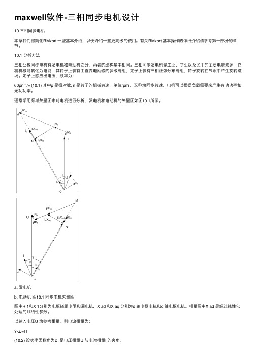
通常采⽤频域⽮量图来对电机进⾏分析,发电机和电动机的⽮量图如图10.1所⽰。
a. 发电机b. 电动机图10.1 同步电机⽮量图图中R 1和X 1分别为电枢绕组电阻和漏电抗,X ad 和X aq 分别为d 轴电枢电抗和q 轴电枢电抗。
相量图中X ad 是经过线性化处理的⾮线性参数。
以输⼊电压U 为参考相量,则电流相量为:-∠=I I(10.2) 设功率因数⾓为φ, 是电压相量U 与电流相量I 的夹⾓,图中OM 所代表的相量可表⽰为++-+++=motor for X X R generator for X X R OM aq 11aq 11)j j ()j j (I U I U (10.3) 设E 0与U 的夹⾓为θ,(对于发电机θ称为功率⾓,对于电动机θ,称为⼒矩⾓),则E 0与I 的夹⾓为θ?ψ+= (10.4)d 轴和q 轴电流可分别按下式求出==ψψcos sin I I I q d I (10.5)图中ON 相量代表由d 轴磁链所产⽣的d 轴反电势。
由磁路空载特性曲线,可确定E 0,X ad 和励磁电流I f1. 对于发电机:输出电功率:cos UI 3P 2=(10.6) 输⼊功率(机械功率) :ex Cuf add Fe Cua fw 21P P P P P P P P ++++++= (10.7) 式中:P fw , P Cua ,P Fe ,P add ,P cuf 和P ex 分别为风摩损耗、电枢铜损、铁⼼损耗、附加损耗、励磁绕组铜损和励磁机损耗输⼊机械转矩:ω11P T = (10.8)式中ω为同步⾓速度,单位:rad/s2. 对于电动机:输⼊电功率:cos UI 3P 1=(10.9) 输出机械功率:()ex Cuf add Fe Cua fw 12P P P P P P P P +++++-= (10.10) 式中:P fw , P Cua ,P Fe ,P add ,P cuf 和P ex 分别为风摩损耗、电枢铜损、铁⼼损耗、附加损耗、励磁绕组铜损和励磁机损耗输出机械转矩:ω22P T =(10.11) 电机效率:%100P P 12?=η(10.12) 10.2 主要特点10.2.1 适⽤于同步电动机和同步发电机凸极同步电动机和发电机结构基本相同,相量关系和计算⽅法有些差别,输出性能数据也有所不同。
maxwell软件- 直流电机
17 直流电机在用户已经掌握RMxprt 的基本使用的基础上,我们将一些过程简化,以便介绍一些更高级的使用。
有关RMxprt 的详细介绍请参考第一部分的章节。
17.1基本原理无论是直流发电机还是直流电动机,转子上都嵌有绕组,称为电枢绕组。
电枢绕组通过电刷和直流电源相连,电刷与换向器滑动连接。
当转子旋转时,电枢绕组在磁场中旋转并产生反电势。
定子上有P 对主磁极,主磁极由磁极铁心和套在上面的励磁绕组构成。
励磁绕组有并联和串联之分,励磁绕组在气隙中产生N 极和S 极交替排列的定子磁场。
并励绕组可以分为他励和自励两种,他励励磁绕组是由独立的直流电源供电,自励励磁绕组是由电枢绕组供电。
并励励磁绕组与电枢绕组并联,串励励磁绕组与电枢绕组串联。
对于复励型励磁绕组,RMxprt 假定电枢绕组先与串励励磁绕组串联,然后再与并励励磁绕组并联。
电刷组件与换向片始终保持接触,直流电经电刷和换向片流入旋转的电枢绕组时,产生了一个转子磁场。
由于换向器的机械整流作用,电枢绕组产生的转子磁场始终与定子磁场垂直。
定、转子磁场相互作用产生电磁力矩。
电枢电流产生的磁场称为电枢反应磁场,电枢反应磁场会导致换向不良。
为了消除由于电枢反应带来的磁场畸变,改善换向,可以在两个临近的主磁极间安装换向磁极和换向绕组,并在主磁极下安装补偿绕组。
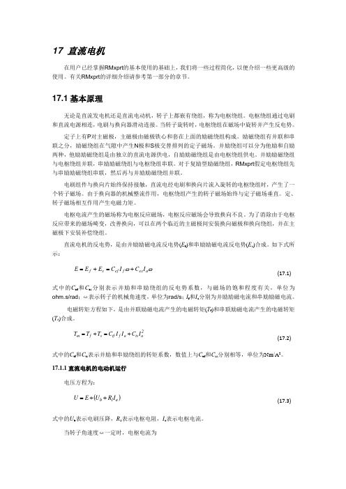
直流电机的反电势,是由并励励磁电流反电势(E f )和串励励磁电流反电势(E s )合成。
如下式所示:ωωa es f ef s f I C I C E E E +=+= (17.1)式中的C ef 和C es 分别表示并励和串励绕组的反电势系数,与磁场的饱和程度有关,单位为ohm.s/rad ;ω表示转子的机械角速度,单位为rad/s ;I f 和I a 分别为并励励磁电流和串励励磁电流。
电磁转矩方程如下,是由并联励磁电流产生的电磁转矩(T f )和串联励磁电流产生的电磁转矩(T s )合成。
2ats a f tf s f m I C I I C T T T +=+= (17.2)式中的C tf 和C ts 表示并励和串励绕组的转矩系数,数值上与C ef 和C ss 分别相等,单位为Nm/A 2。