Digimat介绍资料
Digimat总体介绍

9
Digimat-MF: Microstructure
Inclusion Phase(s)
Inclusion Shape (Ellipsoids of Revolution): Constant/Distribution
• Platelets (AR< 1) • Spheres (AR=1) • Fibers – Short – Long – Continuous
Outputs – At the macro & micro scales (i.e. composite & phase)
Stiffness & Compliance Matrices Coefficient of Thermal Expansion (CTE) Thermal Conductivity Electric Conductivity Stress-Strain Curves Strengths Distribution of stresses & strains in each phase of the composite
Automotive Aerospace Electronics & Consumer Products Wind Energy Defense Industrial Products Medical Devices Other: Academic, R&D Institutes, …
Thursday, November 24, 2011
Copyright© e-Xstream engineering, 2011
•2
Material Engineering with Mean Field & Finite Element based homogenization
SIGMA DP2 全能数码相机 说明书

先有DP1全球唯一配擁單反機描繪能力之便攜型數碼相機現有另一選擇DP2適馬DP2全能數碼相機集單反機強大功能於一身我們只稍作改動,讓攝影師更輕易掌握其創作力, 從中享受攝影藝術帶來之樂趣。
我們堅守信念,因為捕捉生命片段理應這樣。
無花巧忠於攝影基本原則,將最真實的面貌呈現眼前。
無論相機之形式或結構經過多少時代轉變,但一台好相機其定義是永恆不變的,這就是必須能拍出好的相片。
這正是適馬DP1之創作基本理念。
縱是機身纖巧,但所拍之照片質素卻從未如此之高, 我們另闢高效能機種之先河,並贏得一眾攝友之支持。
現今我們再為你介紹多一款型號, 助你拍出無價及無暇的作品。
相機真意義,從未如此滿意。
相機真意義從未如此滿意相片所示之DP2為實物原大。
02相機:適馬DP2,檔案:X3F RAW,曝光模式:光圈先決AE,ISO:100,白平衡:自動,快門:1/30秒,光圈:F2.8 焦距:24.2mm0304相機:適馬DP2,檔案:X3F RAW,曝光模式:光圈先決AE,ISO:100,白平衡:自動,快門:1/60秒,光圈:F2.8 焦距:24.2mm適馬DP:創新的相機系列當DP1首度面世,便贏得「神奇小子」的稱號。
DP1是DP系列之首部型號,其革命性的設計理念是將單反相機之基本元素及描繪能力裝嵌於一部便攜型機身身上,無人能聯想到這小小相機能拍出如單反機般之高質素相片,難怪大眾均感嘖嘖稱奇。
其實DP1所拍之相片能有着3-D立體般之細膩及色彩如現實般豐富,這是全賴Foveon x 3® 全色彩感測體所致,纖巧之便攜型機身卻擁單反相機之描繪能力,因此一面世便成一眾攝影愛好者或專業攝影師之寵兒。
DP1一方面機身小,可隨身攜帶,但另一方面卻能力大,描繪力足可打印漂亮大相,這種完美結合開拓攝影新一頁,亦立刻成為攝影愛好者之新寵兒,這是歸功於適馬堅持對攝影基本之信念。
不平凡照片往往來自平常生活對於特定事項,我們會預先準備單反機、其他高效能相機或更甚者是昂貴大片幅面相機作特殊用途,如家庭慶典、旅遊或特別事項,這些都是值得留念的時刻,然而你曾拍過的最佳照片是否均出於這類特定事項上呢?我猜不一定。
Digimat介绍资料511
DIGIMAT-MAP 支持的映射数据格式:
纤维方向 - *.o2d: MOLDEX3D - *.xml: Moldflow 3D - *.ele /*.xml: Moldflow Midplane - *.xml: Sigmasoft - *.mtc: REM3D - *.bou: Timon 3D - *.xml: Simpoe Mold - csv: -CT结果(Volume Graphics) - *.M01: PAM-FORM(编织材料) - *.xml: Digimat 开放格式(编织材料) 纤维含量(长纤维) - *.fcd: MOLDEX3D - csv: -CT结果(Volume Graphics) 纤维长度(长纤维) - *.fld: MOLDEX3D - *.xml: Moldflow Midplane 残余应力 - *.xml: Moldflow 3D - *.ele / *.xml: Moldflow Midplane - *.xml: Sigmasoft 温度场 - *.xml: Moldflow 3D - *.ele/*.xml: Moldflow Midplane - *.hou: Timon 3D 熔接线 - *.ele: Moldflow/Midplane - *.fou: Timon 3D - *.xml: Sigmasoft 孔隙率 - *.m2d: MOLDEX3D - *.xml: Moldflow Midplane - *.inp /*.xml: Magmasoft(铸造)
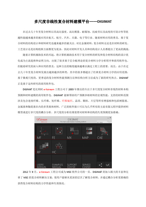
多尺度非线性复合材料建模平台——DIGIMAT
在过去几十年里复合材料以其高比强度、高比模量、耐腐蚀、抗疲劳以及高度的可设计性等优 越性能越来越多的被应用在航天、航空、汽车、兵器、电子等行业。随着材料应用的普及,基于复 合材料的结构设计和材料研究也越来越多的被关注。 对比金属材料, 复合材料无论是在材料的研发、 工艺设计还是结构校核方面都更为复杂,因此对材料开发人员和结构设计人员都提出了更高的挑战。 随着计算机辅助技术的兴起,将计算机辅助技术用于复合材料的研发和复合材料结构的设计优 化成为主流趋势和必然方向,出现了很多基于层合板理论的复合材料力学分析程序和商用软件包。 但随着研究的深入和应用的普及,这种方法的精度越来越难以满足工程上的需要。而且,由于在过 去几十年里复合材料发展出越来越多的种类,其中的很多都超出了经典复合材料力学的应用范围, 基于微观尺度的,更普适的复合材料性能预测方法和结构分析方法成为了新的研究热点。 DIGIMAT 正是基于这些研究的商用软件包。 DIGIMAT 是比利时 e-Xstream 工程公司于 2003 年推出的专注于多尺度复合材料非线性材料本构 预测和材料建模的商用软件包。DIGIMAT 能够帮助用户预测多相材料的宏观性能,支持的材料范围 涉及包含连续纤维、长纤维、短纤维、纤维编织、晶须、颗粒、片层等所有增强相和包括树脂基、 金属基和陶瓷基在内的多类基体材料。广泛的软件接口可以为几乎所有的主流有限元程序提供材料 模型或进行多尺度的耦合分析。多尺度的分析结果使得对材料和结构的失效预测更加准确。
TOUGHPIX DIGITHERM摄像机用户指南说明书

Congratulations - You are the owner of a TOUGHPIX DIGITHERMCAMERA. A compact pocket sized digital imaging camera capable of capturing true 5 megapixel visual images, along with fully radiometric thermal images.Overview4 Package Contents4 Getting To Know Your TOUGHPIX DIGITHERM6-7 Getting Started8 Taking Pictures9-10 Thermal Analysis11 Image Review12 Camera Setup13 Camera Status14 Downloading Files15 Web Browser16 Battery Pack17Try our online interactive DIGITHERM training!The interactive training programme will help youunderstand your TOUGHPIX DIGITHERM digitalimaging camera, what it is capable of and how tomake the most from your investment.Training available at /toughpix-digitherm-training CONTENTSREGISTERYOUR CORDEX PRODUCTSVisit to register and receive a 12 month extended warranty.To register your CorDEX product, click ‘My Account’ on the CorDEX homepage, login to your existing account or register , then enter your CorDEX product serial number and your product will appear with your extended warranty. Terms and conditions apply.Professional features in a pocket sized package. The TOUGHPIX DIGITHERM is a ruggedized, compact, high resolution digital imaging camera capable ofcapturing true 5 megapixel visual images along with fully radiometric thermal images, making this camera your go-to tool for fault finding, documentation whether your work is HVAC, building envelope inspections, electrical repair or facility maintenance.Check the contents of your TOUGHPIX DIGITHERM, it should include the following items:• TOUGHPIX DIGITHERM • Mains charger • Battery charging dock • User manual insert • Access key• CorDEX memory card • USB card reader • Wrist strap • Global adapters •Lithium-ion batteryOVERVIEWPACKAGE CONTENTSLED flash1With two modes of operation; Wide Area Burst mode and Close-up mode, you have the ability to control the flash to suit your requirements, helping prevent image washout.80x60 thermal sensor3Allowing Infrared vision with its super sensitive 80x60 thermal array as standard, provided 4800 individual measurement points on screen with a temperature range of -10˚C (14˚F)to +380˚C (716˚F).5MP sensor2Motorised auto focus, capable of resolving bothfine close up detail and wide area shots withoutthe need for macro-modes or additional lenses.WiFi enabled4No more messy cables, with the TOUGHPIXDIGITHERM, wirelessly transfer both infraredand visual images efficiently, even in thehazardous area.2.8” LCD backlit display7Compact enough to fit into any work pocket butrugged enough to take the hits, the TOUGHPIXDIGITHERM still has a screen big enough to viewimages taken in real time; day or night.Simple joystick navigation8With its simple joystick navigation, the menusare quick and easy to navigate, saving time onthe task in hand.Wrist strap point9Not only is the TOUHGPIX DIGITHERM small andcompact we have made it really easy to carrywith our CorDEX wrist strap, which can be wornon either the right or left hand side of the camera.Removable rechargeable battery5Rechargeable lithium ion battery pack providinga huge four hours runtime plus the ability toswitch packs and keep working if you need to(only in a safe area).Ruggedized aluminium body6Manufactured from lightweight aircraft gradealuminium, the TOUGHPIX DIGITHERM is bothrugged and tough with one goal in mind, qualitythat’s built to last.12345678 9GETTING TO KNOW YOUR TOUGHPIX DIGITHERMBattery PackPlease ensure the battery pack is fully charged where possible for optimum results and maximumruntime. The battery pack is removed and inserted via the access door on the base of the camera. The battery pack is charged using the docking station supplied. Refer to the section on battery pack operation for details.Turning the Power ON/OFFUse the power button on the top of the camera to turn the camera on and off. The on button is identified on the top of the camera with the ON/OFF symbol located next to the shoot button.Please refer to Time and Date section if setup is required before operation.Camera Interface MenusAll camera settings and features are navigated and selected using the joystick:Short press enters the camera menu Long press enters the analysis menuCAMERA MENUThis menu has the following icons:Visible ImagingIR ImagingImage ReviewWIFITime and DateFirmwareANALYSIS MENUThis menu has the following icons:SPOT & BOX ConfigurationGLOBAL IR parameterGETTING STARTEDTAKING PICTURESVisible ImagingControls the VISIBLE imaging and capture modes.•LED: flash operation options.DISABLED: LED flash turned OFF. ENABLED: LED flash turned ON.AUTO: LED flash enabled dependent on ambient light.•FLASH CHARGE STATUS: the top right of the display shows:GREEN indicates fully charged. RED indicates charging in progress.•TIME LAPSE : Sets time period for delay from shoot-button activation. TIME LAPSE PERIOD: single, 30 sec, 1 min, 2 min, 5 min. ACTIVATION: Started and stopped by the shoot-button. INDICATOR (top left): Shows current setting (in seconds). When running shows the time to next image.•TL THRESHOLD : Sets the temperature threshold for the time lapse to start. TEMPERATURE: Sets the threshold temperature (-10˚C disables). ACTIVATION: Started and stopped by the shoot-button.To focus an image, point the camera at the target of interest and the camera willautomatically focus. Once the camera is focused and the image is clear, press theshoot button whilst the camera takes the shot.TAKING PICTURESIR ImagingControls the IR imaging and display modes.• IMAGE TYPE: sets the IR display modes.HIGHLIGHT: Overlays highest temperatures only for hot stop locating.ATB:Overlays Adaptive Thermal Blending areas determined by ATB highand ATB low settings.THERMAL ONLY: IR image only is displayed.VISIBLE ONLY: VISIBLE image only is displayed.• COLOURISATION: Configures the IR image colour palette (as displayed on the colour bar for reference). Industry Standard colour palettes are available:Rainbow, Amber, Sepia, Grey positive, Grey negative, Iron, Hot metal.• ATB HIGH: Selects the temperature threshold above which the ATB overlay is active.ATB HIGH ACTIVATE: Enable or Disable.TEMPERATURE: selects the temperature threshold.• ATB LOW: Selects the temperature threshold below which the ATB overlay is active.ATB LOW ACTIVATE: Enable or Disable.TEMPERATURE: selects the temperature threshold.• RANGE: Selects IR temperature range.Low: low range -10°C to 140°CHigh: high range -10°C to 380°C• UNITS: Selects the global temperature units.TEMPERATURE UNITS: Celsius, Fahrenheit, Kelvin.THERMAL ANAL YSISSPOT ConfigurationConfigures the active temperature measurement SPOTS & BOX operation.• SPOTS/BOX: Configures the number of active SPOTS in the display/BOX display.Options selectable: 1-SPOT, 2-SPOT, 3-SPOT, BOX.• MOVE SPOT/BOX: Selects the ACTIVE SPOT or BOX corner to be moved by the joystick in the preview display.Options selectable: 1,2,3 to select the active SPOT (displayed in bold in thepreview display).• SPOT1/BOX EMISSIVITY: Configures emissivity of SPOT1 and also the BOX area.Options selectable: 0.5 to 1.0 in steps on 0.05.• SPOT2 EMISSIVITY: Configures emissivity of SPOT2.Options selectable: 0.5 to 1.0 in steps on 0.05.• SPOT3 EMISSIVITY: Configures emissivity of SPOT3.Options selectable: 0.5 to 1.0 in steps on 0.05.Global IR ParameterConfigures the GLOBAL IR parameters used by the IR radiometric analysis. These parameters are shared by all the SPOTS and the BOX area are displayed on the preview display.• REFLECTED T: Configures the GLOBAL reflected temperature.Options selectable: -10C to 380C.• ATMOSPHERIC T: Configures the GLOBAL atmospheric temperature.Options selectable: -10C to 380C.• HUMIDITY: Configures the GLOBAL humidity.Options selectable: 0% to 100% in steps of 1%.• DISTANCE:Configures the GLOBAL distance of the object from the camera.Options selectable: 1m to 100m in steps of 1m.Image ReviewDisplays the stored VISIBLE and IR images for review.The memory card empty icon is displayed when no memory card is present.The joystick is used to navigate the stored images.• RIGHT and LEFT: moves through the stored images.• UP and DOWN: selects either VISIBLE or corresponding IR image. •PUSH (short): selects full display of the currently displayed image.UP: to view VISIBLE image DOWN: to review the IR image•PUSH (short): enters the Delete Image menu.CANCEL: re-enter the Image Review.DELETE: deletes the image from the memory card.WIFIWIFI access point activation.•ENABLE WIFI: select NOW to enable, PUSH (short) to exit WIFI access point.When WIFI access point is enabled the display shows the following:• CAMERA SSID IS DISPLAYED: used to identify the camera for selecting WIFI connection.• CAMERA IP ADDRESS: used by browser to display web-page.•FW: WIFI firmware revision.Refer to the section on the Web browser for image review using a browser.IMAGE REVIEWCAMERA SETUPTime and DateUsed to setup the cameras date and time.• YEAR : select current year.• MONTH : select current month.• DAY : select current day.• HOUR : select current hour.• MINUTE : select current minute.• SECOND : select current second.•TIME ZONE : select current time zone offset (hours).Firmware and AlignmentBoth WIFI and camera system firmware are uploaded form this menu.Displays the current FIRMWARE for the camera. See WIFI for the module firmware.Displays the camera serial number: 8-digit Hexa-decimal number.•UPDATE FIRMWARE: Camera system firmware update. Press NOW to update firmware.•UPDATE WIFI: WIFI firmware update. Press NOW to update firmware.•ALIGN: IR and VISIBLE image alignment.Arrows are used to align the IR and VISIBLE images.Separate instructions for firmware updates will be issued along with the firmwareupdate file.Battery StatusShows current battery charge status as a percentage.Calibration Nofication:Lower right of screen when activated to indicate calibration is due.Memory Card Empty:Top left of screen when activated indicates no memory card is present.CAMERA STATUSDOWNLOADING FILESImages can be downloaded from the TOUGHPIX DIGITHERM via the removable memory card or via the WIFI access point.Removable Memory CardTOUGHPIX DIGITHERM is supplied complete with a memory card**.• Open the Battery Pack door of the camera with the supplied access key. • Remove the Battery Pack from the camera. • Remove the memory card from the camera.• Insert the memory card in to the memory card reader supplied.•Remove the other end of the memory card reader which will reveal a USB dongle, insert this in to your PC/Laptop.** Only compatible with the TOUGHPIX DIGITHERM.WIFI Access DownloadTOUGHPIX DIGITHERM comes complete with built in WIFI to enable users to wirelessly view and download images directly from the camera.To access images over the WIFI:• Activate the DIGITHERM WIFI access point (refer to the WIFI icon description). •Access and view files via DIGITHERM web browser operation or CorDEX DIGITHERM application*.Refer to the section on web browser operation.* Refer to CorDEX for current camera application support details.WEB BROWSER OPERATION The integrated DIGITHERM web browser enables display and download ofon-camera images in the original view-mode via the DIGITHERM’s WIFI access point.Basic OperationThe web browser displays thumbnail images for quick transfer with download access to the full resolution images. Once downloaded, images can be viewed and processed in CONNECT Software to adjust the view mode.• WIFI: Web server enables fast applicationand browser access to display images.• Image view mode displayed on web-server shows captured images includingcolour bar and temperature scale.• Active BOX or SPOTS and temperaturemin/max locations are displayed withouttemperatures. The colour bar can be usedto get the approximate temperature forthese locations.• Direct linked full resolution downloadsavailable as shown in the example.RIGHT CLICK: the link to download theVISIBLE or IR image.LEFT CLICK: to open full resolution image.Note: the IR and VISIBLE are not completely aligned in the browser views. Please note• Both VISIBLE and IR images are required for full analysis in CONNECT and these need to be downloaded separately.BATTERY PACKRemoving the Battery Pack• Open the Battery Pack door of the camera with the supplied access key.• Remove the Battery Pack from the camera.Inserting the Battery Pack• Open the Battery Pack door of the camera with the supplied access key.• Slide the Battery Pack into the camera.• Secure the Battery Pack in place using the supplied access key.• Ensure the access door is securely closed before entering any restricted areas. Charging the Battery Pack• Plug the charger into a wall socket/outlet. The GREEN LED will illuminate showing mains power is connected and that the charger is ready.• Insert DIGITHERM Battery Pack into the charging station. Care must be taken to ensure that the battery is inserted in the correct orientation, otherwise battery or charger damage may occur.• If the battery is properly located in the charging station, the RED LED on the charger will illuminate to indicate charging. Once the charge cycle is complete, the LED will change to GREEN.Notes:Notes:。
DigiLife DV说明书概论
用户手册
1
目录
第1节 了解相机................................................................................................................3 第2节 准备使用................................................................................................................6 第3节 录制模式................................................................................................................8 第4项 播放模式..............................................................................................................28 第5节 收听MP3音乐 .....................................................................................................38 第6节 在PC上观看MPEG4影片 .................................................................................40 第7节 在TV上观看相片和影片....................................................................................41 第8节 从AV 设备录制影片 .........................................................................................42 第9节 MPEG4视频格式转换.......................................................................................43 第10节 制作DVD ...........................................................................................................47 第11节 将资料传送到计算机.......................................................................................50 第12节 规格与系统要求 ...............................................................................................57
Abaqus Digimat培训
Abaqus培训1.Abaqus概述:Abaqus是一套功能强大的工程模拟的有限元软件,其解决的问题的范围从相对简单的线形分析到许多复杂的非线形问题。
2.CAE基础介绍:CAE指用计算机求解分析复杂工程和产品的结构力学性能,以及优化结构性能等。
CAE软件可作静态结构分析,动态结构分析,研究线形、非线形问题,分析结构(固体)、流体、电磁等。
3.Abaqus界面介绍:①几何建模Part②划分网格Mesh③特性设置Property④建立装配体Assembly⑤定义分析步Step⑥相互作用Interaction⑦载荷边界Load⑧提交运算Job⑨后处理Visualization4.Abaqus基本操作:旋转模型: Ctrl+Alt+鼠标左键平移模型: Ctrl+Alt+鼠标中键缩放模型: Ctrl+Alt+鼠标右键4.静力学分析练习:①导入几何模型bsd_asm.stp②进入部件平台,将原复杂模型切割成若干个简单Cell。
③进行网格划分④定义材料属性,定义截面属性,分配截面属性。
⑤导入装配体模块,利用旋转、平移、约束命令调整装配位置。
⑥建立分析步⑦进入Interaction模块,建立Tie约束。
⑧进入Load模块,选择固定端,建立边界条件(固定)。
施加重力载荷。
⑨进入Job管理器,提交运算,打开监控截面进行实时监控。
⑩运算完成后,输出应力云图和位移云图。
得到结果数据。
5.静力分析例子1-方形板按压测试加载;①建立Part-1部件,绘制300x200平板模型(可变形、壳、平面)②建立Part-2部件,绘制草图、利用旋转命令绘制直径30mm 的离散刚性探头。
创建参考点。
③定义材料属性,创建截面属性,分配截面属性。
④导入装配体,调整探头与平板的位置。
⑤建立分析步⑥相互作用模块中,建立接触约束,法向行为和切向行为均采取默认值。
选择刚性体作为主面,平板作为从面。
⑦载荷模块中,选择两侧边创建边界条件,完全固定,限制六个方向自由度。
DIGIMAT软件详解
系统 ,为仿真模拟和席拟样机提供 了一个 口扩展旦并不昂贵的高 1
性 能计 算 解 决 方 案 。 “ O S L 司为 代 表 的科 学 与工 程 软件 开 发 商正 在积 极 开 以C M O 公 发 能 够 在 Wn o sH CS re 0 8 id w P ev r20 系统 下 运 行 的 大型 工具 包 ,这 些 性 能 优 异 、功 能 强 大 的开 发 工 具可 以有 效 地 帮助 科 学 家和 工 程 师 们 大幅 提 升 他 们探 索和 发 现新 事 物 的 速度 , ”微软 公 司 高性 能
模 态 分 析 结 果 与 实 验 比 较 。 从 图 中可 知 ,采 用 DG M T 料 模 型 II A 材 与 实 验 结 果 误 差 在 5 以 内 ,这 是 因为 DGM T 料 模 型 可 以考 虑 % I IA 材
2II; A1 汽 车 行 业 的 应 用 . (t 在 ) M ’ p
汽车行 业是一个 高速发展 的行 业 ,其竞争也 目趋激烈 ,在 这种情况 下 ,新产品推 出的速度也越来越快 ,这也对行业的C E A
图1 应 力 一 变 曲线 应
应 用提 出了越 来越高的要求。C E A 技术为汽车行业 的高速 发展提 供具有 中心价值地位 的技术保障 ,可以为企业带来 巨大的技术经 济效益。 由于复合材料 的高性能、低成本等优越性能 ,汽车部件 越来越广泛地采 用复合材料 ,这也对C E A 模拟技术提 出了新 的挑 战 ,因为传统C E A 中的材料模型通常不考虑纤维取 向等 因素,这 会给计算机仿真带来较大 的误差。 图5 是采用D GM T I IA 材料 模型整合有 限元技术 在汽车保险杠
只 有 在 用 户 亲 身体 验 后 ,才 能完 全 地 体 会 到 新 魅 力所 在 。 代 仿真 软 件 的
Digimat介绍资料
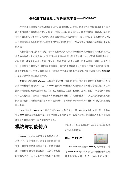
考虑Lemaitre-Chaboche损伤的弹塑性 弹粘塑性、热弹粘塑性
Norton / Power / Prandtl模型 粘弹粘塑性
粘弹粘塑性本构
DIGIMAT-MF 支持的微观结构:
多增强相夹杂 层合板 椭球拓扑增强相(球状、片层状、短纤维、连
FPGF 模型 (First Pseudo-Grain Failure 模型), 本构模型。
用于短纤维增强材料的渐进失效
失效准则可建立在宏观和单相(纤维、基体等)
等不同尺度上
失效模型包含:最大应力、最大应变、Tsai-Hill
2D & 3D、Azzi-Tsai-Hill 2D、Tsai-Wu 2D & 3D、
弹粘塑性(有限应变): Leonov-EGP模型 热学模型:
傅立叶定律 电学模型:
欧姆定律
如增强材料的形状、增强材料的体积含量、增
强材料的方向分布、铺层信息等就可以快速获
得均化后的材料本构。
考虑Lemaitre-Chaboche损伤的弹塑性模型
DIGIMAT-MF 中的均化算法:
Mori-Tanaka法 双夹杂法 第一阶和第二阶均化 多级多步均化
更加准确。
2012 年 9 月,eXstream 工程公司成为 MSC 软件公司的一员。DIGIMAT 的加入极大的丰富和完
善了 MSC 的复合材料解决方案,使用户能够从更深的层次了解复合材料,并通过耦合分析更准确的
获得复合材料结构的力学性能和失效情况。
模块与功能特点
件的接口,以及蜂窝或泡沫夹芯结构的虚拟设 计和虚拟实验等。
DIGIMAT-MF 可以对所有增强相为椭圆形拓扑的 多相材料进行快速准确的性能预测,获得刚度 矩阵和工程常熟,并可通过定义失效准则和虚 拟实验的加载条件,给出虚拟实验曲线。
Digimat总体介绍

Thursday, November 24, 2011
6
•3
Digimat-MF & Digimat-FE: Micro-Mechanics
Global behavior
E
Localization
r x
Challenges in Modeling composite Multi-scale Approach for Materials and Structures.
B. Alsteens & Z. El Hachemi
What is DIGIMAT ?
Is The nonlinear multi-scale material modeling platform Used by Material Engineers Structural Engineers At Material Suppliers Tier 1 (Material Users/Any Industry) OEM (Material Users/Any Industry) For Material Engineering Accurate & Efficient FEA of “Composite” Structures
7
Mean Field homogenization
•4Βιβλιοθήκη Digimat-MF: Material Models
Mechanical (For each phase of a multi-phase material)
Elastic: Viscoelastic Hyperelastic: Neo-Hookean / Mooney-Rivlin / Ogden / Swanson / Storakers Elasto-Plastic: • J2-Von Mises Plasticity • Generalized Drucker-Prager ElastoPlastic with Damage
MAX1978中文数据手册

用于Peltier模块的集成温度控制器概论MAX1978 / MAX1979是用于Peltier热电冷却器(TEC)模块的最小, 最安全, 最精确完整的单芯片温度控制器。
片上功率FET和热控制环路电路可最大限度地减少外部元件, 同时保持高效率。
可选择的500kHz / 1MHz开关频率和独特的纹波消除方案可优化元件尺寸和效率, 同时降低噪声。
内部MOSFET的开关速度经过优化, 可降低噪声和EMI。
超低漂移斩波放大器可保持±0.001°C的温度稳定性。
直接控制输出电流而不是电压, 以消除电流浪涌。
独立的加热和冷却电流和电压限制提供最高水平的TEC保护。
MAX1978采用单电源供电, 通过在两个同步降压调节器的输出之间偏置TEC, 提供双极性±3A输出。
真正的双极性操作控制温度, 在低负载电流下没有“死区”或其他非线性。
当设定点非常接近自然操作点时, 控制系统不会捕获, 其中仅需要少量的加热或冷却。
模拟控制信号精确设置TEC 电流。
MAX1979提供高达6A的单极性输出。
提供斩波稳定的仪表放大器和高精度积分放大器, 以创建比例积分(PI)或比例积分微分(PID)控制器。
仪表放大器可以连接外部NTC或PTC热敏电阻, 热电偶或半导体温度传感器。
提供模拟输出以监控TEC温度和电流。
此外, 单独的过热和欠温输出表明当TEC温度超出范围时。
片上电压基准为热敏电阻桥提供偏置。
MAX1978 / MAX1979采用薄型48引脚薄型QFN-EP 封装, 工作在-40°C至+ 85°C温度范围。
采用外露金属焊盘的耐热增强型QFN-EP封装可最大限度地降低工作结温。
评估套件可用于加速设计。
应用光纤激光模块典型工作电路出现在数据手册的最后。
WDM, DWDM激光二极管温度控制光纤网络设备EDFA光放大器电信光纤接口ATE特征♦尺寸最小, 最安全, 最精确完整的单芯片控制器♦片上功率MOSFET-无外部FET♦电路占用面积<0.93in2♦回路高度<3mm♦温度稳定性为0.001°C♦集成精密积分器和斩波稳定运算放大器♦精确, 独立的加热和冷却电流限制♦通过直接控制TEC电流消除浪涌♦可调节差分TEC电压限制♦低纹波和低噪声设计♦TEC电流监视器♦温度监控器♦过温和欠温警报♦双极性±3A输出电流(MAX1978)♦单极性+ 6A输出电流(MAX1979)订购信息* EP =裸焊盘。
日本三丰MITUTOYO数显千分尺
日本三丰MITUTOYO数显千分尺前言日本是一个著名的制造业强国,其经济依赖于制造业和出口。
其制造业以汽车、电子设备、机械设备等为主,其产品的质量一直以来都有着世界顶级的水平。
其中,数显千分尺是一种常见的测量工具,具有极高的精度和稳定性,而日本三丰MITUTOYO数显千分尺更是全球著名的高级品牌之一。
什么是数显千分尺?数显千分尺是一种测量长度、深度等物理量的工具,其主要特点是使用数字显示,读数快速、方便,同时精度非常高。
一般来说,数显千分尺具有以下几个特点:•高精度:能够达到0.01mm的精度,比普通的游标千分尺更加精确。
•数字显示:数字显示,读数方便、快速。
•便捷性:要比刻度式千分尺更加便捷、易于上手。
•稳定性好:使用寿命长,且精度不随使用寿命减少而降低。
日本三丰MITUTOYO数显千分尺日本三丰是一家著名的测量工具制造商,其生产的MITUTOYO品牌的数显千分尺,堪称数显千分尺的代表产品之一。
主要包括以下几种:MITUTOYO 500-196-20/30这种数显千分尺是MITUTOYO旗下最常使用的型号之一,其特点在于:•读数精度高,为0.01mm。
•显示屏幕为LCD液晶显示器,数字清晰。
•可以保留上一次测量的值,防止误差叠加。
•底座为钢制底座,耐用、稳定。
MITUTOYO ABSOLUTE 500-196-30这种尺子同样采用了数字显示技术,但是比MITUTOYO 500-196-20/30更加精确,其特点在于:•读数精度为0.001mm,比MITUTOYO 500-196-20/30更加精确。
•显示屏幕为LCD液晶显示器,数字显示清晰。
•可以对读数进行零点调整,减少误差。
总结作为数显千分尺的最高品质代表之一,日本三丰MITUTOYO数显千分尺以其高精度、稳定性好和长寿命等特点在测量领域得到了广泛的应用。
在测量领域,正确选择合适的测量工具非常重要,不仅能提高工作效率,也能提高精度,使结果更加准确。
基于Digimat复合材料分析平台的SFRP性能分析
2
公司以及产品介绍
e-Xstream工程公司
> 成立于2003年,专注于复合材料的高质量建模领域 > 2012年9月加入MSC,成为MSC全资子公司 > 在欧洲拥有两个办公室,并派驻MSC全球多个办事处 > 目前团队总计60余人
– PhD: 50% – 工程师: 90%
– 残余应力
– 温度场
模
–
熔接线位置
流 分
析
网 格
结 构 分 析
网 格
16
DIGIMAT 与有限元软件的直接接口
> 材料模型在CAE中的调用——以Marc Mentat为例
17
DIGIMAT 与有限元软件的直接接口
添加Digimat材料模型文件 添加纤维方向映射结 果 选择对应的Section 替换模型上已有的材料
提交有限元 软件计算
ห้องสมุดไป่ตู้
有限元模型
材料定义
20
20
DIGIMAT涵盖了改性塑料零部件的多种性能分析
> NVH
– 线弹性
> 刚度
– 弹塑性 – 温度相关
> 冲击失效
– 弹粘塑性 – 应变率相关 – SFRP失效模型
> 蠕变
– 粘弹 – 弹粘塑
> 耐久性
21
Digimat针对SFRP零部件的仿真案例
短切纤维增强塑料汽车发动机散热器仿真
– 更完整的测试程序将产生更高的参数置信度
> 完全碰撞装载(行人)
> 在一个组件中利用Digimat局部各向异性替换各向同性模型,3-5%的计算成本的增 加
36
MAXIM MAX338 MAX339 数据手册

The MAX338/MAX339 are monolithic, CMOS analog multiplexers (muxes). The 8-channel MAX338 is designed to connect one of eight inputs to a common output by control of a 3-bit binary address. The dual, 4-channel MAX339 is designed to connect one of four inputs to a common output by control of a 2-bit binary address. Both devices can be used as either a mux or a demux. On-resistance is 400Ωmax, and the devices conduct current equally well in both directions.These muxes feature extremely low off leakages (less than 20pA at +25°C), and extremely low on-channel leakages (less than 50pA at +25°C). The new design offers guaranteed low charge injection (1.5pC typ) and electrostatic discharge (ESD) protection greater than 2000V, per method 3015.7. These improved muxes are pin-compatible upgrades for the industry-standard DG508A and DG509A. For similar Maxim devices with lower leakage and charge injection but higher on-resis-tance, see the MAX328 and MAX329.The MAX338/MAX339 operate from a single +4.5V to +30V supply or from dual supplies of ±4.5V to ±20V.All control inputs (whether address or enable) are TTL compatible (+0.8V to +2.4V) over the full specified tem-perature range and over the ±4.5V to ±18V supply range. These parts are fabricated with Maxim’s 44V sili-con-gate process.________________________ApplicationsData-Acquisition Systems Sample-and-Hold Circuits Test Equipment Heads-Up Displays Military RadiosCommunications Systems Guidance and Control SystemsPBX, PABX____________________________Features♦On-Resistance, <400Ωmax ♦Transition Time, <500ns ♦On-Resistance Match, <10Ω♦NO-Off Leakage Current, <20pA at +25°C ♦1.5pC Charge Injection♦Single-Supply Operation (+4.5V to +30V)Bipolar-Supply Operation (±4.5V to ±20V)♦Plug-In Upgrade for Industry-Standard DG508A/DG509A ♦Rail-to-Rail Signal Handling ♦TTL/CMOS-Logic Compatible♦ESD Protection >2000V, per Method 3015.7Ordering InformationMAX338/MAX3398-Channel/Dual 4-Channel,Low-Leakage, CMOS Analog Multiplexers________________________________________________________________Maxim Integrated Products 1_____________________Pin Configurations/Functional Diagrams/Truth Tables19-0272; Rev 3; 11/04Ordering Information continued at end of data sheet.*Contact factory for dice specifications.**Contact factory for availability.For pricing, delivery, and ordering information,please contact Maxim/Dallas Direct!at 1-888-629-4642, or visit Maxim’s website at .General DescriptionM A X 338/M A X 3398-Channel/Dual 4-Channel,Low-Leakage, CMOS Analog Multiplexers 2_______________________________________________________________________________________ABSOLUTE MAXIMUM RATINGSELECTRICAL CHARACTERISTICS—Dual Supplies(V+ = +15V, V- = -15V, GND = 0V, V AH = +2.4V, V AL = +0.8V, T A = T MIN to T MAX , unless otherwise noted.)Stresses beyond those listed under “Absolute Maximum Ratings” may cause permanent damage to the device. These are stress ratings only, and functional operation of the device at these or any other conditions beyond those indicated in the operational sections of the specifications is not implied. Exposure to absolute maximum rating conditions for extended periods may affect device reliability.Voltage Referenced to V-V+............................................................................-0.3V, 44V GND.........................................................................-0.3V, 25V Digital Inputs, NO, COM (Note 1)...........(V- - 2V) to (V+ + 2V) or30mA (whichever occurs first)Continuous Current (any terminal)......................................30mA Peak Current, NO or COM(pulsed at 1ms, 10% duty cycle max)..........................100mAContinuous Power Dissipation (TA = +70°C)Plastic DIP (derate 10.53mW/°C above +70°C)..........842mW Narrow SO (derate 8.70mW/°C above +70°C)............696mW 16-Pin TQFN (derate 21.3mW/°C above +70°C).......1702mW CERDIP (derate 10.00mW/°C above +70°C)...............800mW Operating Temperature RangesMAX33_C__........................................................0°C to +70°C MAX33_E__......................................................-40°C to +85°C MAX33_MJE ..................................................-55°C to +125°C Storage Temperature Range.............................-65°C to +150°C Lead Temperature (soldering, 10sec).............................+300°CNote 1:Signals on NO, COM, EN, A0, A1, or A2 exceeding V+ or V- are clamped by internal diodes. Limit forward current to maximum current ratings.MAX338/MAX3398-Channel/Dual 4-Channel,Low-Leakage, CMOS Analog Multiplexers_______________________________________________________________________________________3ELECTRICAL CHARACTERISTICS—Dual Supplies (continued)(V+ = +15V, V- = -15V, GND = 0V, V AH = +2.4V, V AL = +0.8V, T A = T MIN to T MAX , unless otherwise noted.)M A X 338/M A X 3398-Channel/Dual 4-Channel,Low-Leakage, CMOS Analog Multiplexers 4_______________________________________________________________________________________ELECTRICAL CHARACTERISTICS—Single Supply(V+ = +12V, V- = 0V, GND = 0V, V AH = +2.4V, V AL = +0.8V, T A = T MIN to T MAX , unless otherwise noted.)Note 2:The algebraic convention where the most negative value is a minimum and the most positive value a maximum is used inthis data sheet.Note 3:Guaranteed by design.Note 4:ΔR ON = R ON(MAX)- R ON(MIN).Note 5:Leakage parameters are 100% tested at the maximum rated hot temperature and guaranteed by correlation at +25°C.Note 6:Worst-case isolation is on channel 4 because of its proximity to the drain pin. Off isolation = 20log V COM /V NO , whereV COM = output and V NO = input to off switch.MAX338/MAX3398-Channel/Dual 4-Channel,Low-Leakage, CMOS Analog Multiplexers_______________________________________________________________________________________5600ON-RESISTANCE vs. V COM(DUAL SUPPLIES)500010*******-2020-1515-1010-55400V COM (V)R O N (Ω)ON-RESISTANCE vs. V COM OVER TEMPERATURE (DUAL SUPPLIES)100200300-1515-1010-550400V COM (V)R O N (Ω)12001400ON-RESISTANCE vs. V COM(SINGLE SUPPLY)100002004006001520105800V COM (V)R O N (Ω)600700ON-RESISTANCE vs. V COM OVER TEMPERATURE (SINGLE SUPPLY)500010020030015105400V COM (V)R O N (Ω)30CHARGE INJECTION vs. V COM200-30-20-100-1515-1010-55010V COM (V)Q j (p C )40100.0001-55125OFF LEAKAGE vs. TEMPERATURE1TEMPERATURE (°C)O F F L E A K A G E (n A )250.010.001-35-15650.1100100045851055100.0001-55125ON LEAKAGE vs. TEMPERATURE1TEMPERATURE (°C)O N L E A K A G E (n A )250.010.001-35-15650.11001000458510551000.001-55125SUPPLY CURRENT vs. TEMPERATURE10TEMPERATURE (°C)I +, I - (μA )250.10.01-35-156514585105510006001000900800700TRANSITION TIME vs.POWER SUPPLIES5000100200300OR 10V(SINGLE)OR 5V(SINGLE)400SUPPLY VOLTAGE (V)t T R A N S (n S )__________________________________________Typical Operating Characteristics(T A = +25°C, unless otherwise noted.)__________Applications InformationOperation withSupply Voltages Other than 15VUsing supply voltages less than ±15V will reduce the analog signal range. The MAX338/MAX339 switches operate with ±4.5V to ±20V bipolar supplies or with a +4.5V to +30V single supply. Connect V- to GND when operating with a single supply. Both device types can also operate with unbalanced supplies such as +24V and -5V. The Typical Operating Characteristics graphs show typical on-resistance with 20V, 15V, 10V, and 5V supplies. (Switching times increase by a factor of two or more for operation at 5V.)Overvoltage ProtectionProper power-supply sequencing is recommended for all CMOS devices. Do not exceed the absolute maxi-mum ratings, because stresses beyond the listed rat-ings may cause permanent damage to the devices.Always sequence V+ on first, then V-, followed by the logic inputs NO and COM. If power-supply sequencing is not possible, add two small signal diodes in series with supply pins for overvoltage protection (Figure 1).Adding diodes reduces the analog signal range to 1V below V+ and 1V above V-, but does not affect the devices’ low switch resistance and low leakage charac-teristics. Device operation is unchanged, and the differ-ence between V+ and V- should not exceed 44V.M A X 338/M A X 3398-Channel/Dual 4-Channel,Low-Leakage, CMOS Analog Multiplexers 6_____________________________________________________________________________________________________________________________________________________Pin DescriptionFigure 1. Overvoltage Protection Using External Blocking DiodesMAX338/MAX3398-Channel/Dual 4-Channel,Low-Leakage, CMOS Analog Multiplexers_______________________________________________________________________________________7______________________________________________Test Circuits/Timing DiagramsFigure 2. Transition TimeM A X 338/M A X 3398-Channel/Dual 4-Channel,Low-Leakage, CMOS Analog Multiplexers 8________________________________________________________________________________________________________________________Test Circuits/Timing Diagrams (continued)Figure 5. Charge InjectionMAX338/MAX3398-Channel/Dual 4-Channel,Low-Leakage, CMOS Analog Multiplexers_______________________________________________________________________________________9_________________________________Test Circuits/Timing Diagrams (continued)Figure 6. Off-Isolation Figure 7. CrosstalkFigure 8. NO/COM CapacitanceM A X 338/M A X 3398-Channel/Dual 4-Channel,Low-Leakage, CMOS Analog Multiplexers 10______________________________________________________________________________________________Pin Configurations/Functional Diagrams/Truth Tables (continued)A2A1A0EN ON SWITCH X 00001111X 00110011X 01010101011111111None 12345678MAX338LOGIC “0” V AL ≤ 0.8V, LOGIC “1” V AH ≥ 2.4VA1A0EN ON SWITCH X 0011X 010101111None 1234MAX339LOGIC “0” V AL ≤ 0.8V, LOGIC “1” V AH ≥ 2.4VMAX338/MAX3398-Channel/Dual 4-Channel,Low-Leakage, CMOS Analog Multiplexers______________________________________________________________________________________11Ordering Information (continued)*Contact factory for dice specifications.**Contact factory for availability.Pin Configurations/Functional Diagrams/Truth Tables (continued)M A X 338/M A X 3398-Channel/Dual 4-Channel,Low-Leakage, CMOS Analog Multiplexers 12________________________________________________________________________________________________________________________________________________Chip TopographiesV+NO3EN 0.114"(2.89mm)0.078"(1.98mm)COM NO8NO5NO6N07A0A1A2GNDNO2 NO1 V-N.C.NO4V+NO3AEN0.114"(2.89mm)0.078"(1.98mm)COMA COMB NO1B NO2B N04BA0A1N.C.GNDNO2A NO1A V-NO3BNO4ATRANSISTOR COUNT: 224SUBSTRATE IS INTERNALLY CONNECTED TO V+Note:On Thin QFN packages connect exposed pad to V+.TRANSISTOR COUNT: 224SUBSTRATE IS INTERNALLY CONNECTED TO V+MAX338MAX339N.C. = NO INTERNAL CONNECTIONMAX338/MAX3398-Channel/Dual 4-Channel,Low-Leakage, CMOS Analog MultiplexersMa xim ca nnot a ssume responsibility for use of a ny circuitry other tha n circuitry entirely embodied in a Ma xim product. No circuit pa tent licenses a re implied. Maxim reserves the right to change the circuitry and specifications without notice at any time.Maxim Integrated Products, 120 San Gabriel Drive, Sunnyvale, CA 94086 408-737-7600 ____________________13©2004 Maxim Integrated ProductsPrinted USAis a registered trademark of Maxim Integrated Products.Package Information(The package drawing(s) in this data sheet may not reflect the most current specifications. For the latest package outline information,go to /packages .)。
SUPER DYMA 在中国

SD拥有超群的防腐防锈性能
超出以往材料数倍的防腐能力 断面自动修复能力 超强的耐碱性环境的能力
优异的加工性能
加工部位的防腐不受影响 更耐划伤 适用于各种焊接及彩涂加工
具有更佳的性价比的新材料
去除了后涂镀的繁琐 因强耐腐可部分替代不锈钢或铝 提高了产品的寿命,降低了综合成本
在加工时请您注意—Superdyma 具有出色的油漆前处理性
。 被油漆的Superdyma,其切割面及横切部分少有因腐蚀引起的漆膜脱离,耐腐蚀性能极佳。 建筑材料CCT30循环
热镀锌 Z27
深镀锌 Y18
镀铝AZ150
镀铝镁锌K18
在加工时请您注意—Superdyma焊接性能
由于Superdyma 各种性能的发挥是以较薄的镀膜为前提,故不会因镀膜过厚而影响焊接。 Superdyma 适用于各种焊接方式(电弧重叠角焊、点焊等)。 点焊部分的耐腐蚀性 Superdyma与Superzinc一样,随着循环的增加保护膜将覆盖焊接部分、从而抑制红锈的产生。
圆筒拉深部分的耐腐蚀性能
Superdyma即使圆筒拉深部其耐腐蚀性能也与平面部同样,具有卓越的耐腐蚀性。 圆筒拉深部的耐腐蚀性能(周期腐蚀试验结果)
样品 钢板厚度 热镀锌 1.0mm SUPERDYMA 1.0mm 耐腐蚀性试验条件: 以下列1~3为一周期反复进行。 1. 盐水喷雾2小时(5% NaCl 35 ℃ ) 2. 干 燥 4小时(60℃ 温度30 ℃ ) 3. 湿 润 2小时(50℃ 温度98%以上) 单面镀敷附着量 铬处理附着量 95g/m2 40mg/m2 130g/m2 15mg/m2 拉探试验条件: ■ 冲头径50∮ ■ 拉深比2.0 ■ 冲模凸缘R10 ■ 防皱压力0.51ton 备注 实机材料 实机材料
DIGIMAT软件详解
雪廖’雪彩
∞
R有在闩产亲身体验后,才能完全地体会到新一代偈真软*的
魅力所在。■
…^MS自j口口em㈣o∞m肺
万方数据
Ⅲ7
蠢曩鏊侯琳houl@。。…。
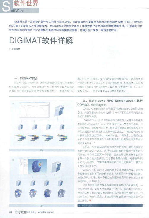
目4是纤摊毁向对其增强饕料在两方向托伸摆量的影响.并 比鞍了宴验结果与DIGIMAT计算结粜。对比后发现.采用D】GIHAT
q
DI(:IMAT
MF
D rG]MAT
w足通过均匀化一i傻适准确地预目惺台材杠的
¥蛭m}2为。速幔块幂2单胞理论.郭绱复合柑科划升i最
m单i,升#腚义蓦忸、增强体等柯斟的结构性能以及增强协
台置,绍台娟关材料摸望l摇1]rucker—prager模型等I计算盅
DIGII&^T在*泉复々村料十的E月
纳*复台杜科是自两种或两种以±的国相{少在雏“绑 米纽太小(】一100rim)复台而成酌盟☆材料。速些量埕目蚪是:E品 质、半晶质、晶质或燕而南之,也可啦世有机嘶、走*.韧或=
程冗鞍仁^B^叫S等可辅确宴现基于细札甚竣的盟音材M再鲁目
31wGIM^I—Mx
啦纳求复台材科晕电g。从斟中可知,H奇当碳纳米管埔加到 一是程度甜,整个材科才会导电.这为实验设计提供7{月能
参考依据。
分在外界载荷n的槽应历精。
DIGiMAT—H)【是为材料供应商和终端用户z问提供DIGIMAT材
杠磋型托准备、存储、提取和安全变换。用户可以充分利Ⅷ此攘 型击询树杠常数.进行逆向T程.即由已知的复合材牡硬型反半
井效益。日于复舍材料的高性能、{E,靠本等优越性靛,汽车前件 蔗象越r{地共用复亡材料,选也对CAE模拟技¥提&7哥的桃
digimarc水印技术原理

digimarc水印技术原理Digimarc水印技术原理引言:随着数字化时代的到来,信息的传播和共享变得日益便捷,然而,数字化也带来了信息被篡改和盗用的问题。
为了保护数字内容的版权和真实性,数字水印技术应运而生。
Digimarc水印技术作为一种先进的数字水印技术,具有高度隐蔽性和稳定性,被广泛应用于版权保护、防伪溯源等领域。
本文将详细介绍Digimarc水印技术的原理及其应用。
一、Digimarc水印技术的基本原理Digimarc水印技术采用嵌入式数字水印的方式,将水印信息嵌入到数字媒体中,实现对数字内容的追踪和验证。
其基本原理如下:1. 嵌入过程:Digimarc水印技术通过对数字媒体进行变换和编码,将水印信息嵌入到媒体中。
嵌入过程基于信号处理和信息隐藏的原理,通过改变媒体的特征参数,如像素值、频域特征等,将水印信息嵌入到媒体中。
嵌入的水印信息通常是一串数字或二维码,可以包含版权信息、所有者信息等。
2. 提取过程:Digimarc水印技术通过对带有水印的数字媒体进行解码和分析,提取出嵌入的水印信息。
提取过程基于信号处理和信息识别的原理,通过对媒体进行特征提取和匹配,识别出嵌入的水印信息。
提取的水印信息可以用于验证数字内容的真实性、追踪版权归属等。
二、Digimarc水印技术的优势Digimarc水印技术相比其他数字水印技术具有以下优势:1. 高度隐蔽性:Digimarc水印技术能够将水印信息嵌入到数字媒体中,几乎不可察觉。
嵌入的水印信息不影响媒体的视觉和听觉效果,不会引起用户的注意。
2. 稳定性:Digimarc水印技术嵌入的水印信息具有很高的稳定性。
即使经过压缩、裁剪、格式转换等处理,水印信息依然能够被提取出来。
这使得Digimarc水印技术在数字内容的传输和存储过程中具有良好的适应性。
3. 大容量性:Digimarc水印技术能够嵌入大量的水印信息。
通过合理的编码和嵌入算法,可以在数字媒体中嵌入数百个甚至上千个水印信息,满足不同应用场景的需求。
D-type flip-flop

signal (FOF,FON). A control input (SW,SWN) is connected to the bases of a pair of control transistors (430) whose collectors are connected to the two output conductors (C1,CN1) of the bistable units while the emitters are connected together to the collector of one transistor in a transistor pair (420,421) whose bases are connected to the bistable output (ON, OFF).
申请人:KONINKLIJKE PHILIPS ELECTRONICS N.V. 地址:Groenewoudseweg 1 5621 BA Eindhoven NL 国籍:NL 代理机构:Caron, Jean 更多信息请下载全文后查看
专利内容由知识产权出版社提供
专利名称:D-type flip-flop 发明人:RIDGERS, TIMOTHY 申请号:Байду номын сангаасP 97204 003.4 申请日:19971218 公开号:EP0851582A1 公开日:19980701 专利附图:
摘要:The flip-flop has two bistable units (431, 433) which are coupled by another pair of transistors (432). These produce two internal bistable outputs (C2,CN2) which are connected to the base of respective transistors of the transistor followers (434, 435) while the base of the complementary transistor in each pair is connected to the test input
digimat案例

digimat案例Case Study:digimat案例研究:digimatDigimat is a material solutions company that provides digital materials for various industries.Digimat是一家材料解决方案公司,为各种行业提供数字化材料。
Their digital materials are designed to replace traditional materials and offer superior performance, durability, and sustainability.他们的数字化材料旨在取代传统材料,并提供卓越的性能、耐用性和可持续性。
In this case study, we will explore how Digimat has successfully implemented digital materials in the automotive, aerospace, and sports industries.在本案例研究中,我们将探讨Digimat如何在汽车、航空航天和体育行业成功实施数字化材料。
First, let"s look at the automotive industry.首先,让我们看看汽车行业。
Digimat has developed digital materials that can replace traditional metal and plastic components in vehicles, resulting in lighter, stronger, and more fuel-efficient cars.Digimat开发了可以替代车辆中传统金属和塑料部件的数字化材料,从而使汽车更轻、更强且更节能。
These digital materials also offer superior thermal management properties, which can improve the overall performance and safety of vehicles.这些数字化材料还具有卓越的热管理性能,可以提高车辆的整体性能和安全性。
- 1、下载文档前请自行甄别文档内容的完整性,平台不提供额外的编辑、内容补充、找答案等附加服务。
- 2、"仅部分预览"的文档,不可在线预览部分如存在完整性等问题,可反馈申请退款(可完整预览的文档不适用该条件!)。
- 3、如文档侵犯您的权益,请联系客服反馈,我们会尽快为您处理(人工客服工作时间:9:00-18:30)。
DIGIMAT 针对材料开发人员和结构分析人 员提供了六个主要模块,涵盖多相材料的性能 预报、材料微观结构建模与分析、材料数据管 理、材料模型的实验数据校对、工艺分析结果 的读取与映射、工艺仿真软件和结构有限元软
DIGIMAT-MF
DIGIMAT-MF 是基于 Eshelby 夹杂理论,采 用 Mean Field 均匀化方法的多相材料非线性材 料本构预测工具。作为一种半分析方法,
2D 机织物的建模
变情况的模块。通过定义单相材料的材料本构
DIGIMAT-MF 支持的虚拟实验加载:
单调加载、循环加载、自定义历程加载 多向应力应变载荷 力学载荷、热力学载荷 预测热传导和导电性能 加载有限元软件分析结果
DIGIMAT-MF 支持的失效模式:
模型,微结构的几何特征即可采用相应的随机 算法生成材料微观结构特征单元的随机几何模 型,并通过调用商用有限元程序计算材料微观 结构上的应力应变分布情况,并可在后处理中 分析应力应变的分布概率以及材料的等效均化
FPGF 模型 (First Pseudo-Grain Failure 模型), 本构模型。
用于短纤维增强材料的渐进失效
失效准则可建立在宏观和单相(纤维、基体等)
等不同尺度上
失效模型包含:最大应力、最大应变、Tsai-Hill
2D & 3D、Azzi-Tsai-Hill 2D、Tsai-Wu 2D & 3D、
去几十年里复合材料发展出越来越多的种类,其中的很多都超出了经典复合材料力学的应用范围,
基于微观尺度的,更普适的复合材料性能预测方法和结构分析方法成为了新的研究热点。DIGIMAT
正是基于这些研究的商用软件包。
DIGIMAT 是比利时 eXstream 工程公司于 2003 年推出的专注于多尺度复合材料非线性材料本构
弹粘塑性(有限应变): Leonov-EGP模型 热学模型:
傅立叶定律 电学模型:
欧姆定律
如增强材料的形状、增强材料的体积含量、增
强材料的方向分布、铺层信息等就可以快速获
得均化后的材料本构。
考虑Lemaitre-Chaboche损伤的弹塑性模型
DIGIMAT-MF 中的均化算法:
Mori-Tanaka法 双夹杂法 第一阶和第二阶均化 多级多步均化
多尺度非线性复合材料建模平台——DIGIMAT
在过去几十年里复合材料以其高比强度、高比模量、耐腐蚀、抗疲劳以及高度的可设计性等优
越性能越来越多的被应用在航天、航空、汽车、兵器、电子等行业。随着材料应用的普及,基于复
合材料的结构设计和材料研究也越来越多的被关注。对比金属材料,复合材料无论是在材料的研发、
微观结构上的应力应变分布
mises 应力分布
均化结果
先进的材料查询工具
逆向工程是 MX 的另一个重要功能。复杂本 构模型的单相材料(如树脂、界面相、杂质相) 的力学性能往往是很难获得的,需要大量的实 验。逆向工程可以帮助用户利用少量的宏观实 验曲线,通过逆向回归迭代,得到需要修正的
单相材料的材料本构。由于复合材料往往由于 材料缺陷和工艺缺陷,呈现实际材料的应力应 变曲线与理论模型存在偏差的现象,使用逆向 工程可以将这些缺陷造成的非线性特征考虑在 材料模型中,从而使材料模型更加贴近实际情 况。
的残余应力,甚至产生分层或断裂。ISEMP 利用 DIGIMAT-FE 建立了层合板的微观结构,经过计 算发现,层合板在固化过程中,层间的剪切应 力水平很高,容易导致分层。纤维与树脂界面 处也表现出较高的应力水平,这些高应力区域 有时会形成材料横向断裂的裂纹扩展路径。
Drucker-Prager塑性模型 + 与压力相关的弹塑性模型
考虑Lemaitre-Chaboche损伤的弹塑性 弹粘塑性、热弹粘塑性
Norton / Power / Prandtl模型 粘弹粘塑性
粘弹粘塑性本构
DIGIMAT-MF 支持的微观结构:
多增强相夹杂 层合板 椭球拓扑增强相(球状、片层状、短纤维、连
Mentat 植入界面
应变能分析结果
DIGIMAT-CAE
树脂上的失效
纤维上的失效
DIGIMAT-CAE 是 DIGIMAT 与其他有限元程序 的接口,通过 DIGIMAT-CAE,工艺仿真软件、 DIGIMAT-MF 和结构仿真软件被连接起来,从而 实现考虑工艺影响的,多尺度耦合的结构有限 元仿真。
- Moldflow Mid-Plane
蜂窝定义 蜂窝夹层结构
三点弯曲定义
使用 DIGIMAT 结合有限元软件,TICONA 成 功分析了汽车天窗上的纤维增强塑料件的力学 性能,仿真预测的失效位置和失效方式与实验 结果十分吻合
虚拟实验结果
Micross 支持的失效模式
芯材 - 最大应力
蒙皮 - 最大应力 - Tsai-Wu - Tsai-Hill - Azzi-Tsa金属材料是汽车轻量化 主要方向之一。TRELLEBORG 使用 DIGIMAT 与商 用有限元程序耦合,成功准确预测了采用短切 玻璃纤维增强树脂制造的发动机底座的静强度 和疲劳性能,为他们采用复合材料替代铝合金 材料提供了依据
汽车天窗构件的性能分析与失效判断
福特汽车采用 DIGIMAT 与自己构建的材料 数据库以及其他有限元软件耦合,建立了针对 车用纤维增强塑料结构的设计预报平台,通过 该平台,福特能够更准确的了解增强塑料结构 的极限强度,从而使他们的设计更加轻质优化。 福特汽车认为,采用该平台有希望突破乘用车 复合材料用量不超过 10%的瓶颈。
纤维方向的映射
- Moldflow 3D - REM3D - SigmaSoft - 3D Timon
Micross
夹层结构(蜂窝或泡沫)以轻质,高结构 稳定性等特点被越来越多的应用在航空航天工 业。然而由于实际的试样试验中无法避免夹具 产生的应力集中,在这样的应力集中下,蜂窝 结构极容易被压扁,因此很难采用实际实验准 确获得蜂窝夹层板的力学性能。Micross 是一个 蜂窝夹层结构的虚拟实验平台。在 Micross 中, 用户通过定义蜂窝的基本几何形状和材料本构, 定义蒙皮材料,通过调用自带的有限元求解程 序即可以实现对蜂窝夹层板三点弯曲、四点弯 曲、面内剪切等典型实验结果的预测,并自动 生成分析报告。
Hashin-Rotem 2D、Hashin 2D & 3D等
与应变率相关的失效准则 Leonov-EGP或超弹材料的失效准则
相比 MF 方法,DIGIMAT-FE 能够模拟的增强
相几何形状更为广泛,软件提供了多种用于描
述增强相的基本几何拓扑,并可通过几何的重
叠干涉获得更为复杂的增强相几何,此外还可
DIGIMAT-MF 支持的单相材料本构模型:
力学/热力学本构
线弹性、热线弹性 各向同性、横观各向同性、 正交各向异性、各向异性
线粘弹性 弹塑性、热弹塑性
J2 塑性模型 +各向同性硬化 -Power/Exponential/ Exponential
linear 模型 +动力硬化 - cyclic elastoplasticity 模型
2D 界面脱粘
3D 界面脱粘
微观结构分析的后处理主要分为两部分。
首先是商用有限元程序中的后处理结果,在 FEA
软件的后处理中可以得到纤维和树脂上的应力
应变分布,相应失效因子的分布,以及界面脱
粘情况。另外还可以用过 DIGIMAT-FE 的后处理
对纤维和树脂上的应力应变分布进行统计,获
得分布概率和平均结果。
续纤维) 增强相长径比分布概率定义 增强相方向定义(统一方向、随机方向、二阶
分布矢量) 空洞夹杂 界面相定义 刚体、准刚体、变形体增强相
椭球拓扑增强相
DIGIMAT-FE
DIGIMAT 是通过建立反应材料微观结构特
征的代表性体积单元(RVE),并通过有限元分
析获取材料均化性能和微观尺度上局部应力应
DIGIMAT-MF 可以对所有增强相为椭圆形拓扑的 多相材料进行快速准确的性能预测,获得刚度 矩阵和工程常熟,并可通过定义失效准则和虚 拟实验的加载条件,给出虚拟实验曲线。
在 DIGIMAT-MF 中,只需要输入每一相材料 的材料本构,通过定义复合材料的微结构信息,
超弹性(有限应变)
Neo-Hookean / Mooney-Rivlin / Ogden / Swanson/ Storakers (可压缩泡沫)模型
工艺的研发还是在结构的设计方面都更为复杂,因此对材料开发人员和结构设计人员都提出了更高
的挑战。
随着计算机辅助技术的兴起,将计算机辅助技术用于复合材料的研发和复合材料结构的设计优
化成为主流趋势和必然方向,出现了很多基于层合板理论的复合材料力学分析程序和商用软件包。
但随着研究的深入和应用的普及,这种方法的精度越来越难以满足工程上的需要。而且,由于在过
纤维方向分布
映射结果统计对比
DIGIMAT-MAP 支持的网格格式:
- Patran
- Abaqus
- ANSYS
- Ideas
- LS-DYNA
- PAM-CRASH
- RADIOSS
- REM3D
- SAMCEF
- 3D Timon
DIGIMAT-MAP 支持的映射数据格式:
- DIGIMAT
- Moldex3D
逆向工程
逆向工程支持的回归数据:
材料本构 (热)线弹性 粘弹性 (热)弹塑性 (热)弹粘塑性
其他可回归的特征数据: 纤维长径比 失效模型中的材料强度 材料性能与温度的相关性
DIGIMAT-CAE 支持的 FEA 软件:
- Nastran Sol400,Sol600,Sol700 - MSC.Marc - Abaqus/CAE, Standard & Explicit - ANSYS Mechanical - LS-DYNA, Implicit & Explicit - Optistruct - PAM-CRASH - RADIOSS - SAMCEF-Mecano
