Sonix_松翰指令用户指南
松翰单片机SONIXSN8P2511程序模板
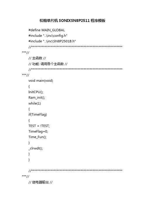
松翰单片机SONIXSN8P2511程序模板#define MAIN_GLOBAL#include "..\inc\config.h"#include "..\inc\SN8P2501B.h"//************************************************************* ***//// 主函数 //// 功能: 调用各个主函数 ////************************************************************* ***//void main(void){InitCPU();Ram_init();while(1){if(TimeFlag){TEST = !TEST;TimeFlag=0;Time_Fun();}_clrwdt();}}//************************************************************* ***//// 继电器输出 //// 功能: 工作输出 ////************************************************************* ***//void Work_Fun(void){;}//************************************************************* ***//// 硬件初始化 //// 功能: 硬件初始化输入输出定时器开关 AD初始化 ////************************************************************* ***//void InitCPU(void) //单片机初始化{FGIE=0; //关总中断//------------------------------I/O口输出--------------------------//---------------P0---------------FP00M=0;//// FP01M=1;//// FP02M = 0;// FP03M = 0;// FP04M=0;//P0UR = _0000_0001b;//---------------P1---------------FP10M=0;//// FP11M=0;//FP12M=1;// 输出FP13M=0;// 按键// FP14M=1;//// FP16M=1;//// FP15M=1;//// FP17M=1;//P1UR = _0000_1001b;//---------------P2---------------FP20M=0;//FP21M=0;//FP22M=0;//FP23M=0;//FP24M=0;//FP25M=0;//// FP26M=0;//// FP27M=1;//P2UR = _0011_1111b;//---------------P5---------------// FP50M=1;//// FP51M=1;//// FP52M=1;//// FP53M=0;//FP54M=1;//// P5UR = _0000_0000b;//------------------------------T0--------------------------------FT0ENB = 0;FT0IEN = 0;FT0IRQ = 0;T0M = 0X60;//时钟为FCPU/4T0C=7; //T0 间隔250uSFT0ENB = 1;FT0IEN = 1;FGIE=1; //开总中断}//************************************************************* ***//// 变量初始化函数 //// 功能: 对程序中的变量进行赋初值 ////************************************************************* ***//void Ram_init(void){_nop();_nop();Move_Key = 0x70;// Open_FLAG = 1;}//************************************************************* ***//// 走时函数 //// 功能: 对程序中计时功能进行计数和赋值 ////************************************************************* ***//void Time_Fun(void){static uchar Time_5ms_Cnt = 0,Time_10ms_Cnt =0,Time_200ms_Cnt = 0,Time_1S_Cnt = 0;static uchar Leave_Out_ID = 0,Leave_Out_Time_Cnt = 0,YiWei_ID = 0,Leave_Out_Cnt = 5;static uchar Move_IN_Cnt = 0;uchar tmp1;if(Leave_Data_Out_Flag){if(!Leave_Out_ID){Leave_Out_Time_Cnt ++;LEAVE_DATA_OUT_ON();if(Leave_Out_Time_Cnt > 8){Leave_Out_Time_Cnt = 0;Leave_Out_ID = 1;}}else if(Leave_Out_ID == 1){Leave_Out_Time_Cnt ++;LEAVE_DATA_OUT_OFF();if(Leave_Out_Time_Cnt > 5){Leave_Out_Time_Cnt = 0;Leave_Out_ID = 2;}}else if(Leave_Out_ID == 2){if(!Leave_Out_Time_Cnt){tmp1 = Leave_ID;tmp1 |= Move_Key;tmp1 >>= YiWei_ID;tmp1 &= 1;if(tmp1)Leave_Out_Time_Cnt = 0;elseLeave_Out_Time_Cnt = 2; YiWei_ID ++;if(YiWei_ID >= 9){Leave_Out_ID = 0;YiWei_ID = 0;Leave_Out_Time_Cnt = 0; Leave_Data_Out_Flag = 0;}}if(Leave_Data_Out_Flag){Leave_Out_Time_Cnt ++;if(Leave_Out_Time_Cnt <= 4) LEAVE_DATA_OUT_ON();else if(Leave_Out_Time_Cnt < 6) LEAVE_DATA_OUT_OFF();elseLeave_Out_Time_Cnt = 0;}}}Time_5ms_Cnt ++;if(Time_5ms_Cnt >= 5) //接收5ms去扫描{Time_5ms_Cnt = 0;if(MOVE_IN) //倾倒了{Move_IN_Cnt ++;if(Move_IN_Cnt >= 10){Move_IN_Cnt = 15;Move_Key = 0x80;Leave_ID = 0;}}else{if(!K8_IN)Leave_ID = 8;else if(!K7_IN)Leave_ID = 7;else if(!K6_IN)Leave_ID = 6;else if(!K5_IN)Leave_ID = 5;else if(!K4_IN)Leave_ID = 4;else if(!K3_IN)Leave_ID = 3;else if(!K2_IN)Leave_ID = 2;else if(!K1_IN)Leave_ID = 1;Move_IN_Cnt = 0;Move_Key = 0x70;}}Time_10ms_Cnt ++;if(Time_10ms_Cnt >= 10) //发送10MS去扫描{Time_10ms_Cnt = 0;}Time_200ms_Cnt ++;if(Time_200ms_Cnt >= 200){Time_200ms_Cnt = 0;if(!Leave_Data_Out_Flag){Leave_Out_Cnt ++;if(Leave_Out_Cnt >= 10){Leave_Out_Cnt = 0;Leave_Data_Out_Flag = 1;}}}}__interrupt isr1(void) //TC0定时器中断入口{static uchar Time1MS = 0;if(FT0IRQ) //TC0 //定时0.125ms{T0C=6; //T0 间隔250uSTime1MS ++;if(Time1MS >= 4) //1MS中断函数{Time1MS = 0;TimeFlag = 1;}}FT0IRQ = 0;}。
MP-PRO WRITER松翰烧录器使用说明

ww w
SONiX TECHNOLOGY CO., LTD
Page 2
Version1.0
MP PRO Writer 使用手册
修改记录
版本 V10
日期
说明
2010 年 4 月 初版
tw
com
avantcom
3.6 Handler模式设置................................................................................................................................... 17
44 脱机操作 ....................................................................................................................................................... 18 4.1 上电自检 ............................................................................................................................................... 18
55 故障处理 ....................................................................................................................................................... 22
松翰选型手册

的 USB 类型
液 串 晶 口 显 示 SN8F22511B 10K 闪存 512 8 8 4 1 7/1 SSOP16 全速 USB2.0, 支持控制/ 3 中断 SN8F2251B 10K 闪存 512 8 8 4 1 7/0 采用 QFN16 全速 USB2.0, 支持控制/ 3 中断 SN8F22521B 10K 闪存 512 8 12 4 2 1 7/2 SOP20/SSOP20 全速 USB2.0, 支持控制/ 3 中断 SN8F22531B 10K 闪存 512 8 16 4 2 1 7/2 QFN24 全速 USB2.0, 支持控制/ 3 中断 SN8F2253B 10K 闪存 512 8 16 4 2 1 7/2 SOP24 全速 USB2.0, 支持控制/ 3 中断 SN8F2255B 10K 闪存 512 8 24 4 2 1 7/2 的 LQFP32 全速 USB2.0, 支持控制/ 3 中断 SN8F2271B 5K 闪光 192 8 10 2 1 5/1 采用 QFN16 低速 USB2.0 接口,支持控 制/ 2 中断 SN8F22721B 5K 闪光 192 8 14 2 1 1 5/2 DIP20/SOP20/SSOP20 低速 USB2.0 接口,支持控 制/ 2 中断 诠释 包 分机 其他特点
程序 零件编号 存储 器
RAM (8 位) 堆
的
ADC DAC 的
定 PWM 时 的蜂鸣 器 器
中断
IO 的
SN8F2280 系列
的 USB 类型
液 零件编号 程序存 RAM (8 储器 位) 堆 的 IO ADC 的 DAC 的 器 定 时 PWM 的 串 蜂鸣器 口 晶 显 示 中断诠 包 释分机 其他特点
松翰烧写器MP-III Writer 使用说明

指示 LED
执行按键 烧录扩展口 MP 转接板
烧录座
用途 复位烧录器 选择功能模式 显示烧录信息与功能指示 烧录状态指示。绿色表示烧录完成,黄色表示烧录中, 红色表示烧录失败 用于执行烧录或中止报警提示 用于自行外引连线烧录芯片 用于插接烧录转接板,必须与 MCU 型号相匹配 放置待烧录芯片(仅适用于 DIP 或可转为 DIP 封装) 的芯片
Version 1.1
MP-III Writer User’s Manual
目录
修改记录 .........................................................................................................................................................................2
1.2 功能概述
采用具有 ISP 功能的 Flash Base MCU,联机状态时根据需要可升级芯片烧录控制程序; Full Speed USB1.1 接口可方便与 PC 互联,从而进行烧录器升级、联机烧录芯片或下载芯片烧录代码; 支持芯片联机和脱机烧录操作; 继承 MPI Writer 所有功能; 新增联机状态下,读取芯片资料的功能; 新增联机状态下,读取 EEPROM 和清空 EEPROM 等功能。
松翰单片机SN程序
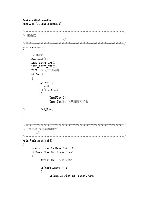
#define MAIN_GLOBAL#include "..\inc\config.h"//*****************************************************************// // 主函数////*****************************************************************// void main(void){InitCPU();Ram_init();LED1_LEAVE_OFF();LED2_LEAVE_OFF();FGIE = 1;//开启中断while(1){_clrwdt();_nop();if(TimeFlag){TimeFlag=0;Time_Fun(); //基准时间函数}// Red_Fun();}}//*****************************************************************// // 继电器负载输出函数////*****************************************************************// void Work_scan(void){static uchar CaiDeng_Cnt = 0;if(Open_Flag && !Error_Flag){MOTOR2_ON();//同步电机if(Heat_Leave == 1){if(Fan_ON_Flag && !YanShi_Cnt)YanShi_Cnt = 4;else if(!Fan_ON_Flag){FENG_MOTOR1_ON();//风机Fan_ON_Flag = 1;}if(YanShi_Cnt >= 4){HEAT1_ON();Heat1_ON_Flag = 1;}HEAT2_OFF();Heat2_ON_Flag = 0;}else if(Heat_Leave == 2){if(Fan_ON_Flag && !YanShi_Cnt)YanShi_Cnt = 4;else if(!Fan_ON_Flag){FENG_MOTOR1_ON();//风机Fan_ON_Flag = 1;}if(YanShi_Cnt >= 4){HEAT1_ON();Heat1_ON_Flag = 1;}if(YanShi_Cnt >= 8){HEAT2_ON();Heat2_ON_Flag = 1;}}else{if(YanShi_Cnt >= 60){Fan_ON_Flag = 0;FENG_MOTOR1_OFF();}HEAT1_OFF();Heat1_ON_Flag = 0;HEAT2_OFF();Heat2_ON_Flag = 0;}if(CaiDeng_Leave == 1){LED_RED = 1;LED_GREEN = 0;LED_BLUE = 0;}else if(CaiDeng_Leave == 2){LED_RED = 0;LED_GREEN = 1;LED_BLUE = 0;}else if(CaiDeng_Leave == 3){LED_RED = 0;LED_GREEN = 0;LED_BLUE = 1;}else if(CaiDeng_Leave == 4){LED_RED = 1;LED_GREEN = 1;LED_BLUE = 1;}else if(CaiDeng_Leave == 5){if(!CaiDeng_Cnt){LED_RED = 1;LED_GREEN = 0;LED_BLUE = 0;}else if(CaiDeng_Cnt == 30){LED_RED = 0;LED_GREEN = 1;LED_BLUE = 0;}else if(CaiDeng_Cnt == 60){LED_RED = 0;LED_GREEN = 0;LED_BLUE = 1;}else if(CaiDeng_Cnt == 90){LED_RED = 1;LED_GREEN = 1;LED_BLUE = 1;}CaiDeng_Cnt ;if(CaiDeng_Cnt >= 120){CaiDeng_Cnt = 0;}}else{LED_RED = 0;LED_GREEN = 0;LED_BLUE = 0;}}else{MOTOR2_OFF();//同步电机HEAT1_OFF();//加热器1Heat1_ON_Flag = 0;HEAT2_OFF();//加热器2Heat2_ON_Flag = 0;LED1_LEAVE_OFF();//2档灯LED2_LEAVE_OFF();//1档灯LED_HUOYAN_OFF();//火焰LED_RED = 0;LED_GREEN = 0;LED_BLUE = 0;if(YanShi_Cnt >= 60 || Error_Flag){Fan_ON_Flag = 0;FENG_MOTOR1_OFF();//关闭风机}}}/***************************************************************** 红外输入判断函数__MAIN_EXTERN uchar Red_In_Cnt;//按键值__MAIN_EXTERN uchar Red_Data;//按键值__MAIN_EXTERN uchar Old_Red_Data;//按键值__MAIN_EXTERN uchar Red_ID;*****************************************************************/ void Red_Fun(void){// static uchar Red_Data_Bit_Cnt = 0;// TEST = !TEST;// if(Red_In_Cnt >= 100)// {// Red_ID = 0;// Red_Data = 0;// Red_Data_Bit_Cnt = 0;// Red_In_Cnt = 0;// }// if(!Red_ID)// {// if(RED_IN)// {// if(Red_In_Cnt >= 60&&Red_In_Cnt <= 84)// {// Red_ID = 1;// }// Red_In_Cnt = 0;// }// }// else if(Red_ID == 1)// {// if(!RED_IN)// {// if(Red_In_Cnt >= 26&&Red_In_Cnt <= 46)// {// Red_ID = 2;// }// else// Red_ID = 0;// Red_In_Cnt = 0;// }// }// else if(Red_ID == 2)// {// if(RED_IN)// Red_ID = 3;// Red_In_Cnt = 0;// }// if(Red_ID == 3)// {// if(!RED_IN)// {// if(Red_In_Cnt>=3)// {// Red_Data <<= 1;// if(Red_In_Cnt >=10)// Red_Data |= 1;// Red_Data_Bit_Cnt ;// if(Red_Data_Bit_Cnt == 8)// {// if(Red_Data != _0100_0000b) // {// Red_ID = 0;// Red_Data_Bit_Cnt = 0; // }// Red_Data = 0;// }// if(Red_Data_Bit_Cnt == 24)// {// Red_Down_Flag = 1;// Old_Red_Data = Red_Data; // Red_ID = 0;// Red_Data_Bit_Cnt = 0;// Red_Data = 0;// }// Red_In_Cnt = 0;// }// }// }}//*****************************************************************// // 时基走时函数////*****************************************************************// void Time_Fun(void){static uchar Time5MS_Cnt = 0,Time10MS_Cnt = 0,Time100MS_Cnt = 0,Time500MS_Cnt = 0;static uchar T10S_Cnt = 0,T30min_Cnt;static uchar Buzz_ON_Cnt = 0,Error_Cnt = 0,PingDao_Cnt = 0;Time5MS_Cnt ;if(Time5MS_Cnt >= 5) //5MS时间基准{Time5MS_Cnt = 0;// AD_fun();}Time10MS_Cnt ;if(Time10MS_Cnt >= 10) //10MS时间基准{Time10MS_Cnt = 0;KeyFun();// LedDisplay();if(Buzz_Flag){Buzz_ON_Cnt ;if(Buzz_ON_Cnt >= 15){Buzz_ON_Cnt=0;Buzz_Flag = 0;}}}Time100MS_Cnt ;if(Time100MS_Cnt >= 100)//100MS时间基准{Time100MS_Cnt = 0;Time500MS_Cnt ;if(Time500MS_Cnt >= 5){Time500MS_Cnt = 0;if(YanShi_Cnt <70){YanShi_Cnt ;}if(SanSuo_Time){SanSuo_Time --;}elseSanSuo_Flag = 0;if(YuYue_Time){T10S_Cnt ;if(T10S_Cnt >= 20)//10S{T10S_Cnt = 0;T30min_Cnt ;if(T30min_Cnt >= 180)//180=30分钟{T30min_Cnt = 0;YuYue_Time --;if(!YuYue_Time){Open_Flag = 0;Buzz_Flag = 1;Heat_Leave = 0;YanShi_Cnt = 0;HuoYan_Leave = 3;YuYue_Time = 0;}}}}}Work_scan();// if(!PINGDAO_IN)// {// PingDao_Cnt ;// if(PingDao_Cnt >= 10)// {// Error_Flag = 1;// Open_Flag = 0;// }// }if(Error_Flag){if(Error_Cnt <= 100)Error_Cnt ;if(Error_Cnt == 10||Error_Cnt == 20||Error_Cnt == 30){Buzz_Flag = 1;}}}}/*****************************************************************按键处理//--------------------按键值-----------------------------------#define RED_KEY_ON_OFF _1101_1000b #define RED_KEY_HEATER1 _0010_1000b#define RED_KEY_FLAME_UP _0110_1000b#define RED_KEY_TIME_0011_0000b#define RED_KEY_HEATER2 _0000_1000b #define RED_KEY_FLAME_DOWN _0100_1000b#define KEY_ON_OFF 1#define KEY_HEATER1 6#define KEY_FLAME_UP 5#define KEY_TIME 4#define KEY_HEATER2 3#define KEY_COLDURS 2*****************************************************************/ void KeyFun(void) //单片机初始化{static uchar Key_Cnt = 0;if(!Error_Flag){Scan_Key();if(Red_Down_Flag)//红外按键赋值{Red_Down_Flag = 0;switch(Old_Red_Data){case RED_KEY_ON_OFF:{Key_Data = KEY_ON_OFF;}break;case RED_KEY_HEATER1:{Key_Data = KEY_HEATER1;}break;case RED_KEY_FLAME_UP:{Key_Data = KEY_FLAME_UP;}break;case RED_KEY_TIME:{Key_Data = KEY_HEATER_OFF;}break;case RED_KEY_HEATER2:{Key_Data = KEY_HEATER2;}break;case RED_KEY_FLAME_DOWN:{Key_Data = KEY_COLDURS;}break;default:break;}Old_Red_Data = 0;}switch(Key_Data){case KEY_ON_OFF://开机按键{Buzz_Flag = 1;YanShi_Cnt = 0;if(!Open_Flag){Heat_Leave = 0;HuoYan_Leave = 3;CaiDeng_Leave = 0;YuYue_Time = 0;Open_Flag = 1;}else{Open_Flag = 0;}}break;case KEY_HEATER1://1档{if(Open_Flag){if(Heat_Leave != 1 ){Buzz_Flag = 1;YanShi_Cnt = 0;Heat_Leave = 1;LED1_LEAVE_ON();LED2_LEAVE_OFF();}}}break;case KEY_HEATER2://2档{if(Open_Flag){if(Heat_Leave != 2){Buzz_Flag = 1;if(!Heat_Leave){YanShi_Cnt = 0;}Heat_Leave = 2;LED2_LEAVE_ON();LED1_LEAVE_OFF();}}}break;case KEY_HEATER_OFF://加热关闭按键{if(Open_Flag){if(Heat_Leave){Buzz_Flag = 1;Heat_Leave = 0;YanShi_Cnt = 0;LED1_LEAVE_OFF();LED2_LEAVE_OFF();}}}break;case KEY_FLAME_UP://火焰 -{if(Open_Flag){Buzz_Flag = 1;HuoYan_Leave ;if(HuoYan_Leave >= 4)HuoYan_Leave = 1;}}break;case KEY_COLDURS://彩灯{if(Open_Flag){Buzz_Flag = 1;HuoYan_Leave = 2;CaiDeng_Leave ;if(CaiDeng_Leave >= 6)CaiDeng_Leave = 0;}}break;default:break;}Key_Data = 0;}}/*****************************************************************按键扫描*****************************************************************/void Scan_Key(void){static uchar Scan_Key_ID = 0;static uchar Key1_Out_Cnt = 0,Key2_Out_Cnt = 0,Key4_Out_Cnt = 0;static ucharScan_Key_data,Key1_Old_data,Key2_Old_data,Key4_Old_data;uchar i,Tmp;Scan_Key_ID ;if(Scan_Key_ID >= 3)Scan_Key_ID = 0;if(!Scan_Key_ID){KEY1_OUT();KEY2_IN();KEY3_IN();KEY4_IN();KEY1 = 0;for(i=0;i<50;i ){_nop();}Tmp = P0;Scan_Key_data = Tmp | _1011_1011b;if(Scan_Key_data==Key1_Old_data&&Scan_Key_data!=_1111_1111b){Key1_Out_Cnt ;if(Key1_Out_Cnt >= 50)Key1_Out_Cnt = 40;if(Key1_Out_Cnt == 3){if(Key1_Old_data == _1111_1011b)Key_Data = 1;else if(Key1_Old_data == _1011_1111b)Key_Data = 2;}}else{Key1_Old_data=Scan_Key_data;Key1_Out_Cnt = 0;}KEY1 = 1;}else if(Scan_Key_ID==1){KEY1_IN();KEY2_OUT();KEY3_IN();KEY4_IN();KEY2 = 0;for(i=0;i<50;i ){_nop();}Tmp = P0;Scan_Key_data = Tmp | _1010_1111b;if(Scan_Key_data==Key2_Old_data&&Scan_Key_data!=_1111_1111b) {Key2_Out_Cnt ;if(Key2_Out_Cnt >= 50)Key2_Out_Cnt = 40;if(Key2_Out_Cnt == 3){if(Key2_Old_data == _1110_1111b)Key_Data = 3;else if(Key2_Old_data == _1011_1111b)Key_Data = 4;}}else{Key2_Old_data=Scan_Key_data;Key2_Out_Cnt = 0;}KEY2 = 1;}else if(Scan_Key_ID==2){KEY1_IN();KEY2_IN();KEY3_IN();KEY4_OUT();KEY4 = 0;for(i=0;i<50;i ){_nop();}Tmp = P0;Scan_Key_data = Tmp | _1011_1101b;if(Scan_Key_data==Key4_Old_data&&Scan_Key_data!=_1111_1111b){Key4_Out_Cnt ;if(Key4_Out_Cnt >= 50)Key4_Out_Cnt = 40;if(Key4_Out_Cnt == 3){if(Key4_Old_data == _1111_1101b)Key_Data = 5;else if(Key4_Old_data == _1011_1111b)Key_Data = 6;}}else{Key4_Old_data=Scan_Key_data;Key4_Out_Cnt = 0;}KEY4 = 1;}}//*****************************************************************//// 硬件初始化////*****************************************************************// void InitCPU(void) //单片机初始化{FGIE=0; //关总中断//------------------------------P0-----------------FP00M=1;//红灯FP01M=1;//按键FP02M=1;//按键// FP03M=1;//FP04M=1;//按键FP05M=1;//蜂鸣器FP06M=0;//FP07M=1;//LED1档火焰P0UR =_0101_0110b;//P0 = 0;//------------------------------P4-----------------FP40M=1;//蓝灯FP41M=1;//温保开关FP42M=1;//同步电机FP43M=1;//火焰FP44M=1;//绿灯P4UR =0;//P4 = 0;//------------------------------P5-----------------FP50M=1;//LED2档火焰FP51M=0;//红外输入FP52M=1;//加热2FP53M=1;//加热1FP54M=1;//风机P5UR =0;//P5 = 0;//------------------------------T0--------------------------------// TC0M = 0X60;// T0C=6; //T0 间隔为16M,250uS// FALOAD0 = 1;// FTC0IEN=1; //允许响应T0 中断// FTC0IRQ=0; //T0 中断请求标志清零// FTC0ENB=1; //开启T0运行//------------------------------TC0--------------------------------TC0M = 0X64;//4分频TC0C=131; //T0 间隔为16M,250uSTC0R=131;FALOAD0 = 1;FTC0IEN=1; //允许响应T0 中断FTC0IRQ=0; //T0 中断请求标志清零FTC0ENB=1; //开启T0运行//-----------------------ADC---------------------------------------P4CON = _0001_0000b; //P41 P44为AD--纯模拟输入ADR = _0100_0000b;//时钟为FCPU/1 //4M时,转换时间为16uSFGIE=1; //开总中断}//*****************************************************************// // 变量初始化函数////*****************************************************************// void Ram_init(void){Buzz_Flag = 1;HuoYan_Leave = 3;Key_Data = 0;Error_Flag = 0;}/*****************************************************************中断函数*****************************************************************/__interrupt isr(void) //中断入口{static uchar Time1MS = 0;static uchar HuoYan_Cnt = 0,HuoYan_Leave_Data;static uchar WenBao_Cnt = 0,WenBao_ID = 0;static uchar Red_Data_Bit_Cnt = 0;if(FTC0IRQ) //TC0 //定时0.25ms{if(WenBao_Pin == WenBao_Pin_Flag){WenBao_Cnt ;}else{WenBao_Pin_Flag = WenBao_Pin;if(WenBao_Cnt >= 40&&WenBao_Cnt <= 120){WenBao_ID ;if(WenBao_ID >= 100){Error_Flag = 1;Open_Flag = 0;}}WenBao_Cnt = 0;}Red_In_Cnt ;if(Red_In_Cnt >= 100){Red_ID = 0;Red_Data = 0;Red_Data_Bit_Cnt = 0;Red_In_Cnt = 0;}if(!Red_ID){if(RED_IN){if(Red_In_Cnt >= 60&&Red_In_Cnt <= 84){Red_ID = 1;}Red_In_Cnt = 0;}}else if(Red_ID == 1){if(!RED_IN){if(Red_In_Cnt >= 26&&Red_In_Cnt <= 46){Red_ID = 2;}elseRed_ID = 0;Red_In_Cnt = 0;}}else if(Red_ID == 2){if(RED_IN)Red_ID = 3;Red_In_Cnt = 0;}else if(Red_ID == 3){if(!RED_IN){if(Red_In_Cnt>=3){Red_Data <<= 1;if(Red_In_Cnt >=8)Red_Data |= 1;Red_Data_Bit_Cnt ;if(Red_Data_Bit_Cnt == 8){if(Red_Data != _0100_0000b){Red_ID = 0;Red_Data_Bit_Cnt = 0;}Red_Data = 0;}if(Red_Data_Bit_Cnt == 24){Red_Down_Flag = 1;Old_Red_Data = Red_Data;Red_ID = 0;Red_Data_Bit_Cnt = 0;Red_Data = 0;}}Red_In_Cnt = 0;}}if(Buzz_Flag)BUZZ = !BUZZ;elseBUZZ_OFF();Time1MS ;if(Time1MS >= 8) //1MS中断函数{Time1MS = 0;TimeFlag = 1;}if(Open_Flag){HuoYan_Cnt ;if(HuoYan_Cnt >= 12){HuoYan_Leave_Data = HuoYan_Leave*4;HuoYan_Cnt = 0;}if(HuoYan_Cnt >= HuoYan_Leave_Data){LED_HUOYAN_OFF();}elseLED_HUOYAN_ON();}}//--------------------------------------------------INTRQ = 0;//-------------------------------------------------- }。
松翰(SONIX)烧录器作业指导书
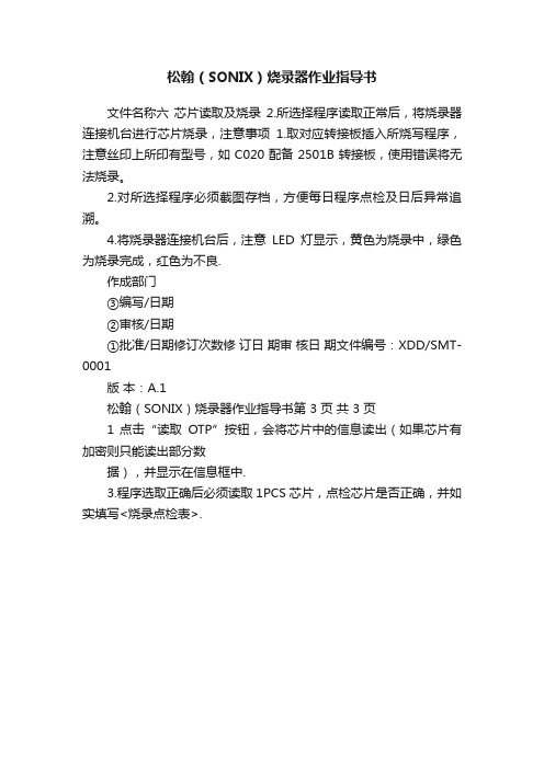
松翰(SONIX)烧录器作业指导书
文件名称六芯片读取及烧录2.所选择程序读取正常后,将烧录器连接机台进行芯片烧录,注意事项1.取对应转接板插入所烧写程序,注意丝印上所印有型号,如C020配备2501B转接板,使用错误将无法烧录。
2.对所选择程序必须截图存档,方便每日程序点检及日后异常追溯。
4.将烧录器连接机台后,注意LED灯显示,黄色为烧录中,绿色为烧录完成,红色为不良.
作成部门
③编写/日期
②审核/日期
①批准/日期修订次数修订日期审核日期文件编号:XDD/SMT-0001
版本:A.1
松翰(SONIX)烧录器作业指导书第 3 页共 3 页
1 点击“读取OTP”按钮,会将芯片中的信息读出(如果芯片有加密则只能读出部分数
据),并显示在信息框中.
3.程序选取正确后必须读取1PCS芯片,点检芯片是否正确,并如实填写<烧录点检表>.。
松翰(SONIX)烧录器作业指导书
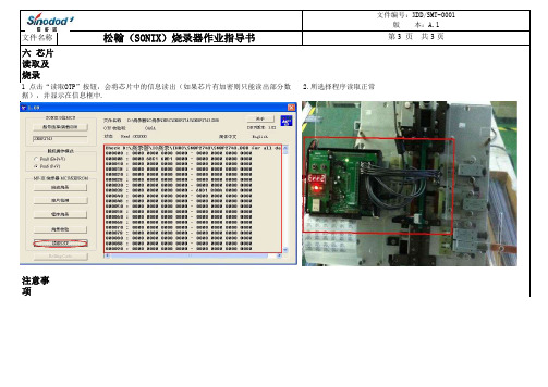
文件名称六 芯片读取及烧录 2.所选择程序读取正常后,将烧录器连接机台进行芯片烧录,注意事项1.取对应转接板插入所烧写程序,注意丝印上所印有型号,如C020配备2501B转接板,使用错误将无法烧录。
2.对所选择程序必须截图存档,方便每日程序点检及日后异常追溯。
4.将烧录器连接机台后,注意LED灯显示,黄色为烧录中,绿色为烧录完成,红色为不良.
作成部门
③编写/日期
②审核/日期
①批准/日期修订次数修 订日 期审 核日 期文件编号:XDD/SMT-0001
版 本:A.1
松翰(SONIX)烧录器作业指导书第 3 页 共 3 页
1 点击“读取OTP”按钮,会将芯片中的信息读出(如果芯片有加密则只能读出部分数
据),并显示在信息框中.
3.程序选取正确后必须读取1PCS芯片,点检芯片是否正确,并如实填写<烧录点检表>.。
SONIX M2IDE中文说明书

M2IDE 用户手册SONiX 8-Bit MCUM2IDE 用户手册Version 1.0SONiX 公司保留对以下所有产品在可靠性、 功能和设计方面的改进做进一步说明的权利。
SONiX 不承担由 本手册所涉及的产品或电路的运用和使用所引起的任何责任。
SONiX 的产品不是专门设计应用于外科植入、生 命维持和任何 SONiX 产品的故障会对个体造成伤害甚至死亡的领域。
如果将 SONiX 的产品应用于上述领域, 即使这些是由 SONiX 在产品设计和制造上的疏忽引起的,用户也应赔偿所有费用、损失、合理的人身伤害或死 亡所直接或间接产生的律师费用, 并且用户保证 SONiX 及其雇员、 子公司、 分支机构和销售商与上述事宜无关。
SONiX TECHNOLOGY CO., LTD.Page 1 of 74Version1.0M2IDE 用户手册修改记录版本 V1.0 时间 2009/8/18 修改说明 初版SONiX TECHNOLOGY CO., LTD.Page 2 of 74Version1.0M2IDE 用户手册目录修改记录 .............................................................................................................................................................................................. 2 目 录 .................................................................................................................................................................................................... 3 第 1 章 系统概要与安装 .................................................................................................................................................................... 5 1.1 M2IDE简介............................................................................................................................................................................ 5 1.2 安装 ....................................................................................................................................................................................... 6 1.2.1 系统配置需求............................................................................................................................................................ 6 1.2.2 硬件安装.................................................................................................................................................................... 6 1.2.3 软件安装.................................................................................................................................................................... 8 第 2 章 视窗界面 .............................................................................................................................................................................. 14 2.1 快速开始 ............................................................................................................................................................................. 14 2.2 菜单—文件/编辑/视图/调试/辅助/窗口/帮助选项 ........................................................................................................... 15 2.2.1 启动M2IDE系统 ..................................................................................................................................................... 15 2.2.2 M2IDE界面 .............................................................................................................................................................. 17 2.2.3 文件菜单(File) ................................................................................................................................................... 20 2.2.4 编辑菜单(Edit) ................................................................................................................................................... 23 2.2.5 视图菜单(View) ................................................................................................................................................. 26 2.2.6 调试菜单(Debug) ............................................................................................................................................... 27 2.2.7 应用菜单(Utility) ............................................................................................................................................... 30 2.2.8 窗口菜单(Window) ............................................................................................................................................ 32 2.2.9 帮助菜单(Help).................................................................................................................................................. 33 2.2.10 窗口管理................................................................................................................................................................ 34 2.3 创建和调试应用程序 ......................................................................................................................................................... 37 2.3.1 创建工程/新建文件................................................................................................................................................. 37 2.3.2 程序的编译和链接.................................................................................................................................................. 42 2.3.3 程序的运行与调试.................................................................................................................................................. 44 2.3.4 编译选项(Code Option选项) ............................................................................................................................. 49 2.3.5 工程文件类型.......................................................................................................................................................... 50 2.4 如何仿真LCD ..................................................................................................................................................................... 51 第 3 章 开发语言 .............................................................................................................................................................................. 52 3.1 指令集 ................................................................................................................................................................................. 52 3.2 伪指令 ................................................................................................................................................................................. 54 3.3 包含文档 ............................................................................................................................................................................. 55 3.4 宏 ......................................................................................................................................................................................... 56 3.5 条件编译控制 ..................................................................................................................................................................... 60 附录 .................................................................................................................................................................................................... 63 附录Ⅰ编译器错误信息说明 .................................................................................................................................................... 63 附录Ⅱ 菜单命令,工具和快捷方式一览表........................................................................................................................... 67 附录Ⅲ 伪指令表 ...................................................................................................................................................................... 70 附录Ⅳ 图片列表 ...................................................................................................................................................................... 71 附录Ⅴ相关FAQ ........................................................................................................................................................................ 73SONiX TECHNOLOGY CO., LTD.Page 3 of 74Version1.0M2IDE 用户手册前言在 SONiX 8 位微控器中,SN8P2XXX 系列开发系统采用的是在线仿真器(ICE),而 PC 机上运行的软件是 M2IDE 或 SN8 C Studio。
SONiX 8 位单片机 初学者必看基础问题点与回复

SONiX 8 位单片机SONIX 公司保留对以下所有产品在可靠性、功能和设计方面的改进做进一步说明的权利。
SONIX 不承担由本手册所涉及的产品或电路的运用和使用所引起的任何责任。
SONIX 的产品不是专门设计应用于外科植入、生命维持和任何SONIX 产品的故障会对个体造成伤害甚至死亡的领域。
如果将SONIX 的产品应用于上述领域,即使这些是由SONIX 在产品设计和制造上的疏忽引起的,用户也应赔偿所有费用、损失、合理的人身伤害或死亡所直接或间接产生的律师费用,并且用户保证SONIX 及其雇员、子公司、分支机构和销售商与上述事宜无关。
目录1系统时钟和工作模式.................................................................................................................................... .. (5)Q1.1 实际芯片应用无法进入“SLEEP MOD E”? (5)Q1.2 采用SN8P2501内部高速RC振荡器工作时,红外解调管没有波形输出 (5)Q1.3 芯片烧录成功后,采用外部振荡器工作频率不正确 (5)Q1.4 系统板采用RC振荡器,如何解决仿真和实际芯片工作的频率误差问题 (5)Q1.5 如何利用仿真器进行RC振荡器的仿真(KERNAL CHIP为S8KD-2)? (5)Q1.6 若3.3V供电,16MHZ出现不稳定现象 (5)Q1.7 用手触摸晶振偶尔有晶振未停振但I/O口无输出现象 (5)Q1.8 使用SN8P1604进入SLEEP时耗电过大 (5)Q1.9 SN8P2501应用内部高速RC振荡计时不准 (6)Q1.10 应用RC振荡时频率应注意哪些问题 (6)Q1.11 内部低速RC振荡频率精度 (6)Q1.12 应用SN8P1708,在进入SLEEP MODE时为什么系统的耗电流高于400U A以上 (6)2 仿真编译CODE OPERA TION设置 (7)Q2.1 怎样选择CODE OPERATION各选项? (7)Q2.2 芯片在烧录时如何加密 (8)Q2.3 客户程序在ICE上可以通过,OTP时有问题 (8)3 中断服务程序.................................................................................................................................... .. (9)Q3.1 如何进入正确的中断服务程序? (9)Q3.2 PUSH和POP指令使用注意事项。
SONiX 8-Bit MCU SN8ICE 2K Plus II 说明书
SONiX 8-Bit MCUSN8ICE 2K Plus II使用说明书V1.0SONiX公司保留对以下所有产品在可靠性、功能和设计方面的改进做进一步说明的权利。
SONiX不承担由本手册所涉及的产品或电路的运用和使用所引起的任何责任。
SONiX的产品不是专门设计应用于外科植入、生命维持和任何SONiX产品的故障会对个体造成伤害甚至死亡的领域。
如果将SONiX的产品应用于上述领域,即使这些是由SONiX在产品设计和制造上的疏忽引起的,用户也应赔偿所有费用、损失、合理的人身伤害或死亡所直接或间接产生的律师费用,并且用户保证SONiX及其雇员、子公司、分支机构和销售商与上述事宜无关。
修正记录版本日期修改内容VER1.0 2009/07 第一版目录目录 (2)1.产品介绍 (3)1.1 产品性能特征 (3)1.2 产品标准配置 (3)2.硬件连接 (4)2.1 硬件产品介绍 (4)2.2 硬件连接步骤 (5)2.3 连接仿真转接板 (6)3.软件安装 (7)3.1 M2IDE 安装步骤 (7)3.2 USB 驱动程序安装 (10)4.使用注意事项 (13)5.简单故障处理方法 (15)6.应用及保修说明 (16)1.产品介绍SN8ICE2K Plus II 是SONiX的新一代开发工具产品,适用于SN8P2000系列8-bit MCU应用的实时硬件仿真,可为项目开发提供一个功能强大且稳定可靠的仿真环境。
本产品具有良好的兼容性和友好的人性化接口,能为新产品的设计提供一个方便的开发平台,具有很好的易用性和易操作性。
1.1 产品性能特征¾双FPGA设计,保证仿真器良好的兼容性和扩充性¾支持SN8P2000系列芯片的实时硬件仿真¾功能丰富的外接接口和扩充接口¾安装软件时自动安装驱动,无需额外手动安装¾采用USB方式与PC沟通传输数据1.2 产品标准配置¾SONiX SN8ICE2K Plus II(1台)¾ DC7.5V/2A 15W电源适配器(1个)¾ B Type USB线(1条)¾产品使用说明书(1份)¾电子配件(1袋),内附适当的短路帽、晶振、振荡匹配电容等¾ 28 Pin(窄)仿真排线(1条)2. 硬件连接2.1 硬件产品介绍仿真介面復位按鍵功能跳針電源指示燈電源開關晶振/電容更換處適配器USB 指示燈图2.1 产品连接示意图¾ 电源开关:打开/关闭SN8ICE2K Plus II 工作电源¾ 电源指示灯:打开SN8ICE2K Plus II 电源时,指示灯点亮显示红色 ¾ USB 指示灯:USB 成功连接后,指示灯显示绿色¾ 晶振与电容更换处: 此缺口用来快速更换适当的晶振与电容值¾功能跳针:z INTERNAL 5V :开/短路跳针,仿真芯片选择使用目标线路板电源/仿真器本身电源图2.2 INTERNAL 5Vz INTERNAL 3.3V:开/短路跳针,仿真芯片选择使用目标线路板电源/仿真器本身电源图2.3 INTERNAL 3.3Vz AVREFH/VDD:AVREFH为仿真芯片ADC线路的参考高电压。
SONIX
4 SN8P2700系列单片机
适用领域
电磁炉、空调、充电器等大、小家电以及各种需要ADC 和高抗干扰性的产品。
1.2.2 引脚排列和说明
1.2.2 引脚排列和说明
1.2.2 引脚排列和说明
1.2.2 引脚排列和说明
1.3SONIX单片机的内部结构
1.3.1 CPU结构
CPU即为中央处理单元,是整个单片机的中枢。由算 术逻辑单元(ALU)、控制单元和专用寄存器组三部 分组成 。
SN8P1604A 4K*16
128
4
- - V 22
1
11
10 SKDIP28/SOP28
1 SN8P1600系列单片机
1)应用特征
最大可达4K*16 ROM 48~128字节RAM 可编程设置上拉电阻的I/O口 内置上电复位、低电压检测电路 内置看门狗定时器 59条简单有效的指令
2)适用领域
2)适用领域
电子秤、血压计等电子测量产品
4 SN8P1900系列单片机
SN8P1900系列单片机是SONIX公司最新推 出的片内带16位ADC、LCD驱动器、高速低 功耗8位单片机。
4 SN8P1900系列单片机
1)应用特性 内置Δ-Σ型16位ADC 内置高速PWM/BUZZER接口 内置高速SIO口 内置4*32 LCD 驱动
ADC、DAC、PWM或BUZZER输出、内置SIO通 讯口、LCD DRIVER、WATCH DOG计时器、内 置LVD 电路。
SONIX单片机命名规则
SN8 X XXXX X X XXX 1 2 345
1:存储器类型: P表示存储器为OTP一次可编程 性 A表示MASK型,即掩模型。
2:型号:SONIX系列命名,用4位表示 3:增强型号:一般后面加字母A 表示增强型。 4:封装形式: Q: QFP P: PDIP K: SKDIP
松翰摄像头烧录工具使用说明
松翰烧录说明
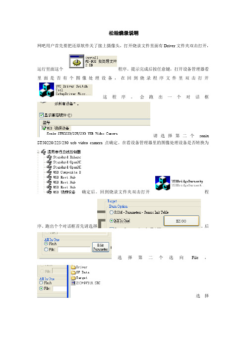
网吧用户首先要把还原软件关了接上摄像头,打开烧录文件里面有Driver文件夹双击打开,
运行里面这个程序。
提示完成后按任意键,打开设备管理器看里面是否有个图像处理设备,在回到烧录程序文件里双击打开
这程序。
会跑出一个对话框
请选择第二个sonix ST50220/225/230 usb video camera 点确定。
在看设备管理器里的图像处理设备是否转换为
确定后。
回到烧录文件夹双击打开程
序。
跑出个个对话框首先请选择。
后
选择第二个选向File,
选择
213+9V111.SEC,然后点
等烧录(烧录过程中不要提示出错,出错了就失败了)完成后退出。
打开
把设备转回USB视频设备。
后重启电脑,打开看是否有图像,有的话就烧录成功,把还原开回去。
SONIX Pm10 产品说明书
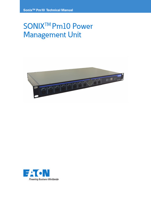
SONIX TM Pm10 Power Management Unit2PA/GA Power Management unitSONIX Pm10 TECHNICAL mANUAL TM365-1 / A June 2022 Contents 1 INTRODUCTION . . . . . . . . . . . . . . . . . . . . . . . . . . . . . . . . . . . . . . . . . . . . . . . . . . . . . . . . . . . . . . . . . . . . . . . .41.1 Eaton quality assurance ......................................................................41.2 About the product ..........................................................................41.3 Key features . (4)2 BEFORE YOU BEGIN . . . . . . . . . . . . . . . . . . . . . . . . . . . . . . . . . . . . . . . . . . . . . . . . . . . . . . . . . . . . . . . . . . . . .42.1 Packaging .................................................................................42.2 Safe working practice .......................................................................42.3 In the box ................................................................................42.4 Required tools .............................................................................42.5 Recommended spares . (4)3 UNIT OVERVIEW . . . . . . . . . . . . . . . . . . . . . . . . . . . . . . . . . . . . . . . . . . . . . . . . . . . . . . . . . . . . . . . . . . . . . . .53.1 Front panel layout ..........................................................................53.2 Rear panel layout ...........................................................................53.3 Specifications .............................................................................53.3.1 Weight and dimensions ...................................................................53.3.2 Power and utility ........................................................................53.3.3 Environmental operating conditions (5)4 INSTALLATION AND CONNECTIVITY . . . . . . . . . . . . . . . . . . . . . . . . . . . . . . . . . . . . . . . . . . . . . . . . . . . . . . .64.1 Physical installation .........................................................................64.2 Power Bus ................................................................................74.3 AC power input ............................................................................94.4 AC power output ...........................................................................74.4.1 Outputs 1 to 8 .........................................................................124.4.2 Auxiliary output ........................................................................134.5 48 V dc power distribution ..................................................................134.6 Fault output ..............................................................................144.7 Fusing . (15)5 SETUP AND CONFIGURATION . . . . . . . . . . . . . . . . . . . . . . . . . . . . . . . . . . . . . . . . . . . . . . . . . . . . . . . . . . .166 UNIT OPERATION . . . . . . . . . . . . . . . . . . . . . . . . . . . . . . . . . . . . . . . . . . . . . . . . . . . . . . . . . . . . . . . . . . . . . .166.1 Power loss protection ......................................................................166.2 AC Power input status indication. . . . . . . . . . . . . . . . . . . . . . . . . . . . . . . . . . . . . . . . . . . . . . . . . . . . . . . . . . . . . .166.3 Power Outputs indication ...................................................................166.4 Auxiliary Output ...........................................................................166.5 DC Rack Output ..........................................................................166.6 Front panel button operation .................................................................176.7 Front panel display. . . . . . . . . . . . . . . . . . . . . . . . . . . . . . . . . . . . . . . . . . . . . . . . . . . . . . . . . . . . . . . . . . . . . . . . .177 UNIT CUSTOMISATION . . . . . . . . . . . . . . . . . . . . . . . . . . . . . . . . . . . . . . . . . . . . . . . . . . . . . . . . . . . . . . . . .178 COMMISSIONING/TESTING . . . . . . . . . . . . . . . . . . . . . . . . . . . . . . . . . . . . . . . . . . . . . . . . . . . . . . . . . . . . .179 MAINTENANCE . . . . . . . . . . . . . . . . . . . . . . . . . . . . . . . . . . . . . . . . . . . . . . . . . . . . . . . . . . . . . . . . . . . . . . .183PA/GA Power Management unitSONIX Pm10 TECHNICAL mANUAL TM365-1 / A June 2022 1.1 List of FiguresFIGURE 1 . GENERAL, SIMPLIFIED VIEW OF THE SONIX PM10 FRONT PANEL . . . . . . . . . . . . . . . . . . . . . . . . . . . . . . . . .8FIGURE 2 . GENERAL, SIMPLIFIED VIEW OF THE SONIX PM10 REAR PANEL . . . . . . . . . . . . . . . . . . . . . . . . . . . . . . . . . . .8FIGURE 3 . STACKING PM10 WITH OTHER SONIX UNITS . . . . . . . . . . . . . . . . . . . . . . . . . . . . . . . . . . . . . . . . . . . . . . . . . .10FIGURE 8 . PM10 POWERED FROM TWO REDUNDANT POWER SUPPLIES . . . . . . . . . . . . . . . . . . . . . . . . . . . . . . . . . . .11FIGURE 9 . PM10 POWERED FROM A SINGLE POWER SUPPL Y . . . . . . . . . . . . . . . . . . . . . . . . . . . . . . . . . . . . . . . . . . . . .12FIGURE 10 . CONNECTING SONIX 350-D TO THE OUTPUTS . . . . . . . . . . . . . . . . . . . . . . . . . . . . . . . . . . . . . . . . . . . . . . .13FIGURE 11 . AUXILIARY OUTPUT . . . . . . . . . . . . . . . . . . . . . . . . . . . . . . . . . . . . . . . . . . . . . . . . . . . . . . . . . . . . . . . . . . . . .13FIGURE 12 . 48 V DC POWER DISTRIBUTION BETWEEN TWO PM10 UNITS . . . . . . . . . . . . . . . . . . . . . . . . . . . . . . . . . . .14FIGURE 13 . FAULT OUTPUT . . . . . . . . . . . . . . . . . . . . . . . . . . . . . . . . . . . . . . . . . . . . . . . . . . . . . . . . . . . . . . . . . . . . . . . . . .15List of TablesTABLE 1 . FRONT PANEL INDICATORS AND SWITCHES . . . . . . . . . . . . . . . . . . . . . . . . . . . . . . . . . . . . . . . . . . . . . . . . . . . .8TABLE 2 . REAR PANEL CONNECTIONS . . . . . . . . . . . . . . . . . . . . . . . . . . . . . . . . . . . . . . . . . . . . . . . . . . . . . . . . . . . . . . . . .8TABLE 3 . FAULT OUTPUT STATES . . . . . . . . . . . . . . . . . . . . . . . . . . . . . . . . . . . . . . . . . . . . . . . . . . . . . . . . . . . . . . . . . . . .15TABLE 5 . FRONT PANEL POWER INPUT STATUS INDICATORS . . . . . . . . . . . . . . . . . . . . . . . . . . . . . . . . . . . . . . . . . . . . .16TABLE 6 . FRONT PANEL POWER OUTPUTS STATUS INDICATORS . . . . . . . . . . . . . . . . . . . . . . . . . . . . . . . . . . . . . . . . . .16TABLE 9 . FRONT PANEL DC RACK OUTPUT STATUS INDICATORS . . . . . . . . . . . . . . . . . . . . . . . . . . . . . . . . . . . . . . . . .17TABLE 10 . MEASUREMENT INDICATION LED . . . . . . . . . . . . . . . . . . . . . . . . . . . . . . . . . . . . . . . . . . . . . . . . . . . . . . . . . .174PA/GA Power Management unitSONIX Pm10 TECHNICAL mANUAL TM365-1 / A June 2022 1 Introduction These instructions are intended for all users who will have to install, commission, configure and setup the Sonix Pm10 power management unit. It is assumed that you have necessary electrical, electronic and telecommunications experience to undertake the work. If in doubt, please speak to your local Eaton representative.1.1 Eaton quality assuranceEaton design, manufacture, installs and commission all our products to the highest standards of quality. This quality process is embraced and adopted throughout the group in all areas of our operations.This is demonstrated by our compliance and strict adherence to ISO 9001, 14001, ATEX, IECEX policies. On receipt of the product, ensure that the cartons are undamaged and that the contents are all correct and complete.Should this product reach you in an unsatisfactory condition please report this to Eaton to enable us to rectify and investigate the fault in a speedy manner.1.2 About the productSonix Pm10 is a compact 19” 1U design unit, housing the circuitry for power distribution, switchover andmanagement for the Sonix PA/GA system components. Output power is individually protected, monitored and efficiently and securely distributed between eight main AC outputs, one auxiliary AC output and one 48 V DC output, providing all PA/GA system power needs in a single and compact enclosure.For high criticality systems that require duplicated AC power inputs, Sonix Pm10 ensures that PA/GA system is always operational and in the event of site supply failure or dangerous fluctuations, the system will automatically switch over to the standby power supply. Even under full load operation, this is achieved without any disruption to the system operation, continuously advising the unit status via comprehensive unit display.Input and output power connections to the Pm10 unit is via shake proof plug and socket, ensuring simple and speedy connectivity of the unit and ease of maintenance.1.3 Key featuresSonix Pm10 is designed to provide the following features:• Highly efficient 1U package • 110 / 230 V ac compatible •8 outputs• 48 V dc output• High integrity power supply and cable monitoring • Failsafe rapid dual supply switchover• Voltage and current monitoring / indication•Visual status indication and remote fault reporting2 Before you begin2.1 PackagingIn the interest of preserving the environment, Eaton aims to use recycled packaging wherever practical. Due to the physical nature of our products, we provide adequate packaging to protect the goods during transit. Please ensure that once unpacked, checked and installed that all packaging is disposed of or recycled in a responsible manner.2.2 Safe working practiceWhilst working on or within the Sonix PA/GA system it is our prime interest that you remain safe throughout. During this work you may be exposed to potentially hazardous voltages, currents, confined spaces and potentially hazardous industrial environments. Prior to undertaking any work please ensure relevant permits and regulations are adhered to.2.3 In the box• 1 x Sonix Pm10 unit.•1 x Technical Manual2.4 Required tools• Flat blade screw driver (0.6x3.5) – for plug wiring.•Appropriate screw driver for cage-nut fixings.2.5 Recommended sparesUser replaceable fuses:• Eaton Bussmann Time delay 2A S505-2R •Eaton Bussmann Time delay 4A S505-4R5PA/GA Power Management unit3 Unit overview3.1 Front panel layout6PA/GA Power Management unitSONIX Pm10 TECHNICAL mANUAL TM365-1 / A June 2022 can be either M5 or M6 fitted through four mounting it will require to be installed on shelves or other weightA – Rack frame – 19”B – Additional Sonix PA/GA unitsC – Unit fixingsD – Shelf or other weight support structure. Compulsory for units supporting amplifiers.Figure 3. Stacking Pm10 with other Sonix units.ote: N Recommended fixing screw length is 16 mm, complete with washers.Warning: Ensure that no ventilation points are obstructed, and that the module is correctly supported within the cabinet.IEC 60417-6043 (2011=01)Beware of sharp edges and corners!Take care while handling.7PA/GA Power Management unitSONIX Pm10 TECHNICAL mANUAL TM365-1 / A June 2022 4.2 AC power inputWarning: High voltages present. Isolate power supply elsewhere before connecting the unit.Warning: Unit MUST be earthed via AC PowerEach individual Pm10 unit is powered by either one or two redundant ac power sources connected to Primary and Secondary power inputs. In both cases, the incoming power feed must be protected by at least one 32 A RCBO, as per diagrams below.Incoming power supply110 V ac 230 V acFigure 8. Pm10 powered from two redundant power supplies.8PA/GA Power Management unitSONIX Pm10 TECHNICAL mANUAL TM365-1 / A June 2022 The Pm10 unit will instantly and reliably switch between the primary and secondary power inputs.Although it is possible for power supplies to vary between primary and secondary inputs (i.e. 110 V ac on primary and 230 V ac on secondary), that confi guration is not recommended due to the need for de-rating of 350-d units present in the system – see 350-d Technical Manual for more details.Warning: Minimum required wire diameter forboth Primary and Secondary input is 4 mm 2. Power cable must include an adequately sized Earth conductor, connected to protective earth.ote: N As these cables are power feeds, they should be, wherepossible, routed within the PA/GA system in a separate way to avoid contact with dc power or audio cables and reduce the possibility of interference.Maximum supported wire diameters for both primary and secondary plugs are:• Solid: up to 16 mm 2•Stranded:• including sleeved ferrule: up to 10 mm 2• including non-sleeved ferrule: up to 16 mm 2•Connection method: Push-in spring connection •Stripping length: 18 mmWarning: Non-solid cables MUST be ferruleddue to use of spring-clamp retaining mechanism.Warning: Observe the polarity / order of connections.Incoming power supply110 V ac 230 V acFigure 9. Pm10 powered from a single power supply.9SONIX Pm10 TECHNICAL mANUAL TM365-1 / A June 2022 10PA/GA Power Management unitSONIX Pm10 TECHNICAL mANUAL TM365-1 / A June 2022 4.4 48 V dc power distribution48 V dc power is generated internally by an ac to dc power supply, switched live between the power inputs. The output voltage is regulated to +/- 0.5% and is used for all PA/GA system dc power needs. Total load should not exceed 95W.Current limit for individual 48 V dc output is 2 A,protected by replaceable fuse located on the front panel (see Figure 1).When more than one Pm10 unit is being used in the system, their 48 V dc rail can be shared between the units. To achieve this, the Pm10 units DC outputs are daisy-chained: 48 V dc output of the first unit isconnected to 48 V dc input of the next unit, with no limit on how many units can be chained. The 48 V dc output from the last unit is then used as a primary power source for PA/GA 48 V dc with the others providing a redundant supply .Warning: If utilising the 48 V output in user touchable equipment an isolating DC:DC power supply is required.Figure 12. 48 V dc power distribution between two Pm10 units.ote: N These cables are power feeds. They should be, wherepossible, routed within the PA/GA system in a separate way to avoid contact with ac power or audio cables and reduce the possibility of interference.Maximum supported wires are:• Solid: 1.5 mm 2•Stranded:• including sleeved ferrule: 0.5 mm 2• including non-sleeved ferrule: 1.5 mm 211PA/GA Power Management unitSONIX Pm10 TECHNICAL mANUAL TM365-1 / A June 2022 4.5 RJ45 Power BusThe Power bus connections are reserved for future expansion.4.7 Fault outputThe fault output on the Sonix Pm10 is a volt-free contact output. The state of the fault output is determined byhealth of the AC inputs to the unit:T able 3. Fault output states.Fault output will hold its state for approximately 10 seconds before clearing after any fault has cleared, to allow any transient faults to be registered by any external monitoring.ote: N There is no configuration option to change the sense of the output.Maximum cable section supported are:• Solid: 1.5 mm 2•Stranded:• including sleeved ferrule: 0.5 mm 2• including non-sleeved ferrule: 1.5 mm 24.8 FusingIn addition to the set of external fuses for outputprotection, the Sonix Pm10 is equipped with two internal fuses to protect the unit itself:12PA/GA Power Management unitSONIX Pm10 TECHNICAL mANUAL TM365-1 / A June 2022 5 Setup and Configuration Sonix Pm10 unit does not have any external switches nor jumper links to set.All units come pre-configured with a general setup to support a secondary input but prefer primary. If a different configuration is required, please contact your local Eaton representative.6 Unit operation6.1 Power loss protectionWhen the Sonix Pm10 unit detects an AC power loss on the active input, it will immediately begin swapping all the outputs to use a redundant AC input, if available. When a preferred input becomes available again, the unit will wait for at least 10 seconds before swapping back. This delay is intended to allow the input tostabilise, to avoid switching during surges from other loads and to ensure the supply will remain available and will not immediately fail again.ote: N There will be a finite gap in supply power while the unit is carefully switching inputs, this is to ensure that the two supplies are not connected together.ote: N Output voltage is dependent on which input is currently selected. All outputs will have the same source.6.3 AC Power input status indicationPm10 reports the status of its AC power inputs via pairs of green and red LEDs grouped with each input (seeFigure 1), as per table below:T able 4. Front panel power input status indicators.6.3 Power Outputs indicationPm10 reports the status of its outputs via pairs of green and red LEDs grouped with each output (see Figure 1),as per table below:T able 5. Front panel power outputs status indicators.Fuse monitoring for Pm10’s individual outputs can be disabled in the configuration via SAS (please refer to SAS Product Manual for details). The unit will still be protected, but the status of the output(s) will not be reported.6.4 Auxiliary OutputWarning: High voltages present. Power down Pm10 unit before connecting or disconnecting this output.This output is available as a reliable AC power source for other equipment in the PA/GA rack, for example fans and air conditioning.Warning: Observe load limit of 4 A on unit and avoid connecting items with high inductive loads. These typically have high surge currents.6.5 DC Rack OutputThis is a regulated 48 V dc output, dedicated as a power source for other Sonix units that are dc powered, such as Hmi or Vw2.Pm10 reports the status of its DC Rack Output via pairof green and red LEDs (see Figure 1), as per table below:T able 6. Front panel dc rack output status indicators.6.6 Front panel button operationThe Sonix Pm10’s front panel button has three functions:1. Selecting measurements – each short press toggles between Voltage and Current measurements and presents the result on the front panel display (see Figure 1).2 Initiate local fault reset – long-press of the button will reset all fault flags on the unit. If the fault is still present, it will get reintroduced after few seconds.13PA/GA Power Management unitSONIX Pm10 TECHNICAL mANUAL TM365-1 / A June 2022 6.7 Front panel displaySonix Pm10 is equipped with front panel display to show life-time measurements of input supply voltage and overall current. Green LED indicates the currentoperation, as per table below:T able 7. Measurement indication LEDote: N The display is not calibrated and serves only as an indication. Measurements for maintenance and fault-finding purposes need to be taken with calibrated equipment.7 Unit customisationIndividual unit customisation is not available for this unit.8 Commissioning/testingBefore starting commissioning or testing, check that:• Unit is correctly earthed,•Connection of each cable to and from the system is correct and the cables are not damaged,• DC input and output ports have the correct polarity,•There are no short circuits between negative and positive conductors,• Each input is fed via a suitably rated RCBO,•Live and Neutral are correctly connected to the relevant inputs.9 MaintenanceWarning: High voltages present. Power off the system and isolate power input supply before proceeding.Although the Sonix Pm10 unit does not require anyspecific maintenance, the following program represents the minimum care and it is advisable that it will be performed monthly:•Check the unit for visible damage (scratches or bumps).• Check unit fixing to the rack – tighten loose screws.•Check connections and cable integrity - replace damaged cables and push in loosened plugs.•Remove dust and dirt from front panel - clean with a dry cloth.ote: N Do not use sharp objects. Do not use water, aggressive cleaning agents or solvent to clean the unit.All specifications, dimensions, weights and tolerances are nominal (typical) and Eaton reserve the right to vary all data without prior notice.No liability is accepted for any consequence of use.EatonUnit B, Sutton Parkway Oddicroft Lane Sutton in Ashfield United Kingdom NG17 5FBT : +44 (0) 1623 444 /hac *******************© 2022 EatonAll Rights Reserved Printed in UK PublicationNo.TM365-1 / A June 2022Eaton and SONIX™ are registered trademarks.All other trademarks are property of their respective owners.Changes to the products, to the information contained in thisdocument, and to prices are reserved; so are errors and omissions. Only order confirmations and technical documentation by Eaton is binding. Photos and pictures also do not warrant a specific layout or functionality. Their use in whatever form is subject to prior approval by Eaton. The same applies to Trademarks (especially Eaton, Moeller, and Cutler-Hammer). The Terms and Conditions of Eaton apply, as referenced on Eaton Internet pages and Eaton order confirmations.。
sonix烧录器培训资料

sonix烧录器培训资料Sonix烧录器是一种通用的烧录器,它支持多种芯片类型,包括Flash、EEPROM、SRAM等。
它可以通过USB接口与计算机连接,使用户能够轻松地将程序代码烧录到芯片中。
Sonix烧录器具有高速、稳定、可靠的特点,适用于开发板、单片机、嵌入式系统等领域。
Sonix烧录器的工作原理是通过USB接口与计算机通信,接收计算机发送的烧录指令和数据,并将其转换为芯片能够识别的电信号,然后将电信号传输到芯片中实现烧录。
同时,Sonix烧录器还可以从芯片中读取数据,并将其传输到计算机中进行分析和处理。
将Sonix烧录器通过USB接口连接到计算机上,然后打开电源开关。
此时,计算机将会自动识别Sonix烧录器,并安装驱动程序。
在Sonix烧录器的操作界面中选择需要烧录的芯片类型。
在选择芯片类型时,需要提供芯片的型号、厂商等信息。
在计算机上打开相应的编程软件,将要烧录的程序代码加载到计算机中。
在加载程序代码时,需要注意程序代码的格式和编译选项是否与芯片兼容。
在Sonix烧录器的操作界面中选择需要烧录的芯片型号和端口号,然后单击“开始烧录”按钮。
此时,Sonix烧录器将会将程序代码烧录到芯片中。
在烧录过程中,需要注意观察烧录进度和状态信息。
在烧录完成后,可以使用Sonix烧录器读取芯片中的数据。
在读取数据时,需要注意数据的格式和解析方式是否正确。
蛋鸡养殖业是一个具有巨大潜力的行业,随着消费者对高品质鸡蛋的需求不断增加,蛋鸡养殖业也在不断发展和壮大。
为了提高蛋鸡养殖的产量和品质,许多养殖户会参加蛋鸡培训课程。
本文将介绍一些蛋鸡培训资料,帮助养殖户更好地了解蛋鸡养殖技术。
选择适合当地气候、土壤条件的蛋鸡品种是养殖成功的关键。
不同品种的蛋鸡对饲料、管理、疾病抵抗力等方面都有所不同。
因此,养殖户需要根据当地的气候、市场需求以及自己的实际情况选择合适的蛋鸡品种。
蛋鸡需要摄取足够的营养才能正常生长和产蛋。
SONiX 8-Bit MCU Smart Development Adapter 说明书
SONiX 8-Bit MCUSmart Development Adapter使用手冊Version 1.1S O N i X 8-B i t M i c r o -C o n t r o l l e rSONiX 公司保留對以下所有產品在可靠性、功能和設計方面的改進做進一步說明的權利。
SONiX 不承擔由本手冊所涉及 的產品或電路的運用和使用所引起的任何責任。
SONiX 的產品不是專門設計應用於外科植入、生命維持和任何SONiX 產 品的故障會對個體造成傷害甚至死亡的領域。
如果將SONiX 的產品應用於上述領域,即使這些是由SONiX 在產品設計和 製造上的疏忽引起的,用戶也應賠償所有費用、損失、合理的人身傷害或死亡所直接或間接產生的律師費用,並且用戶保 證SONiX 及其雇員、子公司、分支機搆和銷售商與上述事宜無關。
www.a v a n t c o m.c om .t wt K _ày Ñb €修改紀錄版本 日期 說明VER 1.0 2009.10 第一版。
VER1.12010.21. 添加目標板電源說明;2. 更新SDA 圖片及排線腳位元說明;3. 添加SN8 C Studio 軟體安裝資訊。
www.a v a n t c o m.c om .t wt K _ày Ñb €目 錄修改紀錄................................................................................................................................................................................2 1 產品介紹 (4)1.1 性能特點..........................................................................................................................................................................4 1.2 外觀簡介.. (4)2 如何安裝.................................................................................................................................................................................5 2.1 硬體安裝.. (5)2.2 軟體安裝..........................................................................................................................................................................6 3 開始偵錯功能.........................................................................................................................................................................7 3.1 操作步驟..........................................................................................................................................................................7 4 DOWNLOAD SN8功能.......................................................................................................................................................11 4.1 功能說明 (11)4.2 操作步驟........................................................................................................................................................................11 5 注意事項...............................................................................................................................................................................13 5.1 使用限制........................................................................................................................................................................13 5.2 故障排除 (13)www.a va n t c o m.c om .t wt K _ày Ñb €PC 與Target Board 裝置之間溝通的介面,並且可進板需在與SDA 連接正確後再接通電源,請參閱圖2-2 硬體安裝流程圖。
SONIX单片机培训教材2
松翰科技股份有限公司 SONiX TECHNOLOGY CO., LTD
目
录
第1章 I/O 端口.......................................................................................................................................................5 §1.1概 述 ...................................................................................................................................................................5 §1.2基本结构及相关寄存器 ..........................................................................................................................................6 1.2.1 I/O 端口的基本结构.......................................................................................................................................6 1.2.2 I/O 端口的相关寄存器 ..................................................................
SONiX SN8P2501B 用户说明书
SONiX 公司保留对以下所有产品在可靠性,功能和设计方面的改进作进一步说明的权利。
SONiX 不承担由本手册所涉及的产品或电路的运用和使用所引起的任何责任,SONiX 的产品不是专门设计来应用于外科植入、生命维持和任何SONiX 产品的故障会对个体造成伤害甚至死亡的领域。
如果将SONiX 的产品应用于上述领域,即使这些是由SONiX 在产品设计和制造上的疏忽引起的,用户应赔偿所有费用、损失、合理的人身伤害或死亡所直接或间接产生的律师费用,并且用户保证SONiX 及其雇员、子公司、分支机构和销售商与上述事宜无关。
修正记录版本日期内容VER 1.0 2006年12月 1. 初版。
目 录修正记录 (2)目录 (3)11产品概述 (5)1.1 特性 (5)1.2 系统结构框图 (6)1.3 引脚配置 (7)1.4 引脚功能说明 (8)1.5 引脚电路框图 (9)22中央处理器 (CPU) (10)2.1 存储器 (10)2.1.1 程序存储器 (ROM) (10)2.1.1.1 复位向量(0000H) (11)2.1.1.2 中断向量(0008H) (12)2.1.1.3 查表 (13)2.1.1.4 跳转表 (15)2.1.1.5 CHECKSUM计算 (17)2.1.2 编译选项列表 (18)2.1.3 数据存储器(RAM) (19)2.1.4 系统寄存器 (20)2.1.4.1 系统寄存器表 (20)2.1.4.2 系统寄存器说明 (20)2.1.4.3 系统寄存器位定义 (21)2.1.4.4 累加器 (22)2.1.4.5 程序状态寄存器PFLAG (23)2.1.4.6 程序计数器 (24)Z寄存器 (26)2.1.4.7 Y,2.1.4.8 R寄存器 (26)2.2 寻址模式 (27)2.2.1 立即寻址 (27)2.2.2 直接寻址 (27)2.2.3 间接寻址 (27)2.3 堆栈 (28)2.3.1 概述 (28)2.3.2 堆栈寄存器 (29)2.3.3 堆栈操作举例 (30)33复位 (31)3.1 概述 (31)3.2 上电复位 (32)3.3 看门狗复位 (32)3.4 掉电复位 (33)3.4.1 概述 (33)3.4.2 系统工作电压 (33)3.4.3 掉电复位性能改进 (34)3.5 外部复位 (36)3.6 外部复位电路 (37)3.6.1 RC复位电路 (37)3.6.2 二极管&RC复位电路 (37)3.6.3 齐纳二极管复位电路 (38)3.6.4 电压偏置复位电路 (38)3.6.5 外部IC复位 (39)44系统时钟 (40)4.1 概述 (40)4.2 时钟框图 (40)4.3 OSCM寄存器 (41)4.4 系统高速时钟 (42)4.4.1 内部高速RC振荡器 (42)4.4.2 外部高速时钟 (43)4.4.2.1 石英/陶瓷振荡器 (43)4.4.2.2 RC振荡器 (44)4.4.2.3 外部时钟源 (44)4.5 系统低速时钟 (45)4.5.1 系统时钟测试 (45)55系统工作模式 (46)5.1 概述 (46)5.2 模式切换举例 (47)5.3 唤醒时间 (48)5.3.1 概述 (48)5.3.2 唤醒时间 (48)5.3.3 P1W唤醒控制寄存器 (48)66中断 (49)6.1 概述 (49)6.2 中断请求使能寄存器INTEN (49)6.3 中断请求寄存器INTRQ (50)6.4 GIE全局中断 (50)6.5 PUSH,POP处理 (51)6.6 INT0(P0.0)中断 (52)6.7 T0中断 (53)6.8 TC0中断 (54)6.9 多中断操作举例 (55)77定时器 (56)7.1 看门狗定时器 (56)7.2 定时器T0 (57)7.2.1 概述 (57)7.2.2 模式寄存器T0M (58)7.2.3 计数寄存器T0C (59)7.2.4 T0操作时序 (60)7.3 定时/计数器TC0 (61)7.3.1 概述 (61)7.3.2 模式寄存器TC0M (62)7.3.3 计数寄存器TC0C (63)7.3.4 自动重载寄存器TC0R (64)7.3.5 TC0时钟频率输出(蜂鸣器输出) (65)7.3.6 TC0操作举例 (66)7.4 PWM0 (67)7.4.1 概述 (67)7.4.2 TC0IRQ和PWM输出占空比 (68)7.4.3 PWM输出占空比与TC0R的变化 (69)7.4.4 PWM编程举例 (70)88 I/O端口 (71)8.1 I/O端口模式 (71)8.2 I/O口上拉电阻 (72)8.3 I/O漏极开路寄存器 (73)8.4 I/O口数据寄存器 (74)99指令表 (75)1100电气特性 (75)1111 OTP烧录引脚 (77)11.1 转接板插座对应的引脚分布图 (77)11.2 烧录引脚分布图 (78)1122 SN8P2501A升级为SN8P2501B注意事项 (79)1133封装信息 (81)13.1 P-DIP14PIN (81)13.2 SOP14PIN (82)13.3 SSOP16PIN (83)产品概述1.1 特性♦ 存储器 ♦三个中断源 OTP ROM :1K * 16 bits 两个内部中断源:T0, TC0 RAM :48 * 8 bits 一个外部中断源:INT0 四层堆栈缓存器 ♦两个8-bit 定时/计数器♦ I/O 端口 T0:0.5sec RTC 基本定时器 输入输出端口:P0, P1, P2, P5 TC0:自动重新加载定时器/计数器/蜂鸣器输出 输入端:P1.1 可编程漏极开路:P1.0 ♦内置看门狗定时器和内部时钟源 唤醒功能:P0, P1电平变缓触发 低速RC (16KHz @3V, 32KHz @5V). 带上拉电阻:P0, P1, P2, P5外部中断信号触发沿:寄存器PEDGE 控制的P0.0♦双时钟系统 外部高速时钟:RC 模式高达10MHz 外部高速时钟:晶振模式高达16MHz♦ 3-Level LVD内部高速时钟:16MHz RC 复位及电源监控系统 内部低速时钟:16KHz(3V), 32KHz(5V) RC♦ 强大的指令系统♦工作模式 单时钟指令周期 (1T) 普通模式:高、低速时钟同时工作 大部分指令仅需一个周期 低速模式:低速时钟有效 JMP 指令可以在整个ROM 区执行 睡眠模式:高、低速时钟都停止工作 CALL 指令可寻址全部ROM 区 绿色模式:由T0周期性的唤醒 查表功能 (MOVC)可用于全部ROM 区 ♦封装 PDIP 14 pins SOP 14 pins SSOP 16 pins) 特性选择列表定时器 芯片 ROM (word) RAM (Byte) 堆栈 T0 TC0 LVD层数 IHRC I/O 绿色模式低速模式PWM 蜂鸣器唤醒功能的 引脚个数封装SN8P2501A 1K 48 4 V V 1 V 12V V V 5 DIP14/SOP14/SSOP16SN8P2501B 1K 48 4 V V 3 V 12V V V 5 DIP14/SOP14/SSOP161.2 系统结构框图1.3 引脚配置SN8P2501BP (P-DIP 14 pins)SN8P2501BS (SOP 14 pins)SN8P2501BX (SSOP 16 pins)P2.2 1 U 14P2.3P2.1 2 13P2.4P2.0 3 12P2.5VDD 4 11VSSP1.3/XIN 5 10P0.0/INT0P1.2/XOUT 6 9 P1.0P1.1/RST/VPP7 8 P5.4/BZ0/PWM0SN8P2501BPSN8P2501BSP2.2 1 U 16P2.3P2.1 2 15P2.4P2.0 3 14P2.5VDD 4 13VSSVDD 5 12VSSP1.3/XIN 6 11P0.0/INT0P1.2/XOUT7 10P1.0P1.1/RST/VPP8 9 P5.4/BZ0/PWM0SN8P2501BX1.4 引脚功能说明引脚 类型 说明VDD, VSSP数字电路电源输入端P1.1/RST/VPP I, P P1.1:禁止外部复位的情况下仅作输入引脚 (施密特触发器) P1.1无内置上拉电阻;具有唤醒功能;RST :系统复位输入引脚,施密特触发器结构,低电平触发,一般处于高电平状态 VPP :OTP 烧录引脚P1.3/XIN I/OP1.3输入/输出引脚,输入时为施密特触发器结构; 内置上拉电阻;具有唤醒功能;XIN :外部振荡器(晶振或RC )有效时作为振荡器输入引脚 P1.2/XOUT I/OP1.2输入/输出引脚,输入引脚为施密特触发器结构 内置上拉电阻;唤醒功能;XOUT :外部晶振模式时作为振荡器输出引脚P0.0/INT0 I/O P0.0输入/输出引脚,输入引脚为施密特触发器结构; 内置上拉电阻;具有唤醒功能;INT0 触发引脚(施密特触发器); TC0 事件计数器时钟输入引脚;P1.0 I/OPP1.0输入/输出引脚,漏极开路输入引脚为施密特触发器结构;内置上拉电阻;P2 [5:0] I/O输入/输出引脚,输入引脚为施密特触发器结构;内置上拉电阻;P5.4/BZ0.PWM0 I/O P5.4输入/输出引脚,输入引脚为施密特触发器结构;内置上拉电阻;TC0 2分频输出引脚,PWM 和蜂鸣器引脚;1.5 引脚电路框图Port 0, 2, 5Port 1.0Port 1.2, 1.3Port 1.1Ext. Reset中央处理器 (CPU)2.1 存储器2.1.1 程序存储器 (ROM)) 1 words ROMROM0000H 复位向量用户复位向量跳至用户程序初始端0001H.. 0007H 通用区域0008H 中断向量 用户中断向量 0009H 用户程序. . 000FH 0010H 0011H. . . . . 03FCH 通用区域用户程序结束03FDH03FEH03FFH 系统保留2.1.1.1 复位向量(0000H)一个字长的系统复位向量。
松翰芯片指令集

1.算术指令
内容
功能
影响标记
功效
ADC A, M
A <- A + M + C
C DC Z
带进位加
ADC M, A
M <- Aห้องสมุดไป่ตู้+ M + C
C DC Z
带进位加存入M
ADD A, M
A <- A + M
C DC Z
A与存储器相加
ADD M, A
M <- A + M
C DC Z
A +存储器存入M
4.处理指令
内容
功能
影响标记
功效
SWAP M
与A半字节交换
SWAPM M
与M半字节交换
RRC M
A <- RRC M
C
M右移一位存入A
RRCM M
M <- RRC M
C
M右移一位存入M
RLC M
A <- RLC M
C
M左移一位存入A
RLCM M
M <- RLC M
C
M左移一位存入M
CLR M
M <- 0
B0ADD M, A
M(B0) <- M(B0) + A
C DC Z
A + M(0组)存入
ADD A, I
A <- A + I
C DC Z
A +立即数存入A
SBC A, M
A <- A - M - /C
C DC Z
带进位减
SBC M, A
M <- A–M - /C
SONIX使用说明以及注意事项

SONIX的使用说明以及注意事项韩国SONIC WORLD研发的SONIX音波动全身运动机是利用索尼克世界独有电磁器技术与音响扬声器而制造的,它与传统的全身运动机不同,不是以快速旋转产生复合型振动,而是利用电磁器技术与扬声器原理,产生超低频率的声波,传达给人体的尖端科学。
它解决了电机方式所带的噪音、磨损等问题,是世界首个优化利用振动运动原理的产品。
SONIX的装箱清单一般包括主机、机身和机板,另外还有一些小零件:电源线1条、遥控器1个、音箱连接线1条、“T”型扳子1个、扳子螺栓8个、调节水平垫3个、使用说明书1本。
检查完清单之后,就可以安装了,安装过程中需要注意以下事项:1、不得装在湿气多的地方或者安装在有可能与水分接触的阳台附近;2、安装产品时,应与墙面有20cm以上的距离;3、应安装在既坚固又水平的地方;4、需检查产品表面表示的最大电子容量和使用的插座的电子容量是否充足;5、搬运产品时,应使用搬运专用工具,随意搬运会损坏产品。
正确安装完毕之后就可以放心使用了,但在使用过程中也需要注意以下事项:1、不稳定的姿势时使用运动器,或者突然运动时,会给身体带来负担,所以在正确姿势下,按开始按钮;2、运动器在起动时,从运动器上离开,会有危险,因此必须先按停止按钮,确认该运动器完全被停止后,再离开运动器;3、为防止浪费耗电,不使用机器时,请将电源线拔掉;4、起动产品时,在机板上蹦跳,会造成人身伤害;5、老年人或儿童使用本产品时,需保护人看护及留意;6、预防产品的破损或操作错误,不得随意拆卸,随意修理,改造产品。
维护和保管方法:1、不可在产品附件放置引火物质;2、不可向机器直接喷洒水分或用纯苯、稀释剂、消毒剂来清洁产品;3、清洁产品前,必须将电源插拔掉;4、清洁时,不可让水进入机器内部,用干布擦拭产品;5、清洁产品外壳时,应使用合适产品材质的清洁剂;6、长时间不使用产品时,应清洁产品外壳及干燥后再进行保管。
- 1、下载文档前请自行甄别文档内容的完整性,平台不提供额外的编辑、内容补充、找答案等附加服务。
- 2、"仅部分预览"的文档,不可在线预览部分如存在完整性等问题,可反馈申请退款(可完整预览的文档不适用该条件!)。
- 3、如文档侵犯您的权益,请联系客服反馈,我们会尽快为您处理(人工客服工作时间:9:00-18:30)。
算术指令 .............................................................................................................................................................. 8 ADC—带进位加法运算 ................................................................................................................................8 ADD—不带进位的加法运算 ......................................................................................................................... 8 B0ADD—累加器和存储器 BANK0 内容相加................................................................................................9 SBC—带借位减法........................................................................................................................................9 SUB—不带借位减法 ..................................................................................................................................10
SONiX TECHNOLOGY CO., LTD
-2-
RevБайду номын сангаасsion 1.93
SONiX 8-Bit MCU
INSTRUCTION SET
目录
1 概述 .............................................................................................................................................................. 4 2 指令表........................................................................................................................................................... 5 3 指令说明 ....................................................................................................................................................... 6
SONiX 8 位 MCU
指令集
SONiX 8-Bit MCU
INSTRUCTION SET
SONiX 8 位单片机
SONIX 公司保留对以下所有产品在可靠性、功能和设计方面的改进做进一步说明的权利。SONIX 不承担由本手 册所涉及产品或电路的运用和使用所引起的任何责任。SONIX 的产品不是专门设计应用于外科植入、生命维持和任 何 SONIX 产品的故障会对个体造成伤害甚至死亡的领域。如果将 SONIX 的产品应用于上述领域,即使这些是由 SONIX 在产品设计和制造上的疏忽引起的,用户也应赔偿所有费用、损失、合理的人身伤害或死亡所直接或间接产 生的律师费用,并且用户保证 SONIX 及其雇员、子公司、分支机构和销售商与上述事宜无关。
SONiX TECHNOLOGY CO., LTD
-1-
Revision 1.93
版本号 VER 1.90 VER 1.93
日期 2002 年 9 月 2003 年 2 月
说明 V1.90 第一版 修改了指令 ADD
修正记录
SONiX 8-Bit MCU
INSTRUCTION SET
M,A 的说明,将“MÅ M+A”改成了“M Å A+M”。
DAA ...........................................................................................................................................................10 MUL—不带符号的乘法 .............................................................................................................................. 11 逻辑指令 ............................................................................................................................................................12 AND—逻辑与.............................................................................................................................................12 OR—逻辑或运算........................................................................................................................................13 XOR—逻辑异或运算..................................................................................................................................14 PROCESS 指令 .........................................................................................................................................14 RLC&RLCM—左移指令.............................................................................................................................15 RRC&RRCM—存储器右移 ........................................................................................................................16 CLR—清零.................................................................................................................................................16 BCLR&B0BCLR—位清零 ..........................................................................................................................17 BSET&B0BSET—位设置 ..........................................................................................................................17 跳转指令 ............................................................................................................................................................18 CMPRS—比较指令....................................................................................................................................18 INCS&INCMS—自加 1 指令 ......................................................................................................................18 DECS&DECMS—自减 1 指令 ...................................................................................................................19 BTS0&B0BTS0—位检测指令 ....................................................................................................................19 BTS1&B0BTS1—位检测指令 ....................................................................................................................20 JMP—跳转指令 .........................................................................................................................................20 CALL—程序调用指令 ................................................................................................................................21 RET—程序调用返回 ..................................................................................................................................21 RETI—中断返回指令 .................................................................................................................................22 NOP—空操作 ............................................................................................................................................22
