SPD3303X_QuickStart_QS0503X-C01A
E H仪器仪表价格选型报价
E+H 流量计 (工控仪表)50P2H-EC0A1AA0AAAA品牌:E+H 品名:流量计描述:Promag 50/53W 电磁流量测量,给排水领域的最佳流量测量工具货期待查咨询在线客服GkCity价:¥42,919.18E+H 分析仪 (分析仪表) CPA250-A00品牌:E+H 品名:分析仪描述:flowFit W CPA 250 pH/氧化还原测量,流通式支架货期待查咨询在线客服GkCity价:¥5,109.43E+H 分析仪 (分析仪表) CLM253-ID0005品牌:E+H 品名:分析仪描述:liquisys M CLM223/253变送器采用模块化设计,应用广泛。
基本型变送其提供简单的测量和报警功能,扩展功能软件和硬件模块化后可以应用于特殊的场合,如果需要,可使用扩展模块。
货期待查咨询在线客服GkCity价:¥13,275.36E+H 流量计 (工控仪表) 53P15-EA1B1AAOAGAA品牌:E+H 品名:流量计描述:公称直径DN 25...2000 硬橡胶或聚氨酯衬里装配长度符合DVGW及ISO 测量精度高,有利于提高过程控制质量: - Promag50:±0.5%(可选:± 0.2%) - Promag 53:±0.2% 服务及维护简单精确现场标定无需拆下传感器: - 设备维护最优化 - 可与QA系统集成坚实的现场安装外壳IP 67 IP 67墙装外壳可对远程型直接安装 Promag 53带光敏键:外部操作 - 无需打开外壳用于现场直接通讯的快速设定菜单可以和多种过程控制系统的通信接口相连: - 标准HATR接口 - Promag 50:PROFIBUS-PA - Promag53:PROFIBUS-PA/-DP基金会现场总线饮用水行业认证: KTW,NSF,WRC等货期待查咨询在线客服GkCity价:¥35,079.64E+H 分析仪 (分析仪表) CPM253-PR0010品牌:E+H 品名:分析仪描述:liquisys M CPM223/253变送器采用模块化设计,应用广泛。
DSP常见问题解答
DSP常见问题解答如何选择外部时钟?DSP的内部指令周期较高,外部晶振的主频不够,因此DSP大多数片内均有PLL。
但每个系列不尽相同。
1)TMS320C2000系列:TMS320C20x:PLL可以÷2,×1,×2和×4,因此外部时钟可以为5MHz-40MHz。
TMS320F240:PLL可以÷2,×1,×1.5,×2,×2.5,×3,×4,×4.5,×5和×9,因此外部时钟可以为2.22MHz-40MHz。
TMS320F241/C242/F243:PLL可以×4,因此外部时钟为5MHz。
TMS320LF24xx:PLL可以由RC调节,因此外部时钟为4MHz-20MHz。
TMS320LF24xxA:PLL可以由RC调节,因此外部时钟为4MHz-20MHz。
2)TMS320C3x系列:TMS320C3x:没有PLL,因此外部主频为工作频率的2倍。
TMS320VC33:PLL可以÷2,×1,×5,因此外部主频可以为12MHz -100MHz。
3)TMS320C5000系列:TMS320VC54xx:PLL可以÷4,÷2,×1-32,因此外部主频可以为0.625MHz-50MHz。
TMS320VC55xx:PLL可以÷4,÷2,×1-32,因此外部主频可以为6.25MHz-300MHz。
4)TMS320C6000系列:TMS320C62xx:PLL可以×1,×4,×6,×7,×8,×9,×10和×11,因此外部主频可以为11.8MHz-300MHz。
TMS320C67xx:PLL可以×1和×4,因此外部主频可以为12.5MHz-230MHz。
海尔海康盾Wired远程控制器MS-WR600C用户手册说明书

USER / INSTALLATION MANUALMarine Wired Remote ControlMS-WR600CFUSION Electronics New Zealand Ph: +64 9 369 2900FUSION Electronics Australia Ph: +61 1300 736 012FUSION Electronics Europe Ph: +44 845 299 7586FUSION Electronics USA Ph: +1 623 580 9000PUBLISHED BY FUSION ELECTRONICS LIMITED:©Copyright 2010 by FUSION Electronics Limited. All rights reserved. Specifications and design are subject to change without notice. YOU CAN HELP PROTECT THE ENVIRONMENT!Please remember to respect the local regulations: Hand in the non-working electrical equipment to an appropriate waste disposal patible with MS-CD600, MS-AV600, MS-IP600 and MS-RA200Button DescriptionPOWERPress to turn the unit ON/OFF. SOURCEPress to select the desired source. Radio (FM-AM-SIRIUS) - DVD/CD/MP3 - iPod - AUX (SIRIUS - USA only)MUTEShort PressPress to Mute/Un-Mute sound in all zones. Press and HoldTo enter configuration menu.MENUPress to enter menu system. Press to return to previous screen.PLAY/PAUSEPlay/Pause track in DVD/CD/MP3 and iPod mode. MS-RA200 only - Press to cycle tuner station search. Manual/Auto/Preset ROTARY ENCODERTurnTo adjust volume, move up or down a menu structure, or adjust a specific setting item. PressTo select a highlighted option, confirm a setting. BACK/PREVIOUSShort PressDVD/CD/MP3/iPod - Select the previous track.AM/FM/Sirius - Start tuning down the frequency spectrum. (Auto/Manual tuning mode) or previous preset (Preset mode). Press and HoldDVD/CD/MP3/iPod - Rewind the current track. FORWARD/NEXTShort PressDVD/CD/MP3/iPod - Select the next track. AM/FM/Sirius - Start tuning up the frequency spectrum. (Auto/Manual tuning mode) or next preset (Preset mode). Press and HoldDVD/CD/MP3/iPod - Fast forward the current track.OperationASSIGNING THE REMOTE TO A ZONE Press and hold the ‘Mute’ button for 5-6 seconds. Select ‘A ssign Zone’. Select zone to allocate remote too. (Zone 1, Zone 2, Zone 3, Zone 123).Press the ‘Menu’ button to exit.Note: The MS-RA200 is a 2 Zone Marine Stereo, Zone 3 is not available.SUB LIMITPress the ‘Menu’ button and select ‘Sub Limit’.Turn the ‘Rotary Encoder’ to adjust level. Press the‘Menu’ button to exit.ZONE VOLUMETurn the ‘Rotary Encoder’ to adjust the volume in theassigned zone.BACKLIGHT BRIGHTNESSPress and hold the ‘Menu’ button while turning the‘Rotary Encoder’ to adjust.Standby ModeAfter a period of inactivity the remote enters standbymode, reducing the backlight brightness. (Default)To switch the backlight off in standby mode (Power save),press and hold the ‘Mute’ button for 5-6 seconds. Select‘Backlight’. Select ‘Off’. Press the ‘Menu’ button to exit.InstallationRECORD YOUR PRODUCT DETAILS HERE:Model NumberDate Of PurchaseAffix Receipt HereTo complete the ultimate marine audio experience, atotal of three MS-WR600 Marine Wired Remote Controlscan be installed in various locations, creating a flexiblezone control solution throughout a vessel.The MS-WR600 is a plug and play device. Connect to theCANbus cable connection on your FUSION Marine Stereo.Please refer to the MS-CD600/MS-AV600/MS-IP600/MS-RA200 Marine Stereo manual for further detailedoperation instructions.Option 1: Recommended installation.Option 2: Requires a Y Splitter Cable (MS-WR600Y, soldseparately). Cables from the splitter (*) to each remotemust be of equal length to ensure correct operation.Note: The supplied ‘Terminator Plug’ must be fixed tothe last remote. Failure to do so could effect operation.Optional Accessory: MS-WR600EXT6 - 6m extension lead.MS-WR600Y - Y Splitter CableOPTION 2TERMINATORPLUGTERMINATORPLUGMS-WR600Y**OPTION 1TERMINATORPLUGNote: The remote should bemounted on no more than a 45˚angle from the verticle plane.45˚。
VS-330xR—用户手册
首页存储型视频编码器——用户手册资料版本:T3000-13-20110501A目录一、产品概述 (2)二、产品特性 (3)三、技术参数 (4)四、外观说明 (5)五、典型安装 (8)六、默认参数 (9)存储型视频编码器(以下简称VS-330xR)是优秀的基于网络的数字化视频传输设备,嵌入式Linux操作系统、内置硬件看门狗,系统稳定可靠、扩展方便,它采用高集成度的SOC芯片(ARM+DSP)、,在单板上实现视频采集、压缩、网络传输等功能,帮助用户实现基于本地网络(LAN、WIFI等)、广域网(WAN、ADSL、3G及专网等)的远程视频监控系统。
方便用户实现数字化网络视频监控。
采用H.264压缩编码算法,保证了更小数据冗余,更适合网络传输;音频G711A编码,支持双向语音对讲/单向语音广播;内置Web Server,用户可以直接用浏览器浏览;通过RS422串口对云台进行控制;集成的I/O可做报警输入/联动输出。
该存储型视频编码器广泛应用于网络视频传输及监控的各种场合,如:学校、交通、水利、银行、基站、工地、网吧、小区、连锁超市等监控场所,该产品易于安装,操作简便。
◆采用高性能、功能强大的可编程媒体处理器SOC芯片,内置(ARM+DSP)和高速视频协处理器◆支持各种高灵敏度CCD或CMOS传感器(SONY、SHARP等)的模拟视频输入◆采用优秀的H.264视频压缩算法,轻松实现高清晰图像的低网络带宽传输◆图像QCIF/CIF/ Half- D1/D1可调,允许NTSC/PAL制切换;最高帧率:NTSC 制30fps,PAL制25fps。
码流36Kbit/s-3Mbit/s可调◆内置Web Server方便用户使用标准的浏览器实现对前端的实时监控和配置管理◆预留USB接口,方便用户扩展WIFI和3G功能◆支持远程系统升级;内置硬件看门狗,保证系统稳定运行◆支持动态域名解析,支持LAN、Internet(ADSL、Cable Modem)和3G◆支持多种网络协议:TCP/IP、UDP/IP、多播、HTTP、Telnet等◆网络自适应技术,根据网络带宽自动调整视频帧率◆视频丢失、移动侦测、探头等丰富的报警功能(可设报警区域和灵敏度) ◆ RS-422串口和内置各种云台解码器协议,支持透明传输◆支持图像屏蔽/图像抓拍◆内置实时时钟,保证系统断电重启后时间的正确性◆最大可支持10个用户同时P2P浏览◆完善的用户、日志、告警管理功能◆异常自动恢复功能,网络中断后可自动连接◆内置多种平台连接协议,支持多平台的无缝连接◆完整的SDK支持,允许用户通过SDK调用进行二次开发第三章:产品参数项目设备参数VS-3301R VS-3302R VS-3304R VS-3308R视频视频输入1路NTSC/PAL,1Vpp 75Ω(BNC)2路NTSC/PAL,1Vpp 75Ω(BNC)4路NTSC/PAL,1Vpp 75Ω(BNC)8路NTSC/PAL,1Vpp 75Ω(BNC)视频输出NTSC/PAL,1Vpp 75Ω(NBC).1路VGA(可选)压缩标准H.264最高图像分辨率D1:704*576(PAL),640*480(NTSC)D1:704*576(PAL),640*480(NTSC)Half-D1:704*288(PAL),640*240(NTSC)CIF:352*288(PAL),320*240(NTSC)帧率、码流最高:25fps(PAL), 30fps(NTSC)、OSD功能支持文字、时间在图像上的叠加音频音频输入1路RCA麦克;1路BNC线路输入,单声道1路RCA麦克;2路BNC线路输入,单声道1路RCA麦克;4路BNC线路输入,单声道1路RCA麦克;8路BNC线路输入,单声道音频输出1路RCA输出,单声道音频参数采样码流:8K HZ,采样位宽:16 Bit,压缩:G711A,码率:32Kbps 存储存储接口1个SATA接口,硬盘容量最大支持2TB录像方式定时、手动、报警联动通信RS485 1个,可以用于云台控制或者串口透明传输网络网络接口1个RJ45,10/100M自适应,支持远程维护、浏览、录像等网络协议TCP/IP、UDP/IP、多播、HTTP、ICMP,Telnet等WEB应用内嵌Web Server,用户可直接用浏览器进行浏览、控制视频服务器网络功能网络搜索,网络监控,专线、ADSL及3G(CDMA/TD-SCDMA/WCDMA)报警移动侦测报警可设置灵敏度1-9级和侦测区域16*12块I/O状态报警4组输入端口 2组输出端口视频丢失报警视频丢失后发出报警信号,及时通知在线客户安全用户管理提供多用户分级权限管理,允许多用户同时访问设备内置看门狗可定时检测芯片和软件工作状态,并在异常情况自动复位系统,以保证系统正常运行远程复位通过网络控制远程复位系统其他电源、功耗DC 12V 1A、<20W工作温度、湿度-10 ~ 70 ℃、10 ~ 95%尺寸、重量设备:288*230*50mm;重量:1600g;外包装尺寸:370*270*90mm第四章:外观说明4.1、设备尺寸示意图(单位:mm)设备正视面板图(适应型号:VS-3301R、VS-3302R、VS-3304R和VS-3308R)设备俯视面板图(适应型号:VS-3301R、VS-3302R、VS-3304R和3308R)VS-3301R后视面板如下图:VS-3302R后视面板如下图:VS-3304R后视面板如下图:VS-3308R后视面板如下图:4.2、接口定义4.2.1、设备前面板指示灯及接口说明1、Power:电源指示灯;2、Run :运行指示灯;3、Ethernet:网络连接指示灯;4、Alarm:报警指示灯;5、HDD:硬盘指示灯;6、Mic in:对讲输入接口(可接麦克风、拾音器等音频输入设备);7、AOut :对讲输出接口(可接音响、喇叭等音频输出设备);8、USB :USB扩展接口(可接WIFI模块、3G模块或存储设备)。
华硕 M5A78L USB3 主板用户手册

或認可之配件所引起之故障與損壞。 D. 因用戶自行安裝軟件及設定不當所造成之使用問題及故障。 E. 計算機病毒所造成之問題及故障。 F. 本公司保修識別標籤撕毀或無法辨認,涂改保修服務卡或與產品不符。 G. 要求華碩提供軟件安裝服務(用戶需自行提供原版軟件)、軟件故障排除或清除密碼等。 H. 其它不正常使用所造成之問題及故障。 用戶手冊中所談論到的產品名稱僅做識別之用,而這些名稱可能是屬於其他公司的註冊商標 或是版權。 關於產品規格最新的升級信息請您到華碩的官方網站瀏覽或是直接與華碩公司聯絡。
KIT-Z100 快速入门指南说明书
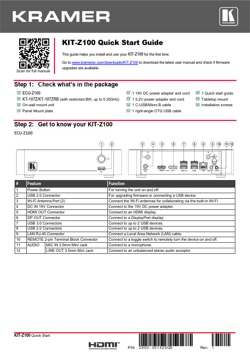
Scan for full manualKIT-Z100 Quick Start GuideThis guide helps you install and use your KIT-Z100 for the first time.Go to /downloads/KIT-Z100 to download the latest user manual and check if firmware upgrades are available.Step 1: Check what’s in the packageECU-Z1001 19V DC power adapter and cord 1 Quick start guide KT-107Z/KT-107ZRB (with restricted BW, up to 5.35GHz) 1 5.2V power adapter and cord Tabletop mount On-wall mount unit 1 C-USB/Micro B cableInstallation screwsPanel Mount plate1 right-angle OTG USB cableStep 2: Get to know your KIT-Z100ECU-Z100KT-107Z/KT-107ZRBBoth Table-top mount and wall mount include the following connectors: • A power connector, when notusing the PoE Ethernet port. • PoE RJ-45 Ethernet Port toconnect to an Ethernet cable. • A USB connector:▪ For the table-top mount, aMicro-USB port, forconnecting an external USB device (for example, a headset or memory disk). ▪ For the wall mount, a Type AUSB port is available using the right-angle OTG USB cable (included).Step 3: Mount ECU-Z100Install ECU-Z100 using one of the following methods:• Attach the rubber feet and place the unit on a flat surface.• Fasten a bracket (included) on each side of the unit and attach it to a flat surface(see /downloads/KIT-Z100).• Mount the unit in a rack using the recommended rack adapter(see /product/KIT-Z100).• Ensure that the environment (e.g., maximum ambient temperature &air flow) is compatible for the device. • Avoid uneven mechanical loading.• Appropriate consideration of equipment nameplate ratings should be used for avoiding overloading of the circuits.• Reliable earthing of rack-mounted equipment should be maintained.Step 4: Mount KT-107Z/KT-107ZRBMounting on a table using one of the following options:Portable Mount: place the tabletop mount on the table. Connected cables remain visible and the table remains intact. Secure Mount: secure the tabletop mount to the table as follows:1. Measure the exact location on the surface of the table where you want to install the KT-107Z/KT-107ZRB.2. Drill a hole in the table and optionally cut the cable pass-through opening according to the cut-out dimensions definedin the user manual.3. Secure the tabletop mount to the table using the M5x60 secure screw.4. Connect the Ethernet port to a PoE-enabled source. Optionally, you can connect the power adapter too (as backup).5. Replace the appropriate cover and place the KT-107Z/KT-107ZRB over the tabletop mount (the is magnetically heldin place), by first inserting the lower part of the then carefully laying the KT-107Z/KT-107ZRB in place.6. Wait for the Home-page to load and then secure the KT-107Z/KT-107ZRB to the tabletop mount from the rear side(using 2 M2x4 screws, supplied with the unit).7. Optionally, lock the tabletop mount with a Kensington locker (not supplied).Mounting on the wall:Before mounting KIT-Z100 on a wall, install an in-wall junction box (recommended boxes are listed in the user manual)1. Attach the on-wall mount unit to the installed junction box (top side up see indication arrows on unit).Connect Ethernet and/or power cables and optionally, insert the right-angle USB cable (supplied) for connecting to an adjacent external USB device.2. Screw the 4 wall-mounting screws (supplied) through the screw openings.The various screw openings fit various types of wall junction boxes.3. On the rear side of the KT-107Z/KT-107ZRB, remove the screwcover and the cover (by slightly pressing downwards and thenpulling out) and set aside.4. Attach the panel mount plate to the rear side of theKT-107Z/KT-107ZRB (using 4 M2x4 screws, supplied).5. Connect the flat cable from the on-wall mount (attached to thein-wall junction box) to the connector on the rear ofKT-107Z/KT-107ZRB.6. Hang the KT-107Z/KT-107ZRB on the wall by sliding the tabs onthe attached panel mount plate over the grooves on the on-wallmount unit.Step 5: Connect inputs and outputsAlways switch OFF the power on each device before connecting it to your KIT-Z100.To achieve specified extension distances, use the recommended Kramer cables available at/product/KIT-Z100. Using third-party cables may cause damage!Microphone and speakers can be connected to ECU-Z100 in the following ways:•Speakers can be connected via LINE OUT connector and/or USB ports.•Microphones cab be connected via MIC IN connector (via amp) and/or USB ports.•Speakerphones (combining a speaker and a microphone) can be connected via USB ports.KT-107Z/KT-107ZRB can be powered in any of the following ways:•Using the power adapter when connected by LAN (without PoE support).•Using the power adapter when connected to LAN by Wi-Fi•By PoE when connecting to Ethernet by PoE-supporting LAN.Step 6: Connect powerConnect the power cord to ECU-Z100 and plug it into the mains electricity.If required, connect the power adapter on the KT-107Z/KT-107ZRB to the Power 2-pin terminal block connector on the tabletop mount and to the mains power.Safety Instructions (See for updated safety information)Caution:•There are no operator serviceable parts inside the unit.Warning:•Use only the power cord that is supplied with the unit.•Disconnect the power and unplug the unit from the wall before installing.•Do not open the unit. High voltages can cause electrical shock! Servicing by qualified personnel only.•To ensure continuous risk protection, replace fuses only according to the rating specified on the product label which located on the bottom of the unit.Step 7: Set and operate KIT-Z100Before setting up the application on KT-107Z/KT-107ZRB, you need to acquire Zoom Rooms licenses.To set and operate the application, go to the Zoom Rooms website at /hc/en-us.To use the Zoom Rooms widget on Kramer Control, go to Zoom Rooms settings at/manuals/kramer/kramer-control/1/en/topic/zoom-room-module.。
S120快速选型

6SL3100-0BE21-6AB0 6SL3100-0BE23-6AB0 6SL3100-0BE25-5AB0 6SL3100-0BE28-0AB0 6SL3100-0BE31-2AB0
6SL3000-0BE21-6DA0 6SL3100-1AE31-0AB0 6SL3100-1BE31-0AA0
z 书本型电机模块
额定 额定 最大 Pn(kW) In(A) Imax(A)
内部风冷
输出电抗器 (选件)
单电机模块
1.6
3
6 6SL3120-1TE13-0AA3 6SE7021-0ES8-0AA3
4.8
9
18 6SL3120-1TE21-0AA3 6SL3000-2BE21-0AA0
附表: 与 20kW 和 40kW 的 BLM 对应的制动电阻
P20
订货号
Rmin(Ω) 连接 20kW BLM
5
6SE7018-0ES87-2DC0
80
是
10
6SE7021-6ES87-2DC0
40
是
20
6SE7023-2ES87-2DC0
20
是
50
6SE7028-0ES87-2DC0
8
否
连接 40kW BLM 是 是 是 是
双轴
Page 2 of 9
I DT MC Gu Hexiang
SINAMICS S120 简易选型 V1.9
2010,07
4. 控制单元和常用选件
名称 控制器及辅助部分
订货号
描述
多轴控制单元 CU320
6SL3040-0MA00-0AA1 Sinamics S120 多轴驱动器的控制单元,带 Profibus-DP 接口
HELP2000G_X_说明书_国内中文_国内标准版_X_R1.00_(X)

HELP2000G稳定控制装置测试装置说明书HELP2000G稳定控制装置测试装置 前言使用产品前,请仔细阅读本章节!本章叙述了使用产品前的安全预防建议。
在安装和使用时, 本章内容必须全部阅读且充分理解。
忽略说明书中相关警示说明,因不当操作造成的任何损害,本公司不承担相应负责。
在对本装置做任何操作前,相关专业人员必须仔细阅读本说明书,熟悉操作相关内容。
l操作指导及警告本手册中将会用到以下指示标记和标准定义:危险! 意味着如果安全预防措施被忽视,则会导致人员死亡,严重的人身伤害,或严重的设备损坏。
警告! 意味着如果安全预防措施被忽视,则可能导致人员死亡,严重的人身伤害,或严重的设备损坏。
警示! 意味着如果安全预防措施被忽视,则可能导致轻微的人身伤害或设备损坏。
本条特别适用于对装置的损坏及可能对被保护设备的损坏。
警告!为增强或修改现有功能,装置的软硬件均可能升级,请确认此版本使用手册和您购买的产品相 兼容。
警告!电气设备在运行时,这些装置的某些部件可能带有高压。
不正确的操作可能导致严重的人身伤 害或设备损坏。
只有具备资质的合格专业工作人员才允许对装置或在装置临近工作。
工作人员需熟知本手册中 所提到的注意事项和工作流程,以及安全规定。
特别注意,一些通用的工作于高压带电设备的工作规则必须遵守。
如果不遵守可能导致严重的 人身伤亡或设备损坏。
危险!在一次系统带电运行时,绝对不允许将与装置连接的电流互感器二次开路。
该回路开路可能会 产生极端危险的高压。
HELP2000G 稳定控制装置测试装置警告!l 曝露端子在装置带电时不要触碰曝露的端子等,因为可能会产生危险的高电压。
l 残余电压在装置电源关闭后,直流回路中仍然可能存在危险的电压。
这些电压需在数秒钟后才会消失。
警示!l 接地装置的接地端子必须可靠接地。
l 运行环境该装置只允许运行在技术参数所规定的大气环境中,而且运行环境不能存在不正常的震动。
l 额定值在接入交流电压电流回路或直流电源回路时,请确认他们符合装置的额定参数。
爱台顿:智能地址可编号火警传感器CAP320、CAPT340、CAH330数据手册说明书

Intelligent addressable sensorsCAP320, CAPT340, CAH330This range of intelligent addressable sensors have been specifically designed to operate with Eaton’s intelligent addressable fire systems.All sensors are third party approved to the relevant section of EN54 (part 7 for smoke detectors, part 5 for heat detectors and part 17 for short circuit isolators).The optical sensor (CAP320) is suitable for mostapplications giving the fastest response to slow burning or smouldering fires which give rise to large visible smoke particles.The photo-thermal sensor (CAPT340) will respond quickly to fast clean burning fires yet maintain the advantage of optical sensors when detecting smouldering fires The thermal enhancement of this sensor allows a higher alarm threshold which provides a greater rejection of false alarms. The sensor will also raise an alarm at temperatures exceeding 60ºC.The CAPT340 has day/night modes available,programmeable from the site installer software. The day mode uses the heat aspect of the sensor for areas which may have smoky environments during, for example working hours. The night mode uses a combination of A2S and smoke detection. If not programmed, the sensor defaults to dual mode.The heat sensor (CAH330) can be set to one of 3 modes 77ºC / 92ºC and rate of rise. These sensors are designed to be used in environments where the ambient conditions might cause false alarms if smoke detection were to be used, for example where there is a high level of dust, fumes, steam or smoke under normal conditions.Features• Soft addressed• Integral short circuit isolator • Single address• Wide range of sensor types• 360° visibility LED using lightpipe technology • Drift compensation •Aesthetically pleasingBenefits• Quick and simple to install • Single “multi-mode” heat sensor• Wide viewing angle for increased LED visibility • Common mounting base • Positive “lock” indication• Discreet design for incorporation into any decor •Easy to maintain/serviceT echnical specificationCode CAP320CAPT340CAH330Description Optical smoke sensorPhoto-Thermal sensorMulti-Mode heat sensorStandards EN54 Pt7 2000 + A1:2002, EN54 Pt17EN54 Pt5 2000 + A1:2002, EN54 Pt7 2000 + A1:2002, EN54 Pt 17EN54 Pt5 2000 + A1:2002, EN54 Pt17Operating volatage 18V dc to 30V dc 18V dc to 30V dc 18V dc to 30V dc Standby current 220μA (max)220μA (max)220μA (max)Alarm current 5mA (max)5mA (max)5mA (max)Addressing mode Auto addressAuto addressAuto addressSpecification Mounting position Ceiling in open areasCeiling in open areasCeiling in open areasMounting options Surface mount with CAB300 base Surface mount with CAB300 base Surface mount with CAB300 base Area coverage 100m² (subject to local standard)100m² (subject to local standard)100m² (subject to local standard)System wiringMin. 1.5mm, 2 core loop or spur Min. 1.5mm, 2 core loop or spur Min. 1.5mm, 2 core loop or spurHeat class Rate of Rise N/A A1S A1R Fixed Heat 77ºC N/A N/A BS Fixed Heat 90ºCN/AN/ACSAlarm Temperature (static)AIR N/A 60ºC 60ºC BS N/A N/A 77ºC CSN/AN/A90ºCIndication360° visibility light pipe360° visibility light pipe360° visibility light pipeEnvironmentalOperating temperature -10°C to +60°C -10°C to +50°C -10°C to +60°C Humidity (non condensing)0 to 95% RH 0 to 95% RH 0 to 95% RHPhysical Construction PC/ABS PC/ABS PC/ABS Colour - Ral No.White - 9003White - 9003White - 9003Dimensions excel base (Dia x D)101mm x 33mm 101mm x 43mm 101mm x 43mm Dimensions incl base (Dia x D)104mm x 45mm 104mm x 55m 104mm x 55mm Weight (without base)76g 76g 76g IP RatingIP30IP30IP30CompatibilitySuitable for use withEaton: Cooper addressable fire systems Eaton: Cooper addressable fire systems Eaton: Cooper addressable fire systemsLED state LED state behaviour System eventOff LED is not illuminated.Global flash is disabled**.Slow flash Momentary flash approximately once every 30 seconds*.Global flash enabled. Detector is in quiescent state.Fast flashMomentary flashapproximately 25 times per minute*.>24 detectors are in fire state.OnLED is constantly illuminated.Detector is in fire state.*Timing can vary depending on loop address quantities.** D etector flash in quiescent state can be disabled via control panel menu (CF3000, CF1100, CF2000).LEDsDescriptionCodeCAP320 Optical smoke sensor 400002FIRE-0002X CAPT340 Photo/Thermal sensor 400004FIRE-0004X CAH330 Multi-Mode heat sensor 400003FIRE-0003X Standard baseCAB300Conventional remote indicatorCIR301Duct probe (requires detector & base)MDP201Loop connected remote indicatorMRIADCatalogue numbersEatonEMEA Headquarters Route de la Longeraie 71110 Morges, Switzerland Eaton.eu© 2019 EatonAll Rights ReservedPublication No. TD-EN-1219December 2019Eaton is a registered trademark.All other trademarks are property of their respective owners.。
MTL Instruments Group plc INM F660A 冗余字段总线电源供应设备说明
INM F660AContents Page CONTENTS PAGE1 Overview . . . . . . . . . . . . . . . . . . . . . . . . . . . . . . . . . . . . . . . . . . . . . . . . . . . . . . . . . . . . . . . . . .12 Description . . . . . . . . . . . . . . . . . . . . . . . . . . . . . . . . . . . . . . . . . . . . . . . . . . . . . . . . . . . . . . . . .13 Components and Accessories . . . . . . . . . . . . . . . . . . . . . . . . . . . . . . . . . . . . . . . . . . . . . . . . . . .14 Mechanical . . . . . . . . . . . . . . . . . . . . . . . . . . . . . . . . . . . . . . . . . . . . . . . . . . . . . . . . . . . . . . . . .25 Installation . . . . . . . . . . . . . . . . . . . . . . . . . . . . . . . . . . . . . . . . . . . . . . . . . . . . . . . . . . . . . . . . .25.1 Location . . . . . . . . . . . . . . . . . . . . . . . . . . . . . . . . . . . . . . . . . . . . . . . . . . . . . . . . . . . . . . . . . . . . . . . . . . . . . . . . . . 25.2 Mounting . . . . . . . . . . . . . . . . . . . . . . . . . . . . . . . . . . . . . . . . . . . . . . . . . . . . . . . . . . . . . . . . . . . . . . . . . . . . . . . . . 25.3 Input power connections . . . . . . . . . . . . . . . . . . . . . . . . . . . . . . . . . . . . . . . . . . . . . . . . . . . . . . . . . . . . . . . . . . . . . . 25.4 Output power connections . . . . . . . . . . . . . . . . . . . . . . . . . . . . . . . . . . . . . . . . . . . . . . . . . . . . . . . . . . . . . . . . . . . . . 25.5 IPM power modules . . . . . . . . . . . . . . . . . . . . . . . . . . . . . . . . . . . . . . . . . . . . . . . . . . . . . . . . . . . . . . . . . . . . . . . . . . 25.6 Alarm module . . . . . . . . . . . . . . . . . . . . . . . . . . . . . . . . . . . . . . . . . . . . . . . . . . . . . . . . . . . . . . . . . . . . . . . . . . . . . . 25.7 Terminators . . . . . . . . . . . . . . . . . . . . . . . . . . . . . . . . . . . . . . . . . . . . . . . . . . . . . . . . . . . . . . . . . . . . . . . . . . . . . . . . 35.8 Testing . . . . . . . . . . . . . . . . . . . . . . . . . . . . . . . . . . . . . . . . . . . . . . . . . . . . . . . . . . . . . . . . . . . . . . . . . . . . . . . . . . . 3. . . . . . . . . . . . . . . . . . . . . . . . . . . . . . . . . . . . . . . . . . . . . . . . . . . . . . . . . . . . . . . .3 6 Maintenance6.1 Routine maintenance . . . . . . . . . . . . . . . . . . . . . . . . . . . . . . . . . . . . . . . . . . . . . . . . . . . . . . . . . . . . . . . . . . . . . . . . . 36.2 Fuse replacement . . . . . . . . . . . . . . . . . . . . . . . . . . . . . . . . . . . . . . . . . . . . . . . . . . . . . . . . . . . . . . . . . . . . . . . . . . . 3© 2007 MTL Instruments Group plc. All rights reserved.1 OV IEWV ER Array The MTL-Relcom redundant fieldbus power system (FPS-Series) provides redundant power conditioning for fieldbus network segments. The system is fully ‘hot-swappable’ meaning that individual power conditioning modules can be removed or replaced without interrupting power or communication on the fieldbus segment.An alarm circuit provides warning in case of a power conditioning module failure or loss of the input power supply. The system is designed so that power for several fieldbus segments can be provided from a single cabinet with minimal wiring.2 DESCRIPTIONThe F660A is designed to provide redundant power for four H1 fieldbus links when used with Honeywell Experion PKS "Series C" Fieldbus Interface Modules (FIMs). It uses the proven MTL-Relcom FPS-IPM power modules, which are mounted on a Honeywell-format I/O Termination Assembly (IOTA) for direct integration into Series C cabinets.The F660A is compatible with Honeywell CC–TFB401 (simplex) and CC–TFB411 (redundant) Fieldbus Interface Module (FIM) IOTAs.The F660A is connected to the FIM IOTA by means of a multi-way cable, available from MTL. The cable carries the conditioned fieldbus power for four fieldbus segments. Different lengths are available to accommodate a variety of mounting locations of the F660A relative to the FIM IOTA. Field wiring connections are made at terminals on the FIM IOTA.Power for the IOTA comes from the redundantly supplied 24V DCbusbars that are embedded in the mounting channel. The connectionto the 0V and 24V busbars is established via mounting screws. Two 24V DC power trains are then created on the IOTA, each protected by a replacable fuse, to provide reliable bulk power to the redundantconditioning modules.4 MECHANICALThe F660A IOTA complies with the mechanical and electrical requirements of 11.6 inch I/O Termination Panels (IOTAs) for direct mounting onto Honeywell Series ‘C’, wide mounting channel. See the dimensional drawing - Figure 2.The IOTA is fixed to the channel with 6 x M3 mounting screws (A), together with the two screws used to connect to the 24V DC and 0V busbars (B and C). Fully assembled the total weight is approximately 1570grams (or 3.46lbs).5 INSTALLATIONIMPORTANTThis equipment may be mounted in a hazardous area, in which case it must be installed, operated and maintained by competent personnel. Such personnel shall have undergone training, which included instruction on the various types of protection and installation practices, the relevant rules and regulations and on the general principles of area classification. It is recommended that appropriate refresher training be given at regular intervals.For all aspects of the F660A specification refer to its datasheet EPS F660A.5.1 LocationThe F660A IOTA may be mounted in a safe area, or a Class I, Division 2, GPs A-D T4 hazardous area. Consult MTL for availability of other approvals.5.2 MountingIt is assumed for the purposes of these installation instructions that the mounting channel is already fitted in a cabinet or enclosure that provides a suitable environment for the FIMs and their associated equipment. Such an environment will be suitable for the F660A IOTA.These mounting instructions may be followed regardless of whether the IOTA has modules fitted or not.It is important to ensure however, that the mounting channel is positioned in a vertical orientation on a vertical surface. This is regarded as the optimum mounting orientation for the F660A-C IOTA and ensures that it will perform to specification within its operating temperature range of –40°C to +65°C. Note that the maximum ambient temperature is limited to 60°C when installed in a Class 1, Division 2 hazardous area.5.2.1 Mounting the carrierMount the IOTA to the channel in the orientation shown in Figure 2. Only when it is in this orientation will it be able to pick up the power bus connections.Position the IOTA, then secure it using the six fixing screws - markedA in Figure 2.5.3 InputpowerconnectionsBusbars located at the rear of the mounting channel provide access to the incoming 24V DC supply.Locate and tighten the screws - marked B (24V) and C (0V) in Figure 2 - to make the connections to the busbars.5.4 OutputpowerconnectionsThe most suitable length of cable to make the connection from the F660A IOTA to the associated FIM can be chosen with reference to the parts list in Section 3 of this manual. Lengths of 30cm (~1ft), 1metre (~3ft 3in), 2metres (~6ft 6in) and 3m (~9ft 9in) are available.With the chosen cable, connect one end to CON5 - marked D on Figure 2. The polarity/orientation is controlled with a keyway to prevent an incorrect connection. The other end of the cable shouldbe routed carefully to the FIM IOTA and the connector inserted there; again with due care for its orientation.5.5 IPMpowermodulesIf not already fitted, the IPM power modules can now be fitted to the IOTA. Locate them one at a time on the circuit board connectors, press firmly onto the IOTA and then tighten the single fixing screw. Repeat this for the rest of the IPM modules.Removal of the power modules is the reverse of fitting, i.e. loosen the fixing screw until the module may be removed from the IOTA.5.6 AlarmmoduleIf not already fitted, the F660A–ALM module fits onto the 16–way multipin connector (CON6) located towards the top of the IOTA and is secured by two captive screws in the module body. To remove the module, first fully release the securing screws and pull the module away from the board.5.6.1 Integratedalarm-signaloperationThe F660A–ALM alarm module monitors the state of each of the eight power conditioning modules and the 24V DC power input. Failures are signalled to the Honeywell Fieldbus Interface Module (FIM) via conductors in the FCAB-0x multi-way cable. In the event of a failed conditioning module, the FIM receives a signal indicating whichon the IOTA, one for each of the segments banks of IPM power modules. The terminators The terminator may be switched in or out for each segment. Push the switch to the ON position (towards the ‘T’ symbol) to enable the 6 MAINTENANCE6.1 RoutinemaintenanceCheck the general condition of the installation occasionally to make sure that no deterioration has occurred. At least every two years (and more frequently for particularly harsh environments) check:◆the condition of wire connection/terminations/screens.◆the dc output voltage on each of the four fieldbussegments is >25V. This can be performed using amultimeter, a Relcom FBT-6 or FBT-3 fieldbus tester.◆that the Power A and Power B LEDs on the F660A-ALMmodule are functioning.◆that the LEDs on all 8 IPM modules are lit.◆that all of the retaining screws are tight.◆that there are no signs of damage or corrosion6.2 FusereplacementTwo fuses, FS1 & FS2, rated at 3.15A each, are incorporated on the IOTA to protect the system from short-circuit fault conditions. One fuse (FSx) supplies the ‘A’ modules and the other (FSy) supplies the ‘B’ modules.Should it be necessary to check or replace the cartridge fuse in either of the fuse holders, insert a flat-bladed screwdriver in the slot on top of the fuse holder and rotate it counter-clockwise as far as the stop (approx. 45°). The fuse cartridge holder will pop out and may then be extracted.If a fuse is found to have blown, it is important to clear the fault before replacing it with a new one.Group Internet home page /Members of The MTL Instruments GroupMTL Instruments Pty Limited 1/30 Canvale Road Canning Vale Perth, WA 6155AustraliaTel: +61 (0)8 9455 2994 Fax: +61 (0)8 9455 2805E-mail:********************.auMTL Canada Safety Instrumentation #102, 4249 97 Street Edmonton, Alberta Canada T6E 5Y7Tel: +1 780 485 3132 Fax: +1 780 485 3122E-mail:***************MTL Instruments Pte Room 1002A, The GatewayNo 10 Yabao Road, Chaoyang District Beijing 100020ChinaTel: +86 010 8562 5718/5720/5721 Fax: +86 010 8562 5725E-mail:*******************MTL Instruments sarl Les Carrés du Parc 10 rue des Rosiéristes69410 Champagne au Mont d’Or FranceTel: +33 (0)4 78 64 98 32 Fax: +33 (0)4 78 35 79 41E-mail:****************MTL Instruments GmbH An der Gümpgesbrücke 17D-41564 Kaarst GermanyTel: +49 (0)2131 718930 Fax: +49 (0)2131 7189333E-mail:***********MTL India Pvt. Limited No. 36, Nehru StreetOff Old Mahabalipuram Road SholinganallurChennai - 600 119IndiaTel: + 91 (0)44 24501660/24501857 Fax: + 91 (0)44 24501463E-mail:******************MTL Italia srl Via Cantù 11I - 20092 Cinisello Balsamo MI ItalyTel: +39 (0)2 61802011 Fax: +39 (0)2 61294560E-mail:****************MTL Instruments KK3rd Floor, Gotanda Masujima Building 1-8-13 Higashi-Gotanda, Shinagawa-Ku Tokyo 141-0022JapanTel: +81 (0)3 5420 1281 Fax: +81 (0)3 5420 2405E-mail:**************.jpMTL Instruments BVPO Box 55, 6680 AB Bemmelde Houtakker 36, 6681 CW Bemmel The NetherlandsTel: +31 (0)481 450250 Fax: +31 (0)481 450260E-mail:*******************MTL Instruments Pte Limited 31 Ubi Road 1#04-01 Aztech Building Singapore 408694Tel: +65 6 487 7887 Fax: +65 6 487 7997E-mail:*****************.sgMTL InstrumentsVilla No. 4, Sector 2-17,Street 6PO Box 53234, Abu Dhabi, UAETel: +971 2 446 6840 Fax: +971 2 446 6841E-mail:********************Measurement Technology Limited Power Court, Luton, Bedfordshire England LU1 3JJTel: +44 (0)1582 723633 Fax: +44 (0)1582 422283E-mail:********************MTL Incorporated4001 W. Sam Houston Parkway N. Suite 150, Houston TX 77043USATel: +1 281 571 8065 Fax: +1 281 571 8069E-mail:*****************。
DS-K2600系列门禁控制器快速启动指南说明书
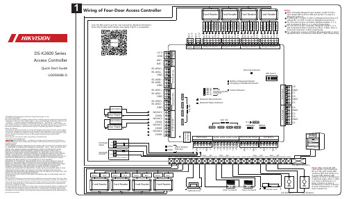
DS-K2600 SeriesAccess ControllerQuick Start GuideUD05848B-DCOPYRIGHT ©2019 Hangzhou Hikvision Digital Technology Co., Ltd.ALL RIGHTS RESERVED.Any and all information, including, among others, wordings, pictures, graphs are the properties of Hangzhou Hikvision Digital Technology Co., Ltd. or its subsidiaries (hereinafter referred to be “Hikvision”). This user manual (hereinafter referred to be “the Manual”) cannot be reproduced, changed, translated, or distributed, partially or wholly, by any means, without the prior written permission of Hikvision. Unless otherwise stipulated, Hikvision does not make any warranties, guarantees or representations, express or implied, regarding to the Manual.About this ManualThe Manual includes instructions for using and managing the product. Pictures, charts, images and all other information hereinafter are for description and explanation only. The information contained in the Manual is subject to change, without notice, due to firmware updates or other reasons. Please find the latest version in the company website (http://overseas.hikvi-/en/).Please use this user manual under the guidance of professionals.Trademarks Acknowledgementand other Hikvision’s trademarks and logos are the properties of Hikvision in various jurisdictions. Other trademarks and logos mentioned below are the properties of their respective owners.Legal DisclaimerTO THE MAXIMUM EXTENT PERMITTED BY APPLICABLE LAW, THE PRODUCT DESCRIBED, WITH ITS HARDWARE, SOFTWARE AND FIRMWARE, IS PROVIDED “AS IS”, WITH ALL FAULTS AND ERRORS, AND HIKVISION MAKES NO WARRANTIES, EXPRESS OR IMPLIED, INCLUDING WITHOUT LIMITATION, MERCHANTABILITY, SATISFACTORY QUALITY, FITNESS FOR A PARTICULAR PURPOSE, AND NON-INFRINGEMENT OF THIRD PARTY. IN NO EVENT WILL HIKVISION, ITS DIRECTORS, OFFICERS, EMPLOYEES, OR AGENTS BE LIABLE TO YOU FOR ANY SPECIAL, CONSEQUENTIAL, INCIDENTAL, OR INDIRECT DAMAGES, INCLUDING, AMONG OTHERS, DAMAGES FOR LOSS OF BUSINESS PROFITS, BUSINESS INTERRUPTION, OR LOSS OF DATA OR DOCUMENTATION, IN CONNECTION WITH THE USE OF THIS PRODUCT, EVEN IF HIKVISION HAS BEEN ADVISED OF THE POSSIBILITY OF SUCH DAMAGES.REGARDING TO THE PRODUCT WITH INTERNET ACCESS, THE USE OF PRODUCT SHALL BE WHOLLY AT YOUR OWN RISKS. HIKVISION SHALL NOT TAKE ANY RESPONSIBILITES FOR ABNORMAL OPERATION, PRIVACY LEAKAGE OR OTHER DAMAGES RESULTING FROM CYBER ATTACK, HACKER ATTACK, VIRUS INSPECTION, OR OTHER INTERNET SECURITY RISKS; HOWEVER, HIKVISION WILL PROVIDE TIMELY TECHNICAL SUPPORT IF REQUIRED. SURVEILLANCE LAWS VARY BY JURISDICTION. PLEASE CHECK ALL RELEVANT LAWS IN YOUR JURISDICTION BEFORE USING THIS PRODUCT IN ORDER TO ENSURE THAT YOUR USE CONFORMS THE APPLICABLE LAW. HIKVISION SHALL NOT BE LIABLE IN THE EVENT THAT THIS PRODUCT IS USED WITH ILLEGITIMATE PURPOSES.IN THE EVENT OF ANY CONFLICTS BETWEEN THIS MANUAL AND THE APPLICABLE LAW, THE LATER PREVAILS.Data ProtectionDuring the use of device, personal data will be collected, stored and processed. To protect data, the development of Hikvision devices incorporates privacy by design principles. For example, for device with facial recognition features, biometrics data is stored in your device with encryption method; for fingerprint device, only fingerprint template will be saved, which is impossible to reconstruct a fingerprint image.As data controller, you are advised to collect, store, process and transfer data in accordance with the applicable data protection laws and regulations, including without limitation, conducting security controls to safeguard personal data, such as, implementing reasonable administrative and physical security controls, conduct periodic reviews and assessments of the effectiveness of your security controls.Scan the QR code to get the user manual for detailed information. Note that mobile data charges may apply if Wi-Fi is unavailable.Set Bit 6 of the card reader DIP switch to OFF and set Bit1 to 4 as the DIP address.Note: DIP address of Door 1 (Entrance) is 1 (decimalvalue), Door 1 (Exit) is 2, Door 2 (Entrance) is 3, Door 2(Exit) is 4, Door 3 (Entrance) is 5, Door 3 (Exit) is 6, Door 4(Entrance) is 7, and Door 4 (Exit) is 8.DIP Switch DescriptionTake the 8-bit DIP switch as an example; No.1 to No 8 is from the low bit to the high bit.When the switch is towards ON, it means the switch is enabled, otherwise, the switch is off.If you set the DIP switch like the figure displayed below, its binary value is 00001100, and itsdecimal value is 12.DIP Switch Settings of RS-485 Card ReaderDIP Switch Settings of Wiegand Card ReaderSet Bit 6 of the card reader DIP switch to ON and set Bit 7 toselect a Wiegand protocol.Note: If setting Bit 7 as ON, it refers to Wiegand 26protocol. If setting Bit 7 as OFF, it refers to Wiegand 34protocol.DIP Switch of Door 1 (Entrance)DIP Switch of Wiegand 26 ProtocolRegulatory InformationFCC InformationPlease take attention that changes or modification not expressly approved by the party responsible forcompliance could void the user’s authority to operate the equipment.FCC compliance: This equipment has been tested and found to comply with the limits for a Class Bdigital device, pursuant to part 15 of the FCC Rules. These limits are designed to provide reasonableprotection against harmful interference in a residential installation. This equipment generates, usesand can radiate radio frequency energy and, if not installed and used in accordance with theinstructions, may cause harmful interference to radio communications. However, there is no guaranteethat interference will not occur in a particular installation. If this equipment does cause harmfulinterference to radio or television reception, which can be determined by turning the equipment offand on, the user is encouraged to try to correct the interference by one or more of the followingmeasures:—Reorient or relocate the receiving antenna.—Increase the separation between the equipment and receiver.—Connect the equipment into an outlet on a circuit different from that to which the receiver isconnected.—Consult the dealer or an experienced radio/TV technician for help.FCC ConditionsThis device complies with part 15 of the FCC Rules. Operation is subject to the following twoconditions:1. This device may not cause harmful interference.2. This device must accept any interference received, including interference that may cause undesiredoperation.EU Conformity StatementThis product and - if applicable - the supplied accessories too are marked with "CE" andcomply therefore with the applicable harmonized European standards listed under theR&TTE Directive 1999/5/EC, the EMC Directive 2014/30/EU, the LVD Directive2014/35/EU, the RoHS Directive 2011/65/EU.2012/19/EU (WEEE directive): Products marked with this symbol cannot be disposed ofas unsorted municipal waste in the European Union. For proper recycling, return thisproduct to your local supplier upon the purchase of equivalent new equipment, ordispose of it at designated collection points. For more information see: www.recycle-.2006/66/EC (battery directive): This product contains a battery that cannot be disposedof as unsorted municipal waste in the European Union. See the product documentationfor specific battery information. The battery is marked with this symbol, which mayinclude lettering to indicate cadmium (Cd), lead (Pb), or mercury (Hg). For properrecycling, return the battery to your supplier or to a designated collection point. Formore information see: .Industry Canada ICES-003 ComplianceThis device meets the CAN ICES-3 (B)/NMB-3(B) standards requirements.6DIP Switch Settings of Card Reader。
HSAD火灾监控
消防端子:采用 ZR-BVR 线,截面积不小于
电源端子:采用 ZR-BV 线,截面积不小于 1.5mm2 。
4
5
2. HSAD-S 系列电气火灾监控设备
丰富的网络接口资源 设备预留有速率 1000Mbit/s 以太网接口,在实际的应用中很方便根据工作现场接入网设备和接入方式接入城市智能消防或智 能电网系统。设备预留的 RS485 接口,及 CAN 总线接口也可以与其他厂商的监控探测器或低压电器连接。 先进可靠高效的网络架构 设备采用了无主从网络构架的 CAN 总线方案,可以直接连接我公司的监控探测器,满足实时报警及数据监测的要求,最后一 层为 RS485 接口及开关量输入输出接口,满足其他设备的网络连接要求。 满足新修订标准的技术要求: 根据国家公安消防部门对 GB14287-20XX 在 2010 年的修订结果我们的产品功能做必要的设计改进,满足新标准的技术要求。 智能化图形监控界面: 本系统采用 windows 系统友好界面设计,方便各类技术人群管理监控,系统监控过程一目了然,并实时显示漏电报警和故障 位置,很方便现场设备管理人员的监控和管理。 先进的网络管理服务功能: 可通过接入网技术实现远程访问设备,完成数据监测,系统维护升级等操作。 同一局域网内可实现多台监控设备进行联网,实现数据共享,不同设备故障监管等功能。
2.1.1 主要技术指标
项目类别 产品型号 产品货号 设备容量(地址数) HSAD-S1 HS-S001 ~ 3 32、64、128 个地址 单色 240×128 液晶显示屏,全中文显示 CAN 总线,有效通讯距离 3000 米 ZR-RVVP,截面积 1.0 ~ 1.5 mm2 AC220V;50Hz;20W DC12V:1 节 12V 4Ah 密封免维护铅酸电池 1条 差分电压最高值≤ 3V HSAD-R、HSAD-R1、HSAD-R4、HSAD-RT 系列 壁挂式 350mm×480mm×120mm(宽 * 高 * 厚) 温度 -10℃~ 40℃,相对湿度≤ 90%RH 9kg( 含电池 ) 屏蔽双绞双色线(红黑两色) 参 数
海康威视 DP1511、DP1521 和 DP1531 非接触红外热度监测系统产品说明书

The DP1511, DP1521 and DP1531 non-contact infrared thermal monitoring systems represent a unique technological approach for monitoring and controlling process temperatures. These units combine fiber optics or line-of-sight optics with advanced electronic technology into a system that continuously monitors infrared radiation (a function of temperature) in real time and without physically contacting the target material. The result is a highly reliable system offering outstanding accuracy and repeatability with high response speed.
The DP1531 high speed monitor is used with either the OS1532 infrared or OS1533 fiber optic sensors.
J-122
Specifications
Temperature Range: DP1511, DP1521: 50 to 3700°C (120 to 6692°F) DP1531: 75 to 2300°C (165 to 4172°F)
Temperature Indicators
杭州日升电气设备 制袋机微电脑控制器 说明书

制袋机微电脑控制器用户手册杭州日升电气设备有限公司地址:杭州市富强路48号电话:0571-******** 881860751.总介2.使用说明3.注意事项4.常见问题解答5.附录一:功能码和错误码说明6.附录二:接线端子说明本文档内容为杭州日升电气设备有限公司制袋机微电脑控制器之使用说明与注意事项。
操作者应在详细阅读本手册后方可进行操作,在使用中如遇任何问题,可先参考注意事项和常见问题解答。
§使用说明图一控制器面板图一为控制器面板图,主要由三大功能块组成:键盘,显示,和商标。
所有设置和控制都可通过键盘方便、快速地实现。
1.键盘说明键盘由14个按钮组成,功能说明如下:¾设置:‘设置’按钮用来进入设置状态。
设置以功能码的形式进行,按压‘设置’按钮一次进入功能码01,功能为修改制袋长度,拉料速度,和其他几个功能码设置不同的是,此时并不显示¾←:‘←’按钮在进入设置状态后,用来左移闪烁位。
¾→:‘→’按钮在进入设置状态后,用来右移闪烁位。
¾↑:‘↑’按钮在进入设置状态后,使闪烁位数值加1,最低位带进位。
¾↓:‘↓’按钮在进入设置状态后,使闪烁位数值减1,最低位带借位。
¾总清:‘总清’按钮将制袋累计数清为零。
¾清零:‘清零’按钮将当前批次制袋数清为零。
¾正转:‘正转’按钮按下后将由慢到快向前拉料。
¾反转:‘反转’按钮按下后将由慢到快向后拉料。
¾快/慢:‘快/慢’按钮选择做印刷袋时为快检测或慢检测,做空白袋时不起作用。
按钮中的灯亮时为快检测,暗时为慢检测,慢检测主要用来调整制袋长度,以获得合适的检测距离,快检测为正常制袋时使用。
两种状态可在运行中动态切换。
¾印/空:‘印/空’按钮选择做印刷袋或空白袋。
按钮中的灯亮时为印刷袋,暗时为空白袋。
两种状态可在运行中动态切换。
¾黑/白:‘黑/白’按钮选择做印刷袋时检测色标为黑有效或白有效。
CDSK-3100变电站智能锁控系统技术说明书

CDSK-3100(3200)变电站智能锁控系统技术说明书江苏崇道电力科技有限公司2012-9-16目录一、概述概述适用范围二、系统工作原理基本原理五防操作流程预演操作实际操作通道门操作流程正常权限操作临时授权操作三、型号分类纯五防型变电站智能锁控系统CDSK-3120纯通道门型变电站智能锁控系统CDSK-3130带图形模拟型变电站智能锁控系统CDSK-3140不带图形模拟型变电站智能锁控系统四、闭锁实现方法断路器闭锁实现方式遥控操作的闭锁就地操作闭锁电动刀闸闭锁实现方法刀闸机构箱端子箱遥控操作线路验电闭锁实现方式有源正验电有源负验电无源负验电五、主要部件介绍智能钥匙多功能适配器简易适配器锁具及附件六、性能指标使用环境环境温度环境湿度电磁干扰强度额定参数主机模拟屏智能钥匙智能适配器电编码锁编码挂锁接地锁解锁钥匙七、常见故障处理附录一存贮及保修附录二开箱及检查附录三供货的成套性附录四订货须知附录五五防常识特别提示:本书说明是CDSK-3100单站式变电站智能锁控系统、CDSK-3200集控型变电站智能锁控系统共同的说明书,但书中描述以CDSK-3100单站式变电站智能锁控系统为例。
一、概述概述在发电厂和变电站等环境中存在大量的锁具,大致分为两类:1、五防锁:对一次电气设备进行闭锁、具有五防闭锁功能;2、通道门锁:对重要区域出入通道门、各类设备箱柜门及各类手动设备操作机构进行闭锁。
对第一类锁具,目前常见的是采用微机防误操作闭锁系统对其进行统一操作和管理。
而对通道门锁,多是采用一把钥匙开一把锁的原始模式操作。
市场上还没有对五防锁和通道门锁进行统一操作和管理的产品。
CDSK-3100(3200)变电站智能锁控系统是目前唯一将两类锁具集成在一个平台上进行统一管理的系统,率先填补了这一领域的空白,具备如下特点:1、锁具管理全覆盖,即具备五防闭锁功能,又可对通道门锁进行管理。
2、对通道门锁采用权限管理模式,用户登陆钥匙后可在权限范围内自由操作,并可对操作过程进行记录;用户无操作权限则不能操作。
- 1、下载文档前请自行甄别文档内容的完整性,平台不提供额外的编辑、内容补充、找答案等附加服务。
- 2、"仅部分预览"的文档,不可在线预览部分如存在完整性等问题,可反馈申请退款(可完整预览的文档不适用该条件!)。
- 3、如文档侵犯您的权益,请联系客服反馈,我们会尽快为您处理(人工客服工作时间:9:00-18:30)。
本产品上使用的标记 本产品上可能出现如下标记:
警告高压
保护性终端
小心
测量接地端
电源开关
IV SPD3303X 面板功能介绍
SIGLENT
SPD3303X 简介
SPD3303X 直流电源,轻便,可调,多功能工作配置。它具有三组独立输出:两 组可调电压值和一组固定可选择电压值 2.5V、3.3V、和 5V,同时具有输出短路和过 载保护。
SPD3303X 可编程线性直流电源
面板功能介绍
2016 深圳市鼎阳科技有限公司
版权和声明
SIGLENT
版权
深圳市鼎阳科技有限公司版权所有
商标信息
SIGLENT 是深圳市鼎阳科技有限公司的注册商标
声明
本公司产品受已获准及尚在审批的中华人民共和国专利的保护。 本公司保留改变规格及价格的权利。 本手册提供的信息取代以往出版的所有资料。 未经本公司许可,不得以任何形式或手段复制、摘抄、翻译本手册的内容。
VI SPD3303X 面板功能介绍
SIGLENT
3.3 命令说明................................................................................................................... 29 第四章 常见故障处理...........................................................................................................36 第五章 服务和支持...............................................................................................................37
保险丝 保险丝型号:100V/120V:T6.3A/250V;220V/230V:T3.15A/250V 开机前确保使用正确的保险丝型号; 保险丝替换前不要连接电源线; 替 换保险丝前确定保险丝烧断原因。
将产品接地 本产品通过电源的接地导线接地。为避免电击,接地导体必须与地相连。在连接 本产品的输入与输出之前,请务必将本产品接地。
一般性检查........................................................................................................................ 2 注意事项............................................................................................................................ 3 前面板................................................................................................................................ 4 用户界面............................................................................................................................ 7 后面板................................................................................................................................ 8 输出检查............................................................................................................................ 9 第二章 控制面板操作...........................................................................................................10 2.1 输出综述....................................................................................................................11 2.2 CH1/CH2 独立输出 .................................................................................................. 12 2.3 CH3 独立模式 ........................................................................................................... 13 2.4 CH1/CH2 串联模式 ................................................................................................. 14 2.5 CH1/CH2 并联模式 .................................................................................................. 15 2.6 网络设置................................................................................................................... 16 2.7 保存和调出............................................................................................................... 17 2.8 定时器....................................................................................................................... 18 2.9 波形显示................................................................................................................... 21 2.10 版本信息和锁键..................................................................................................... 22 2.11 版本升级................................................................................................................. 23 第三章 远程控制...................................................................................................................26 3.1 语法惯例.................................................................................................................... 27 3.2 命令概要.................................................................................................................... 28
主要特点: 采用 4.3 寸 16M 真彩 TFT 液晶屏; 独立三通道其中两通道可控输出,总输出功率达 195W; 100V/120V/220V/230V 兼容设计,满足不同电网需求; 具有存储和调用设置参数功能; 具有定时输出功能; 具有波形显示功能,实时显示电压/电流波形,配合数字显示的电压、电流和 功率数值;
查看所有终端额定值 为避免起火或过大电流的冲击,请查看产品上所有的额定值和标记说明,在连接 产品前查阅产品手册以了解额定值的详细信息。
保持适当的通风 通风不良会引起仪器温度升高,进而引起仪器损坏,使用时请保持良好的通风, 并定期检查通风口和风扇。
II SPD3303X 面板功能介绍
SIGLENT
操作环境 位置:户内、无强光、无尘、几乎无干扰性污染; 相对湿度:<80% 海拔:<2000m 温度:0℃到 40℃
定时(30 分钟)启动屏幕保护程序 完善的 PC 平台控制软件,可通过 USBTMC、LAN 实现实时控制
SPD3303X 面板功能介绍
V
SIGLENT
目录 版权和声明 ................................................................................................................................I 一般安全概要.......................................................................................................................... II 安全术语和标记 ..................................................................................................................... IV SPD3303X 简介 ..................................................................................................................... V 第一章 入门指南.....................................................................................................................1
