数字设计课件第七章时序逻辑设计原理
《数字系统设计》PPT课件

慎重地加以选择。总的原则是,所选择的方案既要能满足系统的
要求,又要结构简单,实现方便,具有较高的性能价格比。
a
7
第7章 数字系统设计
2. 逻辑划分,导出系统框图
系统总体方案确定以后,可以根据数据子系统和控制子系统 各自的功能特点,将系统从逻辑上划分为数据子系统和控制子系 统两部分,导出包含有必要的数据信息、 控制信息和状态信息的 结构框图。逻辑划分的原则是, 怎样更有利于实现系统的工作原 理,就怎样进行逻辑划分。 为了不使这一步的工作太过复杂,结 构框图中的各个逻辑模块可以比较笼统、比较抽象,不必受具体 芯片型号的约束。
a
5
第7章 数字系统设计 7.1.2 数字系统设计的一般过程
系统调研 ,确定总体 方案
逻辑划分 ,导出系统 框图
功能分解 ,构造数据 子系统
算法设计 ,实现控制 子系统
图 7 - 2 数字系统设计过程
a
6
第7章 数字系统设计 1. 系统调研, 确定总体方案
接受一个数字系统的设计任务后,首先应对设计课题进行充
第7章 数字系统设计
第7章 数字系统设计
7.1 数字系统设计概述 7.2 控制子系统的设计工具 7.3 控制子系统的实现方法 7.4 数字系统设计举例
a
1
第7章 数字系统设计
7.1 数字系统设计概述
1. 什么是数字系统
在数字电子技术领域内,由各种逻辑器件构成的能够实现某
种单一特定功能的电路称为功能部件级电路,例如前面各章介绍
分的调研, 深入了解待设计系统的功能、使用环境与使用要求,
选取合适的工作原理与实现方法,确定系统设计的总体方案。 这
是整个设计工作中最为困难也最体现设计者创意的一个环节。因
数字电子技术基础 时序逻辑电路 时序逻辑电路的设计方法PPT学习教案
J3 Q2Q1Q0
J
2
Q1Q0
J1 Q0
J
0
Q3Q2
K3 Q2 K2 Q3Q1Q0 K1 Q0 K0 1
第6页/共34页
由驱动方程可画出十三进制计数器的逻辑电路,如图5.4.2所 示
CP
FF0
FF1
FF2
Q2 FF3
1J Q C1
Q0 1J
Q1 Q
C1
& 1J Q C1
10/00 01/00
AB/XY S2
00/00
注:由于实际中不可能同时投入一枚一元硬币和五角硬币,故 AB=11的情况不出现,做约束项处理。
第13页/共34页
设S0、S1和S2分别用00、01和10表示,则取触发器的位数为M=3
则电路的次态/输出的卡诺 图为
AB
Q1n Q0n
00
00
00/00
01 11 10
1
S2 0 0 1 0 0
2
S3 0 0 1 1 0
3
S4 0 1 0 0 0
4
S5 0 1 0 1 0
5
S6 0 1 1 0 0
6
S7 0 1 1 1 0
7
S8 1 0 0 0 0
8
S9 1 0 0 1 0
9
S10 1 0 1 0 0
10
S11 1 0 1 1 0
11
S12 1 1 0 0 1
12
11 × × × × 10 0 0 × 0
Q0n1
11 × × × × 10 0 1 × 1
Y
11 × × × × 10 0 0 × 1
Z
第14页/共34页
《时序逻辑电路分析》课件

采用低功耗、高速的触发器设计,减少资源占用。
提高工作速度的优化方法
并行处理
通过并行处理技术,提高电路的工作 速度。
时钟分频与倍频
根据电路的工作频率需求,合理选择 时钟的分频与倍频方案,以优化工作 速度。
THANKS
感谢观看
REPORTING
PART 03
时序逻辑电路的设计
REPORTING
同步设计法
01
同步设计法定义
同步设计法是一种基于时钟信号 的设计方法,用于构建时序逻辑
电路。
03
优点
同步设计法具有较高的可靠性和 稳定性,能够实现复杂的逻辑功
能。
02
工作原理
在同步设计法中,所有操作都严 格在时钟信号的驱动下进行,保 证了电路的稳定性和可靠性。
《时序逻辑电路分析 》PPT课件
REPORTING
• 时序逻辑电路概述 • 时序逻辑电路的分析方法 • 时序逻辑电路的设计 • 时序逻辑电路的应用 • 时序逻辑电路的优化设计
目录
PART 01
时序逻辑电
时序逻辑电路的定义、特点
时序逻辑电路的特点包括
具有记忆功能、具有时钟信号控制、具有输入信号和输出信号等。
时序逻辑电路的基本组成
时序逻辑电路由触发器、组合逻 辑电路和时钟信号源三部分组成 。
组合逻辑电路用于实现输入信号 到输出信号的逻辑变换,主要由 门电路组成。
总结词:时序逻辑电路的基本组 成
触发器是时序逻辑电路中的核心 元件,用于存储状态信息,常见 的触发器有RS触发器、D触发器 、JK触发器和T触发器等。
04
异步时序逻辑电路是指触发器的时钟输入端接在不同的时钟源上,时 钟信号独立作用于各个触发器,实现状态异步转换。
数字电路系统设计中英文课件教程 07 时序逻辑电路原理-Sequential Logic Design Principles (1)

metastable 亚稳态
stable
稳态
stable
稳态
7.2 Latches and Flip-Flops (锁存器与触发器)
—— The Basic Building Blocks of most Sequential Circuits. (大多数时序电路的基本构件)
Clock Frequency: The Reciprocal of the Clock Period
(时钟频率:时钟周期的倒数。)
Clock Tick: The First Edge of Pulse in a clock period or sometimes the period itself.
DIGITAL SYSTEM DESIGN
ESHINE
eshine.li@
Chapter 7 Sequential Logic Design Principles ( 时序逻辑设计原理 )
Latches and Flip-Flops (锁存器和触发器 ) Clocked Synchronous State-Machine Analysis (同步时序分析) Clocked Synchronous State-Machine Design (同步时序设计)
Basic Concepts (基本概念)
Sequential Logic Circuit (时序逻辑电路) Clock Period: The Time between Successive transitions in the same direction.
(时钟周期:两次连续同向转换之间的时间。)
Latches(锁存器)
数字设计课件 第七章 时序逻辑设计原理
4
Chapter 7
7.1 Bistable Element
1
feedback
2
Q is the state variable
• Output variable:Q,Q_L,且Q_L=Q’ • Two stable state:
Q=0、Q_L=1 Q=1、Q_L=0
5 Chapter 7
analysis with transfer characteristic
2
Chapter 7
Some important concepts
• state and state variable
state : collection of state variable, contain all the information about the past necessary to account for the circuit’s future behavior. state variable: the symbol representation of state. n state 2n possible
•
25
of master latch. It is not edge-triggered f-fs, but pulsetriggered.
Chapter 7
Timing diagram of S-R f-fs
C
S
R QM QM_L Q Q_L
26
Chapter 7
9. master/slave J-K flip-flop
21 Chapter 7
frequency divider with D f-fs
D
Q
(frequency, fout) output
时序逻辑电路PPT课件

工作原理
状态表示
时序逻辑电路中的状态通常由存储元件(如触发器)来存储,根据 输入信号的变化,电路的状态会随之改变。
状态转移
时序逻辑电路中的状态转移是由输入信号和当前状态共同决定的, 根据一定的逻辑关系,电路会从一个状态转移到另一个状态。
。
02
可编程逻辑控制器(PLC)
在工业控制系统中,时序逻辑电路用于实现可编程逻辑控制器,用于自
动化控制和数据处理。
03
传感器接口
时序逻辑电路用于实现传感器接口电路,将传感器的模拟信号转换为数
字信号,并传输给微控制器或可编程逻辑控制器进行处理。
04
CATALOGUE
时序逻辑电路的优化
优化设计
设计
使用基本的逻辑门电路, 根据需求逐一设计电路。
自动化工具设计
使用EDA(电子设计自动 化)工具进行设计,提高 设计效率。
混合设计
结合手工设计和自动化工 具设计,根据具体情况选 择合适的设计方法。
设计工具
硬件描述语言
使用Verilog或VHDL等硬件描述语言进行设计。
EDA工具
时序逻辑电路
目录
• 时序逻辑电路简介 • 时序逻辑电路设计 • 时序逻辑电路的应用 • 时序逻辑电路的优化 • 时序逻辑电路的发展趋势
01
CATALOGUE
时序逻辑电路简介
定义与分类
定义
时序逻辑电路是一种具有记忆功 能的电路,它能够根据输入信号 的变化,按照一定的逻辑关系, 输出相应的信号。
分类
输出信号
时序逻辑电路的输出信号是根据当前状态和输入信号来确定的,它会 随着状态的变化而变化。
电子线路基础数字电路实验7 时序逻辑电路设计

实验七时序逻辑电路设计一、实验目的1. 学习用集成触发器构成计数器的方法。
2. 熟悉中规模集成十进制计数器的逻辑功能及使用方法。
3. 学习计数器的功能扩展。
4. 了解集成译码器及显示器的应用。
二、实验原理计数器是一种重要的时序逻辑电路,它不仅可以计数,而且用作定时控制及进行数字运算等。
按计数功能计数器可分加法、减法和可逆计数器,根据计数体制可分为二进制和任意进制计数器,而任意进制计数器中常用的是十进制计数器。
根据计数脉冲引入的方式又有同步和异步计数器之分。
1. 用D触发器构成异步二进制加法计数器和减法计数器:图10—1是用四只D触发器构成的四位二进制异步加法计数器,它的连接特点是将每只D触发器接成T'触发器形式,再由低位触发器的Q端和高一位的CP端相连接,即构成异步计数方式。
若把图10—1稍加改动,即将低位触发器的Q端和高一位的CP端相连接,即构成了减法计数器。
图10—1本实验采用的D触发器型号为74LS74A,引脚排列见前述实验。
2. 中规模十进制计数器中规模集成计数器品种多,功能完善,通常具有予置、保持、计数等多种功能。
74LS182同步十进制可逆计数器具有双时钟输入,可以执行十进制加法和减法计数,并具有清除、置数等功能。
引脚排列如图10—2所示。
其中LD−−置数端;CP u−−加计数端;CP D−−减计数端;DO−−非同步进位输出端;CO−−非同步借位输出端;Q A、Q B、Q C、Q D−−计数器输出端;D A、D B、D C、D D−−数据输入端;CR−−清除端。
表10—1为74LS192功能表,说明如下:当清除端为高电平“1”时,计数器直接清零(称为异步清零),执行其它功能时,CR置低电平。
当CR为低电平,置数端LD为低电平时,数据直接从置数端D A、D B、D C、D D置入计数器。
当CR为低电平,LD为高电平时,执行计数功能。
执行加计数时,减计数端CP D接高电平,计数脉冲由加计数端Cp u输入,在计数脉冲上升沿进行842编码的十进制加法计数。
数字电路 第七章 时序逻辑电路
/0 001
/0
010 /0
101
100 /1 /0
011
结论:该电路是一个同步五进制( ⑥ 结论:该电路是一个同步五进制(模5)的加 法计数器,能够自动启动, 为进位端. 法计数器,能够自动启动,C为进位端.
§7.3 计数器
7.3.1 计数器的功能和分类
1. 计数器的作用
记忆输入脉冲的个数;用于定时,分频, 记忆输入脉冲的个数;用于定时,分频,产 生节拍脉冲及进行数字运算等等. 生节拍脉冲及进行数字运算等等.
1 0 1 0 1 0 1 0
3. 还可以用波形图显示状态转换表. 还可以用波形图显示状态转换表.
CP Q0 Q1 Q2
思考题: 思考题:试设计一个四位二进制同步加法计数 器电路,并检验其正确性. 器电路,并检验其正确性.
7.3.4 任意进制计数器的分析
例:
Q2 J2 Q2 K2 Q1 J1 Q1 K1 Q0 J0 Q0 K0
第七章 时序逻辑电路
§7.1 概述 §7.2 时序逻辑电路的分析方法 §7.3 计数器 §7.4 寄存器和移位寄存器 §7.5 计数器的应用举例
§7.1Байду номын сангаас概述
在数字电路中, 在数字电路中,凡是任一时刻的稳定 输出不仅决定于该时刻的输入,而且还和 输出不仅决定于该时刻的输入,而且还和 电路原来的状态有关者 电路原来的状态有关者,都叫做时序逻辑 电路,简称时序电路 时序电路. 电路,简称时序电路. 时序电路的特点:具有记忆功能. 时序电路的特点:具有记忆功能.
下面将重点 讨论蓝颜色 电路—移位 电路 移位 寄存器的工 寄存器的工 作原理. 作原理. D0 = 0 D1 = Q0 D2 = Q1 D3 = Q2
电子设计中的时序逻辑设计
电子设计中的时序逻辑设计时序逻辑设计是电子设计中非常重要的一个部分,它主要涉及到在数字电路中对信号的时序进行控制和调整,以确保电路能够按照预定的顺序正确地工作。
在电子设备中,时序逻辑设计直接影响着整个系统的性能、稳定性和功耗等方面。
首先,时序逻辑设计需要考虑时钟信号的控制。
时钟信号是数字系统中非常关键的一个信号,它提供了同步的时序参考,确保各个部分能够同时工作。
在时序逻辑设计中,需要合理地设置时钟信号的频率、相位和占空比等参数,以保证整个系统的稳定性和可靠性。
其次,时序逻辑设计还涉及到时钟域的概念。
数字系统中的不同部分可能工作在不同的时钟频率下,这就涉及到时钟域之间的数据传输和同步。
在时序逻辑设计中,需要考虑时钟域之间的同步问题,采取合适的方法来确保数据的正确传输和处理。
此外,时序逻辑设计还需要考虑信号的延迟和时序约束。
在数字系统中,信号的传输会存在一定的延迟,这可能会导致时序不一致的问题。
因此,在时序逻辑设计中,需要对信号的延迟进行分析和优化,以满足系统的时序约束要求,确保数据的正确性和稳定性。
在实际的时序逻辑设计中,通常会采用时序分析工具来辅助设计。
时序分析工具可以帮助设计工程师对时序逻辑进行建模和仿真,提前发现潜在的时序问题,并进行相应的优化。
通过时序分析工具,可以有效地提高设计的可靠性和稳定性。
总的来说,时序逻辑设计在电子设计中具有非常重要的地位,它直接影响着数字系统的性能和稳定性。
设计工程师需要充分理解时序逻辑设计的原理和方法,合理地设计时钟信号控制、时钟域同步和信号延迟等,以确保系统能够按照预期的时序要求正确地工作。
通过良好的时序逻辑设计,可以提高数字系统的性能和可靠性,满足不同应用领域的需求。
时序逻辑电路讲解ppt

Q JQ C KQ
CP
J K AQn AQn ,A与Qn是异或关系
A与Qn相同时, J K 0 Qn1 Qn 具有保持原状态功能
A与Qn不同时,J K 1 Qn1 Qn 具有计数功能
时序逻辑电路
特点:
在数字电路中,凡就是任一时刻得稳定输出不仅决定 于该时刻得输入,而且还与电路原来得状态有关者,都 叫做时序逻辑电路,简称时序电路。
3、动作特点: 在CP=1得全部时间里,输入信号 得变化都对主触发器起控 制作用,所以当CP下降沿到达时从触发器得状态不仅仅由 此时刻输入信号得状态决定,还必须考虑整个CP=1期间输 入信号得变化过程。
三、 主从RS、JK触发器
主从RS触发器 的图形符号
S
1S
Q
CP C1
R
1R
Q
主从JK触发器 的图形符号
4. 根据状态转换情况总结电路功能。
例:时序电路见下图, FF1~FF3为主从JK触发器、下降沿动作。 分析其逻辑功能。输入端悬空时等同逻辑1。
1J
Q1
C1
1K
Q1 &
FF1
1J
Q2
C1
1K
Q2
FF2
& 1J Q3 &
1
Y
C1
1K
Q3
FF3 CP
J1 Q2 • Q3
K1 1
1、驱动方程 J2 Q1
RD
0–t1: RD=0、 SD=1
Q=1、Q=0
SD t1 t2 t3 t4 t5 t
t1–t2: RD= SD=0
保持Q=1、Q=0
t2 –t3: RD=1、 SD=0
Q
t
Q=0、Q=1
最新-7时序逻辑电路设计-PPT文档资料

图7.21 有比CMOS SR锁存器
– 包括一对交叉耦合的反相器,加上4个额外的晶体管来驱动触发 器从一种状态转变到另一种状态,并实现同步
时序逻辑电路设计. 25
合肥工业大学应用物理系
例7.2 时钟控制SR锁存器的晶体管尺寸
2.0
1.5
1.0
Q (Volts)
0.5
0.0 2.0
2.5 3.0 3.5 W/L5 and 6
超大规模集成电路基础
2019
第7章 时序逻辑电路设计
许晓琳 (xu.xiaolin163) 合肥工业大学电子科学与应用物理学院
本章重点
• 寄存器、锁存器、触发器、振荡器、脉冲发生器和施密特触发器的 实现技术
• 静态与动态实现的比较 • 时钟策略的选择
时序逻辑电路设计. 2
合肥工业大学应用物理系
7.1 引言
-0.5
0
0.5
1
1.5
2
2.5
time, nsec
图7.12 传输门寄存器的传播延时模拟
时序逻辑电路设计. 18
合肥工业大学应用物理系
减少了时钟负载的静态主从寄存器
主从边沿触 发寄存器
• 传输门寄存器的缺点是时钟信号的电容负载很大 • 以稳定性为代价降低时钟负载的一个方法是使电路成为有比电路
– T1的尺寸必须比I2更大,才能切换交叉耦合反相器的状态 – 为了避免反向传导, I4必须比I1弱
M5
Q C2
主级 保持 从级 采样
合肥工业大学应用物理系
C2MOS触发器0-0覆盖的情况
• 只要时钟边沿的上升和下降时间足够小,具有CLK和!CLK时钟控制 的这一C2MOS寄存器对时钟的重叠是不敏感的
数字电路第7章
数字电路与逻辑设计
用D触发器构成的异步四位二进制加计数器
Q0 CP Q D C F0 Q Q D C F1 Q Q1 Q D C F2 Q Q2 Q D C F3 Q Q3
RD
CP Q0 Q1 Q2 Q3
1 0 0 0
0 1 0 0
1 1 0 0
0 0 1 0
1 0 1 0
0 1 1 0
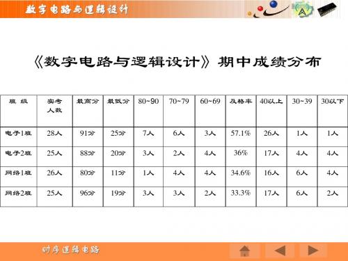
6人 2人 4人 3人
3人 4人 4人 2人
57.1% 36% 34.6% 33.3%
26人 17人 16人 17人
1人 4人 6人 6人
1人 4人 4人 2人
时序逻辑电路
数字电路与逻辑设计
7.1 概述 7.2 时序逻辑电路的分析方法和设计思路 7.4 集成计数器 7.5 寄存器
数字电路与逻辑设计
4 作状态转换真值表
计数脉冲
0 1 2 3 4 5 6 7 8 Q2 0 0 0 0 1 1 1 1 0 Q1 0 0 1 1 0 0 1 1 0 Q0 0 1 0 1 0 1 0 1 0
无论是时序波形图还是状态转 换真值表,都反映了该计数器是 从状态000开始计数,每来一个 计数脉冲,二进制数值便加1, 计满归零。 输入第8个计数脉冲时计满归零 作为整体,该电路可称为模8加 模 计数器 、或八进制 八进制加计数器。
1 1 1 0
0 0 0 1
1 0 0 1
0 1 0 1
1 1 0 1
0 0 1 1
1 0 1 1
0 1 1 1
1 1 1 1
0 0 0 0
分析:图中各位触发器均为上升沿触发的D触发器。由于 分析: 各位D触发器的输入D端与它们各自输出的非联在一起,所 以,F0在每一个时钟脉冲上升沿到来时翻转一次。 F1在Q0由 1变0时翻转, F2在Q1由1变0时翻转, F3在Q2由1变0时翻。
数字逻辑设计第七章(2)D锁存器

RD DOUT[3:0]
Xi Yi Ci
X Y
S
CI CO
锁存器的应用
Si Ci+1
串行输入、串行输出 注意:时钟同步
QD Q C CLK
Xi Yi
时钟控制
再谈串行输入 加法器的实现
Ci
暂存
XY CI CO
S
Si
Ci+1
9
触发器
只在时钟信号的边沿改变其输出状态
正边沿 上升沿
负边沿 下降沿
CLK
Q
15
D锁存器 ——电平有效 D触发器 —— 边沿有效
触发器的应用
利用触发器作为移位寄存器(图1)
思考:能否将触发 器改为锁存器(图2) D
F/F
F/F
D Q Q1 D Q Q
CLK Q
CLK Q
D CLK
Q1 Q
16
CLK D
CLK
(图1)
latch
latch
Q1
DQ
DQ Q
CQ
CQ
(图1)
D触发器的定时参数
QQn+*1==SS++RR’’··QQ
Q —— 当前状态(原态、现态)
Q* —— 下一状态(新态、次态)
S·R = 0(约束条件)
31
J K C
C J K Qm Q
32
SQ
SQ
C 主 Qm C 从
RQ
RQ
逻辑符号 Q
JQ QL C
KQ
1 箝位
功能表
C=1期间,
JK Q
0 1
J的变化只引起 Qm改变一次
CLK=1时, 主锁存器不工作,Qm 保持不变 从锁存器工作,将 Qm 传送到输出端
时序逻辑电路ppt课件

• 状态表
Reset Start B[0] E Sn
1 x xxx
0 0 x x S0
0 1 x x S0
0
X 0 x S1
0
X 1 x S1
0
X x 0 S2
0
X x 1 S2
Sn+1 Init Add Shr Cnt Done
S0 0 0 0 0 1 S0 0 0 0 0 1 S1 1 0 0 0 1 S2 0 0 0 1 0 S2 0 1 0 1 0 S1 0 0 1 0 0 S0 0 0 1 0 0
Start/Init
assign done = (state == S0); S1
//next state function
Cnt
always @(start or e or state) begin !B[0] case (state)
B[0]/Add
S0: if(start) next_state = S1;
S0
Done
!Start
endcase end
Start/Init
S1
//datapath function
Cnt
always @(posedge clk) begin
!B[0]
B[0]/Add
case (state) S0: if (start) begin
S2
E
Shr
!E
d <= x; b <= y;
X Y Start Reset 44 Clk
乘法器
reg [3:0] a, b, d; reg c; reg [1:0] state, next_state, t;
8 Z Done
- 1、下载文档前请自行甄别文档内容的完整性,平台不提供额外的编辑、内容补充、找答案等附加服务。
- 2、"仅部分预览"的文档,不可在线预览部分如存在完整性等问题,可反馈申请退款(可完整预览的文档不适用该条件!)。
- 3、如文档侵犯您的权益,请联系客服反馈,我们会尽快为您处理(人工客服工作时间:9:00-18:30)。
Inputs
Combinational
Storage
Logic
Elements
Next
State
State
Outputs
2
Chapter 7
12
Chapter 7
2、S-R latch
• built with NAND
gates
S_L S Q Q R_L R Q Q_L
S_L 、R_L: active low signals
S_L R_L Q Q_L
0
0
1
1 forbidden
0
1
1
0 set
1
0
0
1 reset
1
1
Last lastQ Q _L hold
H
level
L
coordinate by signal rising edge or falling edge
• clocked synchronous state machine
all memory of the sequential circuit changes only on a clock edge or signal level.
ddpp
Chapter 7 sequential logic design
principles
•state, state variable •latches, flip-flops •analysis •synthesis
sequential circuit
• the outputs depend not only on its current
the stored bit is present on the output Q.
9
Chapter 7
进入亚 稳态
10
Chapter 7
(2) minimum pulse width
S
propagation delay is exist when a transition on S or R input produce a transition on an output signal.
8
Chapter 7
1、S—R Latches
S-R latch built with NOR Function table
gates
SR Q
Q_L
1
0 0 Last Q lastQ_L hold
01 0
1
reset
10 1
0
set
2
11 0
0 forbidden
Q=QN’=Q_L’
S and R : active high signal
state variable: the symbol representation of
state. n state
2n possible
variables
states
• finite-state machine
the states of a sequential circuit is always finite.
SQ RQ
current state
QS
0
0
0
0
0
1
characteristic equation for
0
1
S-R latch:
Q*=S+R’Q (S·R=0)
1
0
1
0
1
1
S=R=1, restricted combination 1 1
next state
R Q*
0
0
1
0
0
1
1
d
0
1
1
0
0
1
1
d
4
Chapter 7
7.1 Bistable Element
1
feedback
2
Q is the state variable
• Output variable:Q,Q_L,且Q_L=Q’ • Two stable state:
Q=0、Q_L=1
Q=1、Q_L=0
5
Chapter 7
analysis with transfer characteri
stable
INV1
metasta ble
INV2
VOUT=T(VIN)
6
Chapter 7
stable VI1=VO2
7
Chapter 7
7.2 Latches and Flip_Flops
• basic building block • be classified as S-R、D、T、J-K types • definition: ① latch:watches the circuit’s inputs
Some important concepts
• state and state variable
state : collection of state variable, contain all the information about the past necessary to account for the circuit’s future behavior.
13
Chapter 7
3、S-R latch with enable
SQ C RQ
forbidden
metastable still exist
14
Chapter 7
4、D latch
the time of active level of S or R must be keeping longer than minimum pulse width, or else the
latch may be go into metastable.
11
Chapter 7
(3) symbol and characteristic equation
3
Chapter 7
Some important concepts
• clock
a clock signal is a signal used to coordinate the actions of two or more sequential units.
coordinate
by signal
continuously and can changes the outputs at any time.
② flip-flops:samples the circuit’s inputs and
changes the output only when a clocking signal is changing.
