安森美电源管理芯片ncp1652设计帮助
LED路灯的散热及驱动芯片介绍_中_

当出现过载或 VCC 电压在 VCC(OFF) 以下的情况时, 控 制 器 工 作 于 两 次 打 嗝 模 式 ,这 种 两 次 打 嗝 或 重 复 打 嗝 模 式 ,可 以 在 有 故 障 的 情 况 下 使 外 部 元 件 的 功 耗 降 低至最小。图 11 给出了重复打嗝模式的运反馈
信号;前馈信号 VFF 是一个直流电压,与 AC 线电压成 正比,由全波整流后 电 压 经 电 阻 分 压、电 容 平 滑 后 得
到,其值在 0. 7 ~ 5. 0V 之间,可以表示为:
VFF
=
2 Vac π
槡2 α
(2)
式中,α 是分 压 比,通 常 为 0. 01; VFF 中 可 能 含 有 二 次
出 低 电 平 使 开 关 管 停 止 导 通 。 这 样 ,基 准 发 生 器 的 输
出可以控制开关管占空比。在上述诸多信号控制下,
输 入 电 流 能 够 跟 随 输 入 电 压 的 变 化 而 变 化 ,达 到 提 高
电 路 的 功 率 因 数 、减 少 谐 波 失 真 的 目 的 。
在 上 述 控 制 下 ,在 正 常 输 入 电 压 和 满 负 载 的 情 况
由于 线 电 压 整 流 后 加 到 PFC 级,为 了 得 到 较 高 的功率因数,和一般 的 功 率 因 数 校 正 电 路 一 样,整 流
期
后 不 能 采 用 大 的 电 解 电 容 器,所 以 加 到 HV ( STARTUP) 脚的 电 压 必 须 另 外 由 图 13 所 示 的 峰 值 充电器( 二极管与大电解 串 联、半 波 整 流 ) 来 供 电,保 持 HV 电压稳定。否 则,当 AC 电 压 过 零 时 HV 脚 电 压 很 低 ,启 动 电 路 可 能 无 法 正 常 工 作 。
安森美半导体提供智能电表解决方案

安森美半导体提供智能电表解决方案近年来,世界各国均发展智能电网,智能电表在这应用中发挥关键作用,可以使用户与电力系统之间实现互动,如一方面帮助电力机构精确了解用户的用电规律,为高峰用电或低谷用电设定差异化的电价;另一方面,用户也可以调整自己的用电计划,节省电费支出。
从智能电表的组成来看,主要包括通信、电源及电源管理、计量及存储等功能模块。
安森美半导体身为应用于高能效电子产品的首要高性能硅方案供应商,提供应用于智能电表各个功能模块的丰富解决方案,如PLC 调制解调器和线路驱动器、放大器、稳压、监控、电压保护、温度传感器、实时时钟、存储器、LCD 背光、I/O 接口、智能卡接口和I/O 扩展器等。
其中,就电源及电源管理模块(参见提供高能效及低待机能耗的AC-DC开关稳压器如表1 所示,在交流-直流电源转换部分,可以选用安森美半导体的一系列开关稳压器,如适合低功率应用的NCP1010/1/2/3/4 自供电单片开关稳压器、适合中等功率应用的NCP1027 高压单片开关稳压器,以及高压门控开关稳压器NCP1050/1/2/3/4/5 等。
以NCP101x 为例,这系列器件集成了固定频率电流模式控制器及典型导通阻抗为11 或22 Ω的700 V MOSFET,提供构建强固及低成本开关电源所需的全部特性,包括软启动、频率抖动、短路保护、跳周期、最大峰值电流设定点及动态自供电(不需要辅助绕组)等。
在正常负载工作期间,NCP101x 以65、100 及130 kHz 中的某一频率开关;而当电流设定点降到低于某个给定值(如输出功率需求消失)时,NCP101x 自动进入所谓的跳周期模式(在此模式下跳除不需要的开关周期),从而提供极佳的轻载能效。
由于进入跳周期模。
安森美半导体推出四款新增补器件扩充功率因数控制器系列

安森美半导体推出四款新增补器件扩充功率因数控制器系列安森美半导体宣布扩增领先业内的功率因数校正(PFC)控制器系列,专为照明、电源适配器、ATX 电源、平板电视和其他电源应用而设计,这四款新器件可促进符合全球新兴能源效率和功率因数标准的高效电源开发。
安森美半导体汽车与电源管理产品部高级副总裁兼总经理威廉思(AndyWilliams) 说:“这些新器件的推出再一次推升了安森美半导体在功率因数控制器领域的领导地位。
通过提供取代业内标准产品的更多性能、更新且更加创新的控制方法和能够节省高效开关电源设计时间与努力的额外功能,这四款新器件加强了我们现有的PFC 产品系列,而为了满足客户持续不断追求更高效电源管理的需求,我们也将持续开发能够帮助他们解决设计挑战的PFC 解决方案。
”器件NCP1605 是一款能够采定频非连续导电模式(DCM,DiscontinuousConductionMode)或临界导电模式(CRM,CriticalConductionMode)工作的强化型高电压和高效率待机模式功率因数控制器,这个器件集成了构筑稳固PFC 段电路的所有功能,NCP1605 可以采PF C 主控端方式工作,确保电源的第二段电路只有在安全情况下才会启动,另外,它还集成了跳周期能力,将待机能耗降到最低,采无铅SOIC-16 封装,NCP1605 每1,000 片预算批量单价为$1.07 美元。
NCP1606 系列为电子镇流器中预先转换,交流电适配器、平板电视以及其他低到中等容量,约达300W 离线转换器应用所设计的CRM 功率因数控制器,这些器件集成了可调整的过压保护,同时内置欠压保护。
NCP1606A 和NCP1606B 带来了完全兼容业内标准器件脚位的直接替代选择,其中NCP1606B 更通过提供更小过压保护电流和更低的电流感测临界值进一步降低功耗,器件采无铅SOIC-8 封装,每。
安森美半导体推出高功率应用控制器,扩展功率因素修正产品系列
安森美半导体推出高功率应用控制器,扩展功率因素修正产品
系列
佚名
【期刊名称】《单片机与嵌入式系统应用》
【年(卷),期】2003(000)005
【摘要】安森美半导体推出创新功率因素修正(PFC)控制器NCP1650,进一步巩固其环球高性能电源管理元件供应商的地位。
NCP1650可为高达3kW的功率系统提供有源功率因素修正,并且是针对分布式电源、数据通信电源,机架型电源系统以及服务器电源等广泛的工业应用。
【总页数】1页(P57)
【正文语种】中文
【中图分类】TM571
【相关文献】
1.安森美半导体推出μ Cool功率MOSFET产品系列 [J],
2.安森美推出高功率应用控制器扩展功率因素修正产品系列 [J],
3.安森美半导体推出高功率应用控制器,扩展功率因素修正产品系列 [J],
4.安森美半导体推出高功率应用控制器 [J], 刘璇
5.安森美半导体推出便携式应用的μ Cool^TM功率MOSFET产品系列 [J],
因版权原因,仅展示原文概要,查看原文内容请购买。
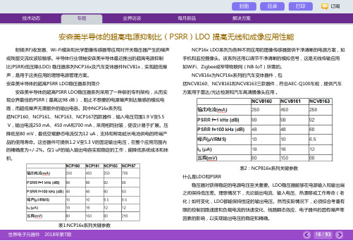
安森美半导体的超高电源抑制比(PSRR)LDO提高无线和成像应用性能
射频(RF)收发器、Wi-Fi模块和光学图像传感器等应用对开关稳压器产生的噪声或残留交流纹波较敏感。
半导体行业领袖安森美半导体最近推出的超高电源抑制比(PSRR)低压降(LDO) 稳压器系列NCP16x及汽车变体器件NCV81x,实现超低噪声,是用于这类应用的理想电源管理方案。
安森美半导体的超高PSRR LDO稳压器系列简介安森美半导体的超高PSRR LDO稳压器系列采用了一种新的专利架构,从而实现业界最佳的PSRR(最高达98 dB),阻止不想要的电源噪声到达敏感的模拟电路,而超低噪声无需额外的输出电容。
其中NCP16x系列包括NCP160、NCP161、NCP163、NCP167四款器件,输入电压范围1.9 V至5.5V,输出电流250 mA、450 mA和700 mA,采用相同封装,使设计易于扩展。
压降低至80 mV,最低空载静态电流仅为12 uA,支持和帮助延长电池供电的终端产品的使用寿命。
这些器件可提供1.2 V至5.3 V的固定输出电压,在整个应用范围内的精确度为+/-2%。
仅1 uF的输入输出电容实现稳定的工作,能降低系统成本和体积。
表1:NCP16x系列关键参数NCP16x LDO系列为各种不同应用的图像传感器提供干净清晰的电源方案,如手机和监控摄像头。
该系列还用以调节干净清晰的模拟信号,这是无线传输应用如WiFi、Zigbee或窄带物联网(NB-IoT)所需的。
NCV816x为NCP16x系列的汽车变体器件,包括NCV8160、NCV8161和NCV8163三款器件,符合AEC-Q100车规,提供汽车方案用于雷达/光达检测和汽车高清摄像头应用。
表2:NCP816x系列关键参数什么是LDO和PSRR稳压器对获得稳定的电源电压至关重要。
LDO稳压器能够在电源输入和输出端之间保持低压差。
理想情况下,无论输出电流、输入电压、热漂移或工作寿命(老化)如何变化,LDO都能保持恒定的输出电压。
安森美半导体电源管理方案
安森美半导体电源管理方案
近年来,手机等便携设备市场持续快速发展。
据预计,手机出货量将从2011年的14亿部增长至2014年的18亿部;其中又以智能手机市场耀眼,受大量低成本Android手机上市推动,同期智能手机出货量将从4亿部增长至6.8 亿部,而且智能手机的半导体元件含量远高于功能型或入门型手机。
与此同时,领先制造商更加重视用户使用体验,其举措之一是在产品设计中选择能够更好配合智能手机等便携设备应用要求及技术趋势的产品及方案。
安森美半导体身为全球高能效电子产品的首要硅方案供应商,针对便携应用提供丰富的解决方案。
本文将重点探讨安森美半导体的高性能、高能效方案如何配合智能手机等便携应用的要求及技术趋势,帮助设计工程师选择适合的元器件方案。
高集成度PMIC简化设计,加快产品上市进程
众所周知,便携设备集成的功能越来越多,从拍照到音视频播放、游戏乃至位置服务等,不一而足。
而随着3G乃至4G网络基础设施的就绪,用户
越来越习惯于透过智能手机等便携设备来以无线方式访问丰富的数据及多媒体内容,需要便携设备嵌入更多更强大的射频(RF)模块。
相应的代价是功率消耗越来越高,而电池容量及技术方面的进展仍然缓慢,便携设备设计人员必须适应这种结合许多功能的高集成度趋势,提供足够长的电池使用时间,同时配合消费者对纤薄外形的需求。
为了应对这些挑战,便携设备设计人员的一项可行策略就是在选择集成多种功能的主芯片组,同时选用高集成度的电源管理集成电路(PMIC),帮助简化设计,使控制电源所需的资源减至最少,并将外形因数保持在可控范围之内。
安森美半导体推出第四款GreenPoint(tm)参考设计
安森美半导体推出第四款GreenPoint(tm)参考设计用于笔记本电脑电源适配器新型90 瓦电源适配器解决方案,能效高达90%,且设计简单安森美半导体(ONSemiconductor,美国纳斯达克上市代号:ONNN)推出第四款GreenPoint(tm)参考设计,用于90 瓦(W)笔记本电脑电源适配器,该参考设计采用单段方法,消除了两段功率处理的负担,提供真正的高能效。
因此,在解决电源适配器的所有电源功能模块的同时,获得低待机能耗,且符合美国加州能源委员会(CEC)、能源之星以及欧洲行为准则(CodeofConduct)要求。
安森美半导体电源转换产品部副总裁AndyWilliams 说:“这个参考设计延伸了安森美半导体在先进电源管理半导体的领先地位至高效笔记本电源适配器。
这经全面测试的笔记本电脑适配器解决方案在开发过程中采用了安森美半导体在高效电源设计的专业技术,便于原设备制造商(OEM)用于向市场提供高能效的终端产品。
”参考设计新型GreenPoint(tm)适配器参考设计的能效为90%。
该设计采用专利的单段拓扑结构,需要的元件数量远少于传统的两段方案。
该参考设计符合OEM 对表面温度和100 微安(μA)以下泄漏电流方面的要求。
为减小输出纹波,并将谐波电流维持在IEC1000-3-2 规定的D 类要求内,该参考设计采用了EnergyRecoverySystemsCorporation 开发的双环纹波/功率因数优化技术,该公司是安森美半导体在这创新适配器参考设计的技术及产品开发合作伙伴。
NCP1651 是该参考设计的主导器件。
该器件是专为50/60Hz 电源系统中通用输入范围内(85Vac-265Vac)工作的有源功率因数校正控制器。
它为中高输出电压要求的隔离交流—直流转换器提供了成本低、元件数量少的解决方案,而且轻易满足50W-250W 范围转换器的IEC1000-3-2谐波要求。
NCP1651 采用乘法器设计专利技术,与传统模拟乘法器相比,操作更精确。
安森美半导体推出用于高能效紧凑型适配器方案的固定频率电流模式控制器
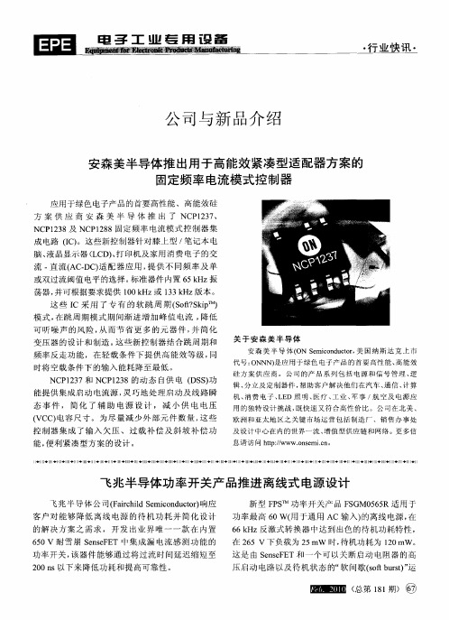
脑 、 晶显 示器 ( C 、 印机及 家 用 消费 电子 的交 液 L D)打
流 . 流 ( . ) 配 器 应 用 , 供 不 同频 率 及 单 直 AC DC 适 提 或 双过流 阈值 电平 的选择 。 准器 件 内置 6 Hz振 标 5 k 荡器 , 并可根据 要求 提供 10k 或 1 3 Hz 本 。 0 Hz 3 k 版 这 些 I 采 用 了专 有 的 软 跳 周 期 ( ot kp ) C S f S iT ? M 模 式 , 跳 周 期模 式 期 间渐 进 增 加 峰 值 电流 , 在 降低 可 听 噪 声 的风 险 , 而 节 省 更 多 的元 器 件 , 从 并简 化
变 压器 的设 计 和制 造 。 些 新控 制 器结 合跳 周 期和 这 频 率反走 功 能 ,在 轻 载 条件 下 提 供高 能 效等 级 , 同
时将 空 载条 件下 的输 入 能耗 降 至最 低 。
关 于 安 森 美 半 导 体
安 森 美 半 导 体 ( N S mi n u tr美 国 纳 斯 达 克 上 市 O e c dc , o o 代 号 : N ̄ ) 应 用 于 绿 色 电子 产 品 的 首 要 高 性 能 、 能效 O t 是 高
机 、 费 电 予 、 E 照 明 、 疗 、 业 、 事 / 空 及 电 源 应 消 LD 医 工 军 航
态 事 件 , 简 化 了 辅 助 电 源 设 计 , 减 小 供 电 电压
( c 电容 尺 寸 。 为尽 量 减 少 外 部元 件 数 量 , 些 vc ) 这 控制 器 集 成 了输 入 欠 压 、 过 载 补 偿 及斜 坡 补 偿 功
-
电 子 工 业 董 用 设 备
・
行 业快 讯 ・
安森美半导体高效电源管理技术助力节能环保
电路 的设计 。 此外 , 虽然 R l o S指 令 已经 在 20 0 6年 7月 1日
实施 , 迄今为止还没有区分元器件是否含有某些物
是人们的主观意识上, 环保节能型” “ 设计已是电源
管理 市场 发展 的大趋 势 。
质的通用标准。 今年 3 , 月 中国《 电子信息产品污染
控制管理办法 》标志着中国 R H 开始全面实施 , oS
以推 动 中国 的绿 色 制造 产业 。
“ 环保节能型” 设计的需求在给半导体产业 带 来 巨大机遇的同时 ,也带来 了重大挑战。在满足政
府 及 相关组 织 提 出的节 能 环保 标 准 和规 范 的 同 时 , 半 导体企 业还 必须 考虑 消费 者 的特定需 求 。作 为业
2 中 国 电源 管理 市场 的挑 战 和 机 遇 、
除 了需要面对上述挑战,整个行业还必须迎接
内领先的电源半导体解决方案供应商 ,安森美半导 体拥有专业的设计队伍及高效 的供应链流程 ,一直
电源技术拐点的挑战。电源管理方案的复杂程度正 致力于研发并提供高效的符合环保要求的电源管理 在 不断提 高 ,因此 总 有一 天 目前 的解 决方 案将 无法 方案 , 在成 功应 对 电源管理 市场 挑战 的 同时 , 为实 现 满足对电源管理 的要求 。 P 以 C为例 , 一方面 C U频 P 环保和节能提供卓越的解决方案。
率 正在节 节 上升 , 另一方 面 , 电流 不断增 加 和 电压却
在不断下降。 丽可供选择的其他方案 , 无论是风扇还
1 、高效率 、 高集成 带来的设计挑战
今天的电源管理市场正处在剧烈变革之中 , 电 各种运作模式下都必须提供更 高的效率 ,例如小于 ( E 和美 国能源之星 ( N R YS A 要求外 C C) E E G R) T 接电源能效大于 8 %的规定。 0 降低谐波 的要求也促
安森美半导体为三星高性能PC提供电源管理方案

安 森美 半 导 体 为三 星 高 性 能 P 提 供 电源 管理 方 案 c
安 森 美 半 导 体 ( 国 纳 斯 达 克 上 市 代 号 :O N 宣 布 , 美 N N) 三 星 电 子 已选 用 其 先 进 的 降 压 控 制 器 为 三 星最 新 高 陛 能 个
器 件 中 ,同 时提 供 标 准 的 和 增 强 的 K E O 功 能 ,减 少 了 外 EL Q ,
培 训 资 料 都 完 全 可 用 。另 外 ,多 种 选 择 卡 使 得 用 户 可 重 组 变 频 器 , 队满 足 将 来 的 需 要 。 此 次 发 布 会 反 应 良好 , 会 场 内听 众 表 现 踊 跃 。演 讲 过 后 , 多 热 心 听 众 对 变频 器 应 用 软 件 硬 件 提 出 问 题 , A O 很 VC N 代 表 耐 心 解 答 交 流 气 氛 极 为 融 洽
芬 兰 v c N变频 器 产 品 介 绍 暨新 产 品发 布会 Ao
四 月 四 日上 午 , 芬 兰 瓦 萨 公 司 北 京 代 表 处 在 2 0 中 02 国 ( 州 ) 国 际 自动 化 展 览 会 会 馆 内 举 办 了 “ 兰 V C N 广 莽 A O 变 频 器 产 品介 绍 暨 新 产 品 发 布 会 ” 。 1 9 年 起 , V C N迅 速 地 成 为 在 多 种 应 用 场 台 , 为 各 93 AO 行 各 业 包 括 民用 领 域 ,提 供 优 质 可 靠 的 变 频 器 产 品 的 十 界 眭 著 名 的 供 应商 。在 此 次 发 布 会 上 , 瓦 萨 公 司 代 表 首 先 简 单 介 绍 了瓦 萨公司 的 c x系 变 频 器 , 后 着 重 介 绍 了 本 次 发 然 布 会 新 推 出 的 N 系 列 变 频 器 。 是 一 种 建 立 在 新 型 硬 件 和 x 这
安森美半导体中高功率照明LED驱动器方案

安森美半导体中高功率照明LED驱动器方案LED的诸多优点已经使其逐步取代白炽灯、荧光灯等传统光源,在小功率应用上越来越多地出现在我们日常工作生活中,而在我们传统定义的20至400瓦的中高功率照明范围内,荧光灯、高强度气体放电灯还是主流。
但随着大功率LED产品的不断推陈出新,模块化的LED灯条、大阵列LED等产品的出现,公路、体育馆、户外大型设施等需要大功率照明的应用场景中也越来越多出现LED产品的身影。
LED照明电路相对设计简单、能集成控制、可方便实现调光、能有效降低电力消耗,所以在强调智能、绿色照明的今天,中高功率LED产品逐步替代高强度气体放电灯(HID)等传统光源已经是大势所趋。
但我们也看到模块化的LED灯条和阵列对电源驱动的要求不尽相同,如何为中高功率LED照明产品提供可靠、高效、灵活的驱动电源方案是设计人员常面临的挑战。
安森美半导体积极推动高能效创新,充分利用在电源领域的丰富经验,提供应用于LED照明不同的领域。
而针对中大功率LED照明应用的不同需求,安森美半导体提供功率因数校正(PFC)控制器、准谐振及固定频率的反激控制器和开关稳压器、集成MOS的降压控制器、半桥驱动及LLC控制器、次级端控制器、集成PFC及PWM的组合控制器等多种控制器及其方案等,以满足不同电路拓扑设计的不同需求。
单段式功率因数校正(PFC)方案功率因数校正(PFC)可有效改善高谐波分量给电源线、断路开关、电力设施带来的压力。
PFC控制器一般可以分为单段式和多段式(常见两段式)两种结构。
单段式(如图1所示)可直接电流驱动,只需单个开关及磁性元件,缺点则是100/120Hz纹波,MOSFET应力更大,占空比更大,功率限制在100-150W。
图1.单段式PFC结构示意图典型的单段式PFC LED驱动方案有如安森美半导体的NCL30000。
这器件使用临界导电模式(CrM)反激架构,以单段式拓扑结构提供高功率因数设计。
安森美半导体基于NCL30000构建的25 W高功率因数单段式LED驱动器参考设计接受90-305Vac宽输入电压范围,能。
安森美半导体携手伟诠电子推出全新世界级的高能效、高密度USB PD电源适配器方案

安森美半导体携手伟诠电子推出全新世界级的高能效、高密度USB PD电源适配器方案NCP1568是一款高度集成的AC-DC脉宽调制()控制器,采纳ACF拓扑结构,包含零电压开关(ZVS),用于要求高功率密度和高能效的高频应用(高达1 MHz)。
它能够无缝过渡到非延续导电模式(DCM),提高轻载条件下的能效,使待机功耗低于30毫瓦(mW),符合全球能效监管标准。
自适应ZVS频率调制提供可变输出电压,优化USB-PD和迅速充电的实施。
可用法阅历证的超结FET或高性能氮化镓(GaN)FET 的ACF拓扑结构,外部器件更少,实现更高密度设计。
NCP1568采纳小型TSSOP-16封装,具有多重庇护功能。
静音跳动功能消退工作时的可闻噪声,这是室内电源适配器应用的一个基本需求。
NCP51530是700伏(V)高频率、高边与低边驱动器,可挺直驱动高性能电源应用中的两个N沟道功率。
其特点是迅速的动态响应,30纳秒(ns)的传扬延迟适合高频工作,而5 ns的传扬延迟匹配确保率先市场的能效性能。
NCP51530提供十分强固的计划,不易受dv/dt(高达50 V/ns)和负瞬态的影响。
伟诠的USB PD控制器WT6615F支持USB PD 3.0规范和QC 3.0,用于USB Type-C DFP下行端口(源)充电应用,通过集成USB PD基带物理层、Type-C检测、并联稳压器、电压和检测、负载开关的MOSFET控制器和8位微处理器,最大限度地削减外部元件数,实现小形状和低物料单(BOM)成本,支持3 V至30 V的宽工作电压范围,无需外部,多次可编程的ROM可用于编辑程序代码及用户配置数据。
两款计划都集成全面的庇护特性,包括自适应输出过压庇护、欠压庇护、过流庇护、短路庇护、电缆压降补偿、ACF开环庇护等,在实现高能效和高功率密度的同时确保高牢靠性。
能效和性能测试按照最新的COC V5 Tier 2标准,待机功耗、平均能效和10%负载能效需达到以下规格。
安森美半导体汽车音响及信息娱乐系统方案
安森美半导体汽车音响及信息娱乐系统方案
过去,汽车娱乐系统基本上指的就是音响系统。
如今,越来越多消费领域的功能正逐步应用到汽车中,使得现代汽车信息娱乐系统已经取代传统的汽车娱乐系统。
当今的汽车搭载了先进的信息娱乐系统,包括导航、音响、远程信息处理、紧急呼叫、USB、蓝牙、SD 卡、HDMI 和视频等。
安森美半导体凭借其汽车电子方面的技术优势和能力,为当今及今后的汽车音响及信息娱乐系统提供一系列的电源管理IC、保护器件、信号调理IC、显示驱动IC、信号处理IC 等系统所需产品。
1. 电源管理方案
1) 用于车载收音机及仪表盘系统的双芯片电源方案
NCV8614B 和NCV8855(图1)是安森美半导体的电源管理单元(PMU),集成了线性稳压器、开关电源、高边开关、缓冲器,以及输入/输出端口。
其高度集成性有助于降低系统成本和体积。
结合使用NCV8614B 和NCV8855,可以为汽车收音机或仪表盘系统提供完整的电源解决方案。
其中,NCV8614B 是多路输出的线性电源管理芯片,其电压自适应功能可自动根据输入电压选择,适用于车载收音机设备和仪表盘系统电源。
NCV8855 可满足一些特色应用中不同可调输出电压、不同电流及不同功能设置需求。
该芯片集成了一路高边开关、一路降压(Buck)控制器、一路内置开关管的2A 输出降压转换器,以及两路线性电源控制器,可为多种负载供电,如车载收音机设备的调谐器、CD 机逻辑电路、音频处理器、CD 机或磁带的控制电路。
2) 带电流检测的有源天线LDO
带电流检测的LDO(低压降线性稳压器)能提供精确可调的电流限值,满。
安森美半导体内外部电源适配器最新解决方案
安森美半导体内外部电源适配器最新解决方案如上所述,在输入功率小于75 W时,外部电源无需PFC,系统主要只是段,其结构暗示图1所示。
这种状况下,通常采纳的是反激式拓扑结构,适配器既能工作在固定频率(FF),也能工作在可变频率(VF)的控制器(特殊是就准谐振模式而言)。
在额定负载和轻载条件下,要同时实现较高能效,关键就在于要采纳能够按照负载情况调节工作模式的智能控制器。
图2:功率小于75 W的电源适配器架构针对这类应用,安森美推出了一系列的PWM控制器解决计划。
其中,就功率介于10 W至50 W范围的应用而言,可以采纳NCP1351和NCP1216等器件。
其中,NCP1351采纳固定导通时光、可变关闭时光模式控制技术,会在负载变低时降低开关频率,可以提供卓越的空载能耗,并在轻载条件下提供最佳的能效表现;当频率下降时,峰值电流逐渐下降到最大峰值电流的大约30%,能够避开发生机械共振,从而大幅消退可听噪声,并保持良好的待机能耗表现。
值得一提的是,安森美半导体推出了基于NCP1351的GreenPointTM 40 W打印机电源适配器参考设计。
这参考设计的待机能耗低于150 mW,而目前常用的40 W打印机在相像状况下能耗约为450 mW。
在额定负载条件下,该设计的能效高达85%;而其采纳的频率反走技术,也令其在高于2 W的轻载条件下能效高于80%。
除了NCP1351和NCP1216,安森美半导体还将推出NCP1217和NCP1380等新器件。
而在40 W至70 W的功率应用范围,也可采纳NCP1271、NCP1219和NCP1288等固定频率控制器(其中NCP1219和NCP1288为新产品,即将推出),还可采纳NCP1377、NCP1337和NCP1380等可变频率控制器。
除了PWM控制器,功率小于75 W的电源适配器中,还可采纳其它的众多安森美半导体器件。
如在反馈环节,可以采纳TL431、TLV431、NCP100和NCP4300(用于其次代恒流恒压适配器)等分流稳压器。
安森美半导体新系列开关电池充电方案应对便携设备充电挑战
安森美半导体新系列开关电池充电方案应对便携设备充电挑战多管齐下保证设备的安全性另一个电池充电的挑战是要保证设备安全性不受影响。
NCP185x系列采用了多种安全措施来实现这一目标,包括正向及负向嵌入式过压保护(OVP)、内部结温传感器及管理,以及外部电池负温度系数(NTC)及JEITA管理,而且可提供事件报告机制,将插入、过压、过热、过冷、充电周期状态、充电开始、充电完成等报告给CPU进行相应处理。
独特的正向及负向过压保护可防止新便携设备受到过压的损坏。
线缆及充电器都是一般商品,在廉价的零配件市场就可以买到,出现故障的可能性很高。
充电源可以是交流适配器(电压达20 V)、计算机USB端口(通常12 V-20 V)、小汽车车载套件(典型值12 V)或卡车(典型值24 V),因此只有强固的正向28 V过压保护才可以保护设备的安全,且在上述所有应用场景下都提供足够的裕量。
NCP185x 系列可提供+28 V过压保护,可防止充电器故障或热插拔时过高的浪涌电压损坏开关充电器件;此外还有一种情况,在出现插口/连接器故障时,VIN和GND可能反向,NCP1852率先提供了-20 V OVP能力以帮助保护正在充电的手机。
NCP185x系列具有电池温度监测功能,可监测4个温度区(根据JEITA规范):冷<+5℃,不充电;正常温度+5℃至+45℃,满额充电;热>45℃,降低充电电流;烫>65℃,不充电,从而确保电池充电过程不会过热、起火和爆炸。
电池温度监测功能是完全可软件编程的。
图4:4个温度区的电池温度监测NCP185x系列还可以将充电操作的变化或意料之外的故障报告给外部FLAG引脚,以便中断充电;应用处理器可以通过I2C启动充电控制及充电周期,且配合报告充电事件。
宽广阵容的NCP185x系列应对不同需求安森美半导体提供丰富的开关电池充电器件产品阵容来应对便携设备的充电挑战。
安森美半导体GaN晶体管——追求更快、更智能和更高能效
安森美半导体GaN晶体管——追求更快、更智能和更高能效采纳GaN设计电源时,为降低系统EMI,需考虑几个关键因素:首先,对于Cascode结构的GaN,阈值十分稳定地设定在2 V,即5 V导通, 0 V关断,且提供± 18 V门极电压,因而无需特殊的驱动器。
第二,布板很重要,尽量以短距离、小回路为原则,以最大限度地削减元件空间,并分开驱动回路和电源回路,而且需用法解调电容。
对于硬开关桥式电路,用法磁珠而不是门极电阻,不要用反向二极管,用法解调母线电容。
此外,必需用法浪涌庇护器件,并通过适当的散热确保热性能,并行化可通过匹配门极驱动和电源回路阻抗完成,当以单个点衔接时,要求电源和信号元件自立接地。
示例:利用GaN设计12 V/20 A 一体化工作站电源一体化工作站正变得越来越轻薄,要求更轻和更小的电源转换器,这通常通过提高开关频率来实现。
传统Si MOSFET在高频工作下的开关和驱动损耗是一个关键制约因素。
GaN HEMT提供较传统MOSFET更低的门极电荷和导通电阻,从而实现高频条件下的更高电源转换能效。
演示板设计为240 W通用板,它输出20 A的负载电流和12 V输出电压,功率因数超过98%,满载时总谐波失真(THD)低于17%。
电源转换器前端采纳功率因数校正(PFC) IC,将AC转换为调整的385 V DC电压。
升压转换器中的电感电流工作于CCM。
升压PFC段采纳安森美半导体的NCP1654控制器。
次级是隔离的DC-DC转换器,将385 V DC总线电压转换为12 V DC输出电压。
隔离的DC-DC转换通过采纳LLC谐振拓扑实现。
次级端采纳同步整流以提供更高能效。
LLC电源转换器采纳安森美半导体的NCP1397,提供97%的满载效率,而同步整流驱动器是NCP4304。
NCP432用于反馈路径以调整输出电压。
演示板采纳GaN HEMT作为PFC段和LLC段原边的开关,提供0.29 m 的低导通电阻和> 100 V/ns 的高dv/dt,因而导致开关和导通损耗低,其低反向复原电荷产生最小的反向复原损耗。
安森美半导体与中国领先 空调制造商达成设计协作
安森美半导体与中国领先空调制造商达成设计协作
佚名
【期刊名称】《《电子与电脑》》
【年(卷),期】2008(000)010
【摘要】高能效电源解决方案供应商安森美半导体(ON Semiconductor)宣布,佛山市中格威电子有限公司(广东志高集团)选用其NCP1027为广东志高空调有限公司节能空调新产品电控系统供电,实现更高的工作效率和更低的待机能耗。
【总页数】2页(P100-101)
【正文语种】中文
【中图分类】TN86
【相关文献】
1.中国空调制造商预测2005年空调价格涨一成 [J],
2.中国在数字化方面处于领先地位是中国纺织业的主要竞争优势——访法国纺织机械制造商协会会长Bruno Ameline和秘书长Evelyne Cholet [J],
3.电力电容工厂中的人机协作——Baxter协作机器人发力电子电力市场提升美国
领先电容制造商生产效率 [J],
4.《电器制造商》杂志参与“2003年中国问题空调调查”活动“2003年中国问
题空调调查”媒体联合宣言 [J],
5.赛格导航中国领先的Telematics车载智能信息终端制造商中国Telematics汽
车在线服务开拓者公司简介 [J],
因版权原因,仅展示原文概要,查看原文内容请购买。
- 1、下载文档前请自行甄别文档内容的完整性,平台不提供额外的编辑、内容补充、找答案等附加服务。
- 2、"仅部分预览"的文档,不可在线预览部分如存在完整性等问题,可反馈申请退款(可完整预览的文档不适用该条件!)。
- 3、如文档侵犯您的权益,请联系客服反馈,我们会尽快为您处理(人工客服工作时间:9:00-18:30)。
When selecting values use low line, full
T
Cout
CT FB
Out A
Out B Rupper
delay
ISpos Rlower RISpos
RISpos
NCP1652 Design Spread Sheet Provided by ON Semiconductor Po = Vo = Vin = Lp = Np/Ns= Pin = 90 19.5 90 600 8 102 W W us V V uH T = 14.286
Suggested
VFFscale acscale RISPOS = RRC= RIAVG =
CM From Soft Skip
Out A
Reference Generator
AC IN VFF AC COMP
D D
G
H
+4.0 V
PWM Logic and Driver
Out B Rupper
Rdelay
Rcomp RVFF2 Ramp Com tLEB
I
Rac2
CM
Ccomp
B
Current Sense Amplifer
0.01 Voltage FF divider ration 0.01 divider ratio 0.1 Current sense shunt 30 (kOhms) ramp comp 100,000 Current scaling resistor (Ohms) 3.40 Vpk
Suggested Range 0.01 RVFF1 Rac2
6.5 V
Vcc UVLO Latch
R
SE T
6.7 k
FB
F
Overload Detect
+
Vcc Mangment
-
150 ms timer and logic
Soft Skip Logic
Q
+5.0 V
S
CL R
Q
LATCH -OFF
Latchoff
OSC Jitt 0.131 27 99,576
Loc. time (deg) 1 10 20 30 40 50 60 70 80 90 100 110 120 130 140 150 160 170 179 Min Max
A Pk shunt voltage 0.005 0.055 0.111 0.167 0.221 0.271 0.314 0.347 0.368 0.375 0.368 0.347 0.314 0.271 0.221 0.167 0.111 0.055 0.005 0.000 0.750
G H Vout I out ac e/a ac e/a buffer (uA) 2.54 27.9 2.49 33.7 2.48 34.7 2.50 32.1 2.55 27.1 2.60 21.1 2.66 15.0 2.71 10.0 2.74 6.6 2.75 5.5 2.74 6.6 2.71 10.0 2.66 15.0 2.60 21.1 2.55 27.1 2.50 32.1 2.48 34.7 2.49 33.7 2.54 28.5 0.75 0 2.80 300
turn-off 3.37 2.98 2.66 2.41 2.23 2.09 1.99 1.92 1.89 1.87 1.89 1.92 1.99 2.09 2.23 2.41 2.66 2.98 3.35 0.00 4.00
Rac1
RVFF1
Rac1
RVFF1
Vcc
Start-Up
Reference
ISpos Rlower RISpos
GND RAMP COMP
IAVG CIAVG RIAVG
RRC
GND RAMP COMP
RISpos IAVG CIAVG RIAVG
RRC
Description of signals A B C D E F G H Peak Shunt Voltage - The instantaneous current signal developed across the current shunt. This is a positive going signal. Isenseout peak - The high frequency current signal out of the current sense amplifier output that is summed with the ac error signal and the ramp compensation signal to provide the input to the PWM. Isenseout avg - The low frequency current signals out of the current sense amplifier. Both currents will be equal, but will result in different voltages. Ac Amplifier, Inverting Input - The voltage signal that results at the inverting input of the ac error amplifier. This signal is the sum of the current sense amplifier output current and the output of the Average Current Compensation amplifier. Feedback input - Error signal from secondary side regulator. This signal is converted into a current in the V-I converter, which has a 1 volt offset. Ac Error Amplifier Output - The voltage output of the ac error amplifier which is required to generate the proper current out of it's buffer. Ac Error Amplifier Output Buffer - This is the current required out of the ac error amplifier buffer, to sum to 4 volts when added to the current and ramp signals (H). Ramp Voltage at Turn Off - The peak ramp compensation voltage is calculated to the right of R 13, once a value is entered. This is the voltage of the ramp compensation signal at the time when the power switch is shut off. This signal is added to the peak current and the ac error amp signal to determine when the switch cycle is terminated. Peak Current + Ramp - This is the sum of the peak switch current (B) when fed into a 16 kOhm resistor, and the instantaneous ramp voltage (H).
Inputs are color coded to data. If some data exceeds the design limits, the like color values should be changed.
Cell contents in Bold Red indicate that the signal exceeds the design limits. Change the appropriate parameters to assure that all signals are in an active
D ac amp invert in 0.07 0.70 1.37 2.01 2.58 3.08 3.48 3.77 3.96 4.02 3.96 3.77 3.48 3.08 2.58 2.01 1.37 0.70 0.07 0.00 4.50
E F Ref mult FB input Iin (uA) voltage 75 3.771 75 3.771 75 3.771 75 3.771 75 3.771 75 3.771 75 3.771 75 3.771 75 3.771 75 3.771 75 3.771 75 3.771 75 3.771 75 3.771 75 3.771 75 3.771 75 3.771 75 3.771 75 3.771 0 1.5 900 4.5
D B Mult Out(V) Isenseout Pos in peak (uA) 0.07 1.4 0.70 13.7 1.37 27.7 2.01 41.7 2.58 55.3 3.08 67.9 3.48 78.6 3.77 86.8 3.96 92.0 4.02 93.8 3.96 92.0 3.77 86.8 3.48 78.6 3.08 67.9 2.58 55.3 2.01 41.7 1.37 27.7 0.70 13.7 0.07 1.4 0 300
