弗列加塑料空滤及油水分离器
发动机油水分离器工作原理和作用

发动机油水分离器工作原理和作用发动机油水分离器(Engine Oil Water Separator)是一种用于发动机冷却系统的装置,它的主要作用是分离发动机冷却液中的油和水,以保持冷却液的清洁和工作效率。
下面将详细介绍发动机油水分离器的工作原理和作用。
工作原理:发动机冷却系统是通过水泵将冷却液循环供给到发动机中,以吸收并带走发动机产生的热量。
在发动机工作过程中,由于活塞与气缸之间的摩擦、油封的磨损等原因,会产生一定量的油渗漏到冷却液中。
这些油污染物会聚集在冷却液中,形成混浊的液体,如果不及时处理,会对冷却系统造成不利影响。
发动机油水分离器通过一系列的过滤装置和分离器来实现对油和水的分离。
其主要工作原理如下:1.过滤:首先,冷却液会通过一个粗滤网,从中过滤掉较大的杂质,如颗粒、纤维和固体微粒等。
2.冷却液和油的分离:接下来,冷却液会进入分离器,分离器内部包含一系列层次分明的滤芯和分离介质。
这些滤芯和分离介质的材料通常是高效的纤维材料或特殊的滤膜,能够有效将油和水分离开来。
在分离器中,冷却液通过滤芯时,油滴会被滤芯上的纤维吸附,并逐渐聚集成较大的颗粒,最终形成油水分离。
分离器中也会有一些装置,如油管和出油口等,用于将分离的油收集起来。
而清洁的冷却液会通过分离器的孔隙,重新流回发动机冷却系统中循环使用。
3.油的排出:当分离器中的油收集到一定量时,可以通过一些阀门或排油口将油排出。
一般情况下,分离出的油会经过进一步的处理,如沉淀、过滤等,最终回收利用或进行处理。
作用:发动机油水分离器在发动机冷却系统中起到了重要的作用,具体表现如下:1.保持冷却液的清洁:油渗漏会导致冷却液的变质,形成混浊的液体。
通过油水分离器,可以有效地将油颗粒和污染物从冷却液中分离出来,使冷却液保持清洁。
2.提高冷却液的工作效率:冷却液在发动机冷却系统中的主要作用是散热。
如果冷却液中存在大量的油渣和污染物,会降低冷却效果,导致发动机过热,甚至损坏。
弗列加LF16170机滤机油滤清器介绍
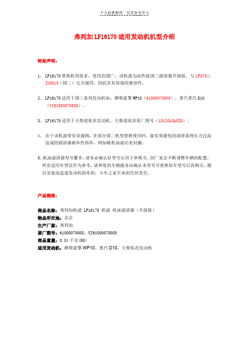
弗列加LF16170适用发动机机型介绍特别声明:1、LF16170替换机型很多,使用范围广,该机滤为高性能国三滤清器升级版,与LF3784、JX0818(国二)完全通用,因此具有很强的兼容性。
2、LF16170适用于国三系列发动机如:潍柴蓝擎WP10(61000070005),重汽重汽D10(VJ61000070005)。
3、LF16170适用于大柴道依茨发动机。
大柴道依茨原厂图号(1012010A52D)。
4、由于该机滤带有旁通阀,在部分国二机型替换使用时,能有效避免因润滑系统压力过高造成的滤清器破坏性损坏,例如呲机油滤芯密封圈。
5、机油滤清器型号繁多,请务必确认好型号后再下单购买。
因厂家会不断调整车辆的配置,所有适用车型仅作为参考,请和您的车辆服务站确认本型号可替换原车型号后再购买,擅自安装而造成发动机损坏的,卡车之家不承担任何责任。
产品规格:商品名称:弗列加机滤 LF16170 机滤机油滤清器(升级版)物品所在地:北京生产厂家:弗列加原厂图号:61000070005、VJ61000070005商品重量:0.84千克(KG)适用发动机:潍柴蓝擎WP10、重汽D10、大柴依茨发动机适用发动机及车型:弗列加 LF16327 机滤,过滤精度为10-30微米,是弗列加为潍柴蓝擎WP10、WD615、重汽D10系列发动机配套的机油滤清器。
安装注意事项:1、注意务必对机油滤清器上座进行必要检查,部分换装过程中易出现旧滤清器密封圈粘连在上座接触面上请及时清理。
2、换装时请先将滤清器内部充满机油,密封圈上也涂油,旋转拧紧至底座密封面即可。
需要注意滤清器密封圈为特殊材料,旋紧时请勿用力过大,以免造成拆卸困难。
为了您的发动机安全请使用正品机滤:机油滤清器的作用:机油滤清器的作用主要就是过滤发动机在工作过程中产生的金属磨屑、积碳、胶状沉淀物、水等杂质,以保持机油的清洁,延长机油正常使用寿命,保护发动机的正常运转。
空压机油水分离器工作原理

空压机油水分离器工作原理
空压机油水分离器的工作原理可以分为三个步骤:分离、排水和过滤。
首先,在空压机排气管道中安装有油水分离器。
当压缩空气通过分离器时,由于油水和空气中的颗粒物具有不同的密度和粘性,它们会在分离器内发生分离。
其次,分离器内部的特定构造和设计使得油水和颗粒物能够沉积在分离器的底部。
这是通过引导气流的方式实现的。
当压缩空气经过分离器时,气流的方向会改变,从而使得油水和颗粒物沉积在底部。
最后,沉积在分离器底部的油水和颗粒物会定期排出。
这是通过分离器上的排水阀来实现的。
当沉积物积累到一定程度时,打开排水阀,就可以将其中的油水和颗粒物排出,以保持分离器的正常运行。
此外,分离器内部还可能配备有过滤器,以进一步过滤空气中的微小颗粒物。
这些颗粒物会被过滤器捕捉,并防止它们进入到空气系统中造成损害。
通过以上的工作原理,空压机油水分离器可以有效地将压缩空气中的水分、油水和颗粒物分离,并保持空气系统的正常工作。
空压机油水分离器使用方法

空压机油水分离器使用方法
空压机油水分离器是一种用于分离空气中的水和油的设备,它可以有效地保护空压机的正常运行,延长设备的使用寿命。
下面我们来了解一下空压机油水分离器的使用方法。
安装油水分离器。
在安装油水分离器之前,需要先将空压机停止运行,并关闭空气进口阀门。
然后,将油水分离器安装在空气管道上,注意安装方向应与箭头方向一致。
最后,将油水分离器的排水口连接到排水管道上。
调整油水分离器的排水时间。
油水分离器的排水时间应根据空气压缩机的使用情况进行调整。
一般来说,排水时间应设置为每小时排水一次,排水时间为5-10秒钟。
如果空气压缩机使用频率较高,排水时间可以适当缩短。
定期清洗油水分离器。
油水分离器在使用一段时间后,会积累一定量的油污和水垢,影响其正常工作。
因此,需要定期清洗油水分离器。
清洗时,先关闭空气进口阀门,然后打开排水口,将油水分离器内的污物排出。
空压机油水分离器的使用方法非常简单,只需要按照上述步骤进行操作即可。
使用油水分离器可以有效地保护空气压缩机,延长设备的使用寿命,同时也可以减少对环境的污染。
因此,建议广大用户在使用空气压缩机时,一定要配备油水分离器。
AFF

注)带托架的隔板不可安装。 请使用附属的托架。
可选项追加 ( ) AMG□C,AFF□C,AM□C,AMD□C AMH□C,AME□C,AMF□C
5 追加: 种
压差开关
1.6MPa规格
氟橡胶规格
带压差开关(AC125V, DC30V) 带压差开关(DC30V) 脱脂洗净、白色凡士林规格
AMH+AME+AMF ※仅C型可模块式连接。
AMF350C 3/8, 1/2 132 18 98 90 5 90 10 150 80 28 8 7 7 14 7 12 50 95 34 80 5 2.3
57
外形尺寸图 AMF450C, AMF550C
P D Q
除臭过滤器 AMF 系列
M T
A B
E R
D N
U
L
托架 (附属品)
øW
K
V
J
进
出
7 O形圈
NBR
JIS B2401G35 JIS B2401G35 JIS B2401G35 JIS B2401G35 JIS B2401G35
1个
1个
3个Βιβλιοθήκη 3个5个56
AMF 系列
外形尺寸图 AMF150C~AMF350C
P Q
T
S
R
F
E
D
N
U
L
托架
(附属品)
O
M
øW
K
V
J
IN
OUT
A B
I C
维护空间 G
(mm)
型号
接管口径 A B C D E F G
托架相关尺寸
I N J K U V L MWO P Q R S T
陕汽德龙FC产品介绍

销销 售售 公公司司
(4)驾驶室外部: 导风板和保险杠独立安装,在正面上的导风板带有踏板和手
柄,用于清洁挡风玻璃。刮水器电动机和防水导线从车外安装; 带有泵和水面指示器的13升挡风玻璃清洗器。
半高顶驾驶室可选装顶导流罩,高顶可选用顶侧导流罩。在 运输集装箱等货物时可降低风阻,降低燃油消耗。
德龙FC结合了最大车身长用空间。对驾驶员而言,意味着宜人的 工作环境,最佳化的操纵以及布置合理的仪表,非常舒适。在长 途运输的驾驶室有舒适的便于操作的卧铺。圆角边的斜挡风玻璃 和最佳的空气导风板可保证非常流畅的空气动力性,这是较少的 尘土积累和较好的空气动力的先进的空气动力性设计,是目前国 内驾乘空间最大的车型。不论是从设计、还是性能角度都是与国 际先进水平相当的产品。
自卸车
混凝土搅拌车
1种
7种
共计:29种
运油车 2种
07年12月及08年1月份提报的17种公告
销销 售售 公公司司
销销 售售 公公司司
销销 售售 公公司司
3、德龙FC系列重卡主要配置状态
序号 1 2 3 4 5 6 7 8 9 10
配置 康明斯ISM系列发动机 (11L全电控) 法士特变速器(9、12、16档,同时可选超速档)
4.8
5.73
18100 16680 13730
4×2系列车型 6×4系列车型
销销 售售 公公司司
进气:漩流式进气扁管+弗列加空滤,完全保证进气质量,延长发动机寿命。
最大程度满足了发动机工作的空气量需求,充分发挥出 发动机的能力,达到了节约燃油的效果。
销销 售售 公公司司
车架 : 牵引车系列采用国际先进的变截面车架(前端 940mm,后端为780mm)
Racor FBO-10和FBO-14燃油滤芯 水分离器应用说明说明书

FBO-10 and FBO-14Fuel Filter/Water SeparatorApplicationThe FBO assembly is specifically designed to meet the filtration requirements of today’s high pressure common rail dieselinjection systems. The unit is used for fuel dispensing pumps or as a primary fuel filter/water separator on large diesel engine applications.Racor’s new FBO-10 and FBO-14 filter assemblies were designed to meet the toughest conditions and offer ease of filter changeouts. The FBO assembly can flow from 10 GPM (38 LPM) to 75 GPM (284 LPM), depending on which model, the element, and the type of fuel to be filtered.The assembly features a “locking ring collar”, which attaches the filter housing to the aluminum die cast filter head with four bolts. The slotted “locking ring collar” allows maintenance personnel to hand loosen the four collar bolts, rotate, and lower the bowl assembly for element changeouts. With a new element installed, simply raise the bowl and rotate into position on the locking ring and hand tighten evenly (evenly torquing the 4 closure bolts to 100 lb-in is highly recommended).The closure hardware consists of stainless steel nuts, bolts, and washers with metal hand knobs for ease of maintenance. No wrenches or other special tools are required, allowing one person to easily change the filter element (no V-band clamps are used).How They WorkThese versatile fuel filter/water separator assemblies have three element options to meet various requirements. For fuel dispensing applications the filter water separator element is recommended.The filter water separator element removes contaminants and water from biodiesel, biodiesel blends, diesel fuel, gasoline, and other hydrocarbon fuels. The filter separator allows water to be removed from the fuel stream.Microfilters are recommended to be used on engines to protect the OEM supplied fuel system.Silicon treated cellulose microfilters remove particle contaminants down to one micron. Microfilters can also be used before filter water separators to extend life.Absorptive filters absorb water and filter contaminants from diesel fuel and other hydrocarbon streams. The filter separator element is recommended so water can be removed from the fuel stream.Features• Die-cast aluminum head • Steel filter bowl assembly • Powder coated components • “Locking ring collar” - no V-clamps• 1.5” NPT inlet and outlet • D esigned to withstand 150 PSI maximum pressure at 240o F • Manual drain valve • Manual vent valve • Sight GlassParker Hannifin Corporation Racor Division P.O. Box 3208Modesto, CA 95354 USA Tel: 800-344-3286Fax: 209-529-3278/racor e-mail:****************Bulletin #7589April 2007© All rights reserved.8.60”Manual VentDifferential Pressure Gauge1.5” NPT Inlet and OutletTopViewFBO-1018.32”FBO-14Manual Drain ValveSight Glass or Optional Water Sensor Probe FrontViewHow To Order* Element is factory installed in the assembly.。
经典福克斯油水分离器更换教程

经典福克斯油水分离器更换教程首先,我们要拔出车辆钥匙,并断开车辆的油水分离器保险丝或断开车辆电源,避免在拆卸油水分离器时油水分离器动作泵出汽油。
接着,拆除后排座椅的坐垫以及油水分离器上的盖板,此时便可以看到油水分离器总成。
油水分离器总成被一个黑色的卡环固定,拆除油水分离器上的线插以及油管后使用专用工具方可拆卸此卡环。
拆卸卡环后可取出油水分离器总成。
把新的汽油滤清器组件替换旧的汽油滤清器上的相应部件。
把更换好燃油滤清器的油水分离器总成装回到油箱中。
最好在燃油水分离器的密封胶圈上涂上凡士林润滑,避免密封胶圈扭曲后密封不严造成燃油或者燃油气体泄漏。
然后,装上油水分离器的固定卡环,并用专用工具按照维修手册上的标准扭力预紧卡环。
最后,装上油水分离器线插以及油水分离器上的燃油管即可试车检查是否存在泄漏,如无泄漏则可安装座椅,有泄露的话则要重装密封胶圈。
汽油滤清器是装在油箱旁边的油管中,主要是过滤汽油中的杂质,4S店会要求4万公里更换,但从实际的使用中,现在的汽油都比较
干净(除非加油时加了油底或者有油槽车在放油),一般用6万公里
都没问题,当然你也要根据发动机的情况而定,如果油路不通畅也应该换的。
弗列加 空滤计算
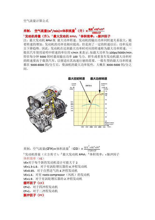
空气流量计算公式米制:空气流量m³∕min=体积流量1(升)×速度2×VE3×PF41000×CF1发动机排量(升);2最大发动机RPM;3体积效率;4脉冲因子注:最大发动机RPM既最大功率转速。
发动机的输出功率同转速关系很大,随着转速的增加,发动机的功率也相应提高,但是到了一定的转速以后,功率反而呈下降趋势。
因此,发动机在达到最大功率时对应的转速称为最大功率转速。
一般在汽车使用说明中转速的单位用r/min来表示,如最大功率为100ps/5000r/min,即在每分钟5000转时最高输出功率100马力。
轿车或者客车发动机最大功率时的转速要高于载货汽车,以便适应其高速行驶的需要。
一般车型的最大功率转速都在5000-8000转/分左右,柴油机的最大功率低些,大概在3000-5000转/分之间。
英制:空气流量CFM=体积流量1(CID)×速度2×VE3×PF41728×CF1发动机排量(立方英寸);2最大发动机RPM;3体积效率;4脉冲因子体积效率(VE)VE=对于每个新的发动机设计可能大于2VE=1.3-1.8,对于有涡轮增压器的4冲程发动机VE=0.85,对于自然送气的4冲程发动机VE=1.4,对有roots-compressor(风机)的发动机VE=1.9,对于有涡轮增压器的2冲程发动机循环因子(CF)CF=2,对于四冲程发动机CF=1,对于二冲程发动机脉冲因子(PF)仅用于具有自然送气和少于3缸发动机PF=4,一缸PF=2,两缸PF=1.33,三缸。
陕汽德龙FC产品介绍
销 售 公 司司 销 售 公
1、产品情况 目前康明斯车型产品覆盖:牵引车、自卸车、搅 拌车、载 货车、厢式运输车、仓栅车、运油车;后期根据 市场情况,将 继续设计、开发新产品,增强产品优势,满 足多变的市场需求。 2、公告情况 截至147批公告,康明斯重卡国三常用公告共计29种:
车 型 公告数量 牵引车 19种 自卸车 1种
共计:29种
混凝土搅拌车 7种
运油车 2种
销 售 公 司司 销 售 公
07年12月及08年1月份提报的17种公告
销 售 公 司司 销 售 公
销 售 公 司司 销 售 公
3、德龙FC系列重卡主要配置状态
序号 1 2 3 4 5 配置 康明斯ISM系列发动机 (11L全电控) 法士特变速器(9、12、16档,同时可选超速档) 进口ZF8098转向机 进口Φ 430单片式离合器,混凝土搅拌车配进口Φ 380双片式离合器 德龙加长加宽驾驶室、德御驾驶室
采用带超速档变速器。
销 售 公 司司 销 售 公
12档变速箱
销 售 公 司司 销 售 公
欧二
4×2系列车型 发动机功率:340、380、405、440马力 6×4系列车型 发动机功率:340、380、405、440马力
欧三
4×2系列车型 发动机功率:345、385、420马力 6×4系列车型 发动机功率:345、385、420马力
ISMe345 30
345/1900
1710/1200
125/147
销 售 公 司司 销 售 公
二、FC系列牵引车
Fc系列牵引车是高速、高效、节油的物流先锋,其完 美的动力传动系统匹配能够满足不同的运输需求。发动机的功
率可以根据装载质量、运输条件进行选择;
2012上海弗列加新产品介绍
PM -95%
13 years
12 10 8 6 4 2 0
Euro 0 Euro 1
-43%
g/kW.hr
-12% -29% -56%
Euro 2
-30%
-33%
Euro 3
-80%
Euro 4
-43%
Euro 5
Euro4
满足欧四的技术途径
0.18
பைடு நூலகம்0.16 g/kWh 0.14
Euro 2
0.12
水位传感器,通 过电路布置,提 醒使用者放水保 养,避免因未及 时放水造成喷油 嘴堵塞等不良现 象。
上海弗列加公司 为特殊的客户要 求,可以专门增 加燃油加热器
底座的两进两出的油 口,便于客户在整车 上的安装,(左置或 右置),方便客户的 油路连接。
透明集水杯,可 以明显看到被分 离出来的水,便 于客户及时放水, 使滤清器始终保 持最佳工作状态, 保护发动机正常 运转。
底座上的手泵,便于客户在更换保 养油水分离器后排除油路中的空气 使滤清器中充满燃油,保证滤清器 的过滤顺畅,和发动机的正常使用。
弗列加产品
高精度大流量滤清器
Stratapore滤纸:深层过滤,是唯一既不 缩短使用寿命(容灰量),又提供极高过 滤效率的精细过滤介质。多层高容灰量的 滤清介质能够延长滤清器的使用寿命,延 长维修更换周期。
燃油滤清器:采用Stratapore 滤纸,深层过滤,Stratapore 滤纸是唯一既不缩短使用寿 命(容灰量),又提供极高 过滤效率的精细滤清介质。 多层高容灰量的滤清介质能 够延长滤清器的寿命,从而 延长了维修更换周期。
燃油加热器:采用PTC加热 元件,最大功率250W,有 效地避免了燃油因温度过低 而堵塞滤清器,使得发动机 更容易启动并减少了发动机 系统能量的耗损。
弗列加塑料空滤及油水分离器
更大的折高 Higher pleat height
30%过滤面积的 增加
30% filter area increased
小折高
Small pleat height
SFG
SFG
额定流量: 270m3/h
额定流量: 900m3/h
额定流量: 1200m3/h
额定流量: 1500m3/h
额定流量: 1900m3/h
SFG
m3/h) A753 AH24174 AH24179 AH8817 AH8822 270 900 1200 1500 1900 (mm) 322 400 420 525 525 (mm) 187 286 324 350 392 (mm) 76 110 130 178 178
Filter Media Contact
弗列加 FG Inc. 特有的 Exclusive 专利的 Patent 过滤介质 Media 满足欧Ⅲ 欧 满足欧Ⅲ/欧Ⅳ排放需求
高性能滤纸
混合纤维 Cellulose/synthetic 天然纤维 Cellulose Stratapore滤纸 滤纸 Stratapore
120℃/24hr
高温试验后,筒体任何部位未发现变形现象。 但为了延长空滤器使用寿命,建议长期工作环境温度应低于80度
-40℃
试验过程:筒体在-40 ℃ 条件下放置24小时,再用 535g重的铁球,从1000mm 高处自由落体,砸到壳体 上指定的位置 。
SFG Advantage of new filter of SFG
FX系列油水分离器 维护和操作手册说明书

FOX ENVIRONMENTAL SYSTEMSMaintenance and Operation ManualOil/water SeparatorThis Manual is the property of the owner operator.Please ensure you pass this to the relative person.This Manual is to be read by all staff producing Tradewaste on the site. Unit 2 /8 Dual Av, Warana Qld 4575 Australia Ph: 5437 8455 Fax: 5437 8488TABLE OF CONTENTS1. The Fox/Oil Water Separator2. Model Compatibility3. Installation4. Operation & Maintenance4.1 Recommended Weekly Maintenance4.2 Quarterly Service5. Trouble Shooting and Fault Finding6. Product Warranties1. The Fox Oil/Water SeparatorThe Fox Series FX separators are enhanced gravity separators and incorporate a Bio-Tube®filtration media pack to promote coalescing of oil droplets and enhance floation separation from the water in accordance with Stokes Laws. The design of the tube pack offers a large surface area for the interruption of flow through the unit with the spiral construction of the tube promoting an upward flow of oil particles.The units will be supplied with a low voltage pump motor control station. There are several options available:Model X1 – Allows Auto/Manual Pump ControlModel X1IS - Intrinsically Safe Control StationModel X2 - Provides for a High Level Alarm in the Holding Tank.Model X2IS - Intrinsically Safe Control StationModel X3 – Provides a Non-Resetable Run Meter (required by some councils)Model X3IS - Intrinsically Safe Control StationAll units are manufactured from 304 Stainless Steel as standard and are fully seal welded. A removable lid ensures that rain or hose water cannot enter the tank in normal circumstances. The lid is vented and has provision for locking. An option is available for the unit to be manufactured from grade 316 Stainless Steel when they are to be used for extremely aggressive waste or salt water applications.The basic design philosophy for each model is typical however the physical size, retention time and tube pack mass for each model increases with the treatment rate of the unit.The Models are designated as follows:▪Model FX1000SS …….. 0.28 l/sec (1000 l/hr)▪Model FX1500SS …….. 0.42 l/sec (1500 l/hr)▪Model FX3000SS ……. 0.85 l/sec (3000 l/hr)▪Model FX6000SS ……. 1.7 l/sec (6000 l/hr)▪Model FX10000SS…… 2.8 l/sec (10000 l/hr)▪Model FX15000SS…… 4.2 l/sec (15000 l/hr)Each Model will be supplied with a Fox Diaphragm Pump, ASM Diaphragm Pump, or a Mono Helical Rotor Pump (where allowable by Local Authorities). Dual diaphragm pumps may also be supplied where suitable.2. Model compatibilityThe Fox Series FX Separator is ideally suited to applications that have the potential to generate waste water containing free floating hydrocarbons in suspension.Typical applications for the separator include but are not limited to the following:▪Vehicle Washdown Areas▪De-greasing Bays▪Mechanical Workshops▪Oil Storage Areas▪Vehicle Hardstand AreasCorrect sizing of the Separator, Pump and Holding Tank and the use of “Quick Break” detergents will provide a system that will treat oily water to a standard that is suitable for discharge into Local Government Tradewaste Disposal Systems.3. Installation InstructionsIt is important to ascertain the requirements of the Local Authority responsible for the installation of pre-treatment systems to ensure that the proposed installation will fulfil their individual requirements.It is the Installers responsibility to ensure when installing any Intrinsically Safe Equipment, it must be installed to the relevant and current Australian Standards for Hazardous Zones.For Information on Hazardous Zones, Placement of Systems and Control Panels etc, contact the Design Engineer on the project drawings.At this stage it is assumed that the Holding Tank has been installed and a bunded concrete pad has been provided for the Separator Installation. Provision should be made for this area to drain back to the Holding Tank.Please refer to the drawings relevant to the Fox Oil/Water Separator and pump being used.▪Model FX 1000 SS …….. A4-INST-1020▪Model FX 1500 SS …….. A4-INST-1021▪Model FX 3000 SS ……. A4-INST-1022▪Model FX 6000 SS ……. A4-INST-1023▪Model FX 10000 SS ……. A4-INST-1025▪Model FX 15000 SS ……. A4-INST-1026Refer to the relevant drawings for the Control Box connection details.▪Model X1 …….. A4-INST-X1▪Model X2 …….. A4-INST-X2▪Model X3 ……. A4-INST-X3▪Model X1IS ……. A4-INST-X1IS▪Model X2IS ……. A4-INST-X2ISFollowing is a step by step procedure for the installation of the Separator, Pump and Control Box. Careful attention should be paid to the items marked as they will affect either the operation of the unit or the safety of personnel.1.Install the pump suction line in the holding tank with a barrel union to enable dismantlingvia the manhole for service. Install a foot valve if a Mono pump is being used. No foot valve is required for the diaphragm pumps as they are self priming.2.Remove the Separator lid; this is done by releasing the over-centre lock, lifting and slidingthe cover away from the locking end. When the lip of the cover clears the lip of the tank the lid can be removed. Supplied loose inside the unit are the legs for the stand, waste oil extension pipe, gate valve(s) for the separator tank and the Holding Tank float switch(es).3.Lift the tank out of the stand. Fit the legs onto the stand, finger tightening the locking bolts.4.Place the stand in position. To ensure correct operation of the Separator, the unit must beinstalled in a level plane in all directions.Using a builder’s level, adjust the legs so that the stand is level in both planes then tighten the locking screws.ing Dynabolts, Chemical Anchors or other suitable corrosive-resistant fixings, anchor thestand utilising the pre-drilled 10 mm dia. holes in the feet. Re-check the levels and adjust if necessary.6.Fit the tank into the stand.7.Fit the gate valve to the tank drain using Teflon tape or suitable thread sealant. Make surethat the valve is closed.8.Install the waste oil extension pipe to the skimmer outlet. The pipe should not be glued tothe adaptor to facilitate removal of the waste oil collection vessel.9.Place the pump in position and fix to the concrete pad using corrosive-resistant fixings.Electrical regulations require that the pump motor is to have a 500mm clearance from the separator unit and holding tanks.10.Install interconnecting pipework between the pump and the separator inlet. Barrel unionsshould be installed on either side of the pump to facilitate easy removal for servicing. Install sample points as required by the Local Authority.11.Connect the outlet pipe of the separator to the trade-waste (sewer) system. Install samplepoints as required by the Local Authority.Connections to sewer system must be made by a licensed plumbing contractor and with the approval of Local Authorities.12.Supply and install a waste oil collection vessel. The waste oil collection vessel must be clearand have provision for a screw cap to be fitted.13.Mount the Control Box adjacent to the pump and near a 240V 10Amp GPO.Any electrical work required must be carried out by a licensed electrician.14.Install Activation Float Switch in the Holding Tank. Attach to the suction line using heavyduty cable ties and ensure that sufficient lead is left to enable removal of the suction line for servicing. Position to ensure clearance from bottom of tank as per installation drawing.Draw cable through 32mm conduit to Control Box location. The float operates on low voltage and is connected to the terminal strip in the Control Box via the gland in the bottom of the unit. Refer to the Control Box installation drawing for connection details. For Model X2 & X3 Control Boxes, repeat procedure for High Level Float Switch.15.Plug the Control Box into the GPO and the pump power lead into the Control Box outlet.16.Fill the Separator to the level of the discharge weir. Ensure that the level in the HoldingTank is well above the pump pick up point before testing. If a Mono pump is being installed it must be primed with water.17.Select the manual run position on the Control Box and turn the power on at the GPO. Thepump will start and transfer water into the Separator. Ensure that the Oil Skimmer is above the water level. The top section of the skimmer pipe slides out from the main pipe. When the water flow through the Separator has stabilised the Oil Skimmer should be adjusted to3 mm above the water level with the pump running.18.The Separator is now ready for work. Turn the Control Box Selector Switch to the Autoposition.4.Operation & MaintenanceProper maintenance of the Oil/water Separator and associated equipment will ensure that the unit continues to perform the function for which it has been installed.The Separator will provide effluent of a quality acceptable for release to sewer at the approved flowrate. Increasing the flowrate beyond this will affect the efficiency of the system. ‘Quick Break’ detergents must be used for the System to operate efficiently. Solvent based detergents may affect the warranty.Documentation of all pre-treatment facility operations, including products and residues removed should be kept in accordance with Australian Standards.Maintenance of the unit should be undertaken at the following regular intervals:-WeeklyQuarterlyNote: These are the recommended maintenance intervals for typical site requirements. The period should be reduced in accordance with the volumes and pollutant loadings of the effluent being treated.4.1 Recommended Weekly Maintenance.1.Remove the Separator lid; this is done by releasing the over-centre lock, lifting and slidingthe cover away from the locking end. When the lip of the cover clears the lip of the tank the lid can be removed.2.Inspect the Separator and ensure that there is no floating debris that can create a blockage.3.Check the level in the waste oil collection vessel. If full, remove the extension pipe from theadaptor and place a screw cap on the oil container. Arrange for proper disposal of the waste.4.Inspect and clean all collection points and silt baskets as required.5.Turn the Separator Controller selector switch to manual and ensure that the pump starts,that the effluent flow through the unit is steady and that the Oil Skimmer pipe is approximately 3 mm above water level.6.Check the flow through the final filter bags.7.Return the selector switch to Auto.8.Inspect the unit and all pipe connections for leaks or physical damage that could affect theoperation.9.Replace the Separator lid and lock if required.4.2 Quarterly Service.Fox Environmental Systems recommend that the quarterly service to the unit is performed by a qualified service technician. All Fox recommended Service agents are able to provide a Fox Service Authorisation Number.1.Perform steps 1-4 & 8 above.2.Isolate the Separator Controller at the GPO and remove the plug.3.Adjust the Oil Skimmer to a point just below the water level to remove any build up of oilon the water surface.4.Drain the sludge from the hopper via the gate valve into a suitable container and dispose ofin a proper method.5.Drain any remaining effluent from the Tank back to the Holding Tank.6.Remove the Tube Pack from the unit and clean thoroughly. Ensure that any run-off isreturned to the Holding Tank.7.Thoroughly clean the Separator internally.8.Refit the tube pack. Ensure that the sludge hopper is fully covered to stop bypass occurring.9. Inspect the final filter bags and replace as necessary.10.Lift the Oil Skimmer pipe to a point above the water level and fill the unit with clean water.11.Check the level of sludge in the Holding Tank. If necessary arrange for the tank to bepumped out and the contents disposed of.12.Check operation of the pump float switch. Be sure that the float is free to move with thewater level and that the contacts change over when the float is lifted.Note: The Holding Tank of a trade-waste system is a confined space and must not be entered without proper precautions being observed. In a properly installed system all regular maintenance activities should be able to be carried out through the access hole in the tank.1.Prime the Pump (if required) and check that the water level in the Holding Tank is sufficientto run the unit.2.Plug the Separator Controller into the GPO and turn on. If the pump does not startautomatically, lift the float in the Holding Tank (use a wire hook or similar) and the pump should run. Let the float down; the pump will shut off automatically when the low level is reached.3.When the effluent flow through the unit becomes steady adjust the Oil Skimmer to 3 mmabove the water level.4.Replace the Separator Lid and lock if required.5. Trouble Shooting and Fault FindingNote: Electrical fault finding must be done by a licensed electrical contractor. Symptom Cause RemedyNo flow to Separator. ∙Mono pump not primed∙Pump diaphragm damaged.∙Pump check valve faulty.∙Suction pipe below sludge level.∙Suction pipe blocked.∙Foot valve blocked.∙Prime pump∙Service pump.∙Service check valves.∙Pump holding tank out.∙Remove obstructions.∙Service foot valve.Pump not running. ∙Low level in Holding Tank∙Float switch jammed.∙Controller switched Off.∙Motor overload tripped. ∙Pump runs with rising float. Lift float. ∙Ensure switch is free to lift with water level.∙Check power is on, & selector switch is on Auto or Manual. Return to Autofor running.∙Reset overload.System will notswitch on.∙Float switch jammed.∙No power to Controller.∙No power to pump.∙Pump running but not pumping. ∙Ensure float switch is free to lift with water level.∙Check power is on, & selector switch is on Auto or Manual∙Check electrical connections and ensure power is available at pump. ∙Refer “No flow to Separator” above.System will notswitch off.∙Float switch jammed.∙Pump not pumping. ∙Ensure switch is free to fall with water level.∙Refer “No flow to Separator” above.Water in Waste oil vessel. ∙Oil skimmer set too low. ∙Adjust skimmer with pump running to3mm above water level.Oil in dischargestream.∙Oil skimmer set too high.∙Incorrect detergent ordegreaser used.∙Excessive heavy oil loadsintroduced into waste stream. ∙Adjust skimmer with pump running to 3mm above water level.∙Use only quick break detergents.∙Pure oil should not be run through the unit.Pump Motor overload trips continuously. ∙Motor starts/stops toofrequently∙Power supply voltage too low ortoo high.∙Holding Tank too small.∙Floats set incorrectly.∙Check voltage.FX Series Oil/Water Separator | 10/06/2021 | Page 9 of 96. Product WarrantyAll products that are supplied by Fox Environmental Systems Pty Ltd (Fox) are warranted to the original owner (not necessarily the purchaser) of the equipment in accordance with the following Limited Warranty. The warranty is only valid when the system is operated and maintained in accordance with the manufacturer’s instructions. If service of the system is not carried out on a regular basis the warranty of your system will be affected.The warranty offered is for the repair or replacement of any part or component manufactured by Fox or their subcontractors that fails due to defects in materials or workmanship for a period of 12 months. To obtain service under this warranty the owner should contact Fox Environmental Systems and advise the nature of their concern, the model and serial number of the unit and the date of purchase. If required the component must be returned at the senders’ expense. A replacement item, which at the discretion of Fox, may be the original component following repair, a reconditioned or new item, will be returned at our expense. Should it be determined that the part is not covered by warranty the owner will be responsible for the payment of any costs involved in the supply of replacement parts, including shipping and handling.All components supplied under this warranty will be covered by a further warranty equal to the remainder of the original limited warranty or 90 days, whichever is the longer. All components replaced under warranty become the property of Fox Environmental Systems Pty Ltd and may be used for whatever purpose they deem suitable.The warranty will be void if the equipment is not installed as per manufacturer’s instructions. Warranty will also be void if water pressure exceeds 1400 kPa. The warranty is only valid when the system is operated and maintained in accordance with the manufacturer’s instructions, and service of the system is carried out on a regular basis. The Commissioning-in report must be completed, signed & returned to Fox Environmental SystemsNote: The use of pipes smaller than the port size of the pumps will void the suppliers’ warranty.This warranty does not cover consumables or any damage arising from improper selection of materials, faulty installation or misuse.What are Consumables?1.The final filter bags.。
油水分离器安装、调试、操作规程及维护保养的操作规程

油水分离器安装、调试、操作规程及维护保养的操作规程1、该油水分别器可直接安装在含油污水流经的通道上,把污水出口对准油水分别器的进口即可,与其它设备可用管道连接。
底部的排污管线与污泥脱水装置连通,如未配污泥脱水装置可直接排入排污管;2、无动力箱式隔油器安装时必需调整其水平位置,不得有误差;3、第一次使用前,应先把设备注满自来水,直到出油口只出油不出水为止。
4、设备安装后,请不要随便乱动,否则将影响出水水质。
5、每天使用后,应将进水口过滤网上的杂物倒掉,并清理洁净。
(餐饮业应用热水冲刷滤网上的油污,以免堵塞滤网,影响进水。
假如是用泵提升进水,请每天清理水泵进水底阀旁污物,以免堵塞泵阀,影响进水流量。
6、每天使用后,应将杂物筐每天提出挂油倒垃圾,并将水上浮油去除掉,箱体每2周清扫一次,将粘在隔板金属外表的油污用刀刮掉,底部垃圾要求去除洁净。
清理完毕恢复原状。
7、当油水分别器的出水、排水管堵塞时,将箱盖罩拿掉,因有臭气溢出,应快速清通,清通后将排水口快速盖上。
8、在使用过程中应定期冲洗设备内部,一般每半月冲洗一次,或视状况而定。
篇2:柴油压风机操作规程一、压风机开机前的检查和预备:1、检查各紧固部位有否松动,是否处在正常状态。
2、本机使用HS-13(冬天用)、HS-19(夏天用)压缩机油(SY12.77)、严禁其它规格油代用或不同规格油混用。
翻开加油螺塞,加足本机规定使用规格的润滑油,油位线至油标1/2~2/3处。
3、用手盘动主机扇2~3转,看是否转动敏捷自如。
查听有无障碍感或特别声响。
4、清理机器四周一切障碍。
5、上述各点均正常无误后,将闸阀拧到全开状态,启动柴油机使之在低速状态下运行5~10分钟。
如有特别,应停机检查排解;如正常,可关小输气阀门,分2~3次将压力调到额定压力值。
机器进入工作运行后,应全开闸阀。
二、压风机起动、运行和停车1、开机前的检查和预备:柴油机机油、冷却水、柴油和压缩机机油。
2、开机前翻开输气闸阀,使空压机空载起动。
汽油滤清器主要品牌介绍
燃油滤清器八大品牌:马勒MAHLE燃油滤 (十大燃油滤品牌,马勒MAHLE)曼牌滤清器燃油滤 (十大燃油滤品牌,曼牌滤清器)博世BOSCH燃油滤 (十大燃油滤品牌,博世BOSCH)豹王TORA燃油滤 (十大燃油滤品牌,豹王TORA)方牌FRAM燃油滤 (十大燃油滤品牌,方牌FRAM)MK麦坤燃油滤 (十大燃油滤品牌,MK麦坤)SOFIMA 索菲玛燃油滤清器AC德科(ACDelco)各品牌介绍:德国玛勒MAHLE作为汽车和发动机行业全球领先的合作伙伴,德国马勒MAHLE[1]在内燃机和发动机零部件领域提供独一无二的系统,使其更具竞争力。
拥有发动机系统及零部件和滤清系统及发动机外围设备这两大业务部的德国马勒MAHLE,目前已跻身于活塞系统、气缸零部件、气门驱动系统、空气管理系统以及液体管理系统的全球三大供应商之一,其客户群包括了业内所有著名的汽车和发动机制造厂商。
在近一个世纪以来,德国马勒MAHLE在推进汽车及发动机技术发展中都扮演着至关重要的角色,并仍在不断创造新的行业标准。
卓越的性能是其发展的驱动力--德国马勒MAHLE以专注于性能、精密、完美、和尖端创新而著称于世。
德国马勒MAHLE在全球所有重要的市场均设有本地分支机构。
约49,000名员工在超过100个生产基地和分布在斯图加特、北安普顿、底特律(弗朗名顿和挪维)、东京(桶川和川越)和上海和圣保罗(容迪亚伊)的8个研发中心工作。
在全球范围内,有将近3,000名研发工程师和技术人员致力于研发前瞻性的理念、产品与不断发展的汽车驱动系统。
德国马勒MAHLE工业事业部涵盖了马勒集团工业领域的业务,包括今后的大型发动机领域、工业滤清及铁路、特殊车辆、巴士、船只、建筑及农业机械、航空以及重型固定发电机组的冷却与空调系统。
售后业务部门以马勒原始设备的质量服务于独立的零件市场。
在2011年,德国马勒MAHLE集团销售额逾60亿欧元,继续稳居全球汽车供应商行业30强之列。
H08M和S新产品介绍

采用高过滤精度的滤材,确保进入发动机的 空气进行有效的过滤;
全寿命效率≥99.98%, ISO A4标准试验粉尘。
原始滤清效率≥99.5%, ISO A4标准试验粉尘。 采用高强度的增强聚丙烯材料,具有良好的强度、
耐候性和耐老化性能,满足各种恶劣的使用工况;
⑷ 高位引气道总成 采用全新设计的引气道结构,集成了高效的预滤 结构以及高效的排尘装置,具有以下突出优势:
结构方面:控制风门数量减少,便于控 制传动结构布置,总成可靠性提升;
性能:有效降低HVAC总成风阻,提高 风机效率及可靠性 产品同时适用于热区和寒区,并可以根 据客户需求定制单冷或独立暖风产品。
M车型 平行流结构—冷凝器
安装位置:前置型 (水箱中冷器一体)
借用中冷风扇和行车风冷却,无需额外增 加冷凝风扇,成本降低; 轻量化;
觉的立体感受。
2. 舒适性:
(2.1)95百分位的人体工程学曲线设计,符合人体乘坐习惯。
(2.2)根据人体乘坐体压分布而设计的 座垫海绵造型:
改善了座椅常见的臀部下溜缺陷;
坐垫前端大圆弧设计改善了刹车油门脚大腿受压迫的缺陷; (2.3)根据人体乘坐体压分布而设计的靠背海绵造型,改善肩部及腰部支撑,缓 解长时间驾驶腰部及肩部疲劳。
⑵ 采用先进技术的冷却系统,满足了大功率、大扭矩发动
机的散热要求,冷却适应范围广,使得整车的离地间隙增
大,大大提高了冷却系统可靠性。
⑶ 采用高性能的空气滤清器
采用上海弗列加系列化塑料空滤产品,具有以下突出优点:
采用弗列加具有专利的“Optiair Lite”径行技术,较其他同类产品,
滤芯过滤面积增大30%,使用寿命也有较大提升;
油水分离器易堵塞问题
上海弗列加滤清器有限公司 技术工程部 2008.1.15.
尊敬各位领导: 尊敬各位领导:
现将我公司生产1125010-KC100(F098) 系列油水分离器出现易堵塞问题作一个整改情况汇 报。
2
从四个方面对问题点作汇报: 现状描述; 要因分析; 实施对策及节点计划; 验证效果;
14
验证效果:
1125010-KC100排除单向阀问题后跟踪效果
根据对新结 构产品的跟踪结果 显示,新结构单向 阀未发现再有不良 问题反映发生。
15
F098底座新旧结构流量阻力试验对比
试验数据
旧结构单向阀 新结构单向阀
16
谢谢!!! 谢谢!!!
17
浸泡后变大 的橡胶
6
要因分析:
2.底座的单向阀的耐久性和疲劳强度。 由于国内弹簧钢片的质量不稳定以及底座零 件装配过程中的不合理的工艺工序,造成了 单向阀常开或常闭现象。
1.工艺不合理:先将弹簧片装配 到底座上后,在装入橡胶片,然后 涂胶,导致橡胶片与底座粘连,造 成常闭现象。 2.弹簧片质量不稳定,导致弹 力无法复位,造成常开现象。
塞油路,使油路的阻力变大的现象。原因为橡胶 材料混入不合格材料,导致产品性能变异。 设计材料为丁腈胶 。混入的材料为三元 乙丙胶 。 原因:是员工对胶料特性认识不足,对员工 教育不够,导致员工在操作中发现有做坏的,为 了合格率考核,私自拿了别的材料补做1~2件产 品。
5
密封圈变大堵塞油路像片
正常的橡胶
7
弹簧钢片
密封橡胶
8
实施对策(密封圈问题)
对策措施 对生产员工进行专业技术和职业道德培训,宣布开除 肇事人员 建立奖励制度,突出无料停工制度----不扣奖金 建立生产作业环境的监督制度和配套的硬件设施 采用多模生产,纳入正常生产作业 对供应商进行现场质量审核 对密封圈送专业机构做浸泡试验 按照不合格品处理程序处理总成、分总成、再制品、 零部件 目标 淘汰率10% 修改奖励制度 100%定位摄像 确保参数 产生混料率为零 见报告 无一件6月 以前生产件 完成时间 7月30日 7月20日 7月31日 5月6日 6月20日 7月19日 7月19日 责任人 韦爱霞 韦爱霞 韦爱霞 万庆来 蒋中玉 杨国华 姜金发
弗列加油水分离器的拆装及使用

弗列加油水分离器的拆装及使用拆装操作方法(1)使发动机停止工作30min以上,松开油水分离器底部的放水阀,将滤清器内的燃油排放干净。
将连接集水杯的传感器快换插座拔下(视具体型号而定),使用专用工具将可以循环使用的透明集水杯及附件拧下(图1)。
清洗集水杯内油污及杂质,检查集水杯是否有损坏,如有损坏,则必须更换。
如无损坏,则清洗后妥善放置。
(2)清洁底座,特别是与滤清器接合处,要擦拭干净。
将滤清器罐体用专用工具拧下,再次清洁底座与滤清器接合处的油污。
(3)将全新的滤清器罐体用手拧到底座上(图2),直到密封圈与底座接触后,用专用工具将滤清器拧紧270。
(视型号按照滤清器罐体印刷的要求执行)。
(4)将全新的密封圉放入集水杯密封圈槽,对密封圈表面进行。
用手将集水杯拧在滤清器上,直到密封圈与滤清器接赶使用专用工具将集水杯连同滤清器一起拧紧180°(视型号按照滤清器罐体印刷的要求执行)。
(5)将集水杯上的传感器快换插座装复,拧松底座上的放气螺栓(图3),用手泵按压,直到燃油充满滤清器后,将空气由放气螺栓排出。
(6)拧紧放气螺栓,检查是否有漏油现象。
起动发动机,再次检查是否有漏油现象(图4)。
如果一切正常,拆装过程就此完成拆装注意事项(1)在更换油水分离器时,需要妥善处理排出的燃油,避免污染环境。
(2)用手泵泵油时,必须将放气螺栓拧松,防止手泵损伤。
(3)禁止用高温或明火靠近滤清器,防止集水杯和滤清器损坏。
(4)禁止用工具野蛮操作或敲打滤清器,防止滤清器或螺纹损坏。
(5)按照保养要求,定时排放燃油中过滤出的水。
(6)有时车主反映车辆无法起动,维修人员认为是需要更换油水分离器了,其实不然。
除了滤清器到达使用寿命之外,也有可能是维修人员在安装滤清器时没有按照要求拧紧,或是车辆经过一段时间的行驶颠簸后,油水分离器出现了局部泄露点,从而造成车辆无法正常起动。
(7)有一些刚开始使用上海弗列加产品的用户,在安装时为了图方便,没有将原有的油水分离器产品底座一起拆下,只是简单将上海弗列加油水分离器安装上去。
- 1、下载文档前请自行甄别文档内容的完整性,平台不提供额外的编辑、内容补充、找答案等附加服务。
- 2、"仅部分预览"的文档,不可在线预览部分如存在完整性等问题,可反馈申请退款(可完整预览的文档不适用该条件!)。
- 3、如文档侵犯您的权益,请联系客服反馈,我们会尽快为您处理(人工客服工作时间:9:00-18:30)。
08.6
月东风首次装车
Field test since June 2008
========================================第16页========================================
========================================第1页========================================
SFG
========================================第2页========================================
120℃/24hr
高温试验后,筒体任何部位未发现变形现象。
但为了延长空滤器使用寿命,建议长期工作环境温度应低于
80
度
========================================第17页========================================
高效
高效
高效
高效
2. High capacity
高能
高能
高能
高能
3. Best FWS efficiency
最好的油水分离效率
最好的油水分离效率
最好的油水分离效率
最好的油水分离效率
4. Stronger than cellulose and glass media
比纤
塑料空滤附件三空气堵塞报警器
件号:
A029W884
件号:
A028U898
开关标称电压
24V
,最
大功率
6W
。
===============来自========================第10页========================================
)
========================================第25页========================================
Cummins Filtration –StrataPore
Since 1993
-StrataPore
========================================第23页========================================
Calibration: Micron Size
(Filter Media Magnification
小颗粒被中间层捕获
小颗粒被中间层捕获
小颗粒被中间层捕获
小颗粒被中间层捕获
Fine particles are
captured by the fine
layer.
更小的颗粒则被
fine
layer
捕获
Fluid Flow
流动方向
流动方向
流动方向
流动方向
1. High efficiency
-40℃
试验过程:筒体在-
40
℃
条件下放置
24
小时,再用
535g
重的铁球,从
1000mm
高处自由落体,砸到壳体
上指定的位置。
========================================第18页========================================
SFG
Advantage of new filter of SFG
通过对滤芯空间布置和滤纸折高的优化设计,新滤芯的有效滤纸面积
比传统径向密封设计的滤芯有了很大的提高。增加的有效滤纸面积可
以阻挡更多的杂质,从而获得更长的滤芯使用寿命。
OptiAir
OptiAir
TM
Advantage
StrataPore
TM
Larger debris
is capture by
the coarse
layer.
大碎片被外层
大碎片被外层
大碎片被外层
大碎片被外层
捕获
捕获
捕获
捕获
Smaller debris is captured
by the middle layer.
Lite
Lite
更大的折高
更大的折高
Higher pleat
Higher pleat
height
height
小折高
小折高
Small pleat
Small pleat
height
height
传统径向密封型式
传统径向密封型式
Traditional radial seal
SFG
AA2960
AA2959
AA90139
AA90138
A753-SET2
AF26433
AF26434
AH8822
AF26431
AF26432
AH8817
AF26557
AF26558
AH24179
AF26531
AF26532
AH24174
========================================第6页========================================
========================================第7页========================================
Inner structure
法兰
Flange
排尘袋
DEV
支架
Bracket
盖子
Cover
旋流片
Spin Fin
主滤芯
Main
element
安全滤芯
Safety Element
筒体
Housing
========================================第11页========================================
========================================第21页========================================
天然纤维
天然纤维
天然纤维
天然纤维
Cellulose
混合纤维
混合纤维
混合纤维
混合纤维
Cellulose/synthetic
Traditional radial seal
30
%过滤面积的
增加
30% filter area increased
Patent Protection
========================================第19页========================================
SFG
额定流量:
1900m3/h
额定流量:
1500m3/h
额定流量:
270m3/h
额定流量:
1200m3/h
额定流量:
900m3/h
========================================第4页========================================
塑料空滤附件二金属防雨帽
130
152
260
黑色
Black
3918206S-FYM
3918206S
130
130
260
黑色
Black
1109B34A-FYM
1109B34-080
H
(mm)
I.D
(mm)
O.D
1993
Cellulose
Stratapore 3
Stratapore 2
Stratapore 1
Screen
========================================第26页========================================
StrataPore
比纤
比纤
比纤
维素及玻纤更结实
维素及玻纤更结实
维素及玻纤更结实
维素及玻纤更结实
5. Long life
长使用寿命
长使用寿命
长使用寿命
长使用寿命
========================================第27页========================================
(mm)
颜色
颜色
颜色
颜色
Color
订货号
订货号
