速度传感器说明书
GSC10速度传感器使用说明书
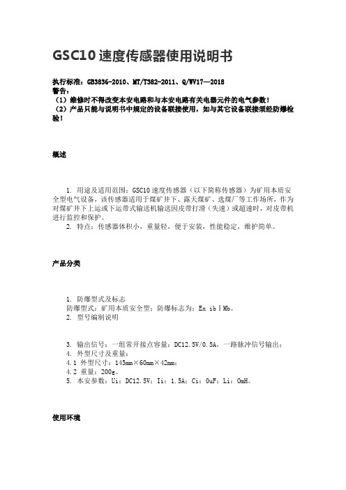
GSC10速度传感器使用说明书执行标准:GB3836-2010、MT/T382-2011、Q/WV17—2018警告:(1)维修时不得改变本安电路和与本安电路有关电器元件的电气参数!(2)产品只能与说明书中规定的设备联接使用,如与其它设备联接须经防爆检验!概述1. 用途及适用范围:GSC10速度传感器(以下简称传感器)为矿用本质安全型电气设备,该传感器适用于煤矿井下、露天煤矿、选煤厂等工作场所,作为对煤矿井下上运或下运带式输送机输送因皮带打滑(失速)或超速时,对皮带机进行监控和保护。
2. 特点:传感器体积小,重量轻,便于安装,性能稳定,维护简单。
产品分类1. 防爆型式及标志防爆型式:矿用本质安全型;防爆标志为:Ex ibⅠMb。
2. 型号编制说明3. 输出信号:一组常开接点容量:DC12.5V/0.5A,一路脉冲信号输出;4. 外型尺寸及重量:4.1 外型尺寸:145mm×60mm×42mm;4.2 重量:200g。
5. 本安参数:Ui:DC12.5V;Ii:1.5A;Ci:0uF;Li:OmH。
使用环境1.传感器在下列环境条件下应能正常工作a)环境温度:0℃~+40℃;b)相对湿度:不大于96%(+25℃);c)大气压力:80kPa~106kPa;d)煤矿井下有爆炸性混合物,但无破坏绝缘的腐蚀性气体的场合。
2.传感器能承受的最恶劣和安装贮运条件为:a)高温:+60℃;b)低温:-40℃;c)振动:加速度50m/s²;d)冲击:峰值加速度500m/s²。
结构特征及工作原理1. 结构特征:传感器由外壳、磁钢、接线端子等部分组成。
2. 工作原理:磁钢以一定的转速划过检测面,按动标定按钮,此时为正常转速,当所测转速显示值在10s内均为50%~70%之间或≤50%或≥110%时,关联控制箱应立即动作语音报警。
主要性能5.1 主要性能5.1.1 测速范围:0~10m/s;5.1.2 基本误差、线性度误差:±2.5%;5.1.3 重复性误差不超过基本误差限绝对值2/3。
矿用速度传感器说明书
矿用速度传感器说明书矿用速度传感器是一种用于测量和监测矿山设备运行速度的装置。
它在矿山行业中起着重要的作用,能够帮助矿山企业提高运输效率、降低能耗和维护成本。
本说明书将介绍矿用速度传感器的工作原理、安装方法和注意事项。
1. 工作原理:矿用速度传感器是基于速度脉冲计量原理工作的。
它通常由一个传感器和一个显示装置组成。
传感器通过检测矿用设备上的齿轮、皮带或链条等传动部件的旋转运动来测量其速度,并将信号传输给显示装置。
显示装置可以实时显示设备的运行速度,帮助矿山操作人员监测设备的工作状态。
2. 安装方法:矿用速度传感器的安装方法因设备类型和传感器型号而异。
一般来说,传感器应安装在设备上的旋转部件上,并保持与传动轴的平行位置。
安装时需确保传感器与设备的配合良好,避免发生误差。
此外,传感器的连接线应与设备的电源线路相隔一定距离,以避免干扰。
3. 注意事项:- 检查传感器是否与显示装置匹配。
矿用速度传感器有不同的工作范围和输出信号类型,所以在购买和安装前,需要确保传感器与显示装置兼容。
- 定期检查传感器的工作状态。
定期检查传感器的连接线是否完好,传感器是否存在损坏或异物堵塞的情况,以确保传感器的正常工作。
- 避免传感器过热。
由于矿山环境条件复杂,传感器容易暴露在高温环境中。
因此,需要采取相应的措施,如安装散热器或使用耐高温的材料,以防止传感器过热引起故障。
- 定期校准传感器。
随着时间的推移,传感器的精确度可能会发生变化。
因此,建议定期校准传感器,以保证测量结果的准确性。
总结:矿用速度传感器是一种可靠的设备,能够帮助矿山企业实时监测和控制设备运行速度。
本说明书介绍了矿用速度传感器的工作原理、安装方法和注意事项。
使用矿用速度传感器可以帮助矿山企业提高生产效率和安全性,降低能耗和维护成本。
OES非接触光电速度传感器

OES-Ⅱ非接触式光电速度传感器使用说明书一、基本原理、优点及使用范围在道路现场进行高精度测量汽车速度,行驶距离和对汽车进行加速、制动和滑行考核,历来均采用五轮仪。
五轮仪较为坚固,操作方便,价格适中,在低中速范围能较好满足测试需要,但当速度高于100公里/小时时,路面稍许不平会引起轮盘跳动打滑,从而带来测量误差。
而且五轮仪重量较重,特别对小型汽车成为一负载,限制了车速,因此五轮仪不能满足小型车辆高速段的测试要求。
OES-II型非接触式光电传感器采用特殊的大面积硅光电器件作探测器。
使用时将仪器安装在汽车外侧,镜头对准用灯光照明的地面。
汽车行驶时,地面的杂乱花纹经光学系统成像,并扫描过硅光电器件,经过光电转换和空间滤波后,传感器仅输出一随机窄带正弦波信号,信号的频率与车行速度成正比。
将传感器输出的信号经TRF型带通跟踪滤波器滤波和整形后,转换为标准TTL脉冲输出,每一脉冲严格对应汽车相对地面走过的一段距离。
将输出信号经过计数和微机处理后就可实时显示车行速度、路程、加速度和经过时间,并可将数据进行存储和打印。
OES-II光电传感器和TRF型跟踪滤波器在测量精度上比五轮仪高出了一个数量级,在灵敏度、测量范围等性能上超过国外同类产品。
传感器对不同类型的道路灵敏度相同(日本产品需手动调节放大器增益),在晴天阳光直射(无阴影)的现场可不开灯进行高精度测量,其光学系统设计独特,汽车上下颠簸不影响测量精度。
仪器响应极快,可有效测量汽车加速度和制动过程(日本产品不能有效测量>0.6g的急速变化过程),同时设有白线信号输出,用户在现场可方便进行高精度自校。
OES-II光电传感器和TRF型跟踪滤波器可靠性极强,特别适用于汽车、拖拉机和摩托车外场路面行驶性能的高精度测试,由于其采用非接触原理测量,还适用于火车、钢板、编织布等运动目标的高精度测速测长。
该产品荣获91年中国汽车工业科技进步二等奖和92年国家科技进步三等奖。
二、 OES-Ⅱ光电传感器技术指标●输出波形:正弦波(>0.1Vp-p)●测速范围: 0.5~250公里/小时●对应频率: 35HZ~17.5KHZ●周期当量: 4mm/1周期或10mm/1周期●照明灯功率: DC12V、55w●光学视场: 50mm×60mm●工作距离:照明灯距地面约600mm探测头前端距地面约500mm●高差影响:工作距离在500±100mm内,测量误差2%●其他功能:有白线信号输出●尺寸重量: 86mm×94mm×260mm,重2.5公斤三、使用说明1、传感器安装使用方法OES-II光电传感器在灯座侧面有四个M8安装螺孔,使用时将传感器用螺栓安装到真空吸盘支架上,吸盘吸附于汽车前端或后端车体上,并且要防止汽车开行时传感器有较大幅度的抖动,或汽车制动时产生变形、移位或甩动,否则混入附加信号影响测量精度,用吸盘支架安装时,不要忘记用保险绳缚牢,防止吸盘松脱产生意外。
杰诺速度传感器说明书

3、齿形:渐开线或梯形直齿4、齿轮材料:导磁材料◆接线图:◆选型表齿轮传感器型号CL12-3005NACL12-3005PA输出方式NPNPNP外形直径12mm 额定感应距离(SN)5mm 检测频率1Hz┈10KHz检速范围1┈20000(转/分钟)(与合适齿轮配套)工作电压6...24VDC 防护等级IP67最大输出电流200mA 运行温度―25℃―+75℃保护措施有工作电压极性保护和输出短路保护注:如遇到传感器不感应时,可调近距离或手工测试下传感器最灵敏区域,安装时使齿轮经过此区域。
因传感器内部有永磁体,安装时应避免齿轮与传感器头之间因吸引而产生撞击。
◆概述:本传感器采用电磁感应原理来达到测速目的,具有输出信号大,不需要放大,抗干扰性能好,可在烟雾、油气、水汽等恶劣环境中使用等特点,可替代其他相关齿轮传感器,广泛用于国防化工,纺织机械领域。
◆产品特点:1.输出稳定方波、抗抖动能力强适用于各种场所的速度检测。
2.全密封设计,防水防油防尘;其优点是温度范围宽,热稳定性高,抗干扰能力强。
◆产品安装:1.安装时用传感器自带的螺母固定在安装孔上,固定装置建议采用非导磁材料(铜、不锈钢等),传感器应正对齿面安装,齿面和传感器前端面的间距不应大于额定检测距离。
2.检测距离与配套使用的检测齿轮的模数相关,模数越大可以有效检测的距离越长。
◆注意事项(1)传感器输出线中的金属屏蔽层应接大地另线。
(2)不允许在温度为250℃以上强磁场环境中使用及放置。
(3)安装及运输过程中应避免强烈撞击。
(4)在被测轴跳动较大时,应注意适当放大间隙,避免损坏。
◆检测齿轮1、模数:m≥12、齿轮厚度:≥4mm。
GS4(A)型速度传感器(使用说明书)

GS4(A)型速度传感器执行标准:Q/HWT58-2005 使用说明书淮南市万泰电子有限责任公司二00五年八月GS4(A)型速度传感器使用说明书1用途及适用范围GS4(A)型速度传感器(以下简称传感器)适用于煤矿井下含有爆炸性气体(CH4)的环境中以及露天煤矿、选煤厂等工作场所,作为矿用带式输送机保护装置的速度保护信号检测之用。
2主要技术特征2.1 防爆型式:矿用本质安全型,防爆标志:ExibI;2.2 型号含义G S 4 (A)设计序号主参数,测量范围(m/s)速度传感器2.3 本安工作电压:DC12V;2.4 本安工作电流:≤10mA;2.5 测量范围:设定额定线速度Ve为1.5m/s、2.5m/s和3.5m/s三个档位;2.6 动作性能:当测量速度连续10s均在(50%~70%)Ve范围内,或测量速度≤50%Ve以及测量速度≥110%Ve时,传感器输出低电平,其余时传感器输出高电平;2.7 输出信号:电平信号,高电平≥11V±1V(拉出2mA电流时),低电平≤0.5V;2.8 关联设备:ZJZ-SZ(A)矿用带式输送机保护装置主机,淮南市万泰电子有限责任公司生产;防爆合格证号:1042726;安全标志合格证号:20046081。
2.9 传输电缆长度<1000m,分布电容<0.1μf/Km,分布电感<1mH/Km;2.10 外形尺寸:150mm×70mm×320mm;2.11 质量:2Kg。
3 环境条件3.1 正常工作条件3.1.1 周围环境温度为-5℃~40℃;3.1.2 海拔高度不超过2000m(气压80KPa~110KPa);3.1.3 周围空气相对湿度≤98%(25℃);3.1.4 含有甲烷等爆炸性气体的矿井中;3.1.5 无显著摇动和冲击振动的地方;3.1.6 无破坏绝缘的气体或蒸气的环境中;3.1.7 能防滴水的地方。
3.2 最恶劣贮运条件高温:60℃;低温:-40℃;平均相对湿度:95%(25℃)。
98893送电式加速度传感器说明书
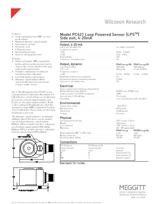
98893 Rev.B 01/10Output, 4-20 mA Full scale, 20 mA (±5%) ............................................................. see Table 1 on back Frequency response:±10% ....................................................................................... 10 Hz - 1.0 kHz ±3 dB ....................................................................................... 4 Hz - 2 kHz Repeatability .............................................................................. ±2%Transverse sensitivity, max ....................................................... 5%Output, dynamic PC421xxx-yy-DA PC421xxx-yy-DV Sensitivity (±10%) ....................................................................... 100 mV/g 100 mV/ ips Full scale .................................................................................... 20g, peak 1.5 ips @ 1kHz Frequency response:±3 dB ....................................................................................... 2.5 Hz - 10 kHz 2.5 Hz - 2.5 kHz Amplitude nonlinearity, maximum ............................................ 1%Resonant frequency, mounted, nominal ................................... 21 kHz Transverse sensitivity, max ....................................................... 5%Electrical Power requirements (Two wire loop power):Voltage (between pins A & B) .................................................... 10 VDC min, 30 VDC max Loop resistance 1 at 24 VDC, maximum ..................................... 700ΩTurn on time, 4-20 mA loop ....................................................... 30 seconds Grounding................................................................................... case isolated, internally shielded Environmental Temperature range .................................................................... –40 to 85°C Vibration limit ........................................................................... 250 g peak Shock limit ................................................................................ 2,500 g peak Sealing ...................................................... ................................ hermetic PhysicalSensing element design ............................................................ PZT ceramic / shear Weight ....................................................................................... 320 grams Case material ............................................................................. 316L stainless steel Mounting .................................................................................... 1/4 - 28 captive bolt PC421xxx-yy PC425xxx-yy-Dz Outut connector , MIL-C-5015 style ........................................... 2 pin 3 pin Mating connector ....................................................................... R6 type R6G type Recommended cabling .............................................................. J9T2A J9T3AConnectionsFeatures • Peak equivalent, true RMS or true peak output • Optional dynamic signal output • C orrosion resistant • Hermetic seal • ESD protection • Overload protection • Reverse wiring protectionModel PC421 Loop Powered Sensor (LPS TM )Side exit, 4-20mA The 4-20 mA output of the PC421 Series is proportional to vibration. An output of 4 mA indicates a level of 0 ips or no vibration present for velocity output models and 0 g for acceleration output models. A full-scale reading of 20 mA indicates that the maximum range (RMS, Equivalent Peak or True Peak) of the chosen unit, acceleration of velocity, is present.The dynamic signal output is an optional addition. Any of the base sensor models can also have dynamic signal output. Adding -DA to a model specifies a dynamic acceleration signal output (100 mV/g). Adding -DV to a model specifies a dynamic velocity signal output (100 mV/ips). Benefits • Choice of output: RMS, equivalent peak, and true peak; permits you to choose the sensor that best fits your industrial requirements • Provides continuous trending of overall machine vibration • Can help guide maintenance • Dynamic signal output allows spectral vibration measurements using a single sensorSee back for notes.Due to continued research and product development, Wilcoxon Research reserves the right to amend this specification without notice.P C 421xxx-yy P C 421xxx-yy-Dz Connector pin Connector pin Function shell shell ground A A loop positive (+)B B loop negative (-)NA C dynamic signalxxx (4-20 mA output type) -yy (full scale) -Dz (dynamic output)AAR = acceleration, RMS -05 = 5 g (49 m/sec2) -DA = dynamic acceleration 100 mV/gAP = acceleration, equivalent peak B -10 = 10 g (98 m/sec2) (10.2 mV/ m/sec2)ATP = acceleration, true peak C -20 = 20 g (196 m/sec2) -DV = dynamic velocity 100 mV/ips (3.94 mV/ mm/sec)VR = velocity, RMS -05 = 0.5 i.p.s. (12.8 mm/sec) -DA = dynamic acceleration 100 mV/g VP = velocity, equivalent peak B -10 = 1.0 i.p.s. (25.4 mm/sec) (10.2 mV/ m/sec2)VTP = velocity, true peak C -20 = 2.0 i.p.s. (50.8 mm/sec) -DV = dynamic velocity 100 mV/ips -30 = 3.0 i.p.s. (76.2 mm/sec) (3.94 mV/ mm/sec) -50 = 5.0 i.p.s. (127 mm/sec)Table 1: PC421xxx-yy-Dz Model Number SelectionA Dynamic output is an option on all models. If dynamic output option is not desired, do not add -DA or -DV to the model number.BEquivalent peak output is developed based on the true RMS value of vibration. For a pure sine wave, the equivalent peak output is 1.414 times the RMS value.C True peak output is based on the actual measured peak value using the time waveform and is not based on the RMS calculation.Notes: 1 maximum loop resistance (RL) can be calculated by:V DC power - 10 V RL (max. resistance) = 20 mA2 Lower resistance is allowed, greater than 10Ω recommended3 Minimum R L wattage determined by: (0.0004 x R L )All wire and cable used for installation of the PC421-series sensor should be shielded. Gener-ally accepted instrumentation wiring practice considers the best way to ground the shield is to connect it at the measurement end of the cable. The shield should not be wired to ground at the sensor end of the cable. Wilcoxon R6W, R6GQAI, R6GQI and R6QI type connectors all leave the shield unconnected at the sensor end of the cable.Wilcoxon Research Inc20511 Seneca Meadows ParkwayGermantown, MD 20876USATel: 301 330 8811Fax: 301 330 8873Email:********************。
3B SCIENTIFIC 物理学实验室 5-g 加速度传感器 用户手册说明书

3B SCIENTIFIC ®PHYSICS1Beschleunigungssensor 5-g U11363Bedienungsanleitung07/07 Hh1. Sicherheitshinweise•Um dauerhafte Beschädigungen des in der kleinen schwarzen Box eingebauten Halbleiter-sensors zu vermeiden, die maximale Achsen-unabhängige Beschleunigung vom 1500-fachen der Erdbeschleunigung nicht überschreiten! • Das Sensorelement aus keiner größeren Höheals maximal 1,2 m auf einen harten Unter-grund fallen lassen!• Der Beschleunigungssensor 5-g nur für Ausbil-dungszwecke einsetzen!Der Beschleunigungssensor 5-g ist nicht für Si-cherheits-relevate Anwendungen geeignet!2. BeschreibungSensorbox mit fest angeschlossenem Z-Achsen-empfindlichen Halbleiter-Beschleunigungsaufneh-mer zur Messung von Erdbeschleunigung und Be-schleunigungen von K örpern im Allgemeinen bis ±5-g.Wirkungsrichtung …Earth’s Gravity Field“ (Z-Achse) auf dem Beschleunigungsaufnehmer aufgedruckt. …K apazitives“ Messverfahren (g-cell) mit eingebau-ter linearisierender Signalaufbereitung, Tiefpassfil-terung, Temperaturkompensation und automati-schem Selbsttest.Die Sensorbox besitzt eine automatische Erkennung durch das Interface!3. Lieferumfang1 Sensorbox mit fest angeschlossenem Beschleu-nigungsaufnehmer mit einer K abellänge von2 m1 K lettbandzuschnitt 500 mm lang, 20 mm breit, selbstklebend1 miniDIN-Anschlusskabel 8-pin, 60 cm lang 1 Bedienungsanleitung für U113633B Scientific GmbH • Rudorffweg 8 • 21031 Hamburg • Deutschland • Technische Änderungen vorbehalten© Copyright 2007 3B Scientific GmbH4. Technische DatenMessbereich: 0 bis ±50 m/s² Sensortyp: K apazitiver Halbleiter-sensor Empfindlichkeit: typisch 400 mV/g Nichtlinearität: max. ±1 % vom gesam-ten Messbereich Auflösung: 0,03 m/s² Bandbreite: typisch 50 Hz Befestigungsbohrung des Aufnehmers: max. 3 mm Ø5. Bedienung•Die Sensorbox in der Nähe des Experimentes platzieren und den Beschleunigungsaufnehmer (kleine schwarze Box) am zu untersuchenden Körper (Target) befestigen; hierzu das mitgelie-ferte K lettband oder eine Schraubbefestigung wählen.•Im Display des 3B NET log TM den Wert der Be-schleunigung ablesen.6. AnwendungenRollen- und Luftkissenfahrbahnversuche: Beschleunigte Abwärtsbewegung Elastischer und unelastischer Stoß Schwingendes Feder-Masse-SystemHochauflösende Messung einer Objektneigung Schwingendes PendelSprungversuche; …Bungee Jumping“7. VersuchsbeispielMessung der Beschleunigung in einem gedämpft-schwingenden Feder-Masse-SystemBenötigte Geräte: 1 3B NET log TMU113001 3B NET lab TMU11310 1 Beschleunigungssensor 5-g U11363 1 Stativfuß U13270 1 Stativstange, 750 mm lang U15003 1 Stativstange, 250 mm lang U15001 2 Universalmuffen U13255 1 Schraubenfeder 3 N/m U15027 1 Wägestück 100 g, aus U30016 • Versuchsaufbau gemäß Fig. 1.• 3B NET lab TM-Anwendung (Template) zum Expe-riment mit dem Beschleunigungssensor 5-göffnen. • Beschleunigungsaufnehmer mit einem K lett-bandflecken am Wägestück befestigen.•Wägestück und Beschleunigungsaufnehmer in das untere Schraubenfederauge einhängen und darauf achten, dass der Schwingungsvor-gang im Bewegungsablauf nicht behindert wird.•Anschlusskabel des Beschleunigungsaufneh-mers wie in Fig. 1 gezeigt über die Universal-muffe legen. Hieraus ergibt sich ein zusätzli-ches Dämpfungsdekrement.• Wägestück händisch bis zum Niveau des Stativ-fußes ziehen und loslassen.• In 3B NET lab TM die Messkurvenaufnahme star-ten (Fig. 2).•Messkurve auswerten.Fig. 1 Messung der Beschleunigung in einem gedämpft-schwingenden Feder-Masse-SystemFig. 2 Bildschirmdarstellung einer gedämpften Feder-Masse-Schwingung in 3B NET lab TM(U11310)。
速度传感器SA(SC)使用说明书

****************速度设定见最后一页*******************速度传感器SA(SC)型使用说明书版本号:NO1出版日期:2006/11/2天津华宁电子有限公司分公司目录1. 概述2. 结构特征3. 电气性能4. 工作原理5. 安装及使用6. 外形尺寸及重量7. 维护和保养8. 包装、运输和贮存附表一:额定速度设定表为了保证安全并获得最佳效能,安装使用产品前,请详细阅读使用说明书并妥善保管,以备今后参考。
1.概述·此传感器为测速传感器。
皮带额定速度由面板上的6组合拨动开关设定,额定带速设定范围从每秒0.9米到每秒6米,每0.1米为一档,共计52档。
额定速度设定地址见表1。
·输入脉冲0-96HZ,输出频率200-1000HZ。
输出频率与设定的额定皮带速度无关,输出频率仅与输入脉冲数有关。
·具有欠速和超速保护功能2.结构特征此模块输入输出全部隔离,内置高性能单片机。
图2-1 整体外形图2-1 内部顶视图1)共有六个接线端子它们是:VIN 12V到18V电源正GND 12V到18V电源负KA 接点输出,速度保护时常开,速度正常时常闭POUT+ 脉冲输出正端。
光偶三极管集电极,需要接外部电源正和上拉电阻POUT-脉冲输出负端。
光偶三极管发射极,需要接外部电源负2)面板上K1是速度选测开关,开关打向ON位置,表示电平1,开关打向OFF位置,表示电平0。
D0和D5的位置如图所示。
最右边是D0。
编码选择见表1。
3)LD2是保护指示灯,在速度保护时灯灭,速度正常时灯亮。
4)速度传感器探头红色:给速度传感器探头的电源正12-18V黑色:给速度传感器探头的电源地黄色:速度传感器探头的信号3.电器特性输入电压 +12V- +18V输出量一路继电器开关量;一路频率量(200-1000HZ)继电器载流≦400mA通信接口无正常工作功率≦0.6W主体工作环境温度 -10 - 65摄氏度湿度 8-80% RHG,相对凝固状态(无冷凝)4.工作原理速度传感器对设定的额定皮带速度的50%,70%,110%的速度段进行检测,判断是否欠速,超速。
杰诺XSAV11801速度传感器说明书

杰诺速度传感器
用途和适用范围
这些自含的转速监控传感器或称速度开关具有一体化的特征:在同一个外壳中,有脉冲检测、处理器和输出转换放大器,这些都是一个集成式转速检测装置所必须的。
这个装置为打滑检测、传送带损坏、传动轴切变与过载等问题提供了解决方案。
它应用于以下机器中:传送带、链式升降机、阿基米德式螺杆、研磨机、粉碎机、水泵、离心式甩干机、混合器等。
我公司生产的速度监测开关采用优质原件,先进设备生产,达到国产领先水平,我产品已被海螺水泥、徐工机械、白洋合水泥等大型工矿企业选择使用。
工作原理
这类接近传感器的输出信号是集成在传感器内的脉冲比较器处理的,由待监控部件产生的脉冲频率与传感器中的预置频率进行比较,当被测物体的频率小于速度开关设定频率时开关为打开状态;当被测物体的振动频率大于速度开关设定频率时开关为闭合状态。
我公司生产的转速监控传感器尤其适用于欠速的监控,当移动部件转速低于预设的临界值时,传感器的输出电路就关断。
注:通常传感器在通电后延迟9秒启动,以允许被监控对象有一个启动过程。
开关频率调整
首先用螺丝刀旋转拧开尾部直径8毫米的黑色旋钮,拿掉旋钮后,即可看到里面的电位计
调整传感器临界频率:使用电位计,大约15圈
增加传感器临界频率:顺时针旋转调节螺丝
减少传感器临界频率:逆时针旋转调节螺丝
电位计调整曲线:.
低速型高速型
开关最小安装距离(mm)与接线图
e≥20e≥120e≥30d≥30h≥0
接线图。
polar速度传感器用户手册说明书

用户手册目录2简介3开始4速度传感器零件4安装速度传感器4配对5重要事项6保养和维护6电池6常见问题解答6技术规格6Polar速度传感器设计用于在骑车时测量速度和距离。
传感器与Bluetooth®Smart Ready装置兼容,后者支援Bluetooth®骑车速度服务。
利用Bluetooth®Smart,您可以将传感器与许多领先的健身应用程式以及Polar产品结合使用。
登录/support了解兼容的产品。
本用户手册的最新版本可从以下网址下载:/support。
速度传感器零件1.速度传感器(图1A和图2A)2.辐条感应磁铁(图2B)图1图2安装速度传感器若要安装速度传感器和辐条磁铁,则需小刀和十字头螺丝刀。
1.建议将速度传感器安装在您的自行车的前叉上(如图1A)。
2.将橡胶零件连接至速度传感器(图3)。
图33.使扎带从速度传感器和橡胶零件上通过(图2A)。
向前叉调整传感器,以使POLAR标志向外。
宽松地调整扎带。
此时不要将其完全系紧。
4.将磁铁连接至辐条,与速度传感器等高(图2)。
传感器背面上有一个小孔(图3A),绕过传感器时磁铁应指向该孔。
将磁铁固定在辐条上,用螺丝刀将其拧紧。
此时不要将其完全拧紧。
5.微调磁铁和速度传感器的位置,使磁铁接近传感器,但不要接触(图2)。
尽量将传感器移近车轮/辐条。
传感器与磁铁之间的间隙不得超过4毫米/0.16英寸。
磁铁与传感器之间的间隙应刚好可容纳一条扎带。
6.转动前胎,以测试速度传感器。
如果传感器上的红灯闪烁,则表明磁铁和传感器定位正确。
如果您保持轮胎旋转,灯将停止闪烁。
用螺丝刀将螺丝拧紧至磁铁。
另外系紧扎带,切除多余的扎带末端。
在您开始骑车之前,在接收装置或手机应用程式中设置您的自行车车轮大小。
配对新的传感器只有与接收装置配对后才能接收数据。
如需了解更多信息,请查阅接收装置或手机应用程式的用户指南。
为确保传感器与接收装置之间的良好连接,推荐您将设备保持在车把上的自行车固定装置上。
Honeywell 速度传感器产品范围指南说明书

Speed Sensors Product Range GuideWith more than 50,000 products ranging from snap-action, limit, toggle, and pressure switches to position, speed, pressure, and airflow sensors, Honeywell has one of the broadest sensing and switching portfolios.Honeywell sensor, switch, and control components are tailored to exact specifications for stronger performance, longer productivity, and increased safety. Enhanced accuracy and durability are built into every part, improving output and endurance. For our customers, this can reduce expenditures and operational costs. Our global footprint and channels help to competitively price such components for your chosen application and provide immediate technical support.While Honeywell’s switch and sensor solutions are suitable for a wide array of basic and complex applications, our custom-engineered solutions offer enhanced precision, repeatability, and ruggedness. We offer domain knowledge and technology resources, along with a close working relationship, to develop and deliver cost-effective, individually tailored solutions. Whether clean-slate development or simple modifications to an existing design are needed, our expertly engineered solutions help to meet the most stringent requirements with world-class product designs, technology integration, and customer-specific manufacturing.Global service, sourcing, and manufacturing. Industry-leading engineers. Value-added assemblies and solutions. A one-stop, full-service, globally competitive supplier.For innovation that’s well apart, there’s only HoneywellTable of ContentsMagnetoresistive Sensor ICs . . . . . . . . . . . . . . . . . . . . . . . . . . . . . . . . . . . . . . .3Hall-effect Digital Sensor ICs . . . . . . . . . . . . . . . . . . . . . . . . . . . . . . . . . . . .4-5Hall-effect Digital and Linear Sensor ICs . . . . . . . . . . . . . . . . . . . . . . . . . . .6Value Added Magnetic Sensors . . . . . . . . . . . . . . . . . . . . . . . . . . . . . . . . . .7-8Active Speed Sensors . . . . . . . . . . . . . . . . . . . . . . . . . . . . . . . . . . . . . . . . . .9-10Passive Speed Sensors . . . . . . . . . . . . . . . . . . . . . . . . . . . . . . . . . . . . . . . . . . . .113NanopowerSeriesStandardPowerSeries2SS52MSeriesVF401APS00BDescription omnipolar MRsensor IComnipolar MRsensor IComnipolar MRdigital sensor IC2-wire MRfine pitch ringmagnet sensor IChigh resolutionmagneticdisplacementMagnetic Sensors |Magnetoresistive Sensor ICs1Dimensions:• SOT-23: 2,8 mm x 2,9 mm [0.11 in x 0.11 in]• Flat TO-92-style: 3,0 mm x 4,0 mm [0.12 in x 0.16 in] (not including leads)• VF-401 flat TO-92-style: 3,0 mm x 4,06 mm [0.12 in x 0.16 in] (not including leads)• SOT-89B: 4,2 mm x 4,5 mm [0.16 in x 0.18 in]• U-Pack: 4,5 mm x 4,5 mm [0.18 in x 0.18 in] (not including leads)• SOIC-8: 4,9 mm x 6,0 mm [0.19 in x 0.24 in]SL353SS30AT,SS40A,SS50ATSS311PT,SS411PSS340RT,SS440RSeriesDescriptionmicropower omnipolarHall-effect digitalsensor IClow-cost bipolarHall-effect digitalsensor IClow-cost bipolarHall-effect digital sensorIC with built-in pull-uplow-cost unipolarHall-effect digitalsensor ICFeaturescombined with very lowaverage current reducespower consumptionspeed capability, reversepolarity protectionlow voltage, enhancedsensitivityNorth pole (SS340RT)or South pole (SS440R),multiple magneticsensitivities (high,medium, and low) Magnetic Sensors |Hall-effect Digital Sensor ICs1Dimensions:• SOT-23: 2,8 mm x 2,9 mm [0.11 in x 0.11 in]• Flat TO-92-style: 3,0 mm x 4,0 mm [0.12 in x 0.16 in] (not including leads)• SOT-89B: 4,2 mm x 4,5 mm [0.16 in x 0.18 in]5SS345PT, SS445PSS351AT, SS451A, SS551ATSS360NT , SS360ST , SS360ST-10K, SS460S, SS460S-T2 VF360NT , VF360ST , VF460SSS360PT, SS460P, SS460P-T2unipolar Hall-effect digital sensor IC with built-in pull-up resistor low-cost omnipolarHall-effect digital sensor IC high sensitivity, latching Hall-effect digital sensor IC high sensitivity, latching Hall-effect digital sensor IC high sensitivity latching digital Hall-effect sensor IC with built-in pull-up resistor pole (SS345PT) or a South pole (SS445P)protection, typical operating point of 85 G at 25°C [77°F]no chopper stabilizationstandard for potential use in automotive applications, fastest response time in its class class, no chopper stabilization, operates from only 30 Gausstypical, at 25°C [77°F]Magnetic Sensors |Hall-effect Digital and Linear Sensor ICsDigitalVF526DTLinearSS490 SeriesSS39ET, SS49E, SS49E-F, SS49E-L, SS49E-T2, SS49E-T3, SS59ET1Dimensions:• 4-Pin SIP: 3,6 mm x 5,1 mm [0.14 in x 0.20 in]• SOT-89B: 4,2 mm x 4,5 mm [0.16 in x 0.18 in]• Flat TO-92-style:3,0 mm x 4,0 mm [0.12 in x 0.16 in] (not including leads)7Series103SR (digital)103SR (linear)Magnetic Sensors | Value AddedSeries SR16/SR17SR3SR4Description low-cost Hall-effect vane sensor Hall-effect digital position sensor magnetoresistive digitalMagnetic Sensors |Value Added9Series SNG-Q SNDH-T SNDH-HDescription quadrature speed and direction quadrature speed and direction single Hall-effect speed sensorFeaturesplatform-based approachenables cost-competitivenessand mechanical and electricalconfigurability; designed forpotential applications whereenhanced accuracy is required todetect small target featuresoffset self calibration, short circuitand reverse voltage protection,low jitter output, near zero speedavailable, zero speed sensingversions available, range of con-nector options Speed Sensors |ActiveSpeed Sensors |ActiveSeries584XXFeaturesproduces constant amplitude output signals suitable for direct use in many digital andlogic control applications, internal digital signal conditioningSeriesLCZZH10Featuresomni-directional sensor to target, low power consumption, zero speed, digital outputomni-directional sensor to target, low powerconsumption, zero speed, digital output11SeriesVRS General PurposeVRS Hazardous LocationVRS High OutputDescription/potential applicationsused where medium to high speeds or in electrically noisy environments with relatively small air gaps existused where explosion-proof or intrinsically safe sensors are requiredused where higher output voltages are needed, perform best at low to mediumspeeds with medium to high impedance loads (sealed front-end versions for use where the sensor is exposed to fluids, lubricants or adverseSeriesVRS High ResolutionVRS High TemperatureVRS Power OutputDescription/potential applicationsused where precise timing pulse is required, and/or fine pitch gears are usedused where the sensor is exposed to temperatures up to 260ºC [450ºF] (sealed front-end versions for use where the sensor is exposed to fluids, lubricants or adverse used where driving lowresistance loads at large air gaps is required, and larger actuators are usedSpeed Sensors |PassiveWarranty/RemedyHoneywell warrants goods of its manufacture as being free of defective materials and faulty workmanship during the applicable warranty period . Honeywell’s standard product warranty applies unless agreed to otherwise by Honeywell in writing; please refer to your order acknowledgement or consult your local sales office for specific warranty details . If warranted goods are returned to Honeywell during the period of coverage, Honeywell will repair or replace, at its option, without charge those items that Honeywell, in its sole discretion, finds defective . The foregoing is buyer’s sole remedy and is in lieu of all other warranties, expressed or implied, including those of merchantability and fitness for a particular purpose. In no event shall Honeywell be liable for consequential, special, or indirect damages.While Honeywell may provide application assistance personally, through our literature and the Honeywell web site, it is buyer’s sole responsibility to determine the suitability of the product in the application .Specifications may change without notice . The information we supply is believed to be accurate and reliable as of this writing . However, Honeywell assumes no responsibility for its use .005911-11-EN IL50 GLO Printed in USA May 2017© 2017 Honeywell International Inc . All rights reserved .Find out moreTo learn more about Honeywell’s sens-ing and switching products, call +1-815-235-6847, email inquiries to *********************, or visit Honeywell Sensing and Internet of Things 9680 Old Bailes Road Fort Mill, SC 29707 honeywell .com。
绝对角速度传感器 ECI 1319, EQI 1331, EBI 1335说明书

09/2018Product InformationECI 1319EQI 1331EBI 1335Absolute Rotary Encoders without Integral Bearing Suited for safety-related applications up to SIL 3 when coupled with additional measuresProduct Information ECN 1319, EQI 1331, EBI 1335 09/20182ECI 1319, EQI 1331, EBI 1335Rotary encoders for absolute position values with safe singleturn information • Rugged inductive scanning principle• Mounting-compatible to photoelectric rotary encoders with 07B stator coupling • 0Y A mounting flange• Blind hollow shaft for axial clamping Ø 12.7 mm (44C) or Ø 12 mm (44A)ECI/EQI/EBI: Dynamic motion permitted over entire range. ECN/EQN: No dynamic motion permitted 10 = M10 back-off thread11 = Direction of shaft rotation for ascending position valuesProduct Information ECN 1319, EQI 1331, EBI 1335 09/201832)F urther tolerances may occur in subsequent electronics after position value comparison (contact manufacturer of subsequent electronics)3)See General electrical information in the Interfaces of HEIDENHAIN Encoders brochure or at www.heidenhain.de 4)At T = 25 °C; U Bat = 3.6 VProduct Information ECN 1319, EQI 1331, EBI 1335 09/201841)10 Hz to 55 Hz constant over distance 4.9 mm peak to peakProduct Information ECN 1319, EQI 1331, EBI 1335 09/20185The blind hollow shaft of the rotary encoder is slid onto the measured shaft and fas-tened with a central screw. The stator is mounted by a centering diameter with three mounting screws. In each case, use screws with materially bonding anti-rotation lock (see Mounting accessories).The following material properties and conditions must be complied with when customers plan and execute installation.MountingProduct Information ECN 1319, EQI 1331, EBI 1335 09/20186Mounting accessoriesScrewsScrews (central screw, mounting screws) are not included in delivery.They can be ordered separately.Please note the information on screws from HEIDENHAIN in the brochure titled En-coders for Servo Drives , chapter General mechanical information under Rotary encod-ers with functional safety.Mounting aidTo avoid damage to the cable, use the mounting aid to connect and disconnect the ca-ble assembly. The pulling force must be applied only to the connector of the cable as-sembly, and not to the wires.ID 1075573-01For further mounting information and mounting aids, refer to the mounting in-structions and the Encoders for Servo Drives brochure. The installation can be inspected with the PWM 21 and the ATS software (see document 1082415).Electrical connection• Provide bit error rate as per specification 533095!• CE compliance of the complete system must be documented!TE Connectivity Industrial GmbHSpeedTEC is a registered trademark ofP1)Connecting element must be suitable for the maximum clock frequency usedNote for safety-related applications:• Provide bit error rate as per specification 533095!• CE compliance of the complete system must be documented!Product Information ECN 1319, EQI 1331, EBI 1335 09/20187Product Information ECN 1319, EQI 1331, EBI 1335 09/20188the Encoders for Servo Drives brochure)Cable shield connected to housing; U P = Power supply voltageSensor: The sense line is connected in the encoder with the corresponding power line.Vacant pins or wires must not be used!Note for safety-related applications: Only completely assembled HEIDENHAIN cables are qualified. Do not modify cables or ex-change their connectors without first consulting with HEIDENHAIN Traunreut.SpeedTEC is a registered trademark of TE Connectivity Industrial GmbHElectrical connectionDR. JOHANNES HEIDENHAIN GmbH Dr.-Johannes-Heidenhain-Straße 583301 Traunreut, Germany {+49 8669 31-0|+49 8669 32-5061E-mail:******************www.heidenhain.dethe Encoders for Servo Drives brochure)2)Connected inside encoderCable shield connected to housing; U P = Power supply voltageSensor: The sense line is connected in the encoder with the corresponding power line.Vacant pins or wires must not be used!Note for safety-related applications: Only completely assembled HEIDENHAIN cables are qualified. Do not modify cables or ex-change their connectors without first consulting with HEIDENHAIN Traunreut.SpeedTEC is a registered trademark of TE Connectivity Industrial GmbH1000353 · 04 · A · 02 · 09/2018 · PDFThis Product Information document supersedes all previous editions, which thereby become invalid. The basis for ordering from HEIDENHAIN is always the Product Infor-mation document edition valid when the order is made.。
便携式加速度传感器灵敏度标定仪MC-20说明书
便携式加速度传感器灵敏度标定仪MC-20使用说明书长沙鹏翔电子科技有限公司富士陶瓷株式会社本使用说明书详细记载了MC-20的操作方法、技术参数、注意事项等内容,请在使用之前详细阅读。
产品清单确认请在收到产品的时候,首先确认产品和以下附件是否齐全。
如有缺失,请立即联系富士陶瓷株式会社中国总代理—长沙鹏翔电子科技有限公司。
名称数量备注MC-20主机1台-低噪声电缆1根LN-0300.5m Miniature-BNC转接头各1个M6-M3(约4.9g)M6-No.10-32UNF(约1.2g)M6-Flat(约5.0g)M6标准螺栓(约1.3g)手提箱1个-专用AC适配器1个型号:DCP01USB电缆1根型号:USB01PC通信软件光盘1张程序安装用CD-ROMBNC插座保护套1个套在主机插座上,保护BNC插座用本机使用说明书1本本手册数据传输软件说明书1本-长沙鹏翔电子科技有限公司目录1、概要2、各部件名称及功能说明3、菜单选项和设置内容4、使用方法电源的准备传感器的安装方法驱动测试5、功能说明6、技术参数7、外形尺寸1.概要加速度传感器简易标定仪MC-20可以对电荷输出型以及内置放大器型加速度传感器进行标定。
对被测加速度传感器施加振动,通过输出的信号来显示加速度传感器的灵敏度。
*关于标定*本产品通过单一频率(159.2Hz)对加速度传感器的灵敏度进行测量,达到对传感器性能的简易诊断目的。
长沙鹏翔电子科技有限公司2.各部件名称及功能说明本体上面1电源开关长沙鹏翔电子科技有限公司ON/OFF电源开关键2选项按键切换到测量电荷输出型传感器的模式。
测量完成时(Single mode)需长按约1秒进行再次测量。
显示菜单画面时,可以用来移动光标。
※有关Single mode的功能说明请参照13页。
3选项按键切换到测量内置放大器型传感器的模式。
测量完成时(Single mode)需长按约1秒进行再次测量。
显示菜单画面时,可以用来移动光标。
西门子 RBSS速度传感器 说明书

ø 127 mm (5")
6传0 动齿轮
102 mm (4")
114 mm
(4.5") ref. 105 mm (4.13")
102 mm (4")
7ML19985GX62
5 mm (0.19")
25 mm (1")
25 mm (1") 51 mm (2")
29 mm (1.13")
57 mm (2.25")
带有合适的 接近开关认证 ( Pepperl + Fuchs #NJ0.8-5GM-N )
• ATEX: II 2G, EEx ia IIC T6 (
IS开关隔离器)
• CSA/FM (带有合适的IS开关隔离器或开关放大器):
和 Class I, Div. 1, Groups A,B,C, D.
和 系统认证 Class II, Div. 1, Groups E, F, G
Page 2
RBSS速度传感器 – 使用指南
7ML19985GX62
尺寸图
RBSS
ø通2过5 m两m块(板1") 1电/2缆" N接P头T
102 mm (4")
51 mm (2")
32 mm (1.25")
610 mm (24")
3屏m蔽(电10缆ft)
648 mm (25.5")
传感器
注:RBSS IS的电缆为2 m, 2芯 26 AWG, PVC屏蔽。 可选安装托架
Milltronics®是西门子过程仪表的注册商标。
西上电传E-门海话真ma子浦::i((l:东(00s新中22c11.区国i))nf浦)33o88.东有c88n99大限@23道公s32i86e司114m号en船s.舶co大m厦 7 楼
CMCP575速度传感器操作手册说明书
OPERATION MANUAL CMCP575-XXX-XXXSpeed TransmitterREV. A 5-26-2009Model Description:The CMCP575 is a Frequency to DC Transmitter. The transmitter accepts a periodic waveform and computes ABSOLUTE FREQUENCY. The CMCP575 is factory set to provide a 4-20mA output proportional to this level within a specified range such as 0-5,000 RPM. The 4-20 mA output is suitable for direct connection to a Programmable Logic Controller (PLC) or Distributed Control System (DCS). Additionally, the CMCP575 mounts on standard DIN rail.The CMCP575 can easily be calibrated in the field with the use of a frequency generator. Additional outputs are provided to supply your control system with a wide variety of outputs such as 0-20mA, 0-10mA, 0-1mA, 1-5VDC, 0-5VDC, or 0-10VDC.Power:The CMCP575 requires externally supplied DC power. The chosen power supply should have a nominal output of +24Vdc and be capable of supplying a minimum of 30mA for eachCMCP575 in the system. A linear-regulated power-supply dedicated to the transmitter is recommended. It is also recommended that connections between the power supply and the transmitter be made with twisted-shielded instrument cable. The cable shield should float at the transmitter and connect to common at the power-supply, system common end only. Transducer:The CMCP575 is factory configured for use with the sensor requested. The specific type is identified under the “Input Type” on the side label. The most common type of sensors are the Eddy Probe and Hall Effect Sensor. Sensor requirements can be found on the specifications page of this manual. The wire used to connect the sensor to the transmitter should be an overall shielded cable. The shield must be grounded at the input negative of the CMCP575 and left floating at the sensor.Transducer Cable:It is strongly recommended that the transmitter be mounted as close as practical to the associated transducer. This will prevent signal distortion associated with current drive limitations, and will minimize interference from external electro-magnetic noise sources (EMI). A well shielded, properly installed transducer cable is absolutely necessary to obtain reliable operation. Twisted-shielded cables designed and pre-fitted with the proper transducer connector, and sold for this specific purpose are highly recommended. The cable shield should be open at the transducer end, and connected to the input negative on the transmitter only. The cable should be routed as far away from other electrical circuits as possible, and run in metal conduit where possibleCMCP575 OPERATION MANUAL PAGE 2Full Scale Range:The CMCP575 is supplied factory calibrated for the full-scale range specified at the time of order. Other ranges may be implemented by changing the calibration as needed. See the “Test and Calibration” section of this manual for more information. The factory calibrated range is listed on the side label as a dash number.4-20 mA Output:The primary output of the transmitter is the 4-20 mA current output which is proportional to the full scale range of the unit. IE: If the range is 0 – 5,000 RPM, then 4 mA indicates a reading of 0 RPM and 20 mA indicates a reading of 5,000 RPM. This output is intended to drive a maximum resistive load of 950 Ohms with respect to system common at the PLC/DCS input.Setup:The CMCP575 units are factory calibrated per order. Usually, a complete re-calibration is not required unless you want to change the input type, output type, or the range of the unit. A calibration sticker located on the side of the unit identifies the model, calibration and options present.Test/Calibration Instruments:The test equipment listed below is required to perform Zero and span calibrations:(1) +24 Vdc linear regulated power supply(1) 4.5 digit DC/True RMS reading digital volt/current meter. Fluke 87 or better(1) Sine wave signal generator with floating output.Configuration:Note: For re-calibration of the existing range proceed to the “Calibration” section of this manual.1.Open the case to gain access to the pc boards. The larger board is the input pcb and thesmaller board is the output / power pcb.2.The CMCP575 is capable of both zero based and 20% elevated (i.e. 4-20mA or 1-5VDC) output zero values. Follow the input configuration jumper settings under“Tables” page of this manual.3.Set switch 3, position 1 to the on position and adjust the output ZERO potentiometer forthe proper output.4.Set switch 3, position 1 to the off position and position 2 to on. Adjust the output SPANpotentiometer for full scale output. Repeat steps C and D until you reach the desiredaccuracy. Note: You can check the mid-scale value by setting both 3 positions 1 and 2 to the on position simultaneously.5.Return both switch 3 positions 1 and 2 to the off position; reassemble the case, andproceed to the calibration section below to finish the configuration.CMCP575 OPERATION MANUAL PAGE 3Calibration:1.Adjust the hysteresis control for stable operation at the minimum input amplitude. If thehysteresis is set too high, the unit will stop responding.2.Apply the FULL SCALE input value at the input terminals of the unit. Depress and holdthe SPAN input calibration push button until the SPAN status led flashes. The FULLSCALE value is now set and should correspond to the selected output setting. Thetransmitter is now set for ABSOLUTE FREQUENCY and ZERO frequency is assumed to be the transmitter ZERO output. Proceed to Step 4. If you are calibrating forFREQUENCY DEVIATION, proceed to Step 3 below.3.Apply the lower frequency of your FREQUENCY DEVIATION span to the transmitterinput. Depress and hold the ZERO input calibration button switch until the ZERO status LED flashes. The FREQUENCY DEVIATION is now set, the output should be at your zero value after a short delay.4.Calibration is complete. Check the calibration with various input values and verify thecorresponding output values.Troubleshooting Guide:Note: The CMCP575 is made of small components. Troubleshooting beyond the below steps may be difficult. We do not recommend attempting to repair the unit in the field, thus will void the warranty. STI offers a very responsive repair policy. Please contact us for more information on repair.ActionSymptom CorrectiveNo Output 1.Check the input and output connections carefully.2.Check that the power supply polarity is correct and that theoutput loop power is present on the indicated terminals.3.Check that the input source is correct and that it changesmagnitude between zero and full scale values whenadjusted.4.Make sure the output loop is complete and that the correctmeter range is selected.5.Make sure the hysteresis potentiometer is not too high. Theunit will stop responding to the input signal if its amplitudeis less than the hysteresis setting.6.All external checks are complete, problems seem to beinternal. Contact STI.Tables:CMCP575 OPERATION MANUAL PAGE 4Output Configuration JumpersOutput Output PCB (Small Board) Input PCB (Large Board) J1 J2 J14-20mA A A B 0-20mA A A A 0-10mA A B A 0-1mA A C A 1-5VDC B A B 0-5VDC B A A 0-10VDC C A AConfiguration Switch 3Switch Position Function1 Off NormalOperation On Output the Zero Value2 Off NormalOperation On Output the Span Value1 and2 Off NormalOperation On Output the MID Scale Value3,4,5,6,7,8 NotUsed PCB Layout:CMCP575 OPERATION MANUAL PAGE 5CMCP575 OPERATION MANUAL PAGE 6。
坎南达电子轮速度传感器系列说明书

1 of 4•The Wheel Sensor utilizes a two part Mounting Adapter system to mount to different hub/wheel types.See page 3 Mounting Adapter Compatibility. Adapter iden-tification marks are molded into the Rubber Adapter Mount and Adapter Clamp.•Use of unspecified adapter combinations could result in damage to the Wheel Sensor and/or to the wheel or in dislocation of the Wheel Sensor.•Sensor must be mounted vertically against the inside of the spokes on the non-drive side of the front wheel and have contact with two spokes. However, when riding indoors, the sensor can be moved to the non-drive side of the rear wheel using the 0A adapter. This may result in the sensor being slightly tilted, which will not affect its function. Mounting the sensor in any other orientation will result in a less-accurate reading of speed and distance.• Position the Wheel Sensor and secure as close to the hub axle as possible with the curved bottom surface matching the hub’s radius.See CORRECT, INCORRECT.Required Tools:Safety Eye Glasses, Shop Work Gloves, Hex Key: 2 mm, Torque Wrench2431Installation1. Insert Adapter Mount into Wheel Sensor body.2.Position Spoke Clamp on wheel as specified in Mounting Adapter Compatibility. Page 3.3. Place Wheel Sensor on the inside of the spokes and align the bolt hole of the MountingClamp with the bolt hole in the Wheel Sensor. Press and hold the two parts together.4.Using a 2mm hex, tighten the Adapter Bolt to 0.5 Nm, while holding the Wheel Sensor firmly to prevent rotation.Mounting Adapter Compatibility2AHollowGram KNØT hubs only2B2-cross lacing patterns with the trailing spoke on the INSIDE of the flangeNOTE: If Spoke Clamp does not fit the spokeangles, use Mounting Adapter 0A4 of 4134946 Rev 1 - Released: 05/15/19Please refer to in your region for available language translations.The “components” terms apply to this accessory. For more information, go to the support area at .Contacting CannondaleGo to for contact information for your region.Battery ReplacementSee also “Garmin Important Safety and Product Information.”To check battery level spin the wheel two revolutions. If the LED (a)on the Wheel Sensor body flashes red the battery level is low.b c db“+”ag1. Remove the Wheel Sensor from wheel using a 2mm hex.2. Use a coin in the cover slot (b) and turn cover counter-clockwise until the cover dash (c) aligns with the unlock symbol (d) and is released.If necessary, carefully use a tiny thin blade screw driver placed under the lip of cover to lift it up. Use only very light force to avoid damaging the cover, o-ring seal (e), or cover. Do not twist the screw driver.3. Remove the battery from the cover. Wait 30 seconds.4.Insert the new battery (g) with the positive “+” symbol on the battery facing up. Note the “-” marking (h) in the cover, the battery’s marking must face it. Note the small tabs (f); tilt the battery slightly under these tabs before pressing it in.5. To reinstall in unit housing, align the cover dash (c) with the unlock symbol (d)and insert the cover with new battery.6.Use the coin with light downward pressure and turn the battery doorclockwise until the cover dash aligned with the as shown “LOCKED. Check the battery door to make sure it is flat against the housing and not tilted exposing or pinching the orange o-ring seal. Release the cover and re-try.NOTE: The LED (a) flashes red and green for a few seconds after battery replacement. When the LED flashes green and then stops flashing, the device is active and ready to send data.The first time you connect a wireless sensor to your device using ANT+® or Bluetooth® technology, you must pair the device and sensor. After they arepaired, the device connects to the sensor automatically when you start an activity and the sensor is active and within range.NOTE: The pairing instructions differ for each ANT+ or Bluetooth compatible device. See your owner’s manual.• Bring the ANT+ or Bluetooth compatible device within 3 m (10 ft.) of the sensor.•Stay 10 m (33 ft.) away from other wireless sensors while pairing.After you pair the first time, your ANT+ or Bluetooth compatible device automat-ically recognizes the wireless sensor each time it is activated.The Cannondale Wheel Sensor must be paired directly through the Cannondale App and not from your smartphone’s Bluetooth settings.1. From the app store on your smartphone, install and open the Cannondale App.2.Bring your smartphone within 3m (10ft.) of the Wheel Sensor. NOTE: Stay 10m (33ft.) way from other wireless sensors while pairing.3.While on the Pair a Sensor screen in the Cannondale App, spin the front wheel at least 2 rotations to wake Wheel Sensor. Wheel Sensor is awake when the LED in the battery door flashes green.4.Continue to follow the instructions in the Cannondale App.NOTE: If pairing an additional wheel sensor to the Cannondale App either:Add new bike to your Cannondale App Garage using a Wheel Sensor, by clicking “+Add Bike” from the Garage screen orAdd a Wheel Sensor to an existing bike in your Cannondale App Garage by clicking “+Add Sensor” from the Bike Details screen. This can be useful if you have two wheel sets for one bike.LOCKED when aligned like this。
松下 单轴加速度传感器GF1 参考规格 说明书
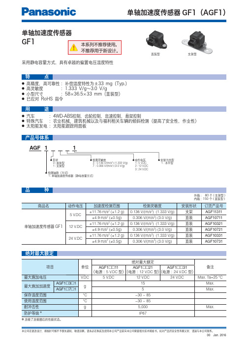
单轴加速度传感器(静电容量方式): 5 V .DC 12 V .DC 24 V .DC::123水平型:1直装型支架型:01:0.136 V/(m/s 2) {1.333 V/g}0.306 V/(m/s 2) {3.0 V/g}37AGF 单轴加速度传感器GF1● 高精度,高可靠性 :补偿温度特性为±33 mg(Typ.)● 高灵敏度 :1.333 V/g~3.0 V/g ● 小型尺寸 :58×36.5×33 mm(直装型)● 已应对 RoHS 指令种绝对最大额定采用静电容量方式,具有卓越的偏置电压温度特性● 汽车 :4WD-ABS控制,齿轮控制,怠速控制,悬架控制● 特殊汽车 :农业机械,建筑机械以及与福利相关车辆的倾斜检测(提高了安全性,作业性)● 太阳能发电 :太阳能跟踪用面板直装型外箱: 80个(支架型)内箱:150个(直装型)支架型●●注)✽1. 加速度单位[g]表示9.8 m/s2。
✽2. 连接+1.2 g与−1.2 g输出的直线输出的最大误差(AGF1◻3◻1),连接+0.5 g与−0.5 g输出的直线输出的最大误差(AGF1◻7◻1)✽3. 动作电压12 V.DC/24 V.DC型有对应钳位电压,敬请垂询。
(G)输出电压(V)−100−75−50−250255075100−40−2020406080100(°C)(mg)偏置电压变化 实测值倾斜角度 (° )(V)输出电压频率 (Hz)11060100−20−18−16−14−12−10−8−6−4−20增益−5−4−3−2−1012345−40−20020406080100(°C)灵敏度变化 实测值1. 输出特性4. 偏置电压温度特性2. 倾斜角度-输出电压特性5. 频率特性3. 灵敏度温度特性标记的商品可从网站(/ea/)下载CAD数据。
接线图Ω)■ 为了提高实际使用时的可靠性,请确认实际使用状态下的性能和品质。
KGS2速度传感器说明书
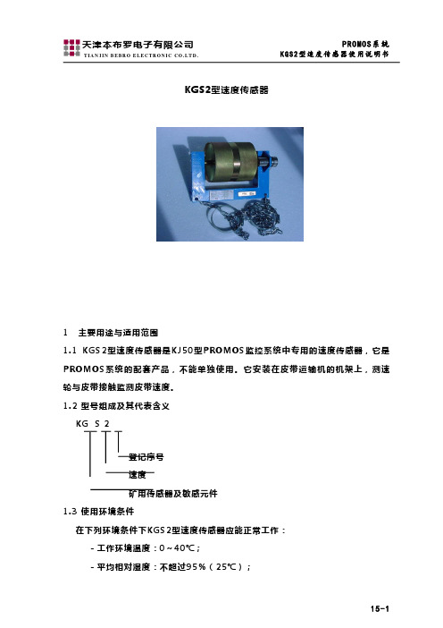
15-1KGS2型速度传感器1 主要用途与适用范围1.1 KGS2型速度传感器是KJ50型PROMOS 监控系统中专用的速度传感器,它是PROMOS 系统的配套产品,不能单独使用。
它安装在皮带运输机的机架上,测速轮与皮带接触监测皮带速度。
1.2 型号组成及其代表含义KG S 2登记序号速度矿用传感器及敏感元件1.3 使用环境条件在下列环境条件下KGS2型速度传感器应能正常工作:-工作环境温度:0~40℃;-平均相对湿度:不超过95%(25℃);-大气压力:(80~106)kPa ;-有甲烷和煤尘爆炸性危险的矿井环境中;-无破坏绝缘的腐蚀性气体的矿井中;1.4 防爆类别及标志矿用本质安全型 ExibI(150℃)。
1.5 关联设备为KDW10型矿用直流稳压电源。
(矿用隔爆兼本型)1.6 配接设备为:KJF21型控制器(矿用本安型)KCC1型系列智能I/O 接口(矿用本安型)15-2 KJK3型系列辅助控制器(矿用本安型)KTK1型系列扩音电话(矿用本安型)2 结构特征与工作原理KGS2型速度传感器主要由测速轮和KPJ1型接近开关组成。
在测速轮的端面,装有2块(或4块)磁铁,测速轮旋转时,其端面上的磁铁周期性地与KPJ1型接近开关接近,分离,使接近开关相应地通、断动作,其输出状态亦随之呈现4.7K Ω和51.7k Ω两种不同状态,PROMOS 系统通过检测接近开关的通断频率来测定皮带带速。
3 主要规格及技术参数-工作电压:8~12V DC-工作电流:Max 10mA-动作方式:KPJ1型接近开关-输出方式:输出信号的两种状态:低阻状态4.7k Ω高阻状态51.7k Ω-接线方式:与PROMOS 系统采用插接方式-连接电缆:PROMOS 系统专用4芯电缆,长度不大于90m 。
-重量 约12kg4 安装与调试KGS2型速度传感器安装在皮带运输机的下皮带处,用链条吊挂在皮带运输机架的两侧,使测速轮与下皮带接触,由皮带带动测速轮转动。
esh5型速度传感器使用说明书

esh5型速度传感器使用说明书
一、概述
ESH5型速度传感器主要用于对煤矿井下上运或下运胶带运输机因皮带打滑(失速)或超速时,对皮带机进行监控和保护。
二、技术性能及参数
l 防爆标志:ExibI;
l 大气压力:80-106kPa;周围介质温度不高于+40℃,不低于5℃;
l 周围空气相对湿度不大于95%(20±5℃);
l 在无显著摇动和冲击振动的地方;
l 在无足以腐蚀金属和破坏绝缘的气体和蒸气的环境中;
l 电网电压允许波动范围: -25% ~ +10%;工作电压:DC+12V 、电流≤80mA;
l 传感器与主机间连接电缆长度不超过500m。
具有200-1000Hz 频率和继电器触点输出功能。
三、型号及含义
ESH5测速范围, m/s霍尔原理速度传感器
四、工作原理
速度显示输出接口
采样信号处理保护输出
现场本安电源
磁钢以一定的转速划过检测面,按动按钮,此时的为正常转速(视为)
当转速50%~70%倍的转速在10s左右速度传感器动作,当转速小于等于50%或大于等于110%的转速时,速度传感器应立即输出控制信号时启动器动作。
RBSS 速度传感器 说明书

连续称重速度传感器■简介RBSS 速度传感器■应用返回皮带速度传感器(RBSS) 与皮带秤联合使用,它提供一个信号到一个积算仪并计算经过皮带运输机物料的流量。
RBSS 监视皮带运输机皮带的速度,将输出信号经电缆连接传送到积算仪。
易于与皮带秤组件紧凑地安装在一起,RBSS 提供一个在返回皮带上旋转传感器轮所产生的信号,十字杆定位在长支承梁之间,安装在返回皮带的前后托辊间。
自重保证转轮的位置在返回皮带的中间,由轮驱动的带有60 齿的测速轮,磁性传感器发出脉冲。
RBSS 的输出能用于任何皮带秤的积算仪上。
■特点结实的设计 IP65安装简单,费用低 精确的皮带速度检测■设计安装RBSS 安装连续称重速度传感器■技术规格1)RSBSS IS 认证是基于安装NAMUR 槽型接近开关(P+F#NJ0.8-5GM-N) 和适当的本安开关隔离器( 放大器)。
2)EMC 性能应要求提供。
3)接近开关和本安开关隔离器的认证为P+F 所有。
可在www.ad.siemens. com 上获得复印件。
操作方式测量原理接近开关给积算仪提供脉冲信号典型应用 混凝土皮带传输机输入双向轮旋转2 ~ 450rpm输出 • 60脉冲/转,2 ~ 450 Hz ,150.4脉冲• RBSS: 集电极开路, max. 200 mA• RBSS IS: 负载电流,0 ~ 15mA操作条件操作温度 • RBSS: -40 ~ 105 °C • RBSS IS: -25 ~ 100 °C设计拖臂喷漆低碳钢轮传感器直径127 mm ,铸铝,聚亚安酯包胶供电• RBSS: 5 ~ 18 V DC, 10 mA • RBSS IS: 5 ~ 25 V DC 从 IS 开关隔离器电缆 可选• RBSS: 3 m ,3 芯22AWG 屏蔽电缆-最大电缆长300 m• RBSS IS: 2 m ,2 芯 26 AWG ,PVC 屏蔽电缆-到IS 开关隔离器最大电缆300 m -从积算仪到IS 开关隔离器最大电缆长300m 认证RBSSCE 2)RBSS IS ( 带IS 开关隔离器或开关放大器)1)• ATEX II 2 G EEx ia IIC T6 • CSA/FM Class I, Div. 1, Groups A,B, C, and D, Class II, Div. 1,Groups E, F, and G (系统认证) • CE 2)接近开关认证(P+F#NJ0.8-5GM-N)• ATEX II 2 G EEx ia IIC T6• CSA/FM Class I, Div. 1, Groups A,B, C, and D, Class II, Div. 1,Groups E, F, and G (系统认证) 可选开关隔离器(RBSS IS 需要)3)P+F#KFA5-SOT2-Ex2 或#KFA6-SOT2-Ex2• ATEX II (1) G [EEX ia] IIC• CSA/FM: Class 1, Div. 1, Groups A,B, C, and D. Class II, Div. 1,Groups E, F, and G连续称重速度传感器■尺寸图RBSS 尺寸1)认证选项 2需要开关隔离器与皮带秤积算仪接口。
- 1、下载文档前请自行甄别文档内容的完整性,平台不提供额外的编辑、内容补充、找答案等附加服务。
- 2、"仅部分预览"的文档,不可在线预览部分如存在完整性等问题,可反馈申请退款(可完整预览的文档不适用该条件!)。
- 3、如文档侵犯您的权益,请联系客服反馈,我们会尽快为您处理(人工客服工作时间:9:00-18:30)。
湘煤立达矿山装备股份有限公司
产品使用说明书
SCGH-360矿用本质安全型转速传感器
执行标准:
GB3836-2010
版本号:V1.0
出版日期:2013-05-10
感谢您选购本产品!为了保证安全并获得最佳效能,安装、使用产品前,请详细阅读本使用说明书并妥善保管,以备今后参考。
目次
1、概述 (1)
2、工作条件 (1)
3、产品型号 (1)
4、技术参数 (2)
5、结构原理 (3)
6、安装使用 (3)
7、运输和贮存 (3)
8、订货须知 (3)
9、保修 (3)
一、概述
1、产品适用范围及用途
SCGH-360矿用本质型转速传感器(以下简称转速传感器)适用于含有爆炸性气体(甲烷)和煤尘的煤矿井下,作为一种检测装置,能够将转速信号转换为脉冲信号传送给控制器。
2、执行标准:Q/XMLD 040-2013
二、工作条件
1、在下列条件下能正常工作:
a)温度:0℃~40℃;b)湿度:≤95%;
c)大气压力:80kPa ~106kPa ;d)无显著振动和冲击的场合;
e)具有甲烷混合物及煤尘爆炸危险的煤矿井下;f)无破坏金属和绝缘材料的腐蚀性气体的地方。
g)能防止水滴渗入的地方;2、能承受的贮运条件:
a)温度:-40℃~+60℃;b)湿度:≤95%;c)振动:50m/s 2;d)冲击:500m/s 2。
三、产品型号和防爆型式
1、型号和意义
S C G
H 360
-速度
传感器本质安全型360脉冲/转2、防爆型式:矿用本质安全型;防爆标志:ExibI Mb 3、外形尺寸:mm mm mm 707994××,长宽高如图1所示。
4、安装尺寸:如图1所示5、重
量:约为0.5Kg
图1
四、技术参数
1、电气性能
a )额定工作电压:12V.DC ;
b )电压波动范围:额定电压的75%~110%;
c )工作电流:≤80mA。
2、输出信号
a )输出电阻:2K Ω;
b )最高响应频率:100KHZ ;
c )输出相位差:A、B相,位相差04590±;
d )每转脉冲数:A、B相各360P/R;
e )允许最高转速:6000r/min 。
五、结构和原理
1、结构
本安型转速传感器是将编码器装于密封的外壳内,密封的外壳上装有防水接头,作为电源线及信号线的出线用,转速传感器的主要元件:
a )中心轴:同轴旋转部件;
b )电源线:DC 12V 电源;
c )信号线:脉冲信号输出;
d )GND 线;屏蔽层接地。
2、工作原理
转速传感器,是一种通过光电转换将输出轴上的机械几何位移量转换成脉冲或数字量的传感器,由光栅盘和光电检测装置组成。
光栅盘是在一定直径的圆板上等分地开通若干个方孔,由于光电码盘与齿轮同轴,齿轮旋转时,光栅盘与齿轮同速旋转,经过发光二极管等电子元件组成的检测装置检测输出若个脉冲信号,其电路原理图如图2所示:
褐色:D C12V
输出信号
蓝色:0V
屏蔽G N D
图2
六、安装和使用
1、安装使用应放置在通风和无淋水的地方。
2、使用时,按照图2所示接线,屏蔽层可靠接地。
七、运输和贮存
1、包装后的本安型转速传感器在避免雨雪直接淋袭的条件下,可适用于水运、陆运及空运等各种运输方式。
2、包装后的转速传感器可在空气流通,温度为-10-55℃,相对湿度不大于90%的仓库中贮存。
八、订货须知
1、订货时须指明所定产品的型号、规格、数量(套)。
2、订货单位名称、详细地址、到站、联系人和电话等内容。
九、保修
本公司向用户提供终身维修服务,并做出以下有限保修保证:
自设备安装调试正常后运行之日起,一年内在正常使用、维护下,本公司将提供免费维修服务。
但由于用户原因造成设备不能按时安装者除外。
以下情况不在保修范围内:
1)由于不可抗力及外来原因(包括人为因素)引起的损坏;2)误用、意外、疏忽,未经授权的修改或修理;
3)超过使用说明书规定的权限;
4)违反操作规程。
保修范围外的维修费用,由用户负担。
