MoldWizard使用手册
任务1注塑模moldwizard设计基本操作[13页]
![任务1注塑模moldwizard设计基本操作[13页]](https://img.taocdn.com/s3/m/0631a3a5f46527d3250ce0ab.png)
按钮,系统打开“初
始化项目”对话框如图1-4所示,单击 “确
定”。
图1-4 项目初始化
5
任务1、注塑模moldwizard设计基本操作
3.注塑模设计流程
操作步骤: 操作02.建立模具坐标系 单击 按钮,系统打开“模具 CSYS”对话框如图1-5所示,选中 “产品实体中心”、“锁定Z位 置”,单击单击“确定”。
1. Moldwizard 模具设计菜单
操作步骤: 单击“开始”→“所有应用模块”→“注塑模向导”按钮,打开如图1-1
所示的“注塑模向导”工具栏。
图1-1 “注塑模向导”工具 栏
2
任务1、注塑模moldwizard设计基本操作
2.注塑模具向导的结构组成
装配结构中“cap”是产品模 型的文件名:其余特定文 件的命名形式为“cap-部 件或节点名称”如“captop-000”是整个装配文 件的顶层文件,包含了完 整模具所需的全部文件。
操作步骤: 操作04.建立工件 单击 按钮,系统打开“工件”对 话框如图1-7所示,选中“产品工 件”、“用户定义快”,修改极限 值, 单击“确定”。
图1-7工件
8
任务1、注塑模moldwizard设计基本操作
3.注塑模设计流程
操作步骤:
操作05.建立分形面
单击
按钮,系统打开“模具分形工具”对话框进行型芯和型腔创
建如图1-8所示。
图1-8模具分形工具
9
任务1、注塑模moldwizard设计基本操作
3.注塑模设计流程
单击
按钮,系统打开“检查区域
”对话框如图1-9所示,选中“计算”
单击计算器标识,系统开始对产品模型
进行分析计算,选中“面”卡,如图1-
威士迪指纹锁安装说明书
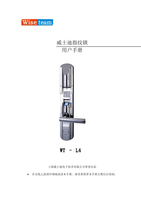
威士迪指纹锁用户手册WT – L4上海威士迪电子技术有限公司荣誉出品➢在安装之前请仔细地阅读本手册。
请妥善保管本手册方便以后查阅。
左开及右开左手开门:您站在门的外侧,当门的固定铰链在左边时,你必须用左手握住把手,拧门而入的时候,指纹锁的方向为左开。
右手开门:您站在门的外侧,当门的固定铰链在右边,你必须用右手握住把手,拧门而入的时候,指纹锁的方向为右开。
目录第一章产品介绍 (4)一、产品型号: (4)二、产品特点: (4)三、技术参数 (5)四、尺寸( MM ) (6)五、结构图 (6)六、重量(KG) (9)七、配件清单 (10)第二章功能介绍 (11)一、按键说明 (11)二、使用前的必要准备 (12)三、开门操作 (14)四、常开、常闭说明 (15)五、电池电量 (16)六、电池耗尽时应急开门 (16)七、关闭操作界面 (17)第三章操作指南 (18)一、用户管理: (18)二、系统设置 (21)三、记录查询 (23)四、开门模式 (25)第四章安装软件 (27)1、S ETUP (27)2、N EXT (27)3、B ROWSE (28)4、N EXT (28)5、F INISH (29)6、OK (29)第五章软件使用 (30)1、运行软件 (30)2、登入软件 (30)3、系统管理 (31)4、用户管理 (31)5、区域管理 (31)6、门锁管理 (32)7、前台管理 (35)第六章安装 (37)1、安装工具: (37)2、锁芯尺寸: (37)3、详细步骤: (38)第七章附录 (41)一、日常维护 (41)二、售后服务 (41)第一章产品介绍一、产品型号:守护者WT-L4型号WT –L4实物图二、产品特点:1、外形豪华、工艺精湛,、线条流畅,彰显主人高贵品味。
2、锌合金一体化结构,曲面设计,是匹配防盗门的最佳用锁。
3、功能强大,手机式操作界面,易学易用。
4、独有客人来访设计,让您的亲朋好友,同样享受高科技带来的时尚和便捷。
Moldwizard教材

从装配中移去家族成员
家族模具装配结构
—— 有两个 “PROD” 节点:一个用于 part_1 模型,另一个用于 part_2 模型, 每个节点够各有其相关文件。
模具坐标系
选择 Mold CSYS 图标
Moldwizard 假定绝对坐标系的+Z方向为出模方向,XY平面为模具装配结 构的分模面 一些产品需要重新定义相对于装配结构的正确的方位。 重新定位仅应用于“收缩率”文档的链接体。 链接体和装配的重新定位并不是 “Transform” 操作,因而保持 相关性。
收缩率值
镶件
选择 Work piece 图标
选择 Work piece 功能用于指定型腔、型芯镶件实体。 有多种方法指定型腔、型芯镶件实体:自动块、标准件、用户定义块。 能够用其他实体替换型腔、型芯镶件实体
自动的标准镶件
选择 Standard Block 选项时,有两 种方法控制镶件的尺寸和定位:距 离余量法和参考点法 能自动计算(放大收缩率后)产品 的最大轮廓尺寸。
步骤:
选择 Mold CSYS 图标 选择 WCS 下拉菜单,改变+Z方向为出模方向 移动 WCS 到分型面上。 改变 WCS 在分型面的位置(可选) 选择 OK 或 Apply。
模具坐标系位置为当前WCS的位置 模具坐标系位置为产品方块体的中心 模具坐标系位置为指定边界面的中心
收缩率
选择 Shrinkage 图标
使用模架板作为镶件
方法一:
用常用的标准镶件建立型腔和型芯镶件; 在模架板中切去镶件; 链接镶件到模架板; 加镶件到模架板上。
方法二:
在模架板上增加足够的材料厚度用做型腔和型芯镶件。偏置分型面或修改 AP_off 和 BP_off 值。 使用镶件功能链接模架板并用做型腔和型芯镶件。确保分型面足够大以能 够顺利实现修剪操作。
萨汤德斯轨迹设备用户指南说明书

This material is protected by copyright. Copying or reproduction in any manner is prohibited by law. © 2006 The Saunders Group, Inc. All rights reserved.Printed in the USA.3SECTION ONE:GENERAL GUIDELINES AND PRECAUTIONS Congratulations on your purchase of a Saunders Lumbar Traction Device.Y our new traction device is designed to provide safe and effective traction (stretching) to the lumbar region (low back).Y our traction device requires minimal assembly and is nearly ready to use out of the case.If you have questions regarding its use or to report any problems, contact your authorized Saunders traction dealer or The Saunders Group, Inc.®at 1-800-966-4308 or (952) 368-9214 or ***************************.Read these instructions completely before proceeding.Indications And Contraindications For UseDepending upon the advice of your health care provider, traction can be used to treat these conditions:•osteoarthritis•headaches•herniated discs•muscle tightness•joint stiffness•nerve root compressionTraction should not be used to treat these conditions:•acute or traumatic injury•spinal instability•fracture•rheumatoid arthritis•spinal cord compression•infections and inflammatory diseases•malignancy•any other conditions that may be made worse by movementWARNING:The sale of this device is restricted to individuals by or on the order of a licensed health care provider.The instructions provided by your health care provider should be followed precisely.Do not exceed the recommendations of your health care provider.Exceeding these recommendations may aggravate an existing condition or cause additional injury.Traction should never cause pain.A stretching sensation or some slight discomfort may be felt during treatment.Improper application of traction or the use of excessive force may aggravate an existing condition or cause additional injury.If pain is increased in the neck, back, arms or legs, or if you experience dizziness, nausea or any other type of pain or discomfort during or after treatment, discontinue use immediately and consult your health care provider before further use.Before You BeginReview the guidelines you received from your healthcare provider regarding the:•amount of traction recommended (never so much that it hurts)•duration (amount of time) of each treatment •hold and relax times if intermittent traction is recommended •number of treatments recommended per week or per dayFor lumbar (low back) traction, remove clothing, belts and accessories around the trunk and lower back area.The upper and lower stabilization belts will stay more secure if they are in contact with bare skin.Therefore, for best results, remove your shirt and slide your pants down below your hips or remove them.SECTION TWO:SET-UP AND USE - LUMBAR HOMETRAC DELUXEThis section is for set-up and use of the Saunders Lumbar HomeTrac ®Deluxe.If you have purchased a Saunders STx ®Lumbar Traction Device, proceed to Section Four on page 9.Components - Lumbar HomeTrac DeluxeMoveable (Labeled ‘Lower’)Upper Stabilization BeltLower Stabilization BeltFixed Upper Surface Hand Pump with GaugeBucklesAir CylinderCarryingHandleFigure 1. Components of the Lumbar HomeTrac Deluxe.5Open the buckles on the stabilization belts.Have a clock, timer or wrist watch availableFigure 2. J tabs. Applying Traction in Supine (Back-Lying) Position - LumbarKneel on hands and knees in an “all fours”position, on one side of the Saunders Lumbar HomeTrac Deluxe, with your head towardSlowly turn your body and sit on the LOWER surface just belowGently lower yourself so that you are lying on your side on top ofMake sure the belts are still in the correctNow, roll over onto your back.our waistline should rest on the area where the belts overlap).If desired, or as instructed by your health care provider, placepillows, wedges or bolsters under your knees, back and/or headSecure the lower stabilization belt over your bare skin first.ClickTighten the straps as snugly as Now secure the upper stabilization belt the same way.The top buckle does not have to be buckled if it is uncomfortable.Figure 3. Position Options in Supine (Back-Lying). A. Bolster under the knees for more lower back flexion(forward bending)B.Legs straight for less lower back flexionC.Wedge under lower stabilization belt for neutral low backposition or slight back extension (backward bending)A BFigure 4. Hand pump operation.A) Close-up of gauge housing;B) Both in and out motions of thepump fill the cylinder with air.First, rotate the gauge housing of the hand pump to the “PUMP”position. Begin SLOWL Y pumping air into the cylinder by stroking the pump handle all the way out and all the way in.Observe the gauge to make sure you are staying within the guidelines provided by your health care provider. DO NOT OVER-INFLATE.NOTE:If you give too much traction, rotate the gauge housing to the “RELEASE”position to let some air out of the system.Begin again by rotating the gauge housing to the “PUMP”position.When you have reached the desired amount of stretch, rotate the gauge housing to the “HOLD”position.Begin timing your treatment now, following the instructions of your health care provider.9Figure 5. Components of the Saunders STx Lumbar Traction Device. Upper Stabilization Belt Cylinder Rods from Air CylindersBuckles Hand Pumpwith GaugeCarrying Handle Moveable Lower Surface HingeFixed Upper SurfaceLower belt anchorStorageCompartmentLeft and Right Anchors forOptional UnilateralAttachmentLower Stabilization Belt11StorageY our Saunders Lumbar HomeTrac should be stored in its protective case.Replace the pump in the protective foam enclosure.Fold all belts, closing buckles where applicable.Y our Saunders STx should be stored in the closed or folded position with all components stored in the storage compartment.TroubleshootingSaunders Lumbar Traction Devices feature a very accurate, sensitive gauge.The pump is specifically designed not to leak in the “HOLD”position.If you notice a drop in the gauge reading when in the “HOLD”position it is probably because you have relaxed or moved slightly.If this happens, return to the “PUMP”position and pump back to thedesired force, then reset to “HOLD”.If the traction device loses air rapidly,there may be a leak in the system.Questions to Ask:•Is the pump in the “PUMP”position when pumping?•Is the pump in the “HOLD”position when receiving treatment?•Are you lying still? (Any movement will cause fluctuation).•Are you pumping slowly?•Are all the connections tight (i.e.hose cap, lens cap)If the unit is leaking air, try the following:•Check the air hose connections at the hand pumpand gently tighten as necessary.Do not over-tighten as the threads may strip.•Tighten the hand pump shaft sleeve cap located above theserial number label.If you have any questions, please contact your authorized Saunders Lumbar Traction Device dealer, or The Saunders Group, Inc.Customer Service Department at 1-800-966-4308 or (952) 368-9214 or ***************************.500007b。
STEP7MicroWINV4SP3使用说明书介绍
--------------项目四编程软件及其使用内容涵括:1、编程软件的初步使用2、编程软件的功能及编程方法3、调试及运转监控一、能力目标熟习掌握 V4.0 STEP 7 MicroWIN SP3的使用和编程方法,调试及运转监控。
二、所需的资料、工具和设施PLC实验板、装有STEP 7 软件的计算机、数字量输入/ 输出模块。
三、项目要求娴熟掌握可编程序控制器编程元件的符号、意义和使用,掌握各基本指令的意义和使用,学会编程软件的安装和使用。
四、学习形式以老师讲堂解说的形式学习,以学生小组的形式到实验室着手的形式实践五、原理说明STEP 7 - Micro/WIN是西门子企业特意为S7 - 300系列PLC设计开发的编程软件,可在全汉化的界面下进行操作。
它鉴于Windows 操作系统,为用户开发、编写、调试和监控自己的应用程序供给了优秀的编程环境。
其目前最新的版本是STEP7 - Micro/WIN V 4. 0 SP5 ( V4.0. 5.08 ) 。
该版本除了支持CPU的新功能外,其自己的功能也比从前的版本加强了好多。
编程软件的初步使用计算机的配置要求STEP 7 - Micro/WIN要在PC机上运转,它对PC机的最小配置要求以下:(1) 操作系统 Windows 2000 SP3 以上 ; Windows XP Home; Windows XP Professional; (2) 硬盘起码 40 MB 以上空间。
软件的安装与卸载份妥革步骤(1)将安装光盘插入 CD-ROM,在光盘目录里双击 Setup ,进入安装导游。
(2)依据安装导游的提示达成软件的安装。
软件程序安装路径能够使用默认子目录,也能够用 " 阅读 " 按钮弹出的对话框中随意选择或新建一个子目录。
(3)出现 PG/PC Interface 窗口单击OK按钮。
(4)在安装结束时,会出现下边的选项:是,我此刻要从头启动计算机( 默认选项 ) ;否,我此后再启动计算机。
MoldWizard模具设计教程

MoldWizard模具设计教程作者:lys721110UG NX MoldWizard基础教程第一课:界面的配置此教程用NX 4.0版本做讲解,从加载产品到出模具结构图,BOM表....做详细解说.老实说我有的也是边学边讲,如有不对或错漏之处,请大家指出并纠正:handshake首先我们先来认识MOLDWIZARD工具,从哪里调出来?调出MOLDWIZARD工具条的几种方法,请看视频一:项目初始化1:选择MOLDWIZARD工具条上的加载产品(项目初始化)图标2:浏览产品目录并选择产品3:按OK进入项目初始化对话框按配置__再按编辑注册器_会自动进入MOLDWIZARD装配的注册文件在这里你可添加自己的模具装配,这个有机会以后再讲:初始对话框详解如果选上了重命名对话框则按确定后会进入部件名管理对话框此处可按个人或公司的命名规则对模具组件重命名加载产品_初始化视频第一课到此为止第二课之前先熟悉下UG_MOLDWIZARD装配结构TOP: 模具最顶层装配,所有模具组件都在TOP下面VAR: 部件包含模架和标准件里用到的表达式。
标准件里用到的标准数值如螺纹孔径会存储在该部件里COOL: 用来创建冷却管道, 冷却管道的标准件也会默认放在这里.COLL分二部分,分别是SIDE_A(对应前模组件) SIDE_B(对应后模组件) FILL: 用于创建浇道和浇口MISC: 放置没有定义到单独部件的标准件, 如模架上:定位环,锁模块,撑头等.MISC也分二部分:SIDE_A(对应前模组件) SIDE_B(对应后模组件)LAYOUT: 用来放"prod" ,多腔模的LAYOUT有多个分支来安排每一个"prod"PROD: 放置产品,收缩件, 型腔,型芯……,以及顶针等。
多腔模可以使用Prod的阵列,来再利用所有prod下已经作好的子组件。
也可以放置与塑胶产品部件相关的特定部件的标准件组件,如:顶针,镶针,滑块及斜顶等。
Moldwizard模块
Moldwizard模块pdiewizard 模块,完全中文攻略!今天看到有人问,正好我知道,大家共享一下,ug 的本身汉化大家都知道了吧,比较简单!但汉化以后,你会发现Moldwizard 等其它模块汉化不完全!其实从18 版本开始Moldwizard 等模块已经带有附属的语言包(不过18的没有中文的),哈哈,只要小小的设置一下就OK 了!找到ug安装目录下的moldwizard 文件夹使用记事本打开mold_def aults.def 文件修改如下文本:MW_Lang ge:moldwizard_simpl_chinese.lng如果操作成功,OK,恭喜你,你现在使用的是完全中文版的Moldwizard 了!相应的,比如pdiewizard 模块,也有类似的设置。
如图,再不会的话,我也没办法了!造型思维*Importing image planes*Creating and importing sketches*Apply ing sketches to geometry*Creating part lines f or v is l representation讨论参数化、变量化方法1、参数化方法参数化设计(Parametric)设计(也叫尺寸驱动Dimension-Driv en)是CAD技术在实际应用中提出的课题,它不仅可使CAD系统具有交互式绘图功能,还具有自动绘图的功能。
目前它是CAD技术应用领域内的一个重要的、且待进一步研究的课题。
利用参数化设计手段开发的专用产品设计系统,可使设计人员从大量繁重而琐碎的绘图工作中解脱出来,可以大大提高设计速度,并减少信息的存储量。
由于上述应用背景,国内外对参数化设计做了大量的研究,目前参数化技术大致可分为如下三种方法:(1)基于几何约束的数学方法;(2)基于几何原理的人工智能方法;(3)基于特征模型的造型方法。
其中数学方法又分为初等方法(Primary Approach)和代数方法(Algebraic Approach)。
Woodward产品说明 - CH37171A IKD 1 I O 扩展卡说明书

应用IKD 1是一种 "智能的接线端子" 或CANbus它可以增加8个开关量输入和输出给Woodward产品例如GCP-30系列控制器供电电源................................................12/24 Vdc (6 to 36 Vdc) 内部功耗.......................................................................max. 6 W 环境温度...................................................................-20 to 70 °C 环境湿度..................................................................95 %,无冷凝开关量输入......................................................................isolated 输入范围................................................12/24 Vdc (6 to 32 Vdc) 输入电阻..............................................................approx. 6.8 kΩ继电器输出......................................................................isolated 触点材料..........................................................................AgCdO 负载 (GP)......................................................2.00 Aac@250 Vac ....2.00 Adc@24 Vdc / 0.36 Adc@125 Vdc / 0.18 Adc@250 Vdc Pilot duty (PD).....................................................................B300 ....1.00 Adc@24 Vdc / 0.22 Adc@125 Vdc / 0.10 Adc@250 Vdc 维护端口...................................................................................... 版本..................................................................................RS-232 CAN 端口........................................................................isolated 绝缘电压......................................................................1,500 Vdc 版本...............................................................................CAN bus外壳............................................................................................. DIN轨道安装.........................................extrusion profile Um 122 ................................................to snap-on on a DIN rail/C-profile ......................................................................168 × 128 × 51 mm 接线.........................................螺钉/插座根据接线端子 2.5 mm²重量.................................................................................约360 g 防护等级..............................................................没有外壳: IP 20干扰测试 (CE)..........................................................符合EN标准外形尺寸Subject to technical mocifications.2002-11-07 | IKD 1 Wiring Diagram ikd1ww-4502-ap.skfWoodwardPO Box 1519Fort Collins CO, USA 80522-15191000 East Drake RoadFort Collins CO 80525 Ph: +1 (970) 482-5811 Fax: +1 (970) 498-3058中国苏州伍德沃德控制器(苏州)有限公司 苏州工业园区苏桐路16号邮编:215021电话**************传真**************网址:中国天津伍德沃德(天津)控制器有限公司 天津北辰科技园淮河道地天泰工业园A座邮编: 300402电话*************传真*************网址: Corporate Headquarters Rockford IL, USAPh: +1 (815) 877-7441 Subject to technical modifications.This document is distributed for informational purposes only. It is notto be construed as creating or becoming part of any Woodward Governor Company contractual or warranty obligation unless expressly stated in a written sales contract.We appreciate your commentsabout the content of our publications. Please send comments including the document number below to*********************© Woodward Governor Company, 2003All Rights ReservedCH37171A- 2007/1/Suzhou 典型应用IKD 1读取数字输入量,然后通过CANbus传送给控制器(包括报警等级)。
第1章MoldWizard入门
第1章MoldWizard入门【目的】本章将用一个完整的MoldWizard设计过程作为学习MoldWizard的入门。
详细的设计过程及功能介绍将在以后的章节里进一步描述。
【目标】完成本章学习后,将能够:•启动MoldWizard应用模块。
•浏览主目录(Student Home Directory)的文件结构。
•遵循MoldWizard的整个设计项目。
•了解MoldWizard工具栏的含义。
•用MoldWizard的基本原理执行各种设计功能和程序。
【练习】练习1-1启动Unigraphics NX和Moldwziard练习1-2开始模具设计项目练习1-3设定模具坐标系练习1-4定义成型镶件(Work Piece)及多腔模布局(Layout)练习1-5分型(Parting)、定义型芯(Core)和型腔(Cavity)练习1-6加入模架(Mold Base)和标准件(Standard Parts)1.1什么是MoldWizardMoldWizard是Unigraphics NX软件中设计注塑模具的专业模块。
MoldWizard为设计模具的型芯、型腔、滑块、推杆和嵌件提供了更进一步的建模工具,使模具设计变得更快捷、容易,它的最终结果是创建出与产品参数相关的三维模具,并能用于加工。
MoldWizard用全参数的方法自动处理那些在模具设计中耗时而且难做的部分,而产品参数的改变将反馈到模具设计,MoldWizard会自动更新所有相关的模具部件。
MoldWizard的模架库及其标准件库包含有参数化的模架装配结构和模具标准件,模具标准件中还包括滑块(Slides)、内抽芯(Lifters),并可通过Standard Parts功能用参数控制所选用的标准件在模具中的位置。
用户还可根据自己的需要定义和扩展MoldWizard 的库,并不需要具备编程的基础知识。
UG NX2注塑模具设计培训教程21.2学员条件要熟练地使用MoldWizard,必须熟悉模具及其设计过程,并具备Unigraphics NX基础知识及掌握以下Unigraphics NX应用工具。
迈克罗姆电子 MixWizard 2007系列说明书

2007INTRODUCTION ............................................................................................................................................................................1MODULE SELECTION ..................................................................................................................................................................3MODULE CATEGORIES MODEL NUMBERS SIGNAL LEVELSINSTALLATION NOTESMODULE SELECTION CHART ........................................................................................................................................................5MUTING ........................................................................................................................................................................................7MICROPHONE INPUT MODULES .. (9)ML-11T Microphone/Line Input with Mute Send/Receive ......................................................................................................9M-01 Series Microphone Input ............................................................................................................................................9M-11S Microphone Input with Mute-Receive ......................................................................................................................10M-21S Microphone Input with Remote Volume Control........................................................................................................10M-41S Microphone Input with Mute-Send ..........................................................................................................................11M-51 Series Microphone Input with Voice Gate ..................................................................................................................11M-61 Series Microphone Input with Compressor................................................................................................................12M-03P High Impedance Microphone Input ..........................................................................................................................12LINE INPUT MODULES . (13)ML-11T Microphone/Line Input with Mute Send/Receive.........................................................................................................13B-01 Series Balanced Line Input ........................................................................................................................................13B-11S Balanced Line Input with Mute-Receive....................................................................................................................14B-21S Balanced Line Input with Remote Volume Control ....................................................................................................14B-41S Balanced Line Input with Mute-Send........................................................................................................................15L-01 Series Line Matching Input ........................................................................................................................................16L-11S Line Matching Input with Mute-Receive....................................................................................................................17L-41S Line Matching Input with Mute-Send........................................................................................................................17U-01 Series Unbalanced Line Input ....................................................................................................................................18U-03 Series Unbalanced Line Input with High/Low Cut Filters ............................................................................................19U-11 Series Unbalanced Line Input with Mute-Receive ......................................................................................................19U-12S Unbalanced Line Input with Variable Mute-Receive Depth ........................................................................................20U-13 Series Unbalanced Line Input with High/Low Cut Filters and Mute-Receive................................................................20U-14R Dual Input Priority with AGC......................................................................................................................................21U-21S Unbalanced Line Input with Remote Volume Control..................................................................................................21U-43 Series Unbalanced Line Input with High/Low Cut Filters and Mute-Send ....................................................................22U-61S Unbalanced Line Input with Compressor ..................................................................................................................23SPECIAL FUNCTION MODULES ..................................................................................................................................................24LINE OUTPUTT-01S Balanced Line Output................................................................................................................................................24T-02S Unbalanced Line Input with Music-On-Hold Output ..................................................................................................24T-12S Unbalanced Line Input with Music-On-Hold Output and Input Mute-Receive..............................................................25TONE GENERATORS-20S Digital Message/Tone with USB.................................................................................................................................25S-01S 1 kHz Sine Wave Test Tone ......................................................................................................................................26S-02S Buzzer/Yelp Tone......................................................................................................................................................26S-04S Switch-Selectable Tone............................................................................................................................................27REMOTE VOLUME CONTROLV-01S Remote Master Volume Control (VCA)........................................................................................................................27SPEAKER PROCESSORE-03Equalizer For F-121....................................................................................................................................................28E-04Equalizer For H-1........................................................................................................................................................28E-05Equalizer For H-2........................................................................................................................................................28E-06Equalizer For H-3........................................................................................................................................................28E-07Low Pass Filter For FB-100/HB-1.. (28)TABLE OF CONTENTSPAGE II TABLE OF CONTENTSTABLE OF CONTENTS PAGE III APPLICATIONS (30)1.Paging Over Background Music (30)2.Telephone Paging and Music-On-Hold (30)3.Banquet Room Sound System (30)4.School Gymnasium Sound System (31)5.Mute Send and Receive Combination Using Two Modules (31)FREQUENTLY ASKED QUESTIONS (31)General1.Which module should I use for a microphone?2.Which module should I use for a wireless microphone receiver?3.Which module should I use for an AM/FM tuner,cassette deck,CD player,computer sound card,juke box,mixer or satellite receiver?4.Which modules should I use for telephone or microphone paging with priority over a music source?5.Which module should I use for Music-On-Hold (MOH)?6.What type of potentiometer do I need for a Remote Volume Control module?7.How do I use one of the 900 Series processor modules?8.What is the proper wiring for the screw terminal type input modules?9.What’s the difference between the “L”Series and “B”Series modules?10.Which modules are for “mute send”?11.Which modules are for “mute receive”?Troubleshooting12.Why won't the M-11 (Microphone Input with Mute-Receive) pass signal?13.Why won't my paging source override my music source?14.Why isn't my condenser microphone working with an M Series module?15.Why is my signal level low with an L Series module?MODULAR PRODUCTS REFERENCE CHART (33)MODULE CROSS-REFERENCE CHART (34)JUMPER SETTINGS CHART (35)CONNECTOR WIRING CHART (36)INTRODUCTION PAGE 1INTRODUCTION Welcome to the TOA 900 SeriesModule Guide!In this guide,you'll find everything you need to takeadvantage of the powerful flexibility of 900 Seriesmodular products — function descriptions; signalflow and wiring diagrams; specifications; jumpersettings; application examples; and other usefulinformation.Understanding the modules will give you thefreedom to configure custom systems FAST without complicated modifications.And as your customers’needs change,you can easily add more inputs ornew functions by simply changing or addingmodules.An electronic version of the guide is also availablefor download at .Ifyou have any questions,please contact TOA ProductSupport at 1-800-733-4748 — we're here to help!TOA Electronics,Inc.Dedicated to Bob Sweet,author of the original 900Series Module Guide,1990.MODULE SELECTION PAGE 3 MODULE SELECTIONMODULE SELECTION CHART PAGE 5 MODULE SELECTION CHARTMUTING PAGE 7 MUTINGMICROPHONE INPUT MODULES PAGE 9M-01ML-11TMICROPHONE INPUT MODULESM-11M-21MICROPHONE INPUT MODULESPAGE 10M-41M-51MICROPHONE INPUT MODULES PAGE 11M-61 M-03MICROPHONE INPUT MODULES PAGE 12B-01ML-11T LINE INPUT MODULES:BALANCED PAGE 13LINE INPUT MODULESB-11 B-21LINE INPUT MODULES:BALANCED PAGE 14B-41LINE INPUT MODULES:BALANCED PAGE 15L-01LINE INPUT MODULES:LINE MATCHING PAGE 16LINE INPUT MODULES:LINE MATCHING PAGE 17L-11L-41U-01LINE INPUT MODULES:UNBALANCEDPAGE 18U-03U-11LINE INPUT MODULES:UNBALANCED PAGE 19U-12 U-13LINE INPUT MODULES:UNBALANCED PAGE 20U-21U-14LINE INPUT MODULES:UNBALANCEDPAGE 21LINE INPUT MODULES:UNBALANCED PAGE 22U-43U-61LINE INPUT MODULES:UNBALANCED PAGE 23T-01 T-02SPECIAL FUNCTION MODULES:LINE OUTPUTPAGE 24SPECIAL FUNCTION MODULEST-12S-20SPECIAL FUNCTION MODULES:LINE OUTPUT PAGE 25SPECIAL FUNCTION MODULES:TONE GENERATORS-01 S-02SPECIAL FUNCTION MODULES:TONE GENERATOR PAGE 26S-04V-01SPECIAL FUNCTION MODULES:TONE GENERATOR PAGE 27SPECIAL FUNCTION MODULES:VOLUME CONTROLE-03 E-04 E-05 E-06 E-07E Series Processor Modules for TOA SpeakersSPECIAL FUNCTION MODULES:SPEAKER PROCESSORPAGE 28E-03E-04E-05E-06E-07SPECIAL FUNCTION MODULES:SPEAKER PROCESSOR PAGE 29E SeriesProcessor Modules for TOA SpeakersAPPLICATIONSPAGE 30APPLICATIONSAPPLICATIONS PAGE 31FREQUENTLY ASKED QUESTIONSFREQUENTLY ASKED QUESTIONSPAGE 32FREQUENTLY ASKED QUESTIONS (continued)MODULAR PRODUCTS REFERENCE PAGE 33MODULE CROSS-REFERENCEPAGE 34Notes:• H Series microphone modules do not provide phantom power.• Original mute-type modules (pre-1994) connect to Mute Bus #1 only.Newer "MK2" mute-type modules connect to both Mute Bus #1 and Mute Bus #2 and have a "MK2" label on the module faceplate.JUMPER SETTINGS PAGE 35Note:1.In many applications,NO jumper changes are required.Mute-Receive and Mute-Send modules connect to both Mute Bus #1 and Mute Bus #2by default.2.Configure the M-11S Mute Response Mode before use - it will not pass signal out-of-the-box.CONNECTOR WIRING PAGE 36TOA E LECTRONICS, I NC.TEL: 800-733-7088FAX: 800-733-9766TOA C ANADAC ORPORATIONT EL: 905-564-3570F AX: 905-564-3569© 2007, TOA Electronics, Inc.。
examWizard用户指南说明书

User guideHow to use examWizard Step-by-step process A step-by-step guide to using examWizard, a free exam prepa-ration tool containing a bank of past exam questions, mark schemes and examiners’ reports.How to login?Initially you will be presented with the homepageStep 1 – From the homepage, select either a GQ or BTEC subject or sectorStep 2 – Select your subject from the drop-down menu on the Home page click Login.Step 3 – L ogin using your EdexcelOnline or QMA account details (available free to all teachers of Edexcel specifications).N.B. Ask your Examinations Officer if you unsure of you’re username and password.Click below to go to the section you wantFind Past PapersSearch for past exams papers, mark schemes and examiner’s reports.My PapersView and edit tests that you have preciously created,and view past papers that you saved.Build A PaperSearch for questions, then build your own homework activity, test or mock exam.FAQCheck out our most frequently asked questions.Find Past PapersStep 1– Click on the Find Past Papers tab and select to list all past papers.Step 2– You can use additional search criteria to narrow down your search. Click Search to bring up your results.Continue to Step 3Step 3– The results can be sorted byclicking on the column headers.Clicking on a past paper will display a newwindow, with the following tabs showing:• Paper• Mark Scheme• Examiner’s ReportEach of these can be exported in PDFformat, to store on your computer andprint out later.Step 4– To export the past exam paper, mark scheme or examiner’s report select the Export button.If a paper includes additional materials (such as resource booklets or formulae sheets), these are included in an additional Resources tab.Please note: some of these files are quite large, so may take a short while to load.Build a paperStep 1– Click on the Build a paper tab and select qualification.Step 2– Use the different search filter options to find the questions you need and click Search.Step 3– Results options are presented in the left side panel, View, Add and Remove various question to start to build your paper.Continue to Step 4Step 4– Preview questions by clicking View/Edit and naming your paper.This section will tell you the details of how your paper is progressing, with indications of number of questions, overall time to complete and overall marks given.Details on Questions, Mark Scheme and Examiner report are also given here.Step 5– Once the paper is completed you can save and view your papers in the My Paper section ready to edit, export, delete or print.My PapersOnce saved, your custom paper will remain in the My Papers area for you to come back and retrieve, edit, or copy.Step 1– Click on the My Papers tab to view and editCustom papers include an automatically generated mark scheme and examiner’s report, based on the questions included.Step 2– To preview the custom paper, click on the paper name. The custom paper will open in a new browser window.Step 3– To print it, or export it to MS Word or PDF, select the Print icon.Step 4– To edit it, select the Edit icon. You will be then be taken to the Build a Paper tab where you can edit your paper by adding, deleting and re-ordering questions.Please note: You will need to save your changes by clicking the Save button on theMy Exam Paper panel.Step 5– Create a copy of your paper and edit the new version. Simply select the Copy icon next to paper you want to update.FAQsHow do I print or export my custom paper to MS Word or PDF?You can print your custom paper two ways:1. Once your custom paper is ready but not yet saved, you can print it by clicking theExport button that appears on the My Exam Paper panel on the Build A Paper tab.2. Once your custom paper is saved, you will be able to print it from the My Paperstab by clicking the Print icon that appears next to your paper.In both cases you will be presented with three options:• Print• Export to Word• Export to PDFYou can also add a cover sheet to your papers before printing.How can I increase the question area?You can minimise or maximise Search Results panel area by clicking the arrowicon ().Can I edit custom papers I have already created?Yes. Go to the My Papers tab and select the Edit icon that appears next to the custom paper you would like to edit. You will be then taken to the Build a Paper tab where you can add, delete and reorder questions.How can I download additional resources onto my local computer?Open a custom paper with resources and click on the Resources tab. Select theresource you would like to download by clicking on it. Depending on your browser’s settings, the downloaded resource can appear at the bottom of your browser window or you will get the open/save pop-up window.Can I use examWizard for more than one subject?Yes. You must select a subject before logging in, but you are not restricted as to which subject you can choose. You can change a subject on Home page.If you have any further questions about examWizard and how it can benefityou and your learners, Please contact your Account Manager or email*************************.PEUK C0126 Version 2.0 March 2022 DCL1: Public。
Moldwizard(2)_NX1

如果复制到型腔和型芯的曲面的总和不等于产品 模型的所有曲面数量,则边界曲面不正确。
有两种指定区域边界的方法:边界曲面和边界边 缘。
在提取区域之前,横跨分型线或分型面的曲面应 该先被分割,因为这些曲面一部分在型芯,另一 部分在型腔。可以拖动滑板发现渗漏区域,检查 区域边界。
当发现渗漏区域在补丁面时,可以增加建模公差, 这有助于 Moldwizard 发现在补丁面附近的正确边 界。
广州UG华南培训中心 2003-10-16
Moldwizard
分型
选择 Parting 图标
型腔块
型腔修剪片体
分型是创建基于塑胶产品的型腔和型芯 的过程。 Moldwizard 基于修剪法(Trim Based Cavity and Core)分型。 在 Trim Based Cavity and Core 方法中,先 创建一组分型面,并复制后,分别与独 立的一组型腔曲面和型芯曲面缝合在一 起。
列出所有分型线;
改变特定组的面的颜色; 根据新指定的“拔模角度极限”或“最小角度极限”重新计算并更新结果。
菜单功能
序号 选项 功能 用来计算小于指定拔模角度且足于出模的面,仅接 受角度值为0<a<90。输入角度值,按Apply即可。 根据设置的角度值计算穿越面,仅接受角度值为 0<a<90。输入角度值,按Apply即可。 包括10种类型的曲面。当选择Apply时,如果激活开 关时,将高亮显示相应类型的曲面,并计算这些曲 面的数量。 激活开关,可以改变相应曲面的显示颜色。 激活开关后,选择指定的颜色高亮显示曲面。
3
Negative Faces
4 5 6
在产品实体模型高亮显示小角度曲面并计算这些面 Small Angle Faces 的数量。小角度曲面是指小于指定拔模角度的那些 曲面,但不包括垂直曲面。 Vertical Faces Crossover Faces 法向垂直拔模方向亦即拔模角度为0的曲面。 “穿越面”是指同时具有正向和反向的曲面。在产 品实体模型高亮显示具有最小绝对角度的面并将列 出超过指定角度的曲面的数量。
IMOLDV6简单教程

SolidWorks模具设计实验指导前言在二十一世纪,世界制造加工业的竞争更加激烈对注塑产品与模具的设计制造提出了新的要求。
产品需求的多样性要求塑料产品设计的多品种,复杂化。
市场的快速变化要求发展产品及摸具的快速设计制造技术。
全球性的经济竞争要求尽可能的降低产品的成本,提高产品的质量。
创新,精密,复杂,高附加值已成为注塑产品的发展方向,必须寻求高效可靠敏捷柔性的注塑产品与模具设计制造系统。
SolidWorks是三维机械设计软件市场中的主流软件。
它是终端工程应用的通用cad平台。
Imold是SolidWorks软件的摸具插件专门用来进行摸具设计的。
在校学生能掌握一款三维模具设计软件是十分必要的。
基于同学们的基础和实际操作能力,我们选择了SolidWorks2005-Imold作为实验软件。
相信同学们通过本实验的学习能够掌握并熟练使用Imold2005进行注塑摸具设计。
第一部分: imold的介绍第一章 imold使用:打开solidworks2005,单击主菜单中的工具选项再点击插件选项,出现如图1-1所示对话框勾选imoldv6选项,(1-1)单击确定。
出现如图1-2的工具条。
(1-2)在imold模块中进行模具设计时,经常需要访问零件和装配体各种信息,如果设置轻化状态,这些信息不能进行正常访问。
如果设置了轻化在imold需要使用这写信息时,系统将耗费大量时间来进行检查和还原因此建议取消轻化。
单击solidworks菜单中工具——选项如图1-3所示点击大型装配体在把自动轻化选项去掉。
如图1-4。
(1-3)(1-4)第二部分 摸具设计实验指导第一章 数据准备和项目建立:1.1 数据准备单击数据准备—选择塑料制件如图1-1所示。
(1-1)在衍生工具条中,旋转y 项选择90度,y 方向取反,单击确定。
参数设置如图1-2。
使z 轴垂直于分型面箭头方向如图1-2-1所示(1-2) z 轴必须与自己设计的分型面垂直否则在分型操作时分型面和分型方向将出现错误。
UG-MoldWizard使用手册

UG-MoldWizard使用手册UG/ MoldWizard使用手册(1)引言MoldWizard是什么?MoldWizard是针对注塑模具设计的一个过程应用 . 型腔和模架库的设计统一到一连接的过程中 .MoldWizard 为建立型腔 , 型芯 , 滑块 , 提升装置和嵌件的高级建模工具方便地提供快速 , 相关的 , 三维实体结果 .在 MoldWizard中 , 模具相关概念的知识 _ 型芯和型腔, 模架库和标准件_是用如 UG/WAVE和 Unigraphics主模型的强大技术组合在一起 .优点 :●过程自动化●易于使用●完全的相关性 .主要程序 :●准备○装载产品模型/模具坐标系/计算收缩率 /设定毛坯尺寸 /中心布局 .●型芯和型腔○搜索分模线 /建立分模面 /修补孔/抽取区域 /建立型芯和型腔.●模架库和标准件用户介面 User Interface○引导你通过为完成你的模具设计的一个合理的行进步 .选择Mold CSYSUG/ MoldWizard使用手册(3)计算收缩率Shrinkage建立一收缩部件 ,在产品模型与收缩部件间的相关联关系使得在模型上的工作继续能更新收缩部件.收缩是作用到收缩部件上的一个比例因子去补偿当冷却时部件的收缩.注:选择计算收缩率( shrinkage) 图标自动地导航装配和设置收缩部件为工作部件部件.设定毛坯尺寸Insert Box定义一个将被用于定义型腔和型芯毛坯尺寸的容积.设定毛坯尺寸功能通过测量部件和建议一可被调整的适当尺寸建立毛坯块 .UG/ MoldWizard使用手册(4)布局Layout用于在模具装配结构中添加 , 移去或重定位型腔 ,在这个过程中产品子装配树被操纵. 注 :布局功能主要用于多型腔模具工具UG/ MoldWizard使用手册(5)分模分模是基于一塑料的部件模型建立型芯与型腔的过程. 当你选择分模 (Parting) 图标时 , 显示部件将自动地改变到当前分模部件 .注 :●新的分模功能○自动搜索分模线○自动寻找补丁环○自动打补丁○产品设计顾问UG/ MoldWizard使用手册(6)模架库UG/ MoldWizard使用手册(7)标准件注 :标准件包括顶杆 , 型芯销 , 定位环和注口 , 螺钉, 锁块 , 导向柱…注 : __顶杆后处理用分模面修剪顶杆调整顶杆长度UG/ MoldWizard使用手册(8) Misumi 标准○对每种标准件许多的更改许多条件约束 , 如D/2<DKC<H/2UG/ MoldWizard使用手册(9)滑块与顶块部件设计步骤 :○块形状由 Mold Tools来实现○设置块中心线的方向○加入座的标准件○重定位标准件○调整块座尺寸○链接块形状到座 , 并加到目标体上○必要时调整模架尺寸.嵌件例子 :UG/ MoldWizard使用手册(10)浇口●平衡式 / 非平衡式○位置 : 型芯侧 /型腔侧○浇口原点○8 种类型浇口有效 .浇口类型 :UG/ MoldWizard使用手册(11)流道流道设计步骤 :○定义流道路径的引导线○投射引导线到分模面○选择流道截面形状建立流道 .UG/ MoldWizard使用手册(12)UG/ MoldWizard使用手册(13)电极设计例UG/ MoldWizard使用手册(14)建腔Create Pocket 的功能在模板 , 型芯 , 型腔等需要安装标准件的部位建立空腔并留出相应的间隙 . 把标准件作为工具体 , 模架上所有与该标准件相交的零件都会自动地减去该标准件, 并保持其形状和尺寸与之相关.Target+Standard __先选目标体 (模板 , 型芯 , 型腔 ),Ok 或Apply之后 , 再选准件 .Target Body___选择目标体, 所有与之相交的标准件都将作为工具体自动被减掉 .Standard Part___当一个标准件被选中后 , 就把该标准件作为工具体 , 所有与之相交的模板 , 型芯 , 型腔等都将作为目标体自动减去该标准件.参数预设置___在 moldwizard/mold_defaults.def 文件中设置●项目单位●目录路径●文件命名●层和颜色●处理选项。
MW用户手册

ModelWizard(含Print it)用户手册Tier Time北京太尔时代科技有限公司2005.6目 录第 1 章 软件简介 (1)1.1 功能简介 (1)1.2 运行环境 (3)第 2 章 启动ModelWizard (4)2.1 安装 (4)2.2 启动 (4)2.3 载入STL模型 (5)2.4 载入CSM和CLI模型 (6)2.5 打印 (7)第 3 章 显示 (8)3.1 显示模式 (8)3.2 投影方式 (9)3.3 视图变换 (9)3.4 剖面显示 (11)第4 章 三维模型操作 (12)4.1 坐标变换 (12)4.2 处理多个三维模型 (13)4.3 三维模型合并,分解及分割 (14)4.4 STL模型检验和修复 (16)4.5 三维模型的测量和修改 (18)4.5.1 测量 (18)4.5.2 修改 (19)第 5 章 分层 (21)5.1 分层前的准备 (21)5.2 分层参数详解 (21)5.3 分层 (24)第 6 章 层片模型 (25)6.1 显示CLI模型 (25)6.2 在二维模型窗口显示 (26)6.3 设定成型位置 (26)第 7 章 三维打印/快速成型 (28)7.1 熔融挤压工艺原理 (28)7.2 三维打印机命令 (29)7.3 手动调试 (30)7.4 打印流程 (31)7.5 准备打印 (31)7.6打印模型 (32)7.7系统工作状态,指令动作 和 错误消除方法 (32)附录A 命令参考 (34)A.1 菜单 (34)A.2 工具条 (36)附录B 从CAD系统输出STL文件 (39)附录C 安装PMAC数控卡及驱动 (43)C.1 安装数控卡的驱动程序: (43)C.2 在串口(COM1)上安装数控卡 (43)附录 D 系统参数 (48)附录 E 系统状态、故障及解决方法 (49)第 1 章 软件简介一键打印 +丰富功能ModelWizard(含Print It)是三维打印/快速成型软件,它接受STL模型,进行分层等处理后输出到三维打印/快速成型系统,可以方便快捷的得到模型原型。
安川变频器调试开始DriveWizard按照下面的方向开始使用DriveWizard
2开始DriveWizard加上按照下面的方向开始使用DriveWizard: 2.1启动程序有三种方法可以启动一个会话DriveWizard加上:从开始菜单从快捷・・・通过双击一个项目文件。
2.1.1从开始菜单遵循这些指令从开始菜单中打开DriveWizard加上:1)打开开始菜单在Windows任务栏。
2)去编程菜单,打开编程文件夹。
3)打开文件夹标记为“YE_Applications”。
4)选择“DriveWizard加上2.1.2从捷径双击快捷方式“DriveWizard +”标志2.1.3双击项目文件DriveWizard加上可以通过双击打开一个项目文件。
1)打开Windows资源管理器2)双击项目文件的图标。
注意:项目文件保存到桌面也可以用来打开一个会话DriveWizard加上通过双击图标。
2.2连接驱动和PC通过Com端口DriveWizard加上首次打开时,启动窗口所示将出现在电脑显示器上。
第一个窗口出现问如果用户想连接到驱动器或打开一个项目文件。
连接:电脑连接到驱动编辑参数和执行测试运行。
打开项目文件:驱动器并不一定需要连接到编辑一个项目文件。
连接一个驱动器,DriveWizard加上要求某些数据输入“连接设置”和“协议设置”1)指定连接设置端口选择驱动的com端口连接。
DriveWizard加上将列出可用的com端口正在使用的电脑。
这电脑显示会有所不同。
媒体选择的媒体设置com地址:搜索或单身。
如果你知道com地址,进入这里。
如果不是,选择“搜索”和DriveWizard加上会自动搜索地址。
地址设置com地址驱动参数设置。
这个设置将显示为灰色,当“搜索”已经选定的媒体。
2)选择协议设置集驱动的通信速度和电脑。
这些设置不同的驱动模型,参考说明书是否正确设置。
个基点选择1200个基点,2400个基点,4800个基点,9600个基点,19200个基点,38400个基点,57600个基点,76800个基点,115200个基点平价选择None,奇怪,甚至数据长度7位/ 8位停止位1位/ 2位3)选择“连接”DriveWizard加上将尝试连接到驱动器。
Vollrath 68 英寸传送带披萨炉(模型 JPO14、JPO18)操作手册说明书

68 Inch Conveyor Pizza OvensModels JPO14, JPO18© 2017 The Vollrath Company L.L.C. Part No.350842-1 en11/24/17Register your product at /registration and become eligible to win a free 10" Vollrath Tribute® fry pan.Thank you for purchasing this Vollrath equipment. Before operating the equipment, read and familiarize yourself with the following operating and safety instructions. SAVE THESE INSTRUCTIONS FOR FUTURE REFERENCE. Save the original box and packaging. Use this packaging to ship the equipment if repairs are needed.SAFETY PRECAUTIONSTo ensure safe operation, read the following statements and understand their meaning. This manual contains safety precautions which are explained below. Please read carefully.Warning is used to indicate the presence of a hazard that will or can cause severe personal injury or death.Caution is used to indicate the presence of a hazard that will or can cause minor or major personal injury if the caution is ignored.NOTICE:Notice is used to note information that is important but nothazard-related.To reduce risk of injury or damage to the equipment•Plug only into grounded electrical outlets matching the voltage on the rating plate.•Use this equipment in a flat, level position.•Unplug equipment and let it cool before cleaning or moving. Equipment remains hot after it is turned off.•Unplug when not in use.•Keep equipment and power cord away from open flames, electric burners or excessive heat.•Do not operate unattended.•Closely supervise equipment operating in public areas and/or around children.•Do not operate if equipment has been damaged or is malfunctioning.FUNCTION AND PURPOSEThis equipment is intended to bake fresh dough and par baked pizza and flat breads - one at a time. It is not intended to bake frozen pizza, deep dish pizza or cook raw food or raw toppings. It is intended for use in commercial foodservice operations that serve pizzas, but that also have other menu items. It is intended for occasional, not continuous use. It is not intended for pizzerias. It is not intended for household, industrial or laboratory use.CLEARANCE AND ENVIRONMENT REQUIREMENTSDo not place this oven on surfaces or near walls, partitions or kitchen furniture unless they are made of non-combustible material or clad with non-combustible heat-insulating material. This oven must not be used near or below curtains and other combustible materials. Do not place the oven adjacent to a heat producing appliance.WARNINGCAUTIONItem No.ModelDescriptionPO4-20814L-R JPO1414" Wide Left to Right Conveyor, 208V PO4-20814R-L 14" Wide Right to Left Conveyor, 208V PO4-22014L-R 14" Wide Left to Right Conveyor, 220VPO4-22014R-L 14" Wide Right to Left Conveyor, 220V PO4-24014L-R 14" Wide Left to Right Conveyor, 240V PO4-24014R-L 14" Wide Right to Left Conveyor, 240V PO4-20818L-R JPO1818" Wide Left to Right Conveyor, 208V PO4-20818R-L 18" Wide Right to Left Conveyor, 208V PO4-22018L-R 18" Wide Left to Right Conveyor, 220VPO4-22018R-L 18" Wide Right to Left Conveyor, 220V PO4-24018L-R 18" Wide Left to Right Conveyor, 240V PO4-24018R-L18" Wide Right to Left Conveyor, 240V2 68 Inch Conveyor Pizza Ovens Operator’s Manual – Models JPO14, JPO18SET UP1.Place the oven on a hard, flat, stable surface.2.Install the legs.Two people required. Have one person lift one end of the oven while the other person installs the legs. Repeat for the other side of the oven.NOTICE:Legs must be installed. Failure to install the legs willrestrict airflow and cause the oven to overheat.3.Install the load and unload trays to match the conveyor direction. The load tray slants toward the conveyor. The unload tray slantsaway from the conveyor.FROZEN/FRESH DOUGH HANDLING TIPSThe following are general tips. Follow any instructions specific to your brand of dough or recipe.•Remove the wrapping from frozen dough balls.•Place the dough balls a few inches apart, into a proofing box or on a sheet pan.•Lightly spray top of the dough balls with a non-stick cooking spray, then cover with a layer of freezer paper. •Refrigerate over night.•Only remove enough dough balls from the sheet pan to accommodate what you will need for a few hours.•Sprinkle flour, cornmeal or Pizza Crisp onto the surface on which you plan to roll out the dough.•Roll the dough, starting from the center and working your way to the outer edges. Turn the dough as you work toward the outer edges to maintain a round shape.•Use a rolling pin, dough press or dough sheeter to form the dough to the desired size and thickness.•Place the flattened shell onto a dark metal or seasoned pizza screen or pan.NOTICE:Fresh dough pizzas must be baked on metal pizzascreens or pizza pans. Do NOT put fresh dough pizzas directly on the conveyor. Dough will stick to or fall through the conveyor.NOTICE:Do NOT use paper pizza pans in this oven. Paper pizzapans will burn and could create a fire hazard.NOTICE:Dark metal or seasoned metal pans perform best. Shinymetal or aluminum foil will reflect heat away from the pizza and preventing browning.PIZZA ASSEMBLY TIPS•Spread the sauce, starting from the center and moving toward the outer edges of the crust to ensure a uniform thickness of sauce. Leave an inch of space to the outer edge of the crust to allow the crust to brown. Spreading sauce too close to the edge prevents the crust from browning.•Spread out high moisture content toppings, such as vegetables. High moisture toppings will prevent the surrounding areas from baking until ALL of the moisture has evaporated.68 Inch Conveyor Pizza Ovens Operator’s Manual – Models JPO14, JPO183FEATURESBEFORE FIRST USE1.Clean the oven. See “Daily Cleaning” on page 4.OPERATIONThe crumb trays must be installed in the oven duringoperation. Failure to install the crumb trays will cause the oven to overheat.Preheat1.Plug the oven into a grounded electrical outlet that matches the rating on the name plate found on the oven.NOTICE:Using a voltage other than the nameplate rated voltagewill cause damage to the unit. Incorrect voltage,modification to the power cord or electrical components can damage unit and will void the warranty.2.Adjust the entry and exit heat shields to allow pizzas to pass into the oven, and to regulate the amount of heat retained at each end of the oven to achieve desired results. Tips:3.Press the ON/OFF toggle switch to the ON (I) position.4.Set the top and bottom heat controls and conveyor speed.Tip: Set the bottom heat approximately 75° to 100° degrees hotter than the top control.5.Wait 20 minutes for the oven to preheat.TestNOTICE:Fresh dough pizzas must be baked on metal pizza screensor pizza pans. Do NOT put fresh dough pizzas directly on the conveyor. Dough will stick to or fall through the conveyor.NOTICE:Do NOT use paper pizza pans in this oven. Paper pizza panswill burn and could create a fire hazard.NOTICE:Dark metal or seasoned metal screens and pans performbest. Shiny metal or aluminum foil will reflect heat away from the pizza and preventing browning.1.Test the settings by placing a sample pizza into the oven.2.Monitor the baking process and adjust the temperatures and conveyor speed to prevent the pizza from burning.3.Evaluate the results.Bake1.Adjust the top and bottom heat control settings and conveyor as needed to achieve desired results. Allow time for the oven to adjust to new heat settings before placing a pizza on the conveyor .2.Do not overload the oven. Wait a few minutes for the oven to recover before placing the next pizza onto the conveyor. Maximum oven capacity: If a Pizza is Stuck in the Oven1.Position the ON/OFF switch to the OFF (O) position and unplug the oven.2.Let the oven cool completely.e tongs to remove the pizza. Take care to not bump the glass heating elements above and below the conveyor.CGHAABBDLeft to Right Conveyor Set-up ShownE F A Heat Shields B Crumb TraysC Load / Unload Trays Load Slants toward conveyor Unload Slants away from conveyorD Reset Button (Reference only. See page 4.)E On/Off SwitchO Off Position I On Position F Top Heat Control Knob G Bottom Heat Control Knob H Conveyor Speed KnobCAUTIONBurn HazardDo not touch the equipment while it is heating or operating. Hot surfaces can burn skin.Pizza Type SuggestionsFresh Dough Entry shield all the way down, and exit shield partially down to retain heat to bake the dough.Par BakedEntry and exit shields open to finish crust and brown the toppings.JPO14 Models One 12" diameter pizza or multiple smaller pizzas with a combined maximum diameter of 12".JPO18 ModelsOne 16" diameter pizza or multiple smaller pizzas with a combined maximum diameter of 16".4 68 Inch Conveyor Pizza Ovens Operator’s Manual – Models JPO14, JPO18CLEANINGNOTICE:Do not use abrasive materials, scratching cleansers orscouring pads to clean the exterior of the equipment. These can damage the finish.Daily Cleaning1.Press the ON/OFF switch to the OFF (O) position and unplug the oven.2.Let the oven cool completely.3.Slightly dampen a soft cloth with a warm water.e the dampened cloth to clean the exterior of the oven, the air intake under the oven, the load and unload trays.Clean the Conveyor1.Plug in the oven.2.Press the ON/OFF switch to the ON (I) position3.Rotate the top and bottom heat control knobs to the lowest setting.4.Rotate the conveyor speed knob to 10.5.Press and hold a heat resistant (steel wool, metal wire brush, etc) abrasive pad or brush against the conveyor. Move the pad or brush back and forth (left to right) across the conveyor to remove food debris.6.Empty and clean the crumb trays.PREVENTATIVE MAINTENANCEContact an authorized service agent for a professional cleaning of the components.WARNINGElectrical Shock HazardDo not spray water or cleaning products. Liquid could contact the electrical components and cause a short circuit or an electrical shock.Burn HazardAllow equipment to cool before moving or cleaning.Burn HazardCrumb trays may be hot. Use oven mitts to protect hands.TROUBLESHOOTINGProblemMight be Caused By Course of Action Oven does not heat and the conveyor belt does not move.Oven is not plugged in.Plug in the oven.Oven is not turned on.Press the ON/OFF switch to the ON (I) position.The wall breaker may be tripped.Reset the breaker.The reset may be tripped.Look under the oven to see if an object is preventing the fan blades from turning.1.Press the ON/OFF switch to the OFF (O) position.2.Unplug the oven.3.Wait 30 minutes for the oven cool.4.Remove the object.5.Plug in the oven.6.Press the ON/OFF switch to the ON (I) position.7.Press the reset button.8.If the problem persists call Vollrath Technical Services.Inspect the fan blades to see if they are dirty.1.Press the ON/OFF switch to the OFF (O) position.2.Unplug the oven.3.Wait 30 minutes for the oven cool.4.Clean the fan blades.5.Plug in the oven.6.Press the ON/OFF switch to the ON (I) position.7.Press the reset button.8.If the problem persists call Vollrath Technical Services.Oven heats and the conveyor belt does not move.There may be a problem with the motor/speed control or drive chain.Contact Vollrath Technical Services.Top or bottom heater tubes do not heat.One or more heater tubes may haveburned out.Contact Vollrath Technical Services.There may be a problem with the top orbottom heat switch.Top and/or bottom heat remains on when the power switch is in the OFF position.There may be a problem with the relayfor the heat controlContact Vollrath Technical Services.Oven repeatedly overheats.The crumb trays may not be installed.Verify the crumb trays are installed.The fan may be dirty. Verify the fan blades are clean.There may be a problem with the fan.Run the oven for 10 minutes. If the fan does not run, contactVollrath Technical Services.The fan is not running.There may be a problem with the fan orfan switch.Run the oven for 10 minutes. If the fan does not run, contact Vollrath Technical Services.The oven is turned off and the fan is running.Normal operation. The fan turns on as needed to cool the oven._TROUBLESHOOTING (CONTINUED)Problem Might be Caused By Course of Action68 Inch Conveyor Pizza Ovens Operator’s Manual – Models JPO14, JPO185© 2017 The Vollrath Company L.L.C.Part No.350842-1 en 11/24/17The Vollrath Company, L.L.C.1236 North 18th StreetSheboygan, WI 53081-3201 U.S.A.Main Tel: 800.624.2051 or 920.457.4851Main Fax: 800.752.5620 or 920.459.6573Customer Service: 800.628.0830Canada Customer Service: 800.695.8560Technical Services******************************Toasters: 1-800-309-2250All Other Products: 800.628.0832SERVICE AND REPAIRWhen under warranty, repair is available for this product. To begin the process:1.Contact Vollrath Technical Services at 1-800-309-2250. Please be ready with the item number, model number and serial number. You can find this information on the nameplate located on the side or back of the equipment. Also please provide a proof of purchase indicating the date the equipment was purchased.2.A technical services representative will help you troubleshoot the problem over the phone.3.If the representative determines the issue requires professional service, he or she will help you locate an authorized service center.4.Contact the authorized service center to make arrangements for the repair. Vollrath will cover the cost to repair and/or replace defective parts within the equipment warranty period.WARRANTY STATEMENT FOR THE VOLLRATH CO. L.L.C.The Vollrath Company LLC warrants the products it manufactures or distributes against defects in materials and workmanship as specificallydescribed in our full warranty statement. In all cases, the warranty runs from the date of the end user’s original purchase date found on the receipt. Any damages from improper use, abuse, modification or damage resulting from improper packaging during return shipment for warranty repair will not be covered under warranty.The warranty does not apply to products purchased for personal, family or household use, and The Vollrath Company LLC does not offer a written warranty to purchasers for such uses.Warrantied Parts: The warranty period is 2 years parts, 1 year labor.Heater Tubes: The warranty period is 1 year, including labor. Heater tube glass damage is not covered by this warranty.For complete warranty information, product registration and new product announcements, visit .。
MotorSolve 4.0 使用手册

海基科技
1
目录
1 MotorSolve 界面..........................................................................................................................3 1.1 整体界面............................................................................................................................3 1.2 命令栏................................................................................................................................4 1.3 设计栏................................................................................................................................6 1.4 结果分析栏........................................................................................................................9 1.5 材料栏..............................................................................................................................10 1.6 工作区.............................................................................................................................. 11
Isys Micro Sandwich Regulator V461P 安装与维护指南说明书

Application Limits
These products are intended for use in general purpose compressed air systems only. Operating Pressure Range: Maximum 145 PSIG (1000 kPa) Ambient Temperature Range: -15°C to 49°C (5°F to 120°F)
Isys Micro Sandwich Regulators
Cap Screw, M2.5 Hex Torque 4-6 In-lbs
Valve Module
Tie Rod, Torque Snug Pressure Gauge 0-120 PSI or 0-0.8 Mpa Regulator Module 145 PSI Max
Install Sandwich Regulator:
1. Place the Sandwich Regulator at the desired manifold location. Take care when engaging the electrical plugs.
Click here to view bookmarks.
Pneumatic Division Richland, Michigan 49083 269-629-5000
! WARNING
• To avoid unpredictable system behavior that can cause personal injury and property damage:
Moldwizard其他功能

1.2 冷却系统
三种修改通道的方式:连接通道、延伸通道、调整通道
1.2 冷却系统
三种冷却的方式:冷却连接件、冷却回路、冷却标准部件库
1.3 电极系统
在模具的型芯、型腔或嵌件中,常有一些形状复杂的区域, 很难加工,此时往往采用电极来加工这些复杂区域。电极的材 料通常采用紫铜、黄铜或石墨。
单击【注塑模向导工具】工具条中设计
在曲线上移动点
1.1 浇注系统
• 1.1.3 分流道(Runner)
分流道是连接主流道和浇口的桥梁, 起分流和转向作用。分流道必须在压力 损失最小的情况下,将熔料以较快速度 送到浇口处充模。对于设计分流道,有 一个总的设计原则:必须保证分流道的 表面积与其体积之比值尽量小。
建流道分为三个步骤: 1、定义引导线串 2、选择流道 3、设置截面
电极设计:刀片电极
5、图纸
1、包络
2、头
3、EWCS
4、脚
刀件标准件
1.4 综合实例
• 1.4.1 浇注系统设计
1. 定位圈设计
定位圈
1.4 综合实例
• 1.4.1 浇注系统设计
2、浇口套设计
1.4 综合实例
• 1.4.1 浇注系统设计
3、浇口设计
4、流道设计
1.4 综合实例
• 1.4.1 浇注系统设计
1.2 冷却系统
模具温度(模温)是指模具型腔和型芯的表面温度。不论是 热塑性塑料还是热固性塑料的模塑成型,模具温度对塑料制 件的质量和生产率都有很大的影响。冷却系统的设计主要是 为了在完成注塑后,加快产品的冷却,提高生产的效率,缩 短成型周期。
模具冷却工具
1.2 冷却系统
三种定义通道的方式:图样通道、直接通道、定义通道
- 1、下载文档前请自行甄别文档内容的完整性,平台不提供额外的编辑、内容补充、找答案等附加服务。
- 2、"仅部分预览"的文档,不可在线预览部分如存在完整性等问题,可反馈申请退款(可完整预览的文档不适用该条件!)。
- 3、如文档侵犯您的权益,请联系客服反馈,我们会尽快为您处理(人工客服工作时间:9:00-18:30)。
UG/ MoldWizard使用手册
引言
MoldWizard是什么?
MoldWizard是针对注塑模具设计的一个过程应用 . 型腔和模架库的
设计统一到一连接的过程中 .MoldWizard 为建立型腔 , 型芯 , 滑块 , 提升装置和嵌件的高级建模工具方便地提供快速 , 相关的 , 三维实体结果 .
在 MoldWizard中 , 模具相关概念的知识 _ 型芯和型腔, 模架库和标准
件_是用如 UG/WAVE和 Unigraphics主模型的强大技术组合在一起 .
优点 :
●过程自动化
●易于使用
●完全的相关性 .
主要程序 :
●准备
○装载产品模型/模具坐标系/计算收缩率 /设定毛坯尺寸 /中心布局 .
●型芯和型腔
○搜索分模线 /建立分模面 /修补孔/抽取区域 /建立型芯和型腔.
●模架库和标准件
用户介面 User Interface
○引导你通过为完成你的模具设计的一个合理的行进步 .
装载产品连接部件到模具设计项目并构造一初始的模具装配 .
模具装配模板树
注 :
用户可以建立或修改模具装配模板树. 并通过在\ moldwizard\
mold_defaults.def 中的下列变量规定英制和米制单位模具装配模板树的路径指定 :
MW_MoldAssemblyMetricTopTemplate: \users\moldtree\anytop.prt
MW_MoldAssemblyMetricProductTemplate:\users\moldtree\anyprod.prt
模具坐标系
Mold Csys再定位产品模型的链接拷贝在收缩的部件中 . MoldWizard假定 WCS正 ZC方向为顶出方向 , XC-YC平面是模具装配的分模平面 .
再定位WCS:
选择Mold CSYS
计算收缩率
Shrinkage建立一收缩部件 ,在产品模型与收缩部件间的相关联关系使得在模型上的工作继续能更新收缩部件.
收缩是作用到收缩部件上的一个比例因子去补偿当冷却时部件的收缩.
注:
选择计算收缩率( shrinkage) 图标自动地导航装配和设置收缩部件为工作部件部件.
设定毛坯尺寸
Insert Box定义一个将被用于定义型腔和型芯毛坯尺寸的容积.设定毛坯尺寸功能通过测量部件和建议一可被调整的适当尺寸建立毛坯块 .
布局
Layout用于在模具装配结构中添加 , 移去或重定位型腔 ,在这个过程中产品子装配树被操纵. 注 :
布局功能主要用于多型腔模具
工具
分模
分模是基于一塑料的部件模型建立型芯与型腔的过程. 当你选择分模 (Parting) 图标时 , 显示部件将自动地改变到当前分模部件 .
注 :
●新的分模功能
○自动搜索分模线
○自动寻找补丁环
○自动打补丁
○产品设计顾问
[上一模架库
标准件
注 :
标 准 件 包 括 顶 杆 , 型 芯 销 , 定 位 环 和 注 口 , 螺 钉, 锁 块 , 导 向 柱 …
注 : __顶杆后处理
用分模面修剪顶杆
调整顶杆长度
Misumi 标准
○对每种标准件许多的更改许多条件约束 , 如
D/2<DKC<H/2
设计步骤 :
○块形状由 Mold Tools来实现○设置块中心线的方向
○加入座的标准件
○重定位标准件
○调整块座尺寸
○链接块形状到座 , 并加到目标体上○必要时调整模架尺寸.
嵌件例子 :
浇口
●平衡式 / 非平衡式
○位置 : 型芯侧 /型腔侧○浇口原点
○8 种类型浇口有效 .
浇口类型 :
流道
流道设计步骤 :
○定义流道路径的引导线
○投射引导线到分模面
○选择流道截面形状建立流道 .
电极设计例
建腔
Create Pocket 的功能在模板 , 型芯 , 型腔等需要安装标准件的部位建立空腔并留出相应的间隙 . 把标准件作为工具体 , 模架上所有与该标准件相交的零件都会自动地减去该标准件, 并保持其形状和尺寸与之相关.
Target+Standard __先选目标体 (模板 , 型芯 , 型腔 ),Ok 或Apply之后 , 再选准件 .
Target Body___选择目标体, 所有与之相交的标准件都将作为工具体自动被减掉 .
Standard Part___当一个标准件被选中后 , 就把该标准件作为工具体 , 所有与之相交的模板 , 型芯 , 型腔等都将作为目标体自动减去该标准件.
参数预设置
___在 moldwizard/mold_defaults.def 文件中设置
●项目单位
●目录路径
●文件命名
●层和颜色
●处理选项。
