放电保护球隙说明书
耐压试验作业指导书
篇一:交流耐压试验作业指导书交流耐压试验作业指导书1.适用范围:本指导书规定了交流耐压试验时的相关标准、工作流程、试验方法、试验中的安全注意事项。
2.引用标准《电力设备预防性试验规程》《电力设备交接试验规程》3.工作流程3.1.天气良好,试品及环境温度不低于+5℃,湿度不大于80%。
3.2.一次班断引,同时高试班接好试验线.3.3.工作人员:4-5人,并经年度安全考试合格。
3.4.试验仪器:model3124、试验变、操作箱、电压表、电流表、温湿度计、试验线、绝缘带、接地线、放电棒.3.5.安全措施:试验现场设遮拦,设专人监护。
3.6.原始数据收集:出厂值或交接值以及历次试验值。
4.作业步骤及安全注意事项:4.1.交流耐压试验的分类:4.1。
1工频耐压试验,对变压器、电压互感器考核主绝缘。
4。
1。
2感应耐压试验,从二次加压,而使一次得到高压,这种加压方法不仅检查被试品的主绝缘(指绕组对地,相间和不同电压等级绕组间的绝缘)而且还对变压器、电压互感器的纵绝缘(同一绕组层间、匝间、及段间绝缘)也进行了考验。
感应耐压又分工频和中频(100-400hz)感应耐压试验。
由公式:e=kfb可知,若磁通密度b和系数k不变,电动势增加一倍则f须增加一倍,对耐压高于其工作电压时,需提高频率以防磁饱和损坏设备。
对非全绝缘的电磁式电压互感器耐压,其试验方法为:通常在低压绕组上施加频率为100-—200 hz,2倍于额定电压的试验电压,其他绕组开路,加压绕组上不能有任何点接地,否则电流很大,其余的非加压二次端子, 必须有一点接地,防止绝缘击穿,高压直接加到二次回路,侧时,n端要接地。
4。
1.3冲击电压试验:主要用于考验被试品在操作波过电压和大气过电压下绝缘的承受能力。
5.2高压试验变压器电压、电流及容量的选择5.1.1试验时,应根据被试设备的电容量和试验时的最高电压来选择试验变压器,其额定电压不应低于被试品所需施加的最高电压。
艾特朗TVS电阻球保护器数据手册说明书

STN101050B301TVS Diode ESD suppressorProduct features• Protects one I/O or power line • Low clamping voltage • Working voltage: 5 V• High ESD withstand in compact footprint • Meets moisture sensitivity level (MSL) 3•Molding compound flammability rating: UL 94V-0•Termination finish: Ni/Pd/AuApplications• Cellular handsets & accessories • Wearables• Notebooks & handhelds • Portable instrumentation • Digital cameras •Handheld electronicsEnvironmental compliance and general specifications•IEC61000-4-2 (ESD):• ±30 kV (air)•±30 kV (contact)•IEC61000-4-5 (Lightning) 20 A (8/20 µs)Pb HALOGENHF FREEST N10 1 050 B 301FamilyPackage (N10- DFN1006)Number of channels (1)Operating voltage (050- 5 V) Ordering part numberBi/Uni directional (B- Bi)Capacitance (301- 30 pF)Pin out/functional diagram2Technical Data 11140Effective September 2020STN101050B301 TVS Diode ESD suppressor/electronicsSTN101050B301 ParameterSymbolValueUnitPeak pulse power dissipation on 8/20 μs waveform Ppp 300W ESD per IEC 61000-4-2 (Air)ESD per IEC 61000-4-2 (Contact)V ESD +/-30 +/-30kVLead soldering temperature T L +260 (10 seconds)°C Operating junction temperature range T J -55 to +125°C Storage temperature rangeT STG-55 to +150°CElectrical characteristics(+25 °C)STN101050B301 ParameterTest condition Minimum Typical Maximum Symbol (Units)Reverse working voltage --- 5.0V RWM (V)Reverse breakdown voltage I T = 1 mA 5.5--V BR (V)Reverse holding voltage I H = 50 mA 5.5--V h Reverse leakage current V RWM = 5 V -- 1.0I R (μA)Peak pulse current t p = 8/20 μs --20I PP (A)Clamping voltage I PP = 1 A, t p = 8/20 μs I PP = 20 A, t p = 8/20 μs --9131216V C (V)V C (V)Junction capacitanceV RWM = 0 V, f = 1 MHz-3075C J (pF)Absolute maximum ratings(+25 °C, RH=45%-75%, unless otherwise noted)Mechanical parameters, pad layout- mmPart marking:Millimeter DimensionMinimumTypicalMaximumA 0.450.500.55A1-0.020.05b 0.450.500.55C 0.120.150.18D 0.95 1.00 1.05e 0.65 BSC E 0.550.600.65L 0.200.250.30L10.05 REF h0.070.120.173Technical Data 11140Effective September 2020STN101050B301TVS Diode ESD suppressor /electronics Packaging information mm/inchesDrawing not to scale.Supplied in tape and reel packaging, 10,000 parts per 7” EIA-481 diameter reel4Technical Data 11140Effective September 2020STN101050B301 TVS Diode ESD suppressor/electronicsRatings and V-I characteristic curves(+25 °C unless otherwise noted)V- I curve characteristics (Bi-directional)Pulse waveform (8/20 µs)Pulse derating curve ESD waveformEatonElectronics Division 1000 Eaton Boulevard Cleveland, OH 44122United States/electronics© 2020 EatonAll Rights Reserved Printed in USAPublication No. 11140 BU-MC20122September 2020Technical Data 11140Effective September 2020STN101050B301TVS Diode ESD suppressor Life Support Policy: Eaton does not authorize the use of any of its products for use in life support devices or systems without the express writtenapproval of an officer of the Company. Life support systems are devices which support or sustain life, and whose failure to perform, when properly used in accordance with instructions for use provided in the labeling, can be reasonably expected to result in significant injury to the user.Eaton reserves the right, without notice, to change design or construction of any products and to discontinue or limit distribution of any products. Eaton also reserves the right to change or update, without notice, any technical information contained in this bulletin.Solder reflow profileT e m p e r a t u r eT LT PEaton is a registered trademark.All other trademarks are property of their respective owners.Follow us on social media to get the latest product and support information.Reference J-STD-020Profile featureStandard SnPb solderLead (Pb) free solderPreheat and soak • Temperature min. (T smin )100 °C 150 °C • Temperature max. (T smax )150 °C 200 °C • Time (T smin to T smax ) (t s )60-120 seconds 60-120 seconds Ramp up rate T L to T p 3 °C/ second max. 3 °C/ second max.Liquidous temperature (T l ) Time (t L ) maintained above T L183 °C60-150 seconds 217 °C60-150 seconds Peak package body temperature (T P )*Table 1Table 2Time (t p )* within 5 °C of the specified classification temperature (T c )20 seconds*30 seconds*Ramp-down rate (T p to T L ) 6 °C/ second max. 6 °C/ second max.Time 25 °C to peak temperature6 minutes max.8 minutes max.* Tolerance for peak profile temperature (T p ) is defined as a supplier minimum and a user maximum.Table 1 - Standard SnPb solder (T c )Package thicknessVolume mm3 <350Volume mm3 ≥350<2.5 mm 235 °C 220 °C ≥2.5 mm220 °C220 °CTable 2 - Lead (Pb) free solder (T c )Package thicknessVolume mm 3 <350Volume mm 3350 - 2000Volume mm 3 >2000<1.6 mm 260 °C 260 °C 260 °C 1.6 – 2.5 mm 260 °C 250 °C 245 °C >2.5 mm250 °C245 °C245 °C。
干式试验变压器的使用规定 变压器常见问题解决方法

干式试验变压器的使用规定变压器常见问题解决方法干式试验变压器的使用注意事项(1)试验前,要将高压干式试验变压器的外壳“主”端,电源掌控箱的接地端“⅛”必需良好接地,否则将危及人身与设备的安全。
(2)操作前必需谙习高压试验变压器与电源掌控箱的电气原理理接线图。
假如检帮直流耐压与泄露试验时,可先将高压哇或微安表旋在高压试验变压器的高压端。
(3)准备完毕,检查线路无误后,可合上总电源开关,此时红色开关指示灯也亮。
假如不亮应把调压器手柄按逆时针方向返回零位,红色停止按钮上的指示灯亮,否则起动按钮拒绝合作。
(4)按下起动按钮,绿色按钮指示灯亮,这时按顺时针每秒1.5—2千伏的速度均匀缓慢地旋动调压器手柄,高压渐渐上升并紧密注意电压表的指示及试品情况,直到调到所需试验高压为止。
(5)要测试产品的耐压试验时间,可拔动定时器所需定时时间再按下定时与报警开关,即在规定的时间里测试产品耐压,然后报警告知,若被测产品被击穿,过流继电器自动跳闸,此时电压表值读数,即为产品击穿电压之值。
(6)如需保护被测产品免被击穿,可先在高压侧连续接放电保护球隙调整保护球放电电压为试验电压的1.15倍左右。
换流变压器是超高压直流输电工程中至关紧要的关键设备,是交、直流输电系统中的换流、逆变两端接口的核心设备。
它的投入和安全运行是工程取得发电效益的关键和紧要保证。
换流变压器的关键作用,要求其具有高牢靠性和高技术性能。
由于有交、直流电场、磁场的共同作用,所以换流变压器的结构特别、多而杂,对于保护措施的要求较高。
一、换流变压器保护配置原则:牢靠、安全。
每台换流变压器保护装设两台保护装置,每台保护装置的电源、输入独立,每台装置的输出都可以到达断路器的两个跳闸线圈以及直流掌控的两个系统。
每台装置实行措施防止自身误动作,而靠两装置的或出口防止故障情况下的拒动作。
目的:避开换流站特有的谐波对保护的影响,保护装置应从硬件和软件上实行措施,使保护只针对工频重量。
电力自动化产品介绍
电力自动化研发部
制作人:肖伟伟 制作日期:2011年4月 浙江天煌科技实业有限公司
浙江天煌科技产品培训-电力自动化系列
产品方向
电力自动化及应用 新能源技术及应用 电气化铁道技术
2
浙江天煌科技实业有限公司
浙江天煌科技产品介绍-电力自动化系列
目
录
一、电力自动化及应用类产品介绍 二、新能源技术及应用产品介绍 三、电气化铁道技术产品介绍 四、产品和特点
电力自动化(实验)
THLPC-1 型 电力自动化与PLC自动装置
该装置主要针对《电力系统自动 装置》、《电力系统分析》、 《电力系统自动化》等专业课程 的实验。 采用西门子S7-200系列PLC作为 核心控制部件。 1、实现电力系统的自动并网、自 动励磁、线路保护、二次回路集 中控制; 2、系统电量、开关量信号采集
9
浙江天煌科技实业有限公司
微机型继电保护
•当前电力系统继电保 护绝大多数采用微机 型保护装置,它作为 现代化的保护装置在 电力系统二次部分中 占有非常重要的位置。 因此,对于电力系统 专业技术的学生以及 在岗的专业技术人员 掌握微机装置的接线、 参数设置以及调试非 常重要。
10
微机背面插件布置图
浙江天煌科技实业有限公司
THEEGP-1 型变配电室值班电工技能培训考核系统
40
浙江天煌科技实业有限公司
电力工程(实训)(四)
THEEDJ-1 型电能计量技能实训 考核装置
41
浙江天煌科技实业有限公司
电力工程(实训)(五)
THEEZJ-1 型装表接电工实训系统
THEEYB-1 型电测仪表工培训考核装置
42 浙江天煌科技实业有限公司
转子测试耐压标准
转子测试耐压标准下载温馨提示:该文档是我店铺精心编制而成,希望大家下载以后,能够帮助大家解决实际的问题。
文档下载后可定制随意修改,请根据实际需要进行相应的调整和使用,谢谢!Download tips: This document is carefully compiled by theeditor. l hope that after you downloadthem,they can help yousolve practical problems. The document can be customized andmodified afterdownloading,please adjust and use it according toactual needs, thank you!转子测试耐压标准简要概括如下:①绝缘电阻检测:使用兆欧表测量转子绝缘电阻,记录数值作为参考。
②保护设置:调整保护球隙,确保放电电压为试验电压的105%~110%,检验过流保护有效性。
③接线确认:依照试验原理图正确连接串联谐振装置与转子,确认无误。
④分相测试:对转子分相进行加压测试,非测试相短接并接地,转子绕组需接地。
⑤耐压标准:交流耐压通常遵循特定标准,如高压绕线电机转子大修后耐压要求相与相对地均为2000V/1S不击穿。
⑥直流耐压:虽较少执行,直流电压水平约为1000-1500V,确保对地绝缘合格。
⑦特殊规范:如水轮机转子遵循GB755,耐压需大于2倍额定电压。
⑧记录与分析:测试过程中记录所有数据,分析是否存在异常,判断是否达标。
⑨安全措施:试验前后确保所有非测试部件短路接地,防止损坏,人员需遵守安全规程。
此流程保证了转子耐压试验的标准化执行,确保转子绝缘系统的可靠性和安全性。
变压器试验作业指导书

变压器试验作业指导书1 适用范围本指导书适用于变压器(含调压器)的直流电阻、变比、空载、短路、耐压、绝缘电阻、介损和油耐压试验作业。
2 编制依据2.1《铁路电力管理规则》和《铁路电力安全工作规程》(铁运〔1999〕103号)2.2《高速铁路电力管理规则》(铁总运[2015]49号)2.3《铁路电力安全工作规程补充规定》(铁总运[2015]51号)2.4《杭州供电段高速铁路电力设备运行管理细则》2.5《杭州供电段高速铁路电力设备检修管理细则》2.6《杭州供电段普速铁路电力设备运行管理细则》2.7《杭州供电段普速铁路电力设备检修管理细则》3 安全风险提示3.1 风险识别3.1.1 变压器试验过程中存在触电伤害。
3.1.2变压器试验过程中存在烫伤伤害。
3.1.3变压器试验过程中存在高空坠落伤害。
3.2 管控措施3.2.1变压器试验时,试验人员必须执行“三戴二穿”制度,合理安排作业人员,做好必要的防护工作。
3.2.2变压器停电时,首先详细核对停电范围是否与工作票所写的相符,在有可能来电方向设置接地封线,悬挂“禁止合闸,有人工作!”的标示牌。
3.2.3 试验人员试验开始前进行现场巡查清理,确定工作范围人员已处于安全区域,试验过程中设专人监护。
3.2.4 变压器试验时应从各方面断开电源,检查无电和确认设备上无人工作后方可进行,在测量前后必须将变压器高低压侧对地放电,在测量中禁止任何人触及设备,试验时人员及设备应在绝缘垫上。
3.2.5 在邻近作业的带电区应有安全防护措施如警告牌、防护绳等,防止误入带电区域。
3.2.6 在变压器登高作业时,注意高空坠落,检修作业人员应佩带好安全带,在高空作业进行工器具传递过程中,严禁高空抛物。
3.2.7使用合格的设备,试验前对设备进行自检,设备外壳必须可靠接地。
3.2.8 高压试验须两人以上进行,一人操作、一人监护。
试验仪器的接线必须正确,防止仪器烧坏,工作人员与使用中的仪器及设备保持足够的安全距离,变压器试验结束后必须放电。
高电压试验技术实验指导书
高电压试验技术实验高电压试验技术的实验是在具体的试验设备上研究高电压及冲击大电流的产生和测量。
通过有关实验,了解各种试验装置的类型、具体结构及操作方法;掌握各种测量装置和仪器、仪表的使用方法。
一般来说,工频高电压、直流高电压、冲击高电压和冲击大电流的产生和测量,都可以在实验室现有的试验设备上进行。
开展教学实验时,如果受客观条件的限制,可采用模拟实验装置。
高电压试验技术中涉及的设备是实现绝缘强度试验的主要设备。
本章以工频高压的产生和测量、冲击电压的产生和测量和避雷器阀片实验为例介绍了电气设备的高电压和大电流的试验方法。
掌握这些试验方法,对巩固理论知识和指导今后的工作都具有实际意义。
实验一工频高压的产生和测量一、实验目的:1、掌握高压试验变压器的试验接线与操作方法。
2、掌握高压试验变压器校正曲线的制定方法。
3、掌握工频高压的几种测量方法:用测量球隙进行测量、用高压静电电压表进行测量和用工频分压器(电容式分压器)配合低压仪表进行测量。
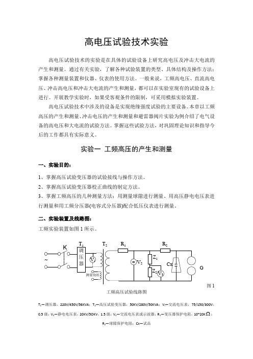
二、实验装置及线路图:工频实验装置如图1所示。
2R 1R 2G图1工频高压试验线路图T 1—调压器,220V/450V/56KVA ;T 2—高压试验变压器,50KV/280V/50KVA ;V l —交流电压表,75/150/300V ,0.5级;V 2—静电电压表,20KV/5OKV ,1.5级;V 3—交流电压表或示波器;R 1—变压器保护电阻,10~20K ;R 2—球隙保护电阻;Cx —试品三、实验说明工频高电压试验装置通常由调压器、试验变压器、保护电阻、分压器和静电电压表以及球隙等组成。
试验变压器的工作原理与电力变压器相同,但由于工作条件和工作任务的不同,试验变压器具有工作电压高、变比大、漏抗大、绝缘裕度小、容量小、工作时间短等特点。
其主要类型有单套管金属外壳型试验变压器、双套管金属外壳型试验变压器、绝缘外壳型试验变压器和串级试验变压器。
进行工频高电压试验时,要求试验电压从零开始,均匀升压,因此必须使用调压设备。
TE1501 数字式接地电阻测试仪 说明书

TE1501数字式接地电阻测试仪说明书武汉特试特科技有限公司地址:武汉市东湖高新技术开发区关山二路 特1号国际企业中心Ⅱ-2免费服务热线:800-880 0780电话:(027)6784 5315、6784 5317 传真:(027)6784 5319网址:E-Mail:TESTER@公司还备有下列仪器,敬请垂询:1、TE2011抗干扰氧化锌避雷器测试仪2、TE2000抗干扰介质损耗测试仪3、TE200/TE100高精度回路电阻测试仪4、TE150/TE500充电式测试仪表电源5、TE2030高压开关动特性测试仪6、TE6100便携式继电保护测试仪7、TE-ZC3直流电阻快速测试仪8、TE-BC2变比组别自动测试仪9、TE-HG4互感器校验仪10、TE6080油耐压全自动测试仪11、JD-2地网接地电阻测试仪12、TE-EY2 PT二次压降测试仪13、系列直流高压发生器14、系列交直流高压测量装置(分压器)15、系列轻型试验变压器16、系列大电流发生器(升流器)17、系列控制箱、控制台18、系列干式变压器19、系列高压绝缘兆欧表20、系列接地电阻测量仪21、直流高压微安表22、放电球隙尊敬的用户:在您使用本仪表之前,请仔细阅读说明书!一、产品介绍1、仪表工作原理TE3571数字接地电阻测量仪摒充传统的人工手摇发电工作方式,采用先进的中大规模集成电路,应用DC/AC变换技术将三端钮、四端钮测量方式合并为一种机型的新型接地电阻测量仪。
工作原理为由机内DC/AC变换器将直流变为交流的低频恒流,经过辅助接地极C和被测物E组成回路,被测物上产生交流压降,经辅助接地极P送入交流放大器放大,再经过检波送入表头显示。
借助倍率开关,可得到三个不同的量限:0~2Ω,0~20Ω,0~200Ω。
2、仪表使用范围本表适用于电力、邮电、铁路、通信、矿山等部门测量各种装置的接地电阻以及测量低电阻的导体电阻值;本表还可测量土壤电阻率及地电压。
发 电 机 静 态 试 验 方 案

发电机静态调试方案1 概述1.1 根据《火电工程启动调试工作规定》为明确整个试验项目及过程编制本方案,本方案主要阐述了发电机静态试验的工作内容、试验项目、工作分工、执行标准以及试验过程中应注意的安全事项。
1.2 通过对发电机静态试验,检查其性能是否符合标准要求,保证设备安全可靠投入运行。
2 试验依据2.1 GB50150-91《电气装置安装工程电气设备交接试验标准》2.2 《火电工程调整试运质量检验及评定标准》2.3 黑龙江省火电一公司企业标准《质量手册》2.4 黑龙江省火电一公司企业标准《职业安全健康和环境管理手册》2.5 《安全法》2.6 《电力建设安全工作规程》2.7 制造厂出厂试验报告及其它技术资料2.8 施工设计图纸3 人员资格要求和职责分工3.1 试验负责人:取得工程师及以上的职称,具有五年以上的试验工作经验,工作负责,身体健康。
3.2 试验工作人员:经安全规程考试合格的专业人员,熟悉试验工作,熟练掌握各种试验仪器的正确使用方法。
3.3试验负责人负责试验与质量检查,对试验的技术和试验设备及试品的安全负责。
3.4试验负责人在试验全过程中,对公司企业标准《质量手册》和《职业安全健康和环境管理手册》及《安全法》和《电力建设安全工作规程》的具体运行和全面执行负责。
3.5试验工作人员对使用仪器、设备的完好状态负责,对原始记录负责,保证原始记录的全面性和有效性。
4 试验的准备工作和应具备的条件4.1 和发电机有关的各专业安装全部结束,并经验收合格。
4.2 耐压试验时,要求制造厂、发电厂及安装单位派代表参加,安装单位指派有关人员配合进行。
4.3 试验用电源采用220V正式厂用电源。
4.4 试验用仪器、仪表经过校验,保证完好。
4.5 试验现场附近的电焊,桥吊等有碍试验的工作应停止。
4.6试验之前认真检查试验接线,特别是对工作接地和保护接地情况的检查,接地线采用截面不小于4mm2的多股软铜线并可靠接地。
OP100防雷过电压保护器 说明书
NP-FL100 新型线路绝缘子防雷过电压保护器一、概述随着近年来我国大规模城乡电网改造,全国越来越多的城市配电网络大量采用架空绝缘导线线路。
与此同时,绝缘线路发生雷击断线和绝缘子击穿事故的统计数量也呈不断上升趋势,并随着绝缘导线线路长度增加而急剧上升,并已成为严重威胁配电网线路安全运行的主要根源。
据不完全统计,截止2005年底,国内一些城市如北京、上海、武汉、厦门、鄂州等地共发生绝缘线路雷击断线事故约395起,并造成多起人身伤亡和巨额财产经济损失。
因此,如何妥善解决雷击断线问题,以确保架空绝缘配电网的安全运行已经成为全国配电网系统中一个迫切需要解决的重要问题。
二、架空绝缘导线断线机理绝缘导线的雷击断线特性与裸导线的情况相比有明显不同。
在直击雷或感应雷过电压作用于裸导线引起绝缘子闪络时,接续的工频短路电弧弧根在电磁力的作用下沿导线表面不断滑移,不会集中在某一点烧灼,因此不会严重烧伤导线;而绝缘导线则不同,雷电过电压引起绝缘子闪络并击穿导线绝缘层时,被击穿的绝缘层呈一针孔状,接续的工频短路电流电弧受周围绝缘的阻隔,弧根只能在针孔处燃烧,在极短的时间内导线就会被整齐地烧断。
通常在工频续流烧断导线或损坏绝缘子之前就会引起断路器动作,切断电弧。
因此,裸导线的断线故障率明显低于架空绝缘电缆。
根据上述架空绝缘导线线路雷击断线机理分析可以看出,及时切断雷电流引起的工频续流是防止架空绝缘导线线路雷击断线事故的根本方法。
目前大多采用金属氧化物避雷器,虽然金属氧化物避雷器可起到防止雷电过电压的作用,但它有如下不足:1.安装时必须剥除绝缘电缆的绝缘层,导致雨水沿绝缘层剥除点渗入,腐蚀绝缘电缆的金属导线;2.避雷器不仅长期承受工频电压作用,同时还要间歇地承受雷电过电压及工频续流的作用,容易老化,其故障很多,成本很高;3.若大的雷电流通过避雷器,会导致避雷器承受不了而损坏,引起短路接地,导致绝缘电缆断线。
三、产品简介基于上述情况我公司综合了国内外各种雷电过电压技术的利与弊。
发电机定子绕组交、直流耐压试验作业指导书
发电机定子绕组交、直流耐压试验作业指导书 1.发电机主要参数:型号:QFW-30-2 额定功率:30000kw功率因数:0.8 额定电压:10500V额定电流:2062A 频率:50HZ 额定转速:3000r/min 转子电压:196V转子电流:384A 接法:Y制造厂家:济南发电设备厂2.试验依据标准:国标GB50150—91规程和产品出厂技术要求的规定进行。
3.试验前应具备的条件和试验时的准备工作。
3.1、发电机本体具备耐压试验条件,安装工作应全部结束。
3.2、采用专用的ZC-37型水内冷发电机绝缘电阻测试仪测量定子绕组的绝缘电阻,所测量数据换算至75℃运行温度下与厂家数据比较无显著差别。
3.3、断开发电机定子绕组冷却水的进出口法兰处有机玻璃垫块两侧的金属短接连片,试验结束后复位。
3.4、试验时通入合格的冷却水,并保证水压正常,水质检验合格,无机械杂质,导电率不大于5微西/厘米,PH值等于7-8,试验中维持此水质要求,水温控制在摄氏25-30度。
3.5、进出水汇水管的对发电机本体的绝缘电阻值RH≥30ΚΩ,对定子绕组的绝缘电阻RY≥100ΚΩ。
3.6、定子绕组冷却水系统保持循环运行,进水压力保持在0.2Mpa左右,并保持水温和导电率的稳定。
3.7、准备一套直流耐压及泄漏试验设备和一套工频交流耐压试验设备,以及相应试验用仪器仪表等级不低于0.5级。
3.8、拆开发电机首尾出线端之间的伸缩节,并在母线侧短接接地,转子绕组应从滑环处可靠短接接地,相应的测温元件进行相应的处理。
3.9、试验现场清理干净,照明充足,划定警戒区,并有明确的标志,安排专人监护。
4.发电机绝缘情况判定4.1 定子绕组的绝缘电阻与厂家出厂数据换算至75℃运行温度下无显著差别,吸收比应大于1.6而且各相绝缘电阻的不平衡系数不应大于2方可进行试验。
4.2 测量绝缘时采用专用的ZC-37型水摇表进行,测试前应先将定子绕组短接接地1-2分钟后进行测量。
武汉特试特 TE系列遥控放电球隙 说明书

TE系列遥控放电球隙说 明 书武汉特试特科技有限公司地址: 武汉市东湖高新技术开发区关山二路特1号国际企业中心Ⅱ-2免费服务热线:800-880 0780电话: (027)6784 5315、6784 5317传真: (027)6784 5319网址: E-MAIL:****************一、衷心感谢您使用本公司的产品,您因此将获得本公司全面的技术支持和服务保障。
二、本使用说明书适用于T E系列遥控放电球隙。
三、当您在使用本产品前,请仔细阅读本使用说明书,并妥善保存以备查考。
四、请严格按说明书要求步骤操作,使用不当可能危及人身安全。
五、在阅读本说明书或仪器使用过程中如有疑惑,可向我公司咨询。
咨询电话:800-880 0780前言目录1、概述1.1 用途-----------------------------------11.2 性能特点--------------------------------12、特别提示2.1 电源方面--------------------------------22.2 安全方面--------------------------------22.3 操作方面--------------------------------23、技术特征3.1 名称-----------------------------------33.2 主机结构型式与尺寸 -----------------------33.3 使用电源--------------------------------33.4 使用环境要求-----------------------------33.5 间隙调节范围-----------------------------33.6 间隙调节精度----------------------------33.7 分辨率---------------------------------34、工作原理4.1 原理框图--------------------------------45、面板布置5.1 面板示意图------------------------------55.2 各部件说明------------------------------55.3 按键说明--------------------------------55.4 遥控按键说明----------------------------56、页面说明6.1 开机页面--------------------------------66.2 主菜单----------------------------------76.2.1 自动调节间隙---------------------------76.2.2 结束试验、归位-------------------------86.2.3 帮助页-------------------------------87、基本操作7.1如何更换保险丝---------------------------98、试验8.1 接线准备--------------------------------108.2 试验步骤--------------------------------108.3 试验结束后现场清理------------------------10目录9、接线图 ----------------------------------1110、运输与保养 ------------------------------1211、随机配件 ----------------------------- 1312、售后服务 ----------------------------- 141.1 用途T E系列遥控放电球隙适用于交直流高压试验时的高压测量及保护被试品。
放电球隙测压器原理及使用标准

放电球隙测压器原理及使用标准1.FDB 放电球隙测压器(水平式)其结构有:活动底座,绝缘支管,铜球,调节轴,坚固螺钉,微调轴(标尺),微调轮,水电阻等主要部件组成。
2.FDB 球隙器的应用:在做试验时将球隙器和试品并联,球隙器本身串有每伏1欧的保护电阻,先将球隙调整在60%试验电压(球隙的放电距离可以从下面球隙放电电压表:表1,表2中查得),此时试品应同时接上测定。
当球隙放电时,记录试验变压器的低压测电压表读数(取3-4次平均值),然后按同样方式测定70%和80%试验电压时电压表读数,以次三点线值作一曲线(大多为一直线),再延长此曲线(大多为按正比例推算)至所需的试验电压值,求得低压测电压表的读数,然后将球隙调整至比试验电压高10-15%位置上。
作为耐压试验过程中可能发生电压的放电保护。
当大气条件与标准情况不同时由下表得数值进行校正,应将此数值乘以校正系数K,校正系数K 直接由空气相对密度δ决定决定,它们间的关系如下表所列。
空气相对密度δ按下式计算δ=.1013b t ++27320273=0.289tb+273式中:b-表示大气压力mba r t--表示摄氏度℃δ=t b ++27320273.760=0.386tb+273上式中b 为以毫米水银柱表示的大气压力,t 表示摄氏温度空气相对密度δ与校正系数K 的关系空气相对密度δ0.700.750.800.850.900.95 1.00 1.05 1.10 1.15校正系数0.720.770.820.860.910.95 1.00 1.05 1.09 1.13当δ值在0.95和1.05之间时,则校正系数等于空气相对密度.三、注意事项高电压绝缘试验的安全正确,必须按照国家1685-10-01实施GB311.6-83《高电压试验技术第二部分试验程序》和水电部《电气设备预防性试验规程》为准。
表1一球接地的球隙使用于交流电压,负极性的雷电冲击电压和长波尾冲击及两种性的直流电压KV(峰值)。
电流控制器说明书jdl104

电流控制器说明书jdl104jdl104冲击电流发生器控制系统是专为冲击大电流发生器试验装置而设计的智能化控制系统,它在技术上采用了可编程控制器技术,几乎所有的控制功能均由软件实现,因而极大地简化了系统组成,大大提高了系统的可靠性。
此外它还采用光纤传输测控信息,这在高电压、大电流试验中也极大地增强了系统的安全性,避免设备可能遭受高压放电瞬态过程的危害。
独特的触摸屏操作界面具有良好的人机对话功能,操作过程方便简单,具有智能化的特点。
系统特点:1、采用PLC可编程控制器技术,使控制系统实现超小型化及高可靠性能,并很方便与计算机连接可达到计算机智能自动控制。
2、控制操作台与控制箱采用光纤连接,替代传统使用的多芯控制电缆,使得控制器与冲击发生器没有电联系,从根本上解决高压试验地电位抬高对测控系统的影响,使系统更加简便、安全、耐用。
3、关键器件及面板全部采用优质进口器件,质量可靠、外观豪华、操作自如。
4、操作界面采用液晶触摸屏,可灵活编程并进行控制软件升级。
界面具有画面提示功能,可实现人机对话,操作方便,不易出错。
5、具有控制、测量、保护、连锁等各种功能,并可实现自动控制、程序控制,功能可拓展。
•系统构成jdl104冲击电流发生器控制系统是由PLC控制箱、控制操作器和光纤传输线系统三部分组成。
控制操作器通过PLC控制箱来控制冲击电流发生器试验系统的全部操作。
控制操作器与PLC控制箱之间使用了两芯光纤传输控制命令及反馈工作状态,这使得控制系统具有很好的抗干扰性能,并避免了地电位抬高等因素可能造成的设备损坏。
由于取消了笨重的多芯控制电缆,控制操作器的使用也更加方便灵活。
它既可以单独放置在桌面上使用,也可以作为控制台的一个插件与其他单元配合使用。
jdl104冲击电流发生器控制系统的构成如下图所示,三、功能介绍jdl104冲击电流发生器控制系统选用不同的子画面进行控制操作。
计算机单元可用于系统的功能扩展、数据分析和处理。
发电机定子绕组交流耐压试验方案
#1发电机定子绕组交流耐压试验方案1.#1发电机基本参数型号:50WT21E—106额定容量:415MV A额定功率:352.75MW额定电压:20KV额定电流:11980A频率:50Hz功率因数:0.85额定转速:3000г/min冷却方式:水氢氢励磁方式:静态励磁试验目的本次试验属于大修前试验,目的是判断发电机定子绕组绝缘水平,检查是否存在绝缘缺陷。
试验依据GB755—2000(《旋转电机定额和性能》)GB/T7064—2002(《透平型同步电机技术要求》)制造厂说明书试验条件办理发电机工作票,同时其他专业工作票交回。
发电机气体置换已经结束,转子在定子膛内。
发电机内冷水正常投运,水电导率符合运行标准,但尽可能低。
发电机绝缘电阻试验合格。
所有温度卡件拔出,测点等元件应短路接地,以防试验中损坏。
试验前要测试发电机电容量,核对补偿电感。
将发电机转子及封母接地,电流互感器短路接地。
球隙放电电压调整合格,保护水阻选用适当。
解除电源开关的漏电保护。
试验方法试验接线图如图1所示。
考虑现场试验电源容量的限制,需采用电抗器(接在被试发电机侧)进行无功补偿。
选用35H、20KV的4只电抗器两串两并,并联后电抗值为35H。
根据规程要求施加电压30KV。
6.试验步骤:经检查确认被试品、绝缘电阻合格、内冷水水质符合要求后,方具备进行交流耐压试验的条件。
拆除或断开所有与被试品相连的连线,按安全规程的有关规定做好全部安全措施。
按接线图检查试验接线应正确无误,试验设备布置合理,便于操作并符合安全规程中的有关规定。
保护接地应牢固可靠。
检查试验设备及测量仪表应完好无损,放置平稳,调好零位。
检查确认无误后方可开始试验,升压从零开始,缓慢的升到规定的试验电压值,持续1分钟,并在耐压持续时间内,保持电压稳定。
时间到后缓慢降下电压。
7.安全注意事项经检查确认被试品、绝缘电阻试验已合格。
严格执行DL408—91《电业安全工作规程(发电厂和变电所电气部分)》中有关规定及现场的相关安全措施。
高电压技术第三章电气设备绝缘试验技术-资料

试品容量小,吸收比:K
R
'' 60
R
'' 15
试品容量大,吸收比:K
R
' 10
R
' 1
如绝缘良好,吸收现象显著,K>>1;
如绝缘严重受潮或有大的缺陷,K接近1。
吸收比的测量
工程上常用兆欧表(摇表)进行测量,以加压60s后的读数 为试品的绝缘电阻。 原理:兆欧表是利用流比计的原理构成。电压线圈与电 流线圈中电流在磁场中产生 两个相反的转动力矩, 在力矩差作用下,线圈带动 指针旋转,直到旋转到平衡 为止。 关系:
冲击电压发生器特性参数:
(1)额定电压 (2)冲击电压发生器的级数 (3)冲击电压发生W器' 的 12最C大0Uˆ冲m2 击能量
(4)效率
Uˆ m Um
C0
C0 C f
4.1 冲击高电压的产生(续2)
2.多级冲击电压发生器
并联充电;串联放电
4.1 冲击高电压的产生(续3)
3. 操作冲击高压的获得
tgδ是绝缘品质的重要指标,测量tgδ是判断 电气设备绝缘状态的灵敏有效的方法
tgδ能反映绝缘的整体性缺陷(全面老化)和小 容量试品中的严重局部性缺陷
tgδ随电压变化的曲线可以判断绝缘是否受潮, 含有气泡及老化的程度
大容量的设备绝缘存在局部缺陷时,应尽可能 将设备解体后分解测量进行分析
短路时
摇动手柄,有 IA 和IV,IA最大,其转动力矩远大于Iv产 生的力矩,使指针顺时针偏转最大位置,指针指向0, 即被测绝缘电阻为0
测量绝缘电阻能有效地发现下列缺陷:
(1)总体绝缘质量欠佳; (2)绝缘受潮 (3)两极间有贯穿性的导电通道; (4)绝缘表面情况不良。
Cooper Power Series 电流限制放电断流保护管安装说明说明书
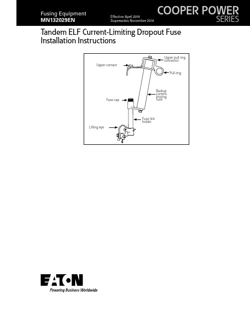
Tandem ELF Current-Limiting Dropout FuseInstallation InstructionsDISCLAIMER OF WARRANTIES AND LIMITATION OF LIABILITYThe information, recommendations, descriptions and safety notations in this document are based on Eaton Corporation’s (“Eaton”) experience and judgment and may not cover all contingencies. If further information is required, an Eaton sales office should be consulted. Sale of the product shown in this literature is subject to the terms and conditions outlined in appropriate Eaton selling policies or other contractual agreement between Eaton and the purchaser.THERE ARE NO UNDERSTANDINGS, AGREEMENTS, WARRANTIES, EXPRESSED OR IMPLIED, INCLUDING WARRANTIES OF FITNESS FOR A PARTICULAR PURPOSE OR MERCHANTABILITY, OTHER THAN THOSE SPECIFICALL Y SET OUT IN ANY EXISTING CONTRACT BETWEEN THE PARTIES. ANY SUCH CONTRACT STATES THE ENTIRE OBLIGATION OF EATON. THE CONTENTS OF THIS DOCUMENT SHALL NOT BECOME PART OF OR MODIFY ANY CONTRACT BETWEEN THE PARTIES. In no event will Eaton be responsible to the purchaser or user in contract, in tort (including negligence), strict liability or other-wise for any special, indirect, incidental or consequential damage or loss whatsoever, including but not limited to damage or loss of use of equipment, plant or power system, cost of capital, loss of power, additional expenses in the use of existing power facilities, or claims against the purchaser or user by its customers resulting from the use of the information, recommendations and descriptions contained herein. The information contained in this manual is subject to changewithout notice.iiINSTALLATION INSTRUCTIONS MN132029EN April 2019ContentsDISCLAIMER OF WARRANTIES AND LIMITATION OF LIABILITY . . . . . . . . . . . . . . . . . . . . . . . . . . . . . . . . . . .II SAFETY FOR LIFE . . . . . . . . . . . . . . . . . . . . . . . . . . . . . . . . . . . . . . . . . . . . . . . . . . . . . . . . . . . . . . . . . . . . . . . . .IV SAFETY INFORMATION . . . . . . . . . . . . . . . . . . . . . . . . . . . . . . . . . . . . . . . . . . . . . . . . . . . . . . . . . . . . . . . . . . . .IV Safety Instructions (iv)PRODUCT INFORMATION . . . . . . . . . . . . . . . . . . . . . . . . . . . . . . . . . . . . . . . . . . . . . . . . . . . . . . . . . . . . . . . . . . .1 Introduction (1)Acceptance and initial inspection (1)Handling and storage (2)Standards (2)APPLICATION . . . . . . . . . . . . . . . . . . . . . . . . . . . . . . . . . . . . . . . . . . . . . . . . . . . . . . . . . . . . . . . . . . . . . . . . . . . . .2 INSTALLING A FUSE LINK IN FUSE LINK HOLDER . . . . . . . . . . . . . . . . . . . . . . . . . . . . . . . . . . . . . . . . . . . . . .3 INSTALLING A TANDEM ELF FUSE IN CUTOUT . . . . . . . . . . . . . . . . . . . . . . . . . . . . . . . . . . . . . . . . . . . . . . . . .3 OPERATION AND REFUSING . . . . . . . . . . . . . . . . . . . . . . . . . . . . . . . . . . . . . . . . . . . . . . . . . . . . . . . . . . . . . . . .4 Removal of the tandem ELF fuse (4)Testing of the backup current-limiting fuse (4)Refusing the backup current-limiting fuse (5)Refusing the Fuse Link in Fuse Link Holder (5)MAINTENANCE . . . . . . . . . . . . . . . . . . . . . . . . . . . . . . . . . . . . . . . . . . . . . . . . . . . . . . . . . . . . . . . . . . . . . . . . . . .5 iii INSTALLATION INSTRUCTIONS MN132029EN April 2019Safety for lifeEaton meets or exceeds all applicable industry standards relating to product safety in its Cooper Power™ series products. We actively promote safe practices in the use and maintenance of our products through our service literature, instructional training programs, and the continuous efforts of all Eaton employees involved in product design, manufacture, marketing, and service.We strongly urge that you always follow all locally-approved safety procedures and safety instructions when working around high-voltage lines and equipment, and support our “Safety For Life” mission.Safety informationThe instructions in this manual are not intended as a substitute for proper training or adequate experience in the safe operation of the equipment described. Only competent technicians who are familiar with this equipment should install, operate, and service it.A competent technician has these qualifications:●●Is thoroughly familiar with these instructions.●●Is trained in industry-accepted high- and low-voltage safe operating practices and procedures.●●Is trained and authorized to energize, de-energize, clear, and ground power distribution equipment.●●Is trained in the care and use of protective equipment such as arc flash clothing, safety glasses, face shield, hard hat, rubber gloves, clampstick, hotstick, etc. Following is important safety information. For safe installation and operation of this equipment, be sure to read and understand all cautions and warnings.This manual may contain four types of hazard statements:Indicates an imminently hazardous situation which, ifnot avoided, will result in death or serious injury . Indicates a potentially hazardous situation which, if notavoided, could result in death or serious injury .Indicates a potentially hazardous situation which, if not avoided, may result in minor or moderate injury .NOTICEIndicates a potentially hazardous situation which, if not avoided, may result in equipment damage only .Safety instructionsFollowing are general caution and warning statements that apply to this equipment. Additional statements, related to specific tasks and procedures, are located throughout themanual.Hazardous voltage . Contact with hazardous voltage will cause death or severe personal injury . Follow all locally-approved safety procedures when working around high- and low-voltage lines and equipment .G103 .3Before installing, operating, maintaining, or testing this equipment, carefully read and understand the contents of this manual . Improper operation, handling, or maintenance can result in death, severe personal injury, and equipment damage .G101 .0This equipment is not intended to protect humanlife . Follow all locally-approved procedures and safety practices when installing or operating this equipment . Failure to comply can result in death, severe personal injury, and equipment damage .G102 .1Power distribution and transmission equipment must be properly selected for the intended application . It must be installed and serviced by competent personnel who have been trained and understand proper safety procedures . These instructions are written for such personnel and are not a substitute for adequate training and experience in safety procedures . Failure to properly select, install, or maintain power distribution and transmission equipment can result in death, severe personal injury, and equipment damage . G122 .2iv INSTALLATION INSTRUCTIONS MN132029EN April 20191Tandem ELF current-limiting dropout fuse installation instructionsINSTALLATION INSTRUCTIONSMN132029EN April 2019Eaton’s Cooper Power series T andem ELF Fuse is designed to be installed in accordance with normal safe operating procedures . These instructions are not intended to supersede or replace existing safety and operating procedures . Read all the instructions before installing the T andem ELF Fuse . The T andem ELF Fuse should be installed and serviced only by personnel familiar with good safety practice and the handling of high-voltage electrical equipment .Product informationIntroductionEaton’s Cooper Power series Tandem ELF current-limiting fuse is designed for transformer protection. The Tandem ELF fuse can be applied for fusing single-phase transformers and for fusing three-phase transformers (or three-phasebanks of single-phase transformers). This fuse combines the features of a series fuse link and a backup current-limiting fuse in one package. The Tandem ELF fuse (refer to Figure 1) features a unique design for fast replacement of the fuse link after a low fault current operation or excessive transformer overload current or replacement of both the fuse link and backup current-limiting fuse after a high fault current operation. Note that when using recommended fuse links or other properly coordinated fuse links, the fuse link will operate to provide for the dropout action of the Tandem ELF fuse following an interruption.Read this manual firstRead and understand the contents of this manual and follow all locally approved procedures and safety practices before installing or operating this equipmentAdditional informationThese instructions cannot cover all details or variations in the equipment, procedures, or process described nor provide directions for meeting every possible contingency during installation, operation, or maintenance. When additional information is desired to satisfy a problem not covered sufficiently for the user’s purpose, contact your Eaton representative.Figure 1 . T andem ELF fuse assemblyAcceptance and initial inspectionEach Tandem ELF fuse is completely inspected and tested at the factory. It is in good condition when accepted by the carrier for shipment. Upon receipt of the Tandem ELF fuse, inspect the connector thoroughly for damage and loss of parts incurred during shipment. If damage or loss is discovered, file a claim with the carrier immediately.T able 1 . Recommended ELF current-limiting dropout fuse voltage ratingsCoordinates with fuse links up throughBackup current-Limiting fuse Edison type D Kearney type X Kearney type QA NEMA type K Kearney Type 200 Edison type N NEMA type T Edison type H Kearney type KS 25 K20103025203015872Tandem ELF current-limiting dropout fuse installation instructionsINSTALLATION INSTRUCTIONS MN132029EN April 2019Handling and storageIf the Tandem ELF fuse is to be stored for an appreciable time before installation, provide a clean, dry storage area. Locate the Tandem ELF fuse so as to minimize the possibility of physical damage.Quality StandardsISO 9001-Certified Quality Management SystemApplicationWhen selecting the proper size Tandem ELF fuse for each installation; transformer current, system voltage, and upstream coordination should be taken into account.The Tandem ELF fuse uses the 25 K Companion II backup current-limiting fuse. This Companion II fuse rating indicates the largest Type K-rated fuse link that properly coordinates with the fuse. The highest current ratings for other fuse link types that will properly coordinate with the Tandem ELF backup current-limiting fuse are shown in Table 1.The voltage ratings recommended for the Tandem ELF fuse on most commonly encountered distribution systems are listed in Table 2.For further information concerning the coordination of the Tandem ELF fuse see Eaton’s Cooper Power series catalog section CA132028EN or contact your Eaton representative.Installation procedureThe Tandem ELF fuse is shipped only with the backup current-limiting fuse installed. Remove the fuse link (if supplied and of the proper rating) from the package andinstall into Tandem ELF fuse following the instructions below:otee:N If the fuse link is not supplied, select the correct fuselink ampere size based on the application section in catalog section CA132028EN and with the current rating for the respective fuse link type selected not to exceed the values shown in Table 1 of these instructions.T able 2 . T andem ELF Fuse Voltage ApplicationSystem voltage (kV)Recommended Tandem ELF fuseVoltage class rating (kV)Nominal Maximum WyeDelta 2.4 2.54–152.4/4.16 2.54/4.415–4.16 4.4–154.8 5.1–154.8/8.32 5.1/8.815–6.97.26–156.93/12.07.3/12.715–7.27.62–157.2/12.477.62/13.215–7.628.1–157.62/13.28.1/14.015–7.978.4–157.97/13.88.4/14.515–8.328.8–158.32/14.48.8/15.215–12/20.812.7/22.027–12.4713.2–15*13.2/22.914/24.227–13.213.9–15*13.814.5–15*14.4/24.915.2/26.427–14.415.2–15*19.94/34.5421.1/36.527–23.024.3–27** F or single-phase applications on delta systems, one Tandem ELF fuse of this rating is required in each phase.Figure 2 . T andem ELF fuse link holder assembly3Tandem ELF current-limiting dropout fuse installation instructionsINSTALLATION INSTRUCTIONS MN132029EN April 2019Installing a fuse link in fuse link holder1. Remove the fuse cap from the middle connector ofthe fuse link holder assembly. See Figure 2.2. Insert the fuse link, cable end first, into the top ofthe fuse link holder and pull out at the lower end or in accordance with the fuse link manufacturer’s instructions.3. Replace the fuse cap on the fuse link holder middleconnector and tighten with a wrench.4. Holding the lower end of the fuse link holder,depress the latch, feed the cable over the latch and around the fuse link clamping nut in a clockwise direction to prevent strand breakage when the clamping nut is tightened . See Figure 3.5. While maintaining tension of the fuse link cable,tighten the fuse link clamping nut with a wrench .6. Cut excess fuse link cable .otee:N Never insert excess leader into fuse link holder tube.lifting eye.2. Place the Tandem ELF fuse into the hinge of the cutout.See Figure 4.When using the T andem ELF fuse in the cutout, hot gasses and high velocity particles are expelled from fuseholder during interruption . This expulsion could cause serious injury .The T andem ELF fuse should not be installed if it has any visual signs of operation and/or damage .3. Remove the hook stick.4. Take a position well clear of the vented end andexhaust path of the cutout in the closed position andFigure 5 . Closing the T andem ELF fuse into the interchangeable cutout4Tandem ELF current-limiting dropout fuse installation instructionsINSTALLATION INSTRUCTIONSMN132029EN April 2019Do not attempt to interrupt load current by pulling on the T andem ELF fuse pull ring to open the cutout . An arc started by opening a cutout under load in this manner could cause injury or damage to equipment .otee:N Interchangeable cutouts are equipped with hooksfor use with a loadbreak tool. To open the Tandem ELF fuse from the cutout, use ONL Y an approved loadbreak tool designed for use with cutouts and follow the instructions provided with such tool.Operation and refusingOnly qualified personnel should operate a cutout . Such personnel should always wear appropriate protective equipment such as rubber gloves, hard hats, safety glasses, etc ., in accordance with established utility andsafety practices .A T andem ELF fuse open in a cutout indicates a blown fuse due to an overload or fault condition . Faults and/or visibly failed equipment should be located and repaired before refusing a T andem ELF fuse .When the Tandem ELF fuse (refer to Figure 6) operates, the fuse will drop open in the cutout.Removal of the tandem ELF fuse1. Insert a hook stick into the lifting eye of the T andemELF fuse and remove it from the hinge of the cutout .If the T andem ELF fuse operates for a high current fault, the backup current-limiting fuse may be hot enough to cause burns . Wear gloves and handle the T andem ELF fuse by the fuse link holder to avoid burns .Testing of the backup current-limiting fuseThe backup current-limiting fuse should always be tested after an operation of the Tandem ELF fuse.1. Perform a continuity check on the backupcurrent-limiting fuse as shown in Figure 7.Failure to check the T andem ELF’s backup current-limiting fuse may result in placing an operated/damaged fuse back in service . This could result in personal injury, fire, or equipment damage .2. If the backup current-limiting fuse does not havecontinuity, change out the fuses as described in “Refusing the Backup Current-Limiting Fuse” on page 6. If the fuse does have continuity, skip to“Refusing Fuse Link in Fuse Link Holder” on page 6.Figure 6 . T andem ELF fuse in T ype L cutout after operation5Tandem ELF current-limiting dropout fuse installation instructionsINSTALLATION INSTRUCTIONS MN132029EN April 2019Refusing the backup current-limiting fuse1. Remove the backup current-limiting fuse byunbolting it from the middle connector .2. Unbolt the upper pull ring connector from thebackup current-limiting fuse and replace with a new backup current-limiting fuse . Bolt the reused upper pull ring connector to the new backup current-limiting fuse noting proper engagement of the alignment key. See Figure 8.3. Bolt the backup current-limiting fuse to the middleconnector noting proper engagement of the alignment key as shown in Figure 8 .Refusing the fuse link in fuse link holder1. Remove the fuse cap and then the operated fuselink from the fuse link holder of the T andem ELF fuse . 2. Visually inspect the fuse link holder bore andremove any debris .3. Continue with the steps outlined in “Installing aFuse Link in Fuse Link Holder” on page 2.MaintenanceRefer to ANSI Standards (C37.48) as a general guide for maintenance of the cutout.1. Periodically inspect the fuse link at the lower end ofthe fuse link holder for evidence of corrosion .2. Replace fuse links which show signs ofdeterioration (broken strands, heavy corrosion, etc).3. Replace broken or cracked porcelain and clean orreplace if heavily contaminated .4. Inspect contacts for excessive pitting or burningand replace as necessary .5. Check the fuse link holder fiber liner for cracking orexcessive erosion . If cracked or if the I.D. is larger than 0.45”, then replace the fuse link holder.6. If the fuse link holder shows any signs of electrical tracking it should be replaced .Figure 7 . T esting/refusing the backup current-limiting fuseFigure 8 . Refusing the backup current-limiting fuse6Tandem ELF current-limiting dropout fuse installation instructionsINSTALLATION INSTRUCTIONS MN132029EN April 2019This page is intentionally left blank.7Tandem ELF current-limiting dropout fuse installation instructionsINSTALLATION INSTRUCTIONS MN132029EN April 2019This page is intentionally left blank.Eaton1000 Eaton Boulevard Cleveland, OH 44122United StatesEaton’s Power Systems Division 2300 Badger Drive Waukesha, WI 53188United States/cooperpowerseries© 2019 EatonAll Rights ReservedPrinted in USAPublication No. MN132029EN / Rev. 1 April 2019Eaton is a registered trademark.All trademarks are propertyof their respective owners.For Eaton‘s Cooper Power series productinformation, call 1-877-277-4636 or visit:/cooperpowerseries.。
- 1、下载文档前请自行甄别文档内容的完整性,平台不提供额外的编辑、内容补充、找答案等附加服务。
- 2、"仅部分预览"的文档,不可在线预览部分如存在完整性等问题,可反馈申请退款(可完整预览的文档不适用该条件!)。
- 3、如文档侵犯您的权益,请联系客服反馈,我们会尽快为您处理(人工客服工作时间:9:00-18:30)。
放电保护球隙说明书
由于输入输出端子、测试柱等均有可能带电压,在插拔测试线、电源插座时,会产生电火花,小心电击,
避免触电危险,注意人身安全!
安全要求
请阅读下列安全注意事项,以免人身伤害,为了避免可能发生的危险,只可在规定的范围内使用。
只有合格的技术人员才可执行维修。
—防止火灾或人身伤害
使用适当的电源线。
只可使用专用并且符合规格的电源线。
正确地连接和断开。
当测试导线与带电端子连接时,请勿随意连接或断开测试导线。
注意所有终端的额定值。
为了防止火灾或电击危险,请注意所有额定值和标记。
在进行连接之前,请阅读使用说明书,以便进一步了解有关额定值的信息。
使用适当的保险丝。
只可使用符合规定类型和额定值的保险丝。
请勿在潮湿环境下操作。
请勿在易爆环境中操作。
-安全术语
警告:警告字句指出可能造成人身伤亡的状况或做法。
目录
一、主要特点----------------------------5
二、技术指标----------------------------5
三、注意事项----------------------------6
一.主要特点
放电球隙测压器,是一对直径相同的球型电极,当其与高压试验变压器,控制台,调压器,水电阻等组成成套测试设备后,可在工频高压试验时用于高压测量及保护被试物品之用。
高压成套设备
成套试验设备(包括高压试验变压器,控制台,调压器,以及球隙器,水电阻和被试物)装配连结示意图。
二.技术指标
1.放电球隙测压器(水平式)其结构有:活动底座,绝缘支管,铜球,调节轴,坚固螺钉,微调轴(标尺),微调轮,水电阻等主要部件组成。
2.球隙器的应用:在做试验时将球隙器和试品并联,球隙器本身串有每伏1欧的保护电阻,先将球隙调整在60%试验电压(球隙
= 0.289t +273
式中:b-表示大气压力 mba r
t- -表示摄氏度℃
δ= t b ++27320273.760 =0.386t b
+273
上式中b 为以毫米水银柱表示的大气压力,t 表示摄氏温度空气
相对密度δ与校正系数K的关系
当δ值在0.95和1.05之间时,则校正系数等于空气相对密度. 三.注意事项
高电压绝缘试验的安全正确,必须按照国家1685-10-01实施GB311.6-83《高电压试验技术第二部分试验程序》和水电部《电气设备预防性试验规程》为准。
表1 一球接地的球隙使用于交流电压,负极性的雷电冲击电压和长波尾冲击及两种性的直流电压KV(峰值)
表2 一球接地的球隙使用于正极性的雷电冲击电压和长波尾冲击电压KV。