jperf-2.0.0使用教程
直读光谱仪软件操作规程(3篇)

第1篇直读光谱仪软件操作规程是针对直读光谱仪配套软件的操作指南,旨在指导用户正确、高效地使用软件进行光谱分析。
本规程适用于所有类型的直读光谱仪软件,包括数据采集、处理、分析及报告等功能。
二、软件安装与启动1. 确保计算机操作系统符合软件要求,并安装必要的驱动程序。
2. 将软件安装光盘放入光驱,按照提示完成安装。
3. 双击桌面上的软件图标,或通过开始菜单找到软件并启动。
4. 在软件启动过程中,如需进行系统设置,请按照提示进行操作。
三、软件界面介绍1. 菜单栏:包含文件、编辑、视图、工具、帮助等菜单项,用于执行各种操作。
2. 工具栏:提供常用功能的快捷按钮,如新建、打开、保存、打印等。
3. 工作区:显示当前操作的数据、图表等信息。
4. 状态栏:显示软件状态、当前操作等信息。
四、数据采集与处理1. 连接光谱仪:确保光谱仪与计算机连接正常,打开光谱仪电源。
2. 采集数据:在软件中选择合适的分析方法,设置相关参数,开始采集数据。
3. 数据处理:采集完成后,对数据进行平滑、滤波、提取等处理。
五、光谱分析1. 选择分析方法:根据样品成分和含量要求,选择合适的光谱分析方法。
2. 设置分析参数:根据样品特性,设置分析参数,如积分时间、扫描速度等。
3. 进行分析:点击“分析”按钮,软件将自动进行光谱分析。
4. 查看分析结果:分析完成后,在工作区显示分析结果,包括含量、标准偏差等。
六、报告生成与打印1. 生成报告:点击“报告”菜单,选择报告模板,将分析结果生成报告。
2. 打印报告:将生成的报告导出为PDF或Word格式,进行打印。
七、软件关闭1. 关闭报告:完成报告打印后,关闭报告窗口。
2. 退出软件:点击菜单栏中的“文件”菜单,选择“退出”或点击软件右上角的关闭按钮。
3. 断开光谱仪连接:关闭光谱仪电源,确保光谱仪与计算机连接正常断开。
八、注意事项1. 确保光谱仪与计算机连接正常,避免数据采集失败。
2. 在进行光谱分析时,请仔细设置分析参数,确保分析结果的准确性。
FT-IR中文操作手册(详)-2
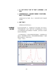
4.在“Y-轴”框中的“开始”和“结束”文本框里输入Y轴范围。
5.如果想将新设定的Y轴范围用于谱图窗口中的所有谱图,则选中“用于所有谱图”。
如果没有选中这个选框,那么Y轴的范围只适用于被选择的谱图。
6.选择“确定”。
谱图按设定的范围来显示。
自动满刻度无论何时使用选择工具、查看箭头或“滚动/缩放”窗口来显示显示谱图不同的谱图区域,“显示”菜单中的“自动满刻度显示”命令将会自动满刻度显示活动谱图窗口中的谱图。
这将有助于以满刻度的形式观察谱图。
“自动满刻度显示”将每张谱图的最高数据点(或谱图标注的最高点)移到谱图区的顶部,将每张谱图的最低数据点(或谱图标注的最低点)移到X轴上。
下面是一个例子:如果谱图的标注也被显示,那么当谱图纵坐标调整时,标注仍能显示出来。
备注如果需要调整谱图显示,而不希望谱图以满刻度形式显示,那么关闭“自动满刻度显示”即可。
▲如何操作自动满刻度显示谱图在“显示”菜单中选择“自动满刻度显示”命令。
此命令选中后,在命令名旁边出现一个“√”记号。
只要命令是打开的,则使用选择工具或取景器时,窗口中的谱图将以满刻度形式显示。
若“√”记号存在时要关闭这个命令,在“显示”菜单中再选择“自动满刻度显示”命令即可,同时记号消失。
滚动和缩放谱图“显示”菜单中的“滚动/缩放”命令可以利用一套符号来调节窗口中谱图的显示,这些符号位于“滚动/缩放”窗口中。
标记有“X”的一组符号用于调整谱图的X轴范围的显示;同样标记有“Y”的一组符号用于调整谱图的Y轴范围的显示。
下表说明了这些符号各自的作用。
如果愿意,可以按下表使用计算机数字键盘上的数字键及其组合来完成这些功能。
键盘上的“NumLock”(数码锁定)功能必须是“关闭”的,同时“滚动/缩放”窗口必需显示出来,才能使用这些键。
“滚动/缩放”窗口显示时,“数码锁定”功能会自动关闭。
符号对谱图显示的作用键使所有的谱图左移(观察谱图右侧的区域)。
它与取 4景器下半部的将取景器向右滚动的滚动键作用相同。
蓝芬R2低功耗RF生态系统入门指南说明书
BlueNRG-2 Getting StartedMohit ARORALow-power RF ecosystem 2Graphical UI RF chipsetMOTION SW VOICE SW libraries librariesBLUENRG-MESH TRIPLE SDKBLE SDKAndroid SDK iOS SDKBlueNRG/Spirit RF Power SimulatorSW development PROTOCOLS / SW IP iOS/Android SDK RF modulesEvaluation Kit and Development ToolsCovered in this Presentation#Hardware Requirements #Install SDK and tools##Install Keil and License #Test Debugger connection #Compilation and debug testwith Keil#Install Mobile apps#Test BlueNRG-GUIconnectivityRun BLE Chat ExampleHardware RequirementsBlueNRG-2 Target board withUART/VCOM ST-Link V2 or STNucleo BoardSmart Phone with BLE4.2 or higher withrequired apps installedYour windows 7/10 PCSetup with all requiredsoftware and setupsInstall ST SoftwareBlueNRG-2 SDK•Standard SDK for BlueNRG-1 and BlueNRG-2 devices from ST•Contains basic tools like Navigator, Radio Init Wizard•Download and Install BlueNRG-2 SDK from link below(STSW-BLUENRG1-DK) https:///content/st_com/en/products/embedded-software/evaluation-tool-software/stsw-bluenrg1-dk.html•Installation of the package creates three directories •Installation Directory•C:\Program Files (x86)\STMicroelectronics\BlueNRG-1_2 DK 3.X.X•Contains compiled binary files, doxygen documentation, drivers and installed applications•Example Projects Path•C:\Users\XXXXX\ST\BlueNRG-1_2 DK 3.X.X•Contains the example projects for BLE, prop radio and peripheral examples•Utility launch directory•C:\ProgramData\Microsoft\Windows\Start Menu\Programs\ST BlueNRG-1_2 DK 3.X.X •Shortcuts to Release folder, Navigator and Radio Init WizardSTSW-BLUENRG1-DK post InstallB L E E x a m p l e sP e r i p h e r a l E x a m p l e sSTSW-BLUENRG1-DK ExamplesInstall ST Tools•Install BlueNRG-GUI (STSW-BNRGUI)https:///content/st_com/en/products/embedded-software/wireless-connectivity-software/stsw-bnrg1stlink.html•Install BlueNRG ST-Link Utility (STSW-BNRG1STLINK)https:///content/st_com/en/products/embedded-software/wireless-connectivity-software/stsw-bnrg1stlink.html•Install BlueNRG-X Flasher (STSW-BNRGFLASHER)https:///content/st_com/en/products/embedded-software/wireless-connectivity-software/stsw-bnrgflasher.html•Install BlueNRG current consumption estimation tool(STSW-BNRG001) https:///en/embedded-software/stsw-bnrg001.htmlUpdate ST-LINK firmware STSW-LINK007and USB driver as required STSW-LINK009Supported HardwareSTEVAL-IDB007VxBlueNRG-1 (32QFN)STEVAL-IDB008Vx BlueNRG-2 (32QFN)STEVAL-IDB009Vx BlueNRG-2 (48QFN)STEVAL-IDB008V1M BlueNRG-M2 ModuleSTEVAL-FKI001V1BlueNRG-1 + S2LPQuickly Run the BLE_Chat Example•We will use BlueNRG-2 Navigator to quickly run the example•This software is installed as part of STSW-BLUENRG1-DK•You would need a STEVAL-IDB008x board to use it•Supports direct flash write of example codes on STEVAL with UART Bootloader BlueNRG-2 NavigatorBlueNRG-2 Navigator: Hardware SetupMicro USB CableSTEVAL-IDB008VxPC running BlueNRG-2 Navigator•Open BlueNRG-2 Navigator •Navigate to BLE_Chat•BLE demo and test apps•BLE_Chat•Server•If drivers installed and board connected The Eval board pic will appear•Click on Flash and Run button Run BLE_Chat using NavigatorSTSW-BlueNRG1-DK (4/7)•The board will be flashed with the BLE_Chat Server configuration compiled code •After flashing, serial terminal would automatically appear.•Push the reset button and messages from board should display•Install a generic BLE service discovery tool like B-BLE or BLE Scanner on you phone•Enable Bluetooth and location on your phone and startthe application•Click on “Scan” button•The devices available should appear•Click on CONNECT button against “Chat_1_2”Scan and•After you connect, the servicediscovery will start•You would see three services•Generic Attribute (GATT 0x1800)•Generic Access(GAP 0x1801)•Custom Service (ST Chat Service)•Click on custom service•Then enable notifications by clickingon “N” Button. It would turn greenEnableNotification•Click on “W” button•A window will appear•Type in text (ASCII) any data tobe send to the UART•The click on “OK”Note:If size exceeds 20 bytes, BLE scannerautomatically breaks data in 20 bytes and sendacross multiple packetsThis limit can be increased to 240 bytes perpacket but depends on support of phone for “DataLength Extension (DLE)” featureExchange data from phone to UART•Type data on the Serial terminal•Hit enter key or send “\n” new linecharacter•The data will be sent to phone andwill be visible if “N” notification buttonis greenNote:if size exceeds 20 bytes, BlueNRG-2 willautomatically break the data in packets in 20bytes and send to phoneOn the phone, only last packet will display asprevious packets were received and overwrittenIf phone supports DLE, the code can request toincrease packet sizeExchange data from UART to PhoneSetup Keil IDEInstall Keil•Kindly refer below link for all details on ST version of Keil•https:///stmicroelectronics-stm32/mdk•Download Keil MDK-ARM v5 from https:///demo/eval/arm.htm•Run the downloaded MDK5xx.exe installer.•Install to any path you like. If you have existing MDK-ARM installations that you want to keep, select a new folder for MDK v5.1.Open Keil window, Click on the Pack Installer button and open it2.Select device and Click Install to download and install the Device Function packs for BlueNRG-1 and BlueNRG-2Install Keil Device Function Packs12Get Keil ST License•Follow instructions on the page link below to install the license after you install Keil •https:///stmicroelectronics-stm32/mdk•Login with an account that has administration rights.•Right-click the µVision icon and select Run as Administrator... from the context menu.•Open the dialog File —License Management... and select the Single-User License tab.•Click the button Get LIC via Internet..., then click the button OK to register the product. This action opens the License Management page on the Keil web site.•Enter the Product Serial Number 4RMW3-A8FIW-TUBLG along with your contact information and click the button Submit.•An e-mail is sent back with the License ID Code (LIC) within a few minutes.•To activate the Software Product•enter the LIC in the field New License ID Code (LIC) of the dialog License Management (2)•click Add LIC (3)•Verify the license as visible in screenshotwith expiry dateActivate Keil ST License•After DFP and License are installed, open BLE Chat example project in Keil \\STSW-BLUETILE-DK 1.3.0\Project\BLE_Examples\BLE_Chat\MDK-ARM\BlueNRG-2•Select ST-Link as debuggerSelect ST-Link as debugger (1)•Settings for ST-Link•Click on settings (2)•Check both the download options (3)•Verify download functions (4) and programming algorithm (5)Settings in Keil12345Important DocumentsImportant Documents for Reference•BlueNRG-2 Datasheet PDF•PM0257 BLE stack v2.x programming guidelines PDF•UM2406 The BlueNRG-X Flasher SW package PDF•DT0120How to program and debug BlueNRG-1 and BlueNRG-2 devices PDF •UM2058 BlueNRG GUI SW package PDF•UM2109 BlueNRG-1 ST-LINK Utility software description PDF•AN5187 BlueNRG-1, BlueNRG-2 improving robustness PDFTest Debugger Connection•Pull DIO7 High on BlueNRG-2 Target (Automatic in STEVAL)•Connect the target to PC using VCOM/UART•Open BlueNRG-X Flasher•Select the relevant com port (ST DK)•Press Ctrl + E and execute mass erase•Click on “Read” button to verify the blank memory filled with FF •Remove the micro USB cable now.Erase the BlueNRG-2•If using Nucleo board, remove ST-LINK (CN2) jumpers •Connect the Target board with ST-Link V2•Refer the picture for connector alignment•Now, power up the target and then connect ST-Link V2•If red led is blinking: your STEVAL is in DFU mode, remove ST-LINK and then connect power. Afterwards connect ST-LINKSetup Hardware for DebugSWCLK SWDIO•Open BlueNRG-1 ST-Link Utility and Click on settings icon•Check if the ST-Link Serial number is visible•If you don’t see the ST -Link serial number, then•Try clicking on the Refresh button •Then, try re-plugging setup again with ST-Link only •If persists, update the driver of ST-LINK and firmware of ST-LINK V2•Please check you are using BlueNRG-1 ST-Link utility and Not STM32 ST-LINK utilityVerify SWD Connection•If your setup is fine, you should see similar in Target Information•If BlueNRG-2 is not visible, then you should match thesettings as per snapshot•Once you see the Target voltage and Target, you shouldclick on “OK” button•The device will now be read by debugger•If device is not detected, try to reduce the frequency andchange the modeVerify SWD TargetTest Compile and debug run of BLE_Chat project on Keil•Open BLE_Chat project in KeilPath: C:\Users\{USER NAME}\ST\BlueNRG-1_2 DK 3.2.1\Project\BLE_Examples\BLE_Chat\MDK-ARM\BlueNRG-2The project file name is “BLE_Chat” with extension “.uvprojx ”•Select the “Server” from drop down•Go to “Project” menu dropdown and click “Build Target”•The Build Output window should show as belowCompile BLE_ChatProjectEstablish Debug Session•After build, go further only if you have tested the debugger connection•Ensure that the BlueNRG-1 ST-Link utility is not connected to target•Press F8 to program the device•Press Ctrl+F5 to start the debug session•Now Open any serial monitor (tera term etc) and open the serial port•Select setting as 115200 8 N 1•Enable “\n” new line character for Enter key•Now press F5Verify Successful Debug Session Start•You will see a screen like one here if all works well•Now click on F5to run the code•You can connect via phone following procedure explained with Navigator UsageIf you face issues with Building the Project then•Goto “File” →“License Management”•The installed license should be visible as•If you don’t see above license, then refer License Installation section•If License is installed and you still face issue, check below•Keil has write permission in the drive where project is located•Try running Keil as administrator•Verify if the DFP has been installed.Help: In case of Build Error•There are different hardware available for BlueNRG-2 with combinations of•SMPS On/SMPS Off•External LF crystal/Internal RO•After opening project in Keil Go to Project →Options for Target→C/C++ (tab)•For STEVAL and BlueNRG-M2SA •LS_SOURCE=LS_SOURCE_EXTERNAL_32KHZ•SMPS_INDUCTOR=SMPS_INDUCTOR_10uH•For BlueNRG-M2SP or low-cost modules•LS_SOURCE=LS_SOURCE_INTERNAL_RO •SMPS_INDUCTOR=SMPS_INDUCTOR_NONEHelp: Verify Preprocessor SettingsHelp: Unable to establish debugPlease check below•The DFP is installed•You have configured debugger settings in Keil as per instructions•Try reading the device vis BlueNRG-1 ST-LINK utility. If you see all FF starting at address 0x10040000 then you have either•You have not flashed the right code or used an OTA configuration•your flash erase setting is set for Erase chip, change to Erase sectorsInstall Mobile Apps•Install ST BLE sensor mobile app (available for android and iOS)•Install BLE Scanner app (available for android and iOS)Install Mobile appsTest Board Connection with BlueNRG-GUI•Mount the Bluetile on the base board•Connect the Bluetile base board to PC via Micro USB cable•Check switches SW2 and SW3 on bluetile host board are on USB connector side •Open BlueNRG-X Flasher•Select the relevant com port (ST DK)•Press Ctrl + E and execute mass erase•You should see the green light on the BlueTile LED•Click on “Read” button to verify the blank memory filled with FFErase the BlueTile BoardFlash DTM Code•Click on “Select Image file” button and navigate to\\STSW-BLUETILE-DK 1.3.0\Firmware\BLE_Examples\DTM•Select file DTM_UART.hex and click on “Open”•Switch to “Image File” tab•Verify that the file starts from address 0x10040000•Now click on the “Flash” button upper section of Flasher•Once successful, you should see a popup like one below. Else, try to erase chip and change USB port and cableConnect GUI and Verify Versions•Close Flasher and Start BlueNRG-GUI•Go to “Settings”→“Set Baud Rate” and select “115200”. Then click “OK”•Select the relevant com port and click on open port button and see if the device and firmware versions are visible•If you see a message like on below, you can click “OK” and continue.Reference MaterialApplication Notes and User ManualsDoc Title HWAN4378Using the BlueNRG family transceivers under FCC title 47 part 15 in the 2400 –2483.5 MHz band BlueNRG-MS, BlueNRG-1, BlueNRG-2 AN4387Using the BlueNRG family transceivers under ETSI EN 300 328 in 2400 –2483.5 MHz band BlueNRG-MS, BlueNRG-1, BlueNRG-2 AN4392Using the BlueNRG family transceivers under ARIB STD-T66 in the 2400 –2483.5 MHz band BlueNRG-MS, BlueNRG-1, BlueNRG-2 AN4486BlueNRG, BlueNRG-MS over-the-air bootloader BlueNRG-MSAN4491BlueNRG, BlueNRG-MS updater BlueNRG-MSAN4494Bringing up the BlueNRG and BlueNRG-MS devices BlueNRG-MSAN4630PCB design guidelines for the BlueNRG and BlueNRG-MS devices BlueNRG-MSAN4818Bringing up the BlueNRG-1, BlueNRG-2 devices BlueNRG-1, BlueNRG-2AN4819PCB design guidelines for the BlueNRG-1 device BlueNRG-1AN4820BlueNRG-1 and BlueNRG-2 low power modes BlueNRG-1, BlueNRG-2AN4869BlueNRG-1, BlueNRG-2 BLE OTA (over-the-air) firmware upgrade BlueNRG-1, BlueNRG-2AN4872BlueNRG-1 and BlueNRG-2 UART bootloader protocol BlueNRG-1, BlueNRG-2AN5187The BlueNRG-1, BlueNRG-2 improving robustness BlueNRG-1, BlueNRG-2UM1770BlueNRG, BlueNRG-MS profiles application interface BlueNRG-MSUM1865BlueNRG-MS Bluetooth® LE stack application command interface (ACI)BlueNRG-MSUM1868BlueNRG and BlueNRG-MS information register (IFR)BlueNRG-MSUM2058BlueNRG GUI SW package BlueNRG-MS, BlueNRG-1UM2109BlueNRG-1 ST-LINK Utility software description BlueNRG-1UM2211BLE-Sub1GHz development kit S2-LP, BlueNRG-1, BlueNRG-2Design TipsDoc Title HWDT0049IFR configuration of BlueNRG/BlueNRG-MS using STM32ODE BlueNRG-MSDT0051Quick guide on BLE RF technology: products, evaluation kits and software packages BlueNRG-MSDT0052Quick guide on Sub-1GHz RF technology: products, evaluation kits and software packages Spirit1, SPSGRFDT0063Bluetooth Low-Energy network: time-stamping and sample-rate-conversion BlueNRG-MS, BlueNRG-1DT0068How to replace a low-speed wired connection using a BLE link BlueNRG-MS, BlueNRG-1DT0069Enabling the Bluetooth Low Energy Direct Test Mode (DTM) with BlueNRG-MS BlueNRG-MSDT0070How to set the Bluetooth device address on BlueNRG-MS BlueNRG-MSDT0074BlueNRG-MS radio stack images versions BlueNRG-MSDT0093How to mount the new balun BALF-NRG-02D3 without the top side marking BlueNRG-1, BlueNRG-2DT0107Slot allocation and multiple connection timing strategy for BlueNRG, BlueNRG-MS, BlueNRG-1 and BlueNRG-2BlueNRG-MS, BlueNRG-1, BlueNRG-2 DT0108How to program and debug BlueNRG-1 and BlueNRG-2 devices BlueNRG-1, BlueNRG-2DT0109How to configure the BlueNRG-1 and BlueNRG-2 devices in network coprocessor mode BlueNRG-1, BlueNRG-2DT0120How to program and debug BlueNRG-1 and BlueNRG-2 devices BlueNRG-1, BlueNRG-2DT0129BLE Module integration design guidelines SPBTLE-RF0, SPBTLE-RF, SPBTLE-1SNEWSoftware and Programming ManualsDoc Title HWES0280BlueNRG/BlueNRG-MS device limitations BlueNRG-MSPM0237BlueNRG, BlueNRG-MS stacks programming guidelines BlueNRG-MSPM0257BlueNRG-1, BlueNRG-2 BLE stack programming guidelines BlueNRG-1, BlueNRG-2STSW-BLEPROFILES BlueNRG-1 BLE Profiles SW package BlueNRG-1, BlueNRG-2STSW-BLUENRG-DK Setup for BlueNRG Kits BlueNRG-MSSTSW-BLUENRG1-DK BlueNRG-1, BlueNRG-2 DK SW package BlueNRG-1, BlueNRG-2STSW-BNRG001BlueNRG current consumption estimation tool BlueNRG-MS, BlueNRG-1, BlueNRG-2 STSW-BNRG1STLINK BlueNRG-1 ST-LINK utility for BlueNRG-1, BlueNRG-2 MCU BlueNRG-1, BlueNRG-2STSW-BNRGUI BLUENRG family GUI BlueNRG-MS, BlueNRG-1, BlueNRG-2 STSW-BNRG_V1-DK BlueNRG-1 DK SW package for BLE stack family v1.x BlueNRG-1STSW-BNRG-Mesh Mesh over Bluetooth Low Energy BlueNRG-MS, BlueNRG-1, BlueNRG-2 STSW-BNRG-S2LP STSW-BNRG-S2LP evaluation software package based on BlueNRG-1 and S2-LP S2-LP, BlueNRG-1, BlueNRG-2 STSW-BNRG-V71A BLE Stack Image Package Release v7.1a BlueNRG-MSSTSW-BNRG-V71C BLE Stack Image Package Release v7.1c BlueNRG-MSSTSW-BNRG-V71E BLE Stack Image Package Release v7.1e BlueNRG-MSSTSW-BNRG-V72C BlueNRG-MS BLE Stack Image Package Release v7.2c BlueNRG-MSSTSW-BNRG-V73BlueNRG-MS BLE Stack Image Package Release v7.3BlueNRG-MS•BlueNRG-1,2 Flasher utility•Supports programming via SWD and UART interface•Supports flash to be read, mass erased, written and programmed•Can connect to multiple hardware simultaneously•Autobaud and forced baud rate supported •Supports .bin and .hex formats STSW-BNRGFLASHER。
频谱分析仪的实用方法和操作流程
频谱分析仪的实用方法和操作流程英文回答:Spectrum analyzers are widely used in various fields such as telecommunications, audio engineering, and RF testing. They are essential tools for analyzing and measuring the frequency spectrum of signals. In this response, I will explain the practical methods and operating procedures of a spectrum analyzer.To begin with, the first step in using a spectrum analyzer is to connect the device to the signal source. This can be done using a coaxial cable or other appropriate connectors. Once the connection is established, the next step is to power on the spectrum analyzer and set the desired frequency range. This can be done by using the frequency control knob or entering the specific frequency range through the keypad or touchscreen.After setting the frequency range, it is important toadjust the resolution bandwidth (RBW) and video bandwidth (VBW) parameters. The RBW determines the frequencyresolution of the spectrum analyzer, while the VBW affects the displayed video output. These parameters can beadjusted based on the specific requirements of the analysis.Once the basic settings are configured, the spectrum analyzer can be used to measure and analyze the signal.This can be done by selecting the appropriate measurement mode, such as peak hold, average, or normal mode. The spectrum analyzer will then display the frequency spectrumof the signal in real-time.In addition to basic measurements, spectrum analyzers also offer advanced features such as marker functions,which allow users to measure specific frequencies or bandwidths of interest. This can be useful for identifying and analyzing specific signal components.Furthermore, spectrum analyzers often provide various display options such as logarithmic or linear scale, amplitude or power measurement, and different windowingfunctions. These options can be adjusted to enhance the visibility and accuracy of the displayed spectrum.In summary, the practical methods and operating procedures of a spectrum analyzer involve connecting the device to the signal source, setting the frequency range, adjusting the RBW and VBW parameters, selecting the measurement mode, and utilizing advanced features anddisplay options. By following these steps, users can effectively analyze and measure the frequency spectrum of signals.中文回答:频谱分析仪在电信、音频工程和射频测试等各个领域广泛应用。
IMAGing engINEs 2.0.0 图像处理工具包用户说明说明书
Package‘imagine’April27,2023Type PackageTitle IMAGing engINEs,Tools for Application of Image Filters to DataMatricesVersion2.0.0Date2023-04-19URL https:///LuisLauM/imagineBugReports https:///LuisLauM/imagine/issuesMaintainer Wencheng Lau-Medrano<*******************>Description Provides fast application of imagefilters to data matrices,using R and C++algorithms.License GPL(>=2)LazyData TRUEDepends R(>=3.1.0)Imports Rcpp,RcppArmadilloLinkingTo Rcpp,RcppArmadilloRoxygenNote7.2.3Suggests knitr,rmarkdownVignetteBuilder knitrEncoding UTF-8NeedsCompilation yesAuthor Wencheng Lau-Medrano[aut,cre]Repository CRANDate/Publication2023-04-2713:50:02UTCR topics documented:image-package (2)contextualMF (2)convolution2D (3)meanFilter (4)wbImage (5)12contextualMF Index6 image-package IMAGing engINE,Tools for application of imagefilters to data matri-cesDescriptionProvides fast application of imagefilters to data matrices,using R and C++algorithms.DetailsThis package uses C++algorithms called’engines’.More details are shown in the vignette.Author(s)Wencheng Lau-Medrano,<*******************>contextualMF Performs Contextual Median FilterDescriptionThis function performs the Contextual Median Filter(CMF)algorithm proposed by Belkin& O’Reilly(2009),based on the pseudo-code written on the paper.UsagecontextualMF(X)ArgumentsX A numeric matrix object used for applyfilters.DetailsFollowing the definition of CMF,since imagine v.2.0.0,times argument will not be available any-more.imagine offers the CMF algorithm but for the using tofind out oceanographic fronts,it is recom-mended to see and use the functions of the grec package.ValuecontextualMF returns a matrix object with the same dimensions of X.ReferencesBelkin,I.M.,&O’Reilly,J.E.(2009).An algorithm for oceanic front detection in chlorophyll and SST satellite imagery.Journal of Marine Systems,78(3),319-326(doi:10.1016/j.jmarsys.2008.11.018).convolution2D3 convolution2D Make convolution calculations from numeric matrixDescriptionThis function takes a matrix object,and for each cell multiplies its neighborhood by the kernel.Finally,it returns for each cell the mean of the kernel-weighted sum.Usageconvolution2D(X,kernel,times=1,normalize=FALSE)convolutionQuantile(X,kernel,probs,times=1,normalize=FALSE)convolutionMedian(X,kernel,times=1)ArgumentsX A numeric matrix object used for applyfilters.kernel A little matrix used as mask for each cell of X.times How many times do you want to apply thefilter?normalize logical indicating if results will(or not)be normalized.See details.probs numeric vector of probabilities with values in[0,1].DetailsConvolution is a mathematical operation which allows the multiplication of two arrays of numbers,in order to produce an array of numbers of the same dimensionality.Valid results(showed inoutput)will be only those with non-NA values,so NA holes on a matrix will expand in the order ofthe kernel size.Normalization consists on dividing the output in every window calculation by the sum(abs(as.numeric(kernel))) (disabled by default).Valueconvolution2D returns a matrix object with the same dimensions of X.convolutionQuantile uses the kernel but,for each cell,it returns the position of quantile’probs’(value between0and1).convolutionMedian is a wrapper of convolutionQuantile with probs=0.5.4meanFilterExamples#Generate example matrixnRows<-50nCols<-100myMatrix<-matrix(runif(nRows*nCols,0,100),nrow=nRows,ncol=nCols)kernel<-diag(3)#Make convolutionmyOutput1<-convolution2D(myMatrix,kernel)myOutput2<-convolutionQuantile(myMatrix,kernel,probs=0.7)#Plot resultspar(mfrow=c(2,2))image(myMatrix,zlim=c(0,100))image(myOutput1,zlim=c(0,100))image(myOutput2,zlim=c(0,100))meanFilter Make a2Dfilter calculations from numeric matrixDescriptionThis functions take a matrix object,and for each cell calculate mean,median or certain quantile around a squared/rectangular neighborhood.UsagemeanFilter(X,radius,times=1)quantileFilter(X,radius,probs,times=1)medianFilter(X,radius,times=1)ArgumentsX A numeric matrix object used for applyfilters.radius Size of squared or rectangular kernel to apply median.See Details.times How many times do you want to apply thefilter?probs numeric vector of probabilities with values in[0,1].Detailsradius must be defined as a2-length numeric vector specifying the number of rows and columns of the window which will be used to make calculations.If the length of radius is1,the window will be a square.wbImage5 Functions use C++algorithms for running some statistical calculations.The mean is far obvious, however,there are several ways to perform quantiles.quantileFilter function uses arma::quantile:a RcppArmadillo function,which is equivalent to use R quantile funtion with type=5.medianFilter is a wraper of quantileFilter,so the same observations are applied to it.ValueA matrix object with the same dimensions of X.quantileFilter don’t use a kernel but,for each cell,it returns the position of quantile’probs’(value between0and1).medianFilter is a wrapper of quantileFilter with probs=0.5.Examples#Generate example matrixnRows<-50nCols<-100myMatrix<-matrix(runif(nRows*nCols,0,100),nrow=nRows,ncol=nCols)radius<-3#Make convolutionmyOutput1<-meanFilter(X=myMatrix,radius=radius)myOutput2<-quantileFilter(X=myMatrix,radius=radius,probs=0.1)myOutput3<-medianFilter(X=myMatrix,radius=radius)#Plot resultspar(mfrow=c(2,2))image(myMatrix,zlim=c(0,100),title="Original")image(myOutput1,zlim=c(0,100),title="meanFilter")image(myOutput2,zlim=c(0,100),title="quantileFilter")image(myOutput3,zlim=c(0,100),title="medianFilter")wbImage Data matrix to be used as example image.Descriptionmatrix object containig numeric data to plot a image.The photo was taken by the author on2016.UsagewbImageFormatA matrix with dimnensions1280x720.Index∗image-filterimage-package,2∗image-matriximage-package,2contextualMF,2convolution2D,3convolutionMedian(convolution2D),3 convolutionQuantile(convolution2D),3 image-package,2imagine(image-package),2imagine-package(image-package),2 meanFilter,4medianFilter(meanFilter),4quantile,5quantileFilter(meanFilter),4wbImage,56。
jperf使用说明
经常听到有企业员工抱怨网络速度如何如何缓慢,也经常怀疑花费高昂金额租用来的网络链路是否真的物有所值而没有被电信部门缩水,还有时发现内网链路总是存在着这样或那样不稳定数据传输忽快忽慢的情况。
这些问题都是困扰各位网络管理员的实际问题,今天笔者就从自己经验入手为各位讲解如何通过iperf让内网传输速度心知肚明。
一,网络带宽测量工具简介:一般来说市面上常用的网络带宽及网络吞吐量测量工具主要有以下几种,包括iperf,netperf,chariot等专业的工具。
通过他们我们可以实现测量有线网络两个结点或者无线网络任意两个结点之间的传输速度,测量的参数包括数据流方向,吞吐量以及稳定程度等。
当然经常关注我们IT168网络频道的读者都应该对chariot工具比较了解,毕竟我们之前已经有多篇文章介绍他的使用和测量技巧了。
但是chariot在实际测量过程中操作过于复杂,很多功能对于我们这些普通用户来说都不太实际,所以在本文中笔者将为各位IT168读者介绍iperf这个工具,在操作上他比chariot更加简单更好上手,适合于初学者以及对网络带宽要求不高环境下的测量。
二,通过下载测量网络传输速度:在介绍iperf工具的使用之前我们先来看看其他测量网络传输速度的方法,首先是下载法。
这个也是大家最常用的方法,即通过到本地网络或本地ISP服务提供商的服务器上下载文件,从而通过传输速度判断自己的网络带宽。
例如笔者所在网络是通过网通服务提供商接入的,所以直接到网通服务器上下载相应的文件,为了保证测量的准确性,我们一般选择单个大容量文件下载测试,通过观察其下载平均值了解当前网络带宽情况。
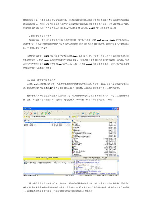
(如图1)文件下载法是最简单的不借助任何工具即可完成的网络传输速度测量方法,不过这个方法也存在着比较大的误差,我们的测量结果也会随着选择服务器的网络状况变化而改变,特别是当选择了电信服务器时下载速度将没有任何说服力。
而且服务器选择也比较麻烦,不能被限制速度也不能够被限制会话连接数。
Jperf使用方法
精心整理
2019年9月
Jperf 使用方法
Jperf 是Iperf 在windows 系统下的一种拓展软件,从原来的DOS 黑白显示增加了更加人性化的UI 界面,下面对Jperf 的使用方法做简单介绍。
一、 软件安装
否二、 图IP IP 地址,Parallel Streams 为并发数,可以根据测试情况任意填写。
需要开始测试时点击开始按钮。
图4 客户端设置
在图5显示中Transmit 设置为测试时间,Output Format 为测试结果显示格式,这里推荐使用MBits ,可以在测试结果中更加直观的显示结果。
精心整理
2019年9月
图5 时间和显示设置
三、 测试测试结果
在测试结果中,我们主要以客户端显示的结果为主要说明,这里我们将parallel Streams 设置为10,Transmit 设置为10秒,Output Format 设置为MBits 。
保持服务端处于运行状态,并点击客户端的开始按钮。
,0至10[1876] 0.0-10.0 sec 11.2 MBytes 9.37 Mbits/sec
[SUM] 0.0-10.0 sec 111 MBytes 93.2 Mbits/sec /*10秒总计传输111MBytes ,总带宽为93.2Mbps*/
图6 结果输出
.
因为两台电脑通过有线的方式进行连接,连接带宽为均为100Mbps,所以显示的结果较为接近真实带宽。
!《
.。
wifi测试测试规范
WiFi测试规范测试目的1、测试机顶盒的wifi性能是否满足需求2、对比测试机顶盒的wifi性能,判断盒子wifi性能的好坏测试环境1、无其他wifi信号干扰的测试环境注:可用手机下载wifi分析仪查看测试环境周围的wifi情况,如下图2、根据实际测试目的与要求搭建测试环境测试设备笔记本电脑、机顶盒、电视机、路由器注:1、机顶盒需要安装iperf.app软件2、JPerf2.0运行环境操作系统:Java运行环境:JREjxpiinstall.exe网络要求:Jperf可以在任何IP 网络上运行,包括本地以太网,因特网接入连接和Wi-Fi网络。
测试过程一、机顶盒可以安装.app软件,如:STB-6015C1、机顶盒当server端①、打开机顶盒并建立wifi热点;②、电脑通过无线连接机顶盒建立的热点;③、打开机顶盒iperf软件,在iperf的输入框下,输入如下命令:iperf –s –f m –i 1然后点击打开;④、运行jperf.bat 设置信息如下图;注:1、Iperf command是根据设置自动生成的,不需要手动输入。
2、server address是机顶盒的IP地址,此时可根据电脑连接的无线IP地址,写入机顶盒的IP地址。
⑥、点击右上方运行即可开始测试2、机顶盒当client端①、用路由器建立无线wifi②、电脑与机顶盒均连接此路由器的无线wifi,并记录下此时机顶盒的IP地址③、剩余测试步骤与机顶盒当服务端时的步骤一致二、机顶盒无法安装APP软件,如:STB-9832C11、机顶盒通过有线连接网络,并建立wifi热点。
2、通过串口命令,将测试软件挂在到机顶盒上将iperf放置于U盘根目录下,然后插到机顶盒上,并通过串口输入以下命令(机顶盒所用软件必须打开了串口才可以输入进去)killall -9 mickeymount -o rw,remount /root/mount /dev/sda1 /mnt/usb/cp /mnt/usb/iperf /root/synccd /root./iperf -s -f m -i 13、打开测试工具,开始测试测试步骤与上面一致测试结果附件一:网络性能测试工具iperf详细使用图文教程Iperf是一个网络性能测试工具。
JPerf2.0使用图文教程
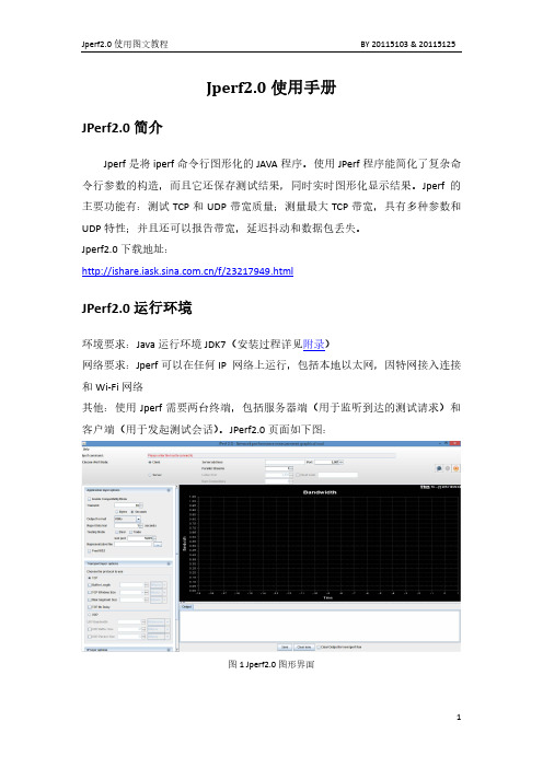
Jperf2.0使用手册JPerf2.0简介Jperf是将iperf命令行图形化的JAVA程序。
使用JPerf程序能简化了复杂命令行参数的构造,而且它还保存测试结果,同时实时图形化显示结果。
Jperf的主要功能有:测试TCP和UDP带宽质量;测量最大TCP带宽,具有多种参数和UDP特性;并且还可以报告带宽,延迟抖动和数据包丢失。
Jperf2.0下载地址:/f/23217949.htmlJPerf2.0运行环境环境要求:Java运行环境JDK7(安装过程详见附录)网络要求:Jperf可以在任何IP 网络上运行,包括本地以太网,因特网接入连接和Wi-Fi网络其他:使用Jperf需要两台终端,包括服务器端(用于监听到达的测试请求)和客户端(用于发起测试会话)。
JPerf2.0页面如下图:图1 Jperf2.0图形界面Jperf2.0功能介绍将下载好的jperf-2.0.0压缩包进行解压,双击jperf.bat打开图形界面。
图2 jperf2.0.0文件夹1、Iperf命令行(无法直接输入)2、服务器端设置3、客户端设置4、应用层设置兼容旧版本(当server端和client端版本不一样时使用)设置测试模式:传输字节总量大小10Bytes或者按传输时间总长度10秒同时进行双向传输测试单独进行双向传输测试,先测客户端到服务器的带宽指定需要传输的文件显示tcp最大mtu值5、传输层设置(1)TCP协议⏹设置缓冲区大小⏹指定TCP窗口大小⏹设定TCP数据包最大mtu值⏹设定TCP不延时(2)UDP协议⏹设置UDP最大带宽⏹设置UDP缓冲区⏹UDP包封装大小6、网络层设置⏹指定TTL值⏹服务器类型⏹绑定主机Jperf2.0测试举例1、TCP测试(1)客户端设置传输时间为10s,端口号为5001,TCP缓冲区长度为2MBytes(默认),TCP窗口大小56KBytes(默认),最大传输单元为1KBytes(默认)图3 应用层配置图4 传输层配置bin/iperf.exe -c 192.168.250.104 -P 1 -i 1 -p 5001 -w 56K -M 1K -l 2M -f M -t 10------------------------------------------------------------Client connecting to 192.168.250.104, TCP port 5001TCP window size: 0.05 MByte------------------------------------------------------------[376] local 192.168.250.103 port 48771 connected with 192.168.250.104 port 5001[ ID] Interval Transfer Bandwidth[376] 0.0- 1.0 sec 2.00 MBytes 2.00 MBytes/sec[376] 1.0- 2.0 sec 0.00 MBytes 0.00 MBytes/sec[376] 2.0- 3.0 sec 0.00 MBytes 0.00 MBytes/sec[376] 3.0- 4.0 sec 2.00 MBytes 2.00 MBytes/sec[376] 4.0- 5.0 sec 0.00 MBytes 0.00 MBytes/sec[376] 5.0- 6.0 sec 2.00 MBytes 2.00 MBytes/sec[376] 6.0- 7.0 sec 0.00 MBytes 0.00 MBytes/sec[376] 7.0- 8.0 sec 2.00 MBytes 2.00 MBytes/sec[376] 8.0- 9.0 sec 0.00 MBytes 0.00 MBytes/sec[376] 9.0-10.0 sec 2.00 MBytes 2.00 MBytes/sec[376] 0.0-11.0 sec 12.0 MBytes 1.09 MBytes/secDone.传输结果如下图所示:(2)服务器端bin/iperf.exe -s -P 0 -i 1 -p 5001 -w 56K -M 1K -l 2M -f M------------------------------------------------------------Server listening on TCP port 5001TCP window size: 0.05 MByte------------------------------------------------------------[328] local 192.168.250.104 port 5001 connected with 192.168.250.103 port 48771 [ ID] Interval Transfer Bandwidth[328] 0.0- 1.0 sec 1.07 MBytes 1.07 MBytes/sec[328] 1.0- 2.0 sec 0.93 MBytes 0.93 MBytes/sec[328] 2.0- 3.0 sec 0.00 MBytes 0.00 MBytes/sec[328] 3.0- 4.0 sec 2.00 MBytes 2.00 MBytes/sec[328] 4.0- 5.0 sec 0.00 MBytes 0.00 MBytes/sec[328] 5.0- 6.0 sec 2.00 MBytes 2.00 MBytes/sec[328] 6.0- 7.0 sec 0.00 MBytes 0.00 MBytes/sec[328] 7.0- 8.0 sec 2.00 MBytes 2.00 MBytes/sec[328] 8.0- 9.0 sec 0.00 MBytes 0.00 MBytes/sec[328] 9.0-10.0 sec 2.00 MBytes 2.00 MBytes/sec[328] 0.0-11.0 sec 12.0 MBytes 1.10 MBytes/secDone.传输结果如下图所示:2、UDP测试(1)客户端设置传输时间为10s,带宽为1Mbytes,UDP缓冲区1MBytes(默认),数据包大小为32KBytes(默认)bin/iperf.exe -c 192.168.250.104 -u -P 1 -i 1 -p 5001 -w 41K -f M -b 1M -t 10 -T 1------------------------------------------------------------Client connecting to 192.168.250.104, UDP port 5001Sending 1470 byte datagramsUDP buffer size: 0.04 MByte------------------------------------------------------------[360] local 192.168.250.103 port 63212 connected with 192.168.250.104 port 5001 [ ID] Interval Transfer Bandwidth[360] 0.0- 1.0 sec 0.12 MBytes 0.12 MBytes/sec[360] 1.0- 2.0 sec 0.12 MBytes 0.12 MBytes/sec[360] 2.0- 3.0 sec 0.12 MBytes 0.12 MBytes/sec[360] 3.0- 4.0 sec 0.12 MBytes 0.12 MBytes/sec[360] 4.0- 5.0 sec 0.12 MBytes 0.12 MBytes/sec[360] 5.0- 6.0 sec 0.12 MBytes 0.12 MBytes/sec[360] 6.0- 7.0 sec 0.12 MBytes 0.12 MBytes/sec[360] 7.0- 8.0 sec 0.12 MBytes 0.12 MBytes/sec[360] 8.0- 9.0 sec 0.12 MBytes 0.12 MBytes/sec[360] 9.0-10.0 sec 0.12 MBytes 0.12 MBytes/sec[360] 0.0-10.0 sec 1.19 MBytes 0.12 MBytes/sec[360] Server Report:[360] 0.0-10.0 sec 1.19 MBytes 0.12 MBytes/sec 3.107 ms 0/ 852 (0%) [360] Sent 852 datagramsDone.传输结果如下图所示:(2)服务器端bin/iperf.exe -s -u -P 0 -i 1 -p 5001 -f M------------------------------------------------------------Server listening on UDP port 5001Receiving 1470 byte datagramsUDP buffer size: 0.01 MByte (default)------------------------------------------------------------[212] local 192.168.250.104 port 5001 connected with 192.168.250.103 port 63212[ ID] Interval Transfer Bandwidth Jitter Lost/Total Datagrams [212] 0.0- 1.0 sec 0.12 MBytes 0.12 MBytes/sec 2.688 ms 1380930387/ 85 (1.6e+009%)[212] 1.0- 2.0 sec 0.12 MBytes 0.12 MBytes/sec 4.568 ms 0/ 84 (0%)[212] 2.0- 3.0 sec 0.12 MBytes 0.12 MBytes/sec 2.953 ms 0/ 86 (0%)[212] 3.0- 4.0 sec 0.12 MBytes 0.12 MBytes/sec 2.030 ms 0/ 85 (0%)[212] 4.0- 5.0 sec 0.12 MBytes 0.12 MBytes/sec 2.919 ms 0/ 85 (0%)[212] 5.0- 6.0 sec 0.12 MBytes 0.12 MBytes/sec 1.755 ms 0/ 85 (0%)[212] 6.0- 7.0 sec 0.12 MBytes 0.12 MBytes/sec 3.777 ms 0/ 85 (0%)[212] 7.0- 8.0 sec 0.12 MBytes 0.12 MBytes/sec 2.764 ms 0/ 85 (0%)[212] 8.0- 9.0 sec 0.12 MBytes 0.12 MBytes/sec 3.590 ms 0/ 85 (0%)[212] 9.0-10.0 sec 0.12 MBytes 0.12 MBytes/sec 2.851 ms 0/ 85 (0%)[212] 0.0-10.0 sec 1.19 MBytes 0.12 MBytes/sec 3.107 ms 0/ 852 (0%)传输结果如下图所示:由上述结果可以看出,UDP传输速度为0.12MBytes/s,总时延为3.107ms,无丢失数据包(0/852),总传输为1.19MBytes。
频谱分析仪使用方法_百度文库.

目录频谱分析仪操作指南 ................................................................................................... 1第一节仪表板描述 .. (1)一、前面板 (1)二、后面板 (略 . (6)第二节基本操作 (6)一、菜单操作和数据输入 (6)二、显示频谱和操作标记 (8)三、测试窗口和显示线 (12)四、利用横轴测试频率 (16)五、自动调整 (19)七、 UNCAL 信息 ............................................................................................. 22 第三节菜单功能描述 (24)频谱分析仪操作指南 JV 手机维修处频谱分析仪操作指南第一节仪表板描述一、前面板这部分包括前面控制板详细的视图、按键解释和显示在那些图片上的连接器, 这可从频谱仪的前部面板看到,共分为九个部分,如下所述:1、显示部分21 23、软盘驱动部分4、 MEASUREMENT 部分1 24 □5STOP635、 DATA 部分6、 MARKER 部分447、 CONTROL 部分1 68、 SYSTEM 部分□ REMOTE1 PRESET3 49、混杂的部分10、屏幕注释312图 1屏幕注释二、后面板 (略第二节基本操作一、菜单操作和数据输入用面板按键和选项去操作频谱分析仪。
使用面板键时, 一个常见的菜单会显示在屏幕的右边。
但是,有一些键没有相关的软菜单,如 AUTO TUNE和 COPY 键。
每菜单选项与功能键一一对应。
选择一个菜单,需要按相应的功能键。
在一些情形中, 按功能键显示附加选项。
下面的例子指出了仪表板和软按键功能的多少。
1、选择菜单按 LEVEL 键显示用于安装测试的菜单。
参考线值显示在活动区域中,电平菜单显示在屏幕的右边,显示如下Ref LevelATT AUTO/MNLdB/divLinearUnitsRef Offset ON/OFF2、输入数据当一个值显示在激活区时,你可利用数字键、步进键或数据旋钮改变它。
wifi测试测试规范
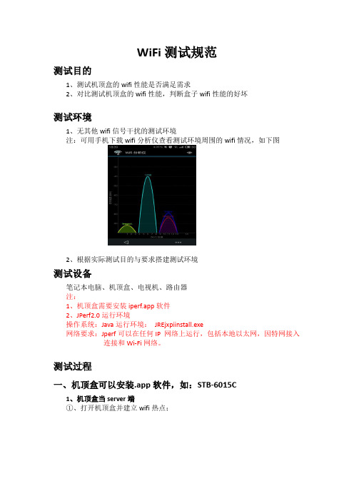
WiFi测试规范测试目的1、测试机顶盒的wifi性能是否满足需求2、对比测试机顶盒的wifi性能,判断盒子wifi性能的好坏测试环境1、无其他wifi信号干扰的测试环境注:可用手机下载wifi分析仪查看测试环境周围的wifi情况,如下图2、根据实际测试目的与要求搭建测试环境测试设备笔记本电脑、机顶盒、电视机、路由器注:1、机顶盒需要安装iperf.app软件2、JPerf2.0运行环境操作系统:Java运行环境:JREjxpiinstall.exe网络要求:Jperf可以在任何IP 网络上运行,包括本地以太网,因特网接入连接和Wi-Fi网络。
测试过程一、机顶盒可以安装.app软件,如:STB-6015C1、机顶盒当server端①、打开机顶盒并建立wifi热点;②、电脑通过无线连接机顶盒建立的热点;③、打开机顶盒iperf软件,在iperf的输入框下,输入如下命令:iperf –s –f m –i 1然后点击打开;④、运行jperf.bat 设置信息如下图;注:1、Iperf command是根据设置自动生成的,不需要手动输入。
2、server address是机顶盒的IP地址,此时可根据电脑连接的无线IP地址,写入机顶盒的IP地址。
⑥、点击右上方运行即可开始测试2、机顶盒当client端①、用路由器建立无线wifi②、电脑与机顶盒均连接此路由器的无线wifi,并记录下此时机顶盒的IP地址③、剩余测试步骤与机顶盒当服务端时的步骤一致二、机顶盒无法安装APP软件,如:STB-9832C11、机顶盒通过有线连接网络,并建立wifi热点。
2、通过串口命令,将测试软件挂在到机顶盒上将iperf放置于U盘根目录下,然后插到机顶盒上,并通过串口输入以下命令(机顶盒所用软件必须打开了串口才可以输入进去)killall -9 mickeymount -o rw,remount /root/mount /dev/sda1 /mnt/usb/cp /mnt/usb/iperf /root/synccd /root./iperf -s -f m -i 13、打开测试工具,开始测试测试步骤与上面一致测试结果附件一:网络性能测试工具iperf详细使用图文教程Iperf是一个网络性能测试工具。
jperf使用方法 -回复
jperf使用方法-回复jperf是一种性能测试工具,它由Java语言编写而成,主要用于测试网络带宽、延迟、丢包率等网络性能指标。
它可以模拟各种TCP/IP网络环境,并提供全面的统计数据,以帮助用户分析网络性能问题。
本文将详细介绍jperf的使用方法,帮助读者快速了解和开始使用这个强大的工具。
第一步:下载和安装jperf要使用jperf,首先需要从官方网站或其他可信的下载源下载安装程序。
jperf是跨平台的,适用于Windows、Linux和Mac操作系统。
下载完成后,双击安装程序并按照提示完成安装。
安装过程通常很简单,只需选择目标文件夹和一些其他选项,就可以开始使用jperf了。
第二步:启动jperf安装完成后,在桌面或启动菜单中找到jperf的图标,并双击打开它。
jperf 将弹出一个图形界面,供用户进行各种性能测试设置。
第三步:设置服务器和客户端jperf可以同时作为服务器端和客户端来运行,以便在两个主机之间进行性能测试。
首先需要选择一个主机作为服务器,然后在另一个主机上作为客户端。
通常,服务器主机应该具有更强的硬件配置和更可靠的网络连接,以确保测试结果的准确性。
在jperf主界面的上方,有一个“Server”选项卡和一个“Client”选项卡。
首先,单击“Server”选项卡,在弹出的界面中填写服务器主机的相关信息,如IP地址和端口号。
然后,单击“Start”按钮启动服务器。
接下来,切换到“Client”选项卡,在相应的界面中填写客户端主机的信息,包括服务器的IP地址和端口号。
还可以选择一些测试参数,如测试时间、传输协议等。
最后,点击“Start”按钮启动客户端。
第四步:执行性能测试一旦服务器和客户端都启动成功,jperf将开始执行性能测试。
它将模拟一系列的数据包传输,以评估网络的带宽、延迟和丢包率等指标。
在测试过程中,jperf会实时显示统计数据,以帮助用户了解性能表现。
用户可以查看传输速率、延迟、丢包和其他指标,以评估网络的健康状况。
jperf使用方法 -回复
jperf使用方法-回复jperf是一款用于测试网络性能的工具,它基于Java编写,可以通过TCP/IP 进行网络性能测试。
本文将介绍jperf的使用方法,并给出详细步骤和操作示例,以帮助用户更好地运用这个工具。
首先,我们需要下载和安装jperf。
可以在官方网站(安装完成后,我们就可以开始使用jperf进行网络性能测试了。
下面是一步一步的操作指南:步骤一:启动jperf双击jperf的可执行文件,或者通过命令行进入jperf所在的目录,运行以下命令:java -jar jperf.jar在Windows系统中,也可以通过双击“jperf.jar”文件来启动jperf。
步骤二:设置服务器端点击jperf界面上的“Server”按钮,进入服务器端设置界面。
在这里,我们需要设置服务器的IP地址和监听端口号。
默认情况下,jperf使用5001作为监听端口号。
我们可以根据需要修改这个端口号。
步骤三:设置客户端点击jperf界面上的“Client”按钮,进入客户端设置界面。
在这里,我们需要设置客户端的IP地址和服务器的IP地址以及端口号。
这里建议将服务器IP地址设置为真实网络环境中的IP地址,以便更真实地模拟网络性能。
步骤四:选择测试参数在客户端设置界面的下方,我们可以看到一些测试参数,包括测试时间、并发连接数、传输带宽等。
可以根据实际需求进行调整,以便更好地模拟网络环境。
步骤五:启动测试点击jperf界面上的“Run Iperf”按钮,即可启动网络性能测试。
jperf 将自动在服务器端和客户端之间建立连接,并进行数据传输。
在测试过程中,我们可以实时监控网络性能,并查看性能统计信息。
步骤六:查看测试结果测试完成后,jperf会自动生成测试结果报告。
我们可以在jperf界面上查看报告,并分析网络性能数据,以便评估网络的稳定性和带宽利用率。
除了以上的基本操作,jperf还提供了一些高级功能,如多线程测试、TCP窗口大小调整等。
RIdeogram 0.2.2 用户指南说明书

Package‘RIdeogram’October12,2022Type PackageTitle Drawing SVG Graphics to Visualize and Map Genome-Wide Data onIdiogramsVersion0.2.2Maintainer Zhaodong Hao<*****************>Description For whole-genome analysis,idiograms are virtually the most intuitive and effec-tive way to map and visualize the genome-wide information.RIdeogram was developed to visu-alize and map whole-genome data on idiograms with no restriction of species.License Artistic-2.0Encoding UTF-8LazyData trueDepends R(>=3.5.0)Imports ggplot2,grDevices,grImport2,rsvg,scales,tools,tidyr,utilsRoxygenNote6.1.1Suggests knitr,rmarkdownVignetteBuilder knitrNeedsCompilation noAuthor Zhaodong Hao[aut,cre],Dekang Lv[aut],Ying Ge[aut],Jisen Shi[aut],Weijers Dolf[aut],Guangchuang Yu[aut],Jinhui Chen[aut]Repository CRANDate/Publication2020-01-2011:20:02UTC12convertSVG R topics documented:convertSVG (2)Fst_between_CE_and_CW (3)gene_density (4)GFFex (4)human_karyotype (5)ideogram (5)karyotype_dual_comparison (6)karyotype_ternary_comparison (7)liriodendron_karyotype (7)LTR_density (8)Pi_for_CE (8)Pi_for_CE_and_CW (9)Random_RNAs_500 (9)synteny_dual_comparison (10)synteny_ternary_comparison (10)synteny_ternary_comparison_graident (11)Index12 convertSVG convertSVGDescriptionconvert svg to png or other formatUsageconvertSVG(svg,file="chromosome",device=NULL,width=8.2677,height=11.6929,dpi=300)svg2pdf(svg,file="chromosome",width=8.2677,height=11.6929,dpi=300)svg2png(svg,file="chromosome",width=8.2677,height=11.6929,dpi=300)svg2tiff(svg,file="chromosome",width=8.2677,height=11.6929,dpi=300)svg2jpg(svg,file="chromosome",width=8.2677,height=11.6929,dpi=300)Fst_between_CE_and_CW3 Argumentssvg svgfilefile outputfile namedevice target formatwidth output widthheight output heightdpi output dpiValueinvisible grob objectAuthor(s)Zhaodong Hao,Dekang Lv,Ying Ge,Jisen Shi,Dolf Weijers,Guangchuang Yu,Jinhui Chen Fst_between_CE_and_CW Fst between two Liriodendron groupsDescriptionFst values between China east and west groups of Liriodendron chinense and being calculated in a 2-Mb sliding window with a1-Mb stepUsagedata(Fst_between_CE_and_CW)Formatdata frameSourceNature Plants,doi:10.1038/s41477-018-0323-64GFFex gene_density Gene distribution across the human genomeDescriptionGene numbers was counted with a window of1MbUsagedata(gene_density)Formatdata frameSourceGencode(https:///)GFFex GFFexDescriptionextract some specific feature information from a gfffileUsageGFFex(input,karyotype,feature="gene",window=1e+06)Argumentsinput gfffilekaryotype karyotypefilefeature feature namewindow window sizeValuedataframeAuthor(s)Zhaodong Hao,Dekang Lv,Ying Ge,Jisen Shi,Dolf Weijers,Guangchuang Yu,Jinhui Chenhuman_karyotype5 human_karyotype Karyotype information of the human genomeDescriptionThe version of this geome is gencode.v29.Usagedata(human_karyotype)Formatdata frameSourceGencode(https:///)ideogram ideogramDescriptionideogram with overlaid heatmap annotation and optional track labelUsageideogram(karyotype,overlaid=NULL,label=NULL,label_type=NULL,synteny=NULL,colorset1=c("#4575b4","#ffffbf","#d73027"),colorset2=c("#b35806","#f7f7f7","#542788"),width=170,Lx=160,Ly=35,output="chromosome.svg")Argumentskaryotype karyotype dataoverlaid overlaid datalabel track label datalabel_type track label type,only support four types:marker,heatmap,line and polygon synteny synteny datacolorset1overlaid heatmap colorcolorset2label heatmap colorwidth width of plot regionLx position of legend(x)Ly position of legend(y)output outputfile,only svg is supported6karyotype_dual_comparisonValueoutputfileAuthor(s)Zhaodong Hao,Dekang Lv,Ying Ge,Jisen Shi,Dolf Weijers,Guangchuang Yu,Jinhui Chen Examples#Loading the packagerequire(RIdeogram)#Loading the testing datadata(human_karyotype,package="RIdeogram")data(gene_density,package="RIdeogram")data(Random_RNAs_500,package="RIdeogram")#Checking the data formathead(human_karyotype)head(gene_density)head(Random_RNAs_500)#Running the function(Remove"#"before you run the following codes)#ideogram(karyotype=human_karyotype)#convertSVG("chromosome.svg",device="png")#Then,you will find a SVG file and a PNG file in your Working Directory.karyotype_dual_comparisonKaryotype for two genome comparisonDescriptionGrape and Populus genomesUsagedata(karyotype_dual_comparison)Formatdata frameSourceMCscankaryotype_ternary_comparison7karyotype_ternary_comparisonKaryotype for three genome comparisonDescriptionAmborella,Grape and Liriodendron genomesUsagedata(karyotype_ternary_comparison)Formatdata frameSourceMCscanliriodendron_karyotypeKaryotype information of the Liriodendron genomeDescriptionLiriodendron chinense genomeUsagedata(liriodendron_karyotype)Formatdata frameSourceNature Plants,doi:10.1038/s41477-018-0323-68Pi_for_CE LTR_density LTR distribution across the human genomeDescriptionLTR numbers was counted with a window of1MbUsagedata(LTR_density)Formatdata frameSourceUCSC(/index.html)Pi_for_CE Pi of one Liriodendron groupDescriptionPi values of the China east group of Liriodendron chinense and being calculated in a2-Mb sliding window with a1-Mb stepUsagedata(Pi_for_CE)Formatdata frameSourceNature Plants,doi:10.1038/s41477-018-0323-6Pi_for_CE_and_CW9 Pi_for_CE_and_CW Pi of two Liriodendron groupsDescriptionPi values of the China east and west groups of Liriodendron chinense and being calculated in a 2-Mb sliding window with a1-Mb stepUsagedata(Pi_for_CE_and_CW)Formatdata frameSourceNature Plants,doi:10.1038/s41477-018-0323-6Random_RNAs_500500RNAs’positionDescription500RNAs randomly selected from all tRNAs,rRNAs and miRNA in the human genome.Usagedata(Random_RNAs_500)Formatdata frameSourceGencode(https:///)10synteny_ternary_comparisonsynteny_dual_comparisonSynteny for two genome comparisonDescriptionGenome Synteny between Grape and PopulusUsagedata(synteny_dual_comparison)Formatdata frameSourceMCscansynteny_ternary_comparisonSynteny for three genome comparisonDescriptionGenome Synteny among Amborella,Grape and LiriodendronUsagedata(synteny_ternary_comparison)Formatdata frameSourceMCscansynteny_ternary_comparison_graident11synteny_ternary_comparison_graidentSynteny for three genome comparison with gradientfillDescriptionGenome Synteny among Amborella,Grape and Liriodendron with gradientfillUsagedata(synteny_ternary_comparison_graident)Formatdata frameSourceMCscanIndex∗datasetsFst_between_CE_and_CW,3gene_density,4human_karyotype,5karyotype_dual_comparison,6karyotype_ternary_comparison,7liriodendron_karyotype,7LTR_density,8Pi_for_CE,8Pi_for_CE_and_CW,9Random_RNAs_500,9synteny_dual_comparison,10synteny_ternary_comparison,10synteny_ternary_comparison_graident, 11convertSVG,2Fst_between_CE_and_CW,3gene_density,4GFFex,4human_karyotype,5ideogram,5karyotype_dual_comparison,6karyotype_ternary_comparison,7 liriodendron_karyotype,7LTR_density,8Pi_for_CE,8Pi_for_CE_and_CW,9Random_RNAs_500,9svg2jpg(convertSVG),2svg2pdf(convertSVG),2svg2png(convertSVG),2svg2tiff(convertSVG),2synteny_dual_comparison,10synteny_ternary_comparison,10synteny_ternary_comparison_graident,1112。
jperf测试方法

1、搭建测试网络环境,如图:
2、客户端和服务器均安装JDK开发环境,配置相应环境变量
3、配置服务器参数。
服务器运行jperf.bat文件,进入程序界面
(1)choose iPerf Mode处选择server,其他默认。
如图:
(2)Output Format(输出结果显示单位),根据需要选择,默认即可(3)transport选择UDP,如图:
(4)运行程序。
点击右上角运行按钮。
如图:
4、客户端配置。
打开CMD命令行,进入iperf-2.0.0\bin目录,如图:
5、输入客户端控制发送包命令:如图:
命令解释:
-l 470B:数据包大小,可以控制帧长,数据包加上42等于帧长(根据具体网卡进行换算,实际帧长以wireshark中Frame大小为准)
-b 27837K:带宽大小,可以控制发送速率。
带宽与速率的换算为:带宽/8=速率
-F D:\Windows.2003 发送的文件名称(可自行修改,200M左右就可以)
-t 10 发送时间为10秒
注意:命令中的单位:B为Byte,b为bit,带宽单位为bit/s,速率单位为byte/s
6、运行上述命令后可得出丢包率、延时、背靠背数值。
客户端结果:
服务器结果:
服务器最后一条结果为测试结果
从上述结果可以看出,0-10秒内,传输数据总工大小为33341KB,平均速率27355Kbits/sec,延时为0.000ms,丢包个数为744,传输总包数为73384。
JPerf2.0测试方法
JPerf2.0测试方法JPerf2.0简介Jperf是将iperf命令行图形化的JAVA程序;使用JPerf程序能简化了复杂命令行参数的构造,而且它还保存测试结果,同时实时图形化显示结果。
JPerf可以测试TCP和UDP带宽质量。
JPerf可以测量最大TCP带宽,具有多种参数和UDP特性。
JPerf可以报告带宽,延迟抖动和数据包丢失。
JPerf2.0运行环境操作系统:Java运行环境:JREjxpiinstall.exe网络要求:Jperf可以在任何IP 网络上运行,包括本地以太网,因特网接入连接和Wi-Fi 网络。
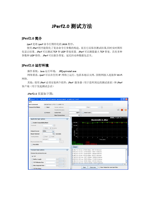
其他:使用JPerf必须安装两个组件:JPerf 服务器(用于监听到达的测试请求)和JPerf 客户端(用于发起测试会话)JPerf2.0页面如下图:JPerf2.0具体介绍一、Iperf命令行(无法直接输入)二、服务端设置监听端口:5001三、客户端设置服务器地址:10.0.115.82 ,端口:5001 ,并发流:1个四、应用层设置1、兼容旧版本(当server端和client端版本不一样时使用)2、设置测试模式:传输字节总量大小15Bytes或者按传输时间总长度15秒3、同时进行双向传输测试4、单独进行双向传输测试,先测c到s的带宽5、指定需要传输的文件6、显示tcp最大mtu值五、传输层设置1、TCP协议设置缓冲区大小指定TCP窗口大小设定TCP数据包的最大mtu值设定TCP不延时2、UDP协议设置UDP最大带宽设置UDP缓冲区UDP包封装大小:默认1470 byte六、IP层设置1、指定ttl值2、服务类型(Type of Service,ToS),大小范围从0x10 (最小延迟) 到0x2 (最少费用)在使用802.11e来控制服务质量的WLAN中,ToS是映射在Wi-Fi多媒体(WMM)存取范畴的。
JPerf2.0测试举例:一、测试内容(UDP):UDP buffer size:默认,0.01MUDP packet size:默认,1470 byte端口:5001TTL:1测试网卡带宽:1000M测试总时间:10 s时间间隔:1 s显示单位:M测试流:1个二、客户端:bin/iperf.exe -c 10.0.115.82 -u -P 1 -i 1 -p 5001 -f M -b 1000M -t 10 -T 1 -FC:\Documents and Settings\Administrator\桌面\Clip2_CCTV5_NBA_3.75M_V3.3M_A160k.tsUnable to open the file streamWill use the default data stream------------------------------------------------------------Client connecting to 10.0.115.82, UDP port 5001Sending 1470 byte datagramsUDP buffer size: 0.01 MByte (default)------------------------------------------------------------[1832] local 10.0.115.54 port 3297 connected with 10.0.115.82 port 5001[ ID] Interval Transfer Bandwidth[1832] 0.0- 1.0 sec 3.46 MBytes 3.46 MBytes/sec[1832] 1.0- 2.0 sec 3.32 MBytes 3.32 MBytes/sec[1832] 2.0- 3.0 sec 3.43 MBytes 3.43 MBytes/sec[1832] 3.0- 4.0 sec 3.42 MBytes 3.42 MBytes/sec[1832] 4.0- 5.0 sec 3.43 MBytes 3.43 MBytes/sec[1832] 5.0- 6.0 sec 3.39 MBytes 3.39 MBytes/sec[1832] 6.0- 7.0 sec 3.43 MBytes 3.43 MBytes/sec[1832] 7.0- 8.0 sec 3.40 MBytes 3.40 MBytes/sec[1832] 8.0- 9.0 sec 3.43 MBytes 3.43 MBytes/sec[1832] 9.0-10.0 sec 3.47 MBytes 3.47 MBytes/sec[1832] 0.0-10.0 sec 34.2 MBytes 3.41 MBytes/sec[1832] Server Report:[1832] 0.0-10.0 sec 34.2 MBytes 3.41 MBytes/sec 1.953 ms 13/24378 (0.053%) [1832] Sent 24378 datagramsbin\iperf.exe: ignoring extra argument -- andbin\iperf.exe: ignoring extra argument -- Settings\Administrator\桌面\Clip2_CCTV5_NBA_3.75M_V3.3M_A160k.tsDone.三、服务端:bin/iperf.exe -s -u -P 0 -i 1 -p 5001 -f M------------------------------------------------------------Server listening on UDP port 5001Receiving 1470 byte datagramsUDP buffer size: 0.01 MByte (default)------------------------------------------------------------[1928] local 10.0.115.82 port 5001 connected with 10.0.115.54 port 3297[ ID] Interval Transfer Bandwidth Jitter Lost/Total Datagrams[1928] 0.0- 1.0 sec 3.45 MBytes 3.45 MBytes/sec 0.281 ms 1649892402/ 2462 (6.7e+007%) [1928] 1.0- 2.0 sec 3.31 MBytes 3.31 MBytes/sec 0.264 ms 0/ 2358 (0%)[1928] 2.0- 3.0 sec 3.43 MBytes 3.43 MBytes/sec 0.288 ms 6/ 2450 (0.24%)[1928] 3.0- 4.0 sec 3.42 MBytes 3.42 MBytes/sec 0.271 ms 4/ 2445 (0.16%)[1928] 4.0- 5.0 sec 3.43 MBytes 3.43 MBytes/sec 0.269 ms 0/ 2446 (0%)[1928] 5.0- 6.0 sec 3.39 MBytes 3.39 MBytes/sec 0.662 ms 0/ 2417 (0%)[1928] 6.0- 7.0 sec 3.43 MBytes 3.43 MBytes/sec 0.252 ms 0/ 2446 (0%)[1928] 7.0- 8.0 sec 3.40 MBytes 3.40 MBytes/sec 0.232 ms 3/ 2429 (0.12%)[1928] 8.0- 9.0 sec 3.43 MBytes 3.43 MBytes/sec 0.083 ms 0/ 2448 (0%)[1928] 9.0-10.0 sec 3.47 MBytes 3.47 MBytes/sec 0.218 ms 0/ 2474 (0%)[1928] 0.0-10.0 sec 34.2 MBytes 3.41 MBytes/sec 1.953 ms 13/24378 (0.053%)四、测试结果[1832] 0.0-10.0 sec 34.2 MBytes 3.41 MBytes/sec 1.953 ms 13/24378(0.053%)[1832] Sent 24378 datagrams链路传输UDP速度:3.42MBytes/sec总延时:1.953ms丢包:13个占0.053%总传输:34.2MB。
jperf使用方法
jperf使用方法
JPerf是一个将iPerf命令行界面图形化的JAVA程序,可以测试TCP和UDP带宽质量,测量最大TCP带宽,具有多种参数和UDP特性,并可以
报告带宽、延迟抖动和数据包丢失。
关于如何使用JPerf,有以下两种方式:
1. 使用JPerf的图形化界面,该界面能够简化复杂命令行参数的构造,并且能保存测试结果,同时实时图形化显示结果。
2. 使用命令行进行操作,JPerf在命令行中的使用方式和iPerf类似。
例如:`java -jar -server [服务器地址]`。
此外,JPerf可以在任何IP网络上运行,包括本地以太网、因特网接入连接和Wi-Fi网络。
以上信息仅供参考,具体使用方法可以查阅相关教程或咨询专业人士。
GxEScanR 2.0.2 用户指南说明书
Package‘GxEScanR’October12,2022Type PackageTitle Run GWAS/GWEIS Scans Using Binary Dosage FilesVersion2.0.2Date2020-10-02Description Tools to run genome-wide association study(GW AS)andgenome-wide by environment interaction study(GWEIS)scans using the geneticdata stored in a binary dosagefile.The user provides a data frame withthe subject's covariate data and the information about the binary dosagefile returned by the BinaryDosage::getbdinfo()routine.License GPL-3Encoding UTF-8Language en-USImports Rcpp(>=1.0.4),prodlimLinkingTo Rcpp,RcppArmadilloRoxygenNote7.1.1Suggests BinaryDosage,testthat(>=2.1.0),covr,knitr,rmarkdownVignetteBuilder knitrNeedsCompilation yesAuthor John Morrison[aut,cre],NCI[fnd](CA196559),NCI[fnd](CA201407),NIEHS[fnd](ES007048),NHLBI[fnd](HL115606)Maintainer John Morrison<*************>Repository CRANDate/Publication2020-10-0221:52:09UTCR topics documented:gwas (2)gweis (3)12gwas Index4 gwas gwasDescriptionRun a gwas using genetic data from a binary dosagefileUsagegwas(data,bdinfo,snps,outfile,skipfile,minmaf,blksize,binary)Argumentsdata Data frame containing the subject ID,phenotype and covariatesbdinfo Information about the binary dosagefile returned from the BinaryDosage::getbdinfo routinesnps The SNPs to be used in the scan.This may be an integer vector indicate whichSNPs to use in the binary dosagefile or a character vector of the SNP IDs touse.The value may also be"all",indicating to use all SNPs.The default valueis"all".outfile Thefile name for the results Can be blank.If the value is"",the results arereturned as a data frame.Default value is""skipfile The name of thefile to write the SNPs that were not used and the reason theyweren’t used.If the value is blank,there is no output of the unused SNPs.Default value is"".minmaf Minimum minor allele frequency of SNPs to include in analysis.SNPS that haveless than20minor alleles observed will be excluded from the analysis regardlessof the value of minmaf.A value of0indicates to use all the SNPs that have20minor alleles observed.Default value is0.blksize Size of blocks of SNPs to read in at one rger blocks can improve overallspeed but require larger amounts of computer memory.A value of0indicates touse the recommended block size.Default value is0.binary Logical value indicating if the phenotype is a binary value.Default value isfalse.ValueExamplesbdinfo<-readRDS(system.file("extdata/pdata_4_1.bdinfo",package="GxEScanR"))covdata<-readRDS(system.file("extdata/covdata.rds",package="GxEScanR"))results<-gwas(data=covdata,bdinfo=bdinfo,binary=FALSE)gweis3 gweis gweisDescriptionRun a gweis using genetic data from a binary dosagefileUsagegweis(data,bdinfo,snps,outfile,skipfile,minmaf,blksize,binary)Argumentsdata Data frame containing the subject ID,phenotype and covariatesbdinfo Information about the binary dosagefile returned from the BinaryDosage::getbdinfo routinesnps The SNPs to be used in the scan.This may be an integer vector indicate whichSNPs to use in the binary dosagefile or a character vector of the SNP IDs touse.The value may also be"all",indicating to use all SNPs.The default valueis"all".outfile Thefile name for the results Can be blank.If the value is"",the results arereturned as a data frame.Default value is""skipfile The name of thefile to write the SNPs that were not used and the reason theyweren’t used.If the value is blank,there is no output of the unused SNPs.Default value is"".minmaf Minimum minor allele frequency of SNPs to include in analysis.SNPS that haveless than20minor alleles observed will be excluded from the analysis regardlessof the value of minmaf.A value of0indicates to use all the SNPs that have20minor alleles observed.Default value is0.blksize Size of blocks of SNPs to read in at one rger blocks can improve overallspeed but require larger amounts of computer memory.A value of0indicates touse the recommended block size.Default value is0.binary Logical value indicating if the phenotype is a binary value.Default value isfalse.ValueExamplesbdinfo<-readRDS(system.file("extdata/pdata_4_1.bdinfo",package="GxEScanR"))covdata<-readRDS(system.file("extdata/covdata.rds",package="GxEScanR"))results<-gweis(data=covdata,bdinfo=bdinfo)Indexgwas,2gweis,34。
Jperf使用手册-

Jperf使用手册1引言 (3)1.1JPerf2.0简介 (3)1.2JPerf2.0运行环境 (3)1.3JPerf2.0具体介绍 (3)1.3.1界面参数说明: (4)2Jperf操作步骤 (7)2.1服务端操作步骤 (7)2.1.1服务端安装配置JRE环境 (7)2.1.2服务端运行jperf: (7)2.2客户端操作步骤: (9)2.2.1客服端安装配置JRE环境 (9)2.2.2客户端运行jperf软件 (9)2.3测试结果分析 (11)3注意事项 (13)3.1.1测试时启动问题 (13)3.1.2服务端启动配置问题 (13)4附录 (14)4.1Iperf参数说明 (14)1 引言1.1 JPerf2.0简介Jperf是将iperf命令行图形化的JA V A程序;使用JPerf程序能简化了复杂命令行参数的构造,而且它还保存测试结果,同时实时图形化显示结果。
JPerf可以测试TCP和UDP带宽质量。
JPerf可以测量最大TCP带宽,具有多种参数和UDP特性。
JPerf可以报告带宽,延迟抖动和数据包丢失。
1.2 JPerf2.0运行环境操作系统:Java运行环境:JREinstall.exe网络要求:Jperf可以在任何IP 网络上运行,包括本地以太网,因特网接入连接和Wi-Fi网络。
其他:使用JPerf必须安装两个组件:JPerf 服务器(用于监听到达的测试请求)和JPerf客户端(用于发起测试会话)1.3 JPerf2.0具体介绍JPerf2.0页面如下图:图1.Jperf2.0.0-Server端运行界面图2.Jperf2.0.0-Server端运行界面1.3.1 界面参数说明:图3.Jperf启动参数设置图4.传输设置图5.应用层设置图6.带宽曲线显示图图7.结果日志输出窗口2 Jperf操作步骤2.1 服务端操作步骤2.1.1 服务端安装配置JRE环境安装java运行环境,JDK或JRE;2.1.2 服务端运行jperf:1、解压jperf-2.0.0.zip压缩包,双击运行其中的jperf.bat文件,弹出如下窗口:图8.Server端iperf运行开始界面2、选中iperf运行模式为server,点击Run IPerf!按钮(默认监听端口为5001,如果该端口被占用请修改监听端口,再运行!!)图9.Server端jperf启动时输入参数界面3、出现如下图所示窗口时server端iperf运行成功!图10.Iperf server端运行后界面2.2 客户端操作步骤:2.2.1 客服端安装配置JRE环境安装java运行环境,JDK或JRE;2.2.2 客户端运行jperf软件1、解压jperf-2.0.0.zip压缩包,双击运行其中的jperf.bat文件,弹出如下窗口:图11.Jperf运行开始界面2、选中iperf运行模式为client,输入服务端ip外网地址,点击Run IPerf!按钮(其他参数默认即可)图12.启动client端时输入参数界面3、出现如下图所示窗口时client端iperf启动运行成功!启动运行后client端界面2.3 测试结果分析测试运行结果[156] 0.0- 9.9 sec 1219 KBytes 123 KBytes/sec 5.901 ms 3/ 852 (0.35%)0.0- 9.9 sec:测试总时间:10s1219 KBytes:总传输1219 KBytes123 KBytes/sec:链路传输UDP带宽123 KBytes/sec5.901 ms:总延时5.901 ms3/ 852 (0.35%):丢包3个,占总包0.35%Ping Result:数据包: 已发送= 4,已接收= 4,丢失= 0 (0% 丢失),最短= 1ms,最长= 1ms,平均= 1ms,jitter :0.0msPing结果:发送4个包,接收4个包,丢失0个,丢失百分比:0%最短延时:1ms,最长延时:1msJitter:抖动0.0ms3 注意事项3.1.1 测试时启动问题测试时,服务端和客户端启动时间间隔不要过长,否则会对测试结果有些偏差;3.1.2 服务端启动配置问题启动服务端时,最好设置客户端连接数为1,如果多个客户端连接服务端会占用一定带宽;4 附录4.1 Iperf参数说明参数说明-s 以server模式启动,eg:iperf -s-c host 以client模式启动,host是server端地址,eg:iperf -c 222.35.11.23通用参数-f [k|m|K|M] 分别表示以Kbits, Mbits, KBytes, MBytes显示报告,默认以Mbits为单位,eg:iperf -c 222.35.11.23 -f K-i sec 以秒为单位显示报告间隔,eg:iperf -c 222.35.11.23 -i 2-l 缓冲区大小,默认是8KB,eg:iperf -c 222.35.11.23 -l 16-m 显示tcp最大mtu值-o 将报告和错误信息输出到文件eg:iperf -c 222.35.11.23 -o c:\iperflog.txt-p 指定服务器端使用的端口或客户端所连接的端口eg:iperf -s -p 9999;iperf -c 222.35.11.23 -p 9999-u 使用udp协议-w 指定TCP窗口大小,默认是8KB-B 绑定一个主机地址或接口(当主机有多个地址或接口时使用该参数)-C 兼容旧版本(当server端和client端版本不一样时使用)-M 设定TCP数据包的最大mtu值-N 设定TCP不延时-V 传输ipv6数据包server专用参数-D 以服务方式运行ipserf,eg:iperf -s -D-R 停止iperf服务,针对-D,eg:iperf -s -Rclient端专用参数-d 同时进行双向传输测试-n 指定传输的字节数,eg:iperf -c 222.35.11.23 -n 100000-r 单独进行双向传输测试-t 测试时间,默认10秒,eg:iperf -c 222.35.11.23 -t 5-F 指定需要传输的文件-T 指定ttl值操作举例:1)TCP测试服务器执行:#iperf -s -i 1 -w 1M客户端执行:#iperf -c host -i 1 -w 1M其中-w表示TCP window size,host需替换成服务器地址。
- 1、下载文档前请自行甄别文档内容的完整性,平台不提供额外的编辑、内容补充、找答案等附加服务。
- 2、"仅部分预览"的文档,不可在线预览部分如存在完整性等问题,可反馈申请退款(可完整预览的文档不适用该条件!)。
- 3、如文档侵犯您的权益,请联系客服反馈,我们会尽快为您处理(人工客服工作时间:9:00-18:30)。
注意:在计算字节byte时,Kilo = 1024, Mega = 1024^2,Giga = 1024^3。通常,在网络中,Kilo = 1000, Mega = 1000^2, and Giga = 1000^3,所以,Iperf也按此来计算比特(位)。如果这些困扰了你,那么请使用-f b参数,然后亲自计算一下。
-P, --parallel # $IPERF_PARALLEL 线程数。指定客户端与服务端之间使用的线程数。默认是1线程。需要客户端与服务器端同时使用此参数。
-S, --tos # $IPERF_TOS 出栈数据包的服务类型。许多路由器忽略TOS字段。你可以指定这个值,使用以“0x”开始的16进制数,或以“0”开始的8进制数或10进制数。
-m, --print_mss $IPERF_PRINT_MSS 输出TCP MSS值(通过TCP_MAXSEG支持)。MSS值一般比MTU值小40字节。通常情况
-p, --port # $IPERF_PORT 设置端口,与服务器端的监听端口一致。默认是5001端口,与ttcp的一样。
-u, --udp $IPERF_UDP 使用UDP方式而不是TCP方式。参看-b选项。
-P, --parallel # $IPERF_PARALLEL 服务器关闭之前保持的连接数。默认是0,这意味着永远接受连接。
客户端专用选项
-b, --bandwidth #[KM] $IPERF_BANDWIDTH UDP模式使用的带宽,单位bits/sec。此选项与-u选项相关。默认值是1 Mbit/sec。
Usage: iperf [-s|-c host] [options]
iperf [-h|--help] [-v|--version]
命令行选项 环境变量选项 描述
客户端与服务器端选项
-f, --format [bkmaBKMA] $IPERF_FORMAT 格式化带宽数输出。支持的格式有:
其中-b表示使用多少带宽,1G的线路你可以使用900M进行测试。
编辑本段功能介绍
l TCP
n 测量网络带宽
n 报告MSS/MTU值的大小和观测值
n 支持TCP窗口值通过套接字缓冲
n 当P线程或Win32线程可用时,支持多线程。客户端与服务端支持同时多重连接
l UDP
iperf 分为两种版本,unix/linux版和windows版,unix/linux版更新比较快,版本最新。windows版更新慢。windows版的iperf叫jperf,或者xjperf。jperf是在iperf基础上开发了更好的UI和新的功能。
编辑本段iperf的参数
[root]# iperf -h
l 可以指定运行的总时间,甚至可以设置传输的数据总量。
l 在报告中,为数据选用最合适的单位。
l 服务器支持多重连接,而不是等待一个单线程测试。
l 在指定时间间隔重复显示网络带宽,波动和丢包情况。
l 服务器端可作为后台程序运行。
l 服务器端可作为Windows 服务运行。
-i, --interval # $IPERF_INTERVAL 设置每次报告之间的时间间隔,单位为秒。如果设置为非零值,就会按照此时间间隔输出测试报告。默认值为零。
-l, --len #[KM] $IPERF_LEN 设置读写缓冲区的长度。TCP方式默认为8KB,UDP方式默认为1470字节。
-C, --compatibility $IPERF_COMPAT 与低版本的Iperf使用时,可以使用兼容模式。不需要两端同时使用兼容模式,但是强烈推荐两端同时使用兼容模式。某些情况下,使用某些数据流可以引起1.7版本的服务器端崩溃或引起非预期的连接尝试。
-M, --mss #[KM} $IPERF_MSS 通过TCP_MAXSEG选项尝试设置TCP最大信息段的值。MSS值的大小通常是TCP/IP头减去40字节。在以太网中,MSS值 为1460字节(MTU1500字节)。许多操作系统不支持此选项。
'b' = bits/sec 'B' = Bytes/sec
'k' = Kbits/sec 'K' = KBytes/sec
'm' = Mbits/sec 'M' = MBytes/sec
'g' = Gbits/sec 'G' = GBytes/sec
'a' = adaptive bits/sec 'A' = adaptive Bytes/sec
n 客户端可以创建指定带宽的UDP流
n 测量丢包
n 测量延迟
n 支持多播
n 当P线程可用时,支持多线程。客户端与服务端支持同时多重连接(不支持Windows)
l 在适当的地方,选项中可以使用K(kilo-)和M(mega-)。例如131072字节可以用128K代替。
例如,16进制'0x10' = 8进制'020' = 十进制'16'。TOS值1349就是:
IPTOS_LOWDELAY minimize delay 0x10
IPTOS_THROUGHPUT maximize throughput 0x08
IPTOS_RELIABILITY maximize reliability 0x04
iperf
目录
概览:
iperf的参数
实例
功能介绍
编辑本段概览:
Iperf 是一个网络性能测试工具。Iperf可以测试最大TCP和UDP带宽性能。Iperf具有多种参数和UDP特性,可以根据需要调整。Iperf可以报告带宽,延迟抖动和数据包丢失。
-N, --nodelay $IPERF_NODELAY 设置TCP无延迟选项,禁用Nagle's运算法则。通常情况此选项对于交互程序,例如telnet,是禁用的。
-V (from v1.6 or higher)
绑定一个IPv6地址。
服务端:$ iperf -s –V
客户端:$ iperf -c <Server IPv6 Address> -V
IPTOS_LOWCOST minimize cost 0x02
-T, --ttl # $IPERF_TTL 出栈多播数据包的TTL值。这本质上就是数据通过路由器的跳数。默认是1,链接本地。
-F (from v1.2 or higher)
使用特定的数据流测量带宽,例如指定的文件。
$ iperf -c <server address> -F <file-name>
-c, --client host $IPERF_CLIENT 运行Iperf的客户端模式,连接到指定的Iperf服务器端。
-d, --dualtest $IPERF_DUALTEST 运行双测试模式。这将使服务器端反向连接到客户端,使用-L 参数中指定的端口(或默认使用客户端连接到服务器端的端口)。这些在操作的同时就立即完成了。如果你想要一个交互的测试,请尝试-r参数。
注意:在1.6.3或更高版本中,指定IPv6地址不需要使用-B参数绑定,在1.6之前的版本则需要。在大多数操作系统中,将响应IPv4客户端映射的IPv4地址。
服务器端专用选项
-s, --server $IPERF_SERVER Iperf服务器模式
-D (v1.2或更高版本)
Unix平台下Iperf作为后台守护进程运行。在Win32平台下,Iperf将作为服务运行。
客户端执行:./iperf -c host -i 1 -w 1M
其中-w表示TCP window size,host需替换成服务器地址。
2)UDP测试
服务器执行:./iperf -u -s
客户端执行:./iperf -u -c 10.255.255.251 -b 900M -i 1 -w 1M -t 60
-t, --time # $IPERF_TIME 设置传输的总时间。Iperf在指定的时间内,重复的发送指定长度的数据包。默认是10秒钟。参考-l与-n选项。PORT 指定服务端反向连接到客户端时使用的端口。默认使用客户端连接至服务端的端口。
-R(v1.2或更高版本,仅用于Windows)
卸载Iperf服务(如果它在运行)。
-o(v1.2或更高版本,仅用于Windows)
重定向输出到指定文件
-c, --client host $IPERF_CLIENT 如果Iperf运行在服务器模式,并且用-c参数指定一个主机,那么Iperf将只接受指定主机的连接。此参数不能工作于UDP模式。
l 使用典型数据流来测试链接层压缩对于可用带宽的影响。
-I (from v1.2 or higher)
与-F一样,由标准输入输出文件输入数据。
杂项
-h, --help
显示命令行参考并退出 。
-v, --version
显示版本信息和编译信息并退出。
编辑本段实例
1)TCP测试
服务器执行:./iperf -s -i 1 -w 1M '这裏是指定windows如果是 iperf -s则windwos默认大小为8kbyte/s
-w, --window #[KM] $TCP_WINDOW_SIZE 设置套接字缓冲区为指定大小。对于TCP方式,此设置为TCP窗口大小。对于UDP方式,此设置为接受UDP数据包的缓冲区大小,限制可以接受数据包的最大值。
