CANDTU-200UR车载CAN数据记录仪用户手册 V1.00
CAN总线报文记录与无线数传设备系列产品用户手册说明书
CANDTU-100URCAN 总线报文记录与无线数传设备系列产品修订历史目录1. 产品简介 (1)1.1产品概述 (1)1.2产品特性 (2)1.3典型应用 (2)2. 产品规格 (3)2.1电气参数 (3)2.2工作温度 (3)2.3防护等级 (3)2.4机械尺寸 (4)3. 产品硬件接口说明 (5)3.1接口布局 (5)3.2DB9接口、法兰端子接口 (5)3.2.1电源接口 (5)3.2.2CAN-Bus接口 (6)3.3USB接口 (8)3.4SD卡接口 (8)4. 配置工具安装与介绍 (9)4.1软件安装 (9)4.2功能说明 (11)4.2.1设备选择 (12)4.2.2CAN配置 (12)4.2.3DO配置 (13)4.2.4过滤 (14)4.2.5触发器(记录模式) (16)4.2.6数据转换器 (18)4.2.7菜单操作 (20)4.2.8设置、获取设备时钟 (21)4.2.9下载、获取设备配置 (22)4.2.10暂停、恢复记录 (22)4.2.11清空设备存储 (22)4.2.12设备信息 (23)5. USBCAN功能使用方法 (24)5.1CANTest测试软件的安装 (24)5.2USBCAN功能的快速使用演示 (25)6. 快速使用说明 (28)6.1操作指南 (28)6.1.1配置 (28)6.1.2记录 (28)6.1.3升级 (28)6.1.4换卡 (28)产品问题报告表 (29)产品返修程序 (30)免责声明 (31)1. 产品简介1.1 产品概述CAN总线故障排查中,最大的难点就是偶发性故障。
这让工程师甚至CAN专家都无法准确判断问题的源头。
比如,风力发电机变桨系统在72小时中发生1次CAN数据传输中断;新能源车辆在行驶1万公里过程中出现1次仪表盘“黑了”,但后来怎么都无法复现;高铁列车在行驶2000公里中出现1次由于CAN通讯异常而导致的紧急减速等。
这些偶发性的CAN通讯异常就像定时炸弹,让工程师胆战心惊。
8--欧科佳CAN总线控制系统用户手册

制作者
日期
版本记录
说明
2007.9 2007.4
附录更新 首次发行
Hanmo
Hu Digitally signed by Hanmo Hu DN: cn=Hanmo Hu, c=CN, o=ACTIA CHINA, ou=ACTIA Group, email=hanmo.hu@actia. Date: 2007.09.19 09:40:49 +08'00'
编号 1002340 页数 0 / 21
版本 1
格式A4
上海
文件号: 1002340 版本: 1
1
欧科佳(上海)汽车电子设备有限公司
CAN总线控制系统 用户手册
上海市松江区九亭镇松江高科技园区九泾路128号5号楼B座 邮编:201615
电话: 021-3763 9808 传真: 021-3763 3360 网址:
© 2007 禁止任何未经ACTIA书面同意部分或完全复制使用本文件
Digitally signed by Jingzhang LIU
Jingzhang LIU DN: CN = Jingzhang LIU, C = CN, O = ACTIA, OU = Engineering Date: 2007.09.19 11:36:46 +08'00'
Digitally signed by Jingzhang LIU
7
各符号涵义
1
2 3 4567
8
9
10 11 12 13 14 15
16
17
彩色TFT 液 晶显示屏
18 19
20 21
22
23
CANopen产品用户手册
电路板上的电解电容器焚烧时可能会发生爆炸。 可编程控制器主体为塑料件,焚烧时可能会产生有毒气体。 请按工业废弃物进行处理或者按当地环境保护规定处理。
II
CTSC-200 CANopen 系列产品用户手册
前 言
非常感谢您购买和使用深圳市合信自动化技术有限公司(CO-TRUST)的 CANopen 系列产品。为了更清楚地掌握产品的特性,更安全地应用,更充分的利用本产品的丰富功 能,请在使用我公司的 CANopen 系列产品前,敬请您仔细阅读本手册。 本手册主要描述 CTSC-200 CANopen 系列 CPU、扩展模块以及通信接口转换模块的 硬件规格、特性及安装使用方法。 本手册适用于 CTSC-200 CANopen 系列产品应用的学习、设计、安装、运行维护的技 术工程人员。
请不要在通电时触摸端子,以免引起电击、误操作等。 请务必在关闭电源后方可进行清扫和端子的扭紧等工作,在通电状态时这些操作可能 会引起触电。 请务必在关闭电源后才能进行通讯信号电缆的连接或拆除、扩展模块或控制单元的电 缆连接或拆除等操作,否则会引起设备损坏、误操作等。 请不要拆解控制器,以免损坏内部元器件。 请务必仔细阅读熟悉本手册,充分确认安全后,再进行程序的变更、试运行、启动和 停止等操作。 产品报废时的注意事项
参考文献
《CANopen:high-level protocol for CAN-bus》来自荷兰 NIKHEF 公司网站,作者: H. Boterenbrood。
III
CTSC-200 CANopen 系列产品用户手册
安全注意事项.......................................................................................................................................................... I 使用中的注意事项.............................................................................................................................................. I 安装时的注意事项.............................................................................................................................................. I 布线时的注意事项............................................................................................................................................. II 运行和保养时的注意事项..................................................................................................................................II 产品报废时的注意事项..................................................................................................................................... II 系列产品概述.................................................................................................................. 1 1 CTSC-200 CANOPEN CANOPEN系列产品概述 1.1 产品介绍.................................................................................................................................................... 1 1.2 网络架构.................................................................................................................................................... 2 系列产品规格.................................................................................................................. 4 2 CTSC-200 CANOPEN CANOPEN系列产品规格 2.1 性能参数.................................................................................................................................................... 4 2.2 主站之间的通信......................................................................................................................................... 8 2.3 安装............................................................................................................................................................ 9
汽车油量监控(CAN总线版)说明书

汽车油量监控说明书CAN总线版沈志刚2014/5/9目录目录 (1)1、产品概述 (2)2、产品组成 (2)2.1、油位传感器 (2)2.2、油量监控主机 (2)3、功能简介 (3)4、应用领域 (3)5、主要技术指标 (3)1、产品概述油耗管理问题一直是客运、物流公司成本控制的难题。
随着油价的迅速上涨,油量管理问题更加值得关注,我公司针对客运、物流企业油量难以管理的问题,研发出智能油箱油量监控系统。
油箱油量监控系统可实时监控油箱内实际油量,准确判断油量异常减少和加油事件并将记录上传至平台,监控系统能够避免因人为因素所造成的运营成本增加,为客户油料的管理、调配和统筹提供有效的科学依据。
2、产品组成本产品由油位传感器与油量监控主机组成。
2.1、油位传感器采用KELLER系列的压力传感器,该传感器采用不绣钢外壳,全封闭结构,用于测量油箱油位高度,给监控主机提供准确的油位数据。
2.2、油量监控主机油量监控主机,采集油位传感器信号,采用滤波等多种处理手段得出准确测量信息,并通过对油量变化率及变化趋势的分析得出油量异常减少和加油事件。
3、功能简介油量监控系统实时监控油箱油量的变化,根据油箱油量的变化智能分析加油、漏油和油量异常减少。
3.1 该系统准确捕捉油量异常减少事件,杜绝车辆运营过程中非正常的油料消耗。
3.2该系统准确记录加油事件和加油量,并通过平台汇总形成加油报表,为客户提供油耗管理的有效抓手。
3.3该系统准确记录车辆油耗、结合平台有效纠正不良的驾驶习惯。
4、应用领域旅游客运车辆物流行业商砼运输行业单位事业车辆出租公司5、主要技术指标工作环境温度:-20°C--70°C;储存温度:-30°C--85°C;工作电压:9--32VDC;液位高度分辨率: 1MM;监测精度:误差为油箱总容量的±1%;。
DTU设置软件使用说明书

DTU调试使用说明本软件功能主要分为两部分:DTU参数设置和数据通信简单测试。
软件主界面如(图1)所示:图1软件按照显示分两大区域:数据显示区、参数设置区。
数据显示区:则是数据显示的容器,所有串口数据通信往来都会显示在此容器中,当参数设置完成后并拨号连接成功后并可发送简单的ASCII码与远程服务器软件进行数据传输测试。
本机串口设置:是DTU与本软件通信速率设置与打开串口的通信初始化设置。
如(图2)图2参数设置区:分为七部分,可根据不同参数设置后点击旁边的相应按钮就会设置完成,同时在数据显示区显示设置结果。
第一:DTU属性设置;如(图3)(1) ID号设置,是对版进行设置。
YN+ID=(8位)(2) SIM卡号的设置,很手机卡号无关。
也是对版的绑定。
YN+PHO=(11位)(3)通信方式的设置,默认是“GPRS通信”。
YN+WT=(0、1)(4)状态报告的设置,默然是“回复”如果选择“回复”那么在显示区就会有当前的连接状态。
YN+RPST=(0、1)图3第二:数据中心设置;如(图4)(5)目标地址解析采用方式(注:1表示用IP地址,2表示用域名解析)YN+SRTP=(1、2)(6)域名解析(注:只有目标地址解析采用方式选择为域名解析才能设置。
没有公网IP的时候,可以用域名解析来连接)YN+DNS=“实际”(注:最长30)(7)传输方式(网络层数据传输协议),根据实际设置。
(注:1表示TCP,2表示UDP)YN+CNTP=(1、2)(8) IP地址,根据实际设置。
(注:设置的是公网上的IP地址)YN+IP=“实际”(9)端口号设置,根据实际设置。
(注:设置的是公网上的IP地址对应的端口)YN+PORT=“实际”图4第三:DTU通信设置:如(图5)(10)选择波特率(注:选择的波特率是针对串口线和卡版的串口的播特率,根据客户终端的波特率,在测试过程中两个波特率的设置要一致)YN+BAUD=(0-8)(11)设置奇偶效验:默认为无效验, YN+COMC=0(12)心跳时间设置,心跳时间是DTU向控制中心发送连接正常信息的间隔时间,当终端模块向服务端发送心跳信息时,控制中心接到心跳包时立即回复发送“ASK”给DTU,DTU接到中心站回应后,则默认链路正常。
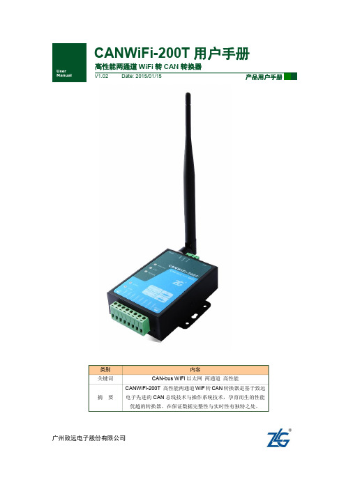
【用户手册】CANWIFI-200T高性能两通道WLAN转CAN转换器用户手册V1.02
CANDTU配置工具用户手册
广州致远电子股份有限公司CANDTU 配置工具CANDTU 设备配置工具修订历史目录1. 产品简介 (1)1.1硬件介绍 (1)1.2功能特点 (1)1.3配置和转换工具 (2)2. 配置工具 (4)2.1软件安装 (4)2.2驱动安装 (4)2.3整体界面 (7)2.3.1通用设置 (8)2.3.2CAN配置 (9)2.3.3过滤 (11)2.3.4触发器 (12)2.3.5数据转换器 (13)3. 数据转换工具 (17)4. 免责声明 (19)1. 产品简介1.1 硬件介绍在物联网逐渐普及的今天,CAN-bus总线作为一种有线的局域控制网络,有越来越多的客户需求进行远程监控。
比如车辆的CAN报文记录仪,以往只能在车返回后,才能读取行驶数据。
这样不能快速实时地监测到车辆的运行情况,做出及时的措施。
广州致远电子股份有限公司继研发成功CANREC——8通道CAN总线报文波形记录分析仪之后。
又推出了一系列带无线数据传输的CAN总线记录仪,不但可以离线CAN记录仪进行报文记录,还可以进行GPRS、3G等远程传输。
如图1.1所示。
图1.1 CANDTU系列CAN总线报文记录与无线数传设备1.2 功能特点∙2通道CAN数字信号记录通道;∙配置完成后,独立运行,最大支持32GB TF卡,用户可自行更换存储卡,两通道可同时工作,存储;∙CAN接口类型:高速CAN、容错CAN、单线CAN等(根据用户需要选配);∙记录报文时,能手动触发设备做时间标记,方便事后分析;∙记录报文时,可以按照用户需求设置触发条件,例如CAN ID作为触发条件等∙记录报文时,可以按照用户需求设置过滤条件,滤除无关报文∙报文记录,支持存储卡滚动记录或记满停止两种模式;∙记录报文支持全部存储、定时存储(可设置定时时间)∙文件导出可以设置文件大小、按ID排序等功能;∙内部时钟,带RTC纽扣电池,连接上位机后可以进行时间设置;∙选带以太网、GPRS或者3G无线通信,可以远程进行数据传输;∙无线数据传输支持每路CAN连接最多6个目标地址;∙无线数据传输支持全部传输、定时传输与按ID选择性传输;∙1通道USB接口,可以对设备进行配置;∙1通道以太网接口(部分型号没有)∙存储的数据格式可以导出ASC、DAT等格式数据,以便CANoe、INCA、CANScope分析;∙供电电压:9-36VDC(直流供电采用工业插座,保证稳固),可使用车载电源供电;∙工作温度: -25℃~+75℃;∙坚固耐摔,防尘、防高湿等汽车测试要求。
USR-CANET200 说明书

USR-CANET200说明书文件版本:V1.0.7功能特点⏹全新的硬件防护,CAN、串口、网口、电源均有高级别的防护,适合更苛刻的工业环境⏹全新ARM内核,工业级工作温度范围,精心优化的TCP/IP协议栈,稳定可靠⏹10/100Mbps网口,支持Auto-MDI/MDIX,交叉直连网线均可使用⏹支持CAN ID过滤功能,多种过滤方式使用起来更加安全方便⏹一个端口可支持两路SOCKET连接⏹CAN波特率支持10K~1Mbps;支持BASIC和LOOPBACK工作方式⏹支持静态IP地址或者DHCP自动获取IP地址,并可以通过UDP广播协议查询网络内的设备⏹Reload按键,一键恢复默认设置,不怕设置错⏹RJ45带Link/Data指示灯,网口外置隔离变压器,1.5KV电磁隔离⏹全球唯一MAC地址(D8-B0-4C开头)⏹支持通过网络升级固件,固件更新更方便⏹支持网页端口(默认80)更改⏹支持keepalive机制,可快速探查死连接等异常并快速重连⏹支持账户跟密码,可用于网页登录以及网络设置,更安全⏹电源接口支持5.08-2接线端子,支持宽电压供电(5~36V)⏹CAN中继功能⏹CAN转485功能目录USR-CANET200说明书 (1)1.快速入门 (5)1.1.硬件测试环境 (5)1.1.1.硬件准备 (5)1.1.2.硬件连接 (6)1.2.网络测试环境 (7)1.3.默认参数测试 (7)1.4.数据传输测试 (7)2.产品概述 (9)2.1.产品简介 (9)2.2.基本参数 (9)3.硬件参数介绍 (11)3.1.尺寸图 (11)4.产品功能 (12)4.1.网络基础功能介绍 (12)4.1.1.IP地址/子网掩码/网关 (12)4.1.2.DNS服务器地址 (13)4.1.3.恢复出厂设置功能 (14)4.1.4.WebServer (14)4.1.5.指示灯状态 (15)4.1.6.网络固件升级 (15)4.2.CAN (16)4.2.1.CAN基本参数 (16)4.2.2.CAN打包机制 (17)4.2.3.CAN ID过滤 (17)4.2.4.CAN数据透传协议 (17)4.3.串口功能 (19)4.3.1.串口基本参数 (19)4.3.2.串口成帧机制 (19)4.4.Socket功能 (20)4.4.1.TCP Client模式特性 (21)4.4.2.TCP Server模式特性 (21)4.4.3.UDP Client模式特性 (22)4.4.4.UDP Server模式特性 (22)4.5.特色功能 (23)4.5.1.心跳包功能 (23)4.5.2.注册包功能 (24)4.5.3.透传云功能 (25)4.5.4.CAN中继功能 (26)4.5.5.CAN转RS485功能 (27)5.参数设置 (29)5.1.设置软件 (29)5.1.1.功能介绍 (29)5.1.2.搜索 (29)5.1.3.查询和设置 (30)5.1.4.串口操作 (30)5.2.网页设置参数 (31)5.3.AT指令配置 (33)5.3.1.网络AT指令概述 (33)5.3.2.串口AT指令概述 (33)5.3.3.AT错误提示符 (34)5.3.4.AT指令集 (35)6.联系方式 (37)7.免责声明 (37)8.更新历史 (38)1.快速入门USR-CANET200模块用于实现串口到以太网口的数据的双向透明传输,用户无需关心具体细节,模块内部完成协议转换。
广成汽车USBCAN分析仪设备USBCAN-OBD 用户手册
USBCAN-OBD工业级USB-CAN转换器用户手册文档版本:V4.01(2017/01/13)修订历史版本日期原因V1.002013/6/16创建文档V2.012013/12/20修正设备工作参数V3.012015/04/22添加部分参数V3.502016/07/16添加OBDII功能V4.012017/01/13添加CANopen功能目录1.功能简介 (4)1.1功能概述 (4)1.2性能特点 (4)1.3典型应用 (5)2.设备安装 (6)2.1设备尺寸 (6)2.2接口定义及功能 (6)2.3驱动及软件安装 (7)3.设备使用 (8)3.1与PC连接 (8)3.2与CAN-bus连接 (8)3.3CAN总线终端电阻 (9)3.4系统状态指示灯 (10)4.ECANTools软件使用 (11)4.1软件启动 (11)4.2数据收发 (12)4.3总线分析功能 (12)4.4汽车数据解析功能 (13)4.5其他功能 (15)5.Linux系统使用说明 (16)6.二次开发 (19)7.技术规格 (20)8.常见问题 (21)附录1:CAN2.0B协议帧格式 (24)附录2:ISO15765协议数据与PID对应关系 (26)1.功能简介1.1功能概述USBCAN-OBD是集成1路CAN接口的便携式CAN-bus总线通讯接口卡。
该型号CAN卡是我公司专为汽车电子开发或汽车故障诊断用户设计,使用USBCAN-OBD便携式CAN接口卡,PC可以通过USB接口快速连接至汽车OBD 接口中的CAN-bus网络,使PC可以构成汽车CAN-bus网络中数据处理、数据采集的CAN-bus网络控制节点。
USBCAN-OBD便携式CAN接口卡是CAN-bus产品开发、CAN-bus数据分析的强大工具;同时具有体积小巧、即插即用等特点,也是便携式系统用户的最佳选择。
USBCAN-OBD接口卡上自带USB连接线缆,集成CAN接口电气隔离保护模块,使其避免由于瞬间过流/过压而对设备造成损坏,增强系统在恶劣环境中使用的可靠性。
DTU使用说明书

DTU使用说明书此说明书适用于下列型号产品:文档修订记录目录第一章产品简介 (3)1.1产品概述 (3)1.2 产品特点 (3)1.3工作原理框图 (4)1.4产品规格 (4)第二章安装 (8)2.1概述 (8)2.2 开箱 (8)2.3安装与电缆连接 (8)2.4电源说明 (11)2.5指示灯说明 (11)第三章参数配置 (12)3.1 配置连接 (12)3.2 参数配置方式介绍 (12)3.3 参数配置详细说明 (12)3.3.1 配置工具运行界面 (13)3.3.2 设备上电 (14)3.3.4 中心服务 (20)3.3.5 串口 (21)3.3.6 无线拔号 (22)3.3.7 全局参数 (23)3.3.8设备管理 (25)3.3.9其它功能项 (26)第四章数据传输试验环境测试 (26)4.1 试验环境网络结构 (26)4.2 测试步骤 (27)第一章产品简介1.1产品概述F2X16系列IP MODEM是一种物联网无线数据终端,利用公用蜂窝网络为用户提供无线长距离数据传输功能。
该产品采用高性能的工业级32位通信处理器和工业级无线模块,以嵌入式实时操作系统为软件支撑平台,同时提供RS232和RS485(或RS422)接口,可直接连接串口设备,实现数据透明传输功能;低功耗设计,最低功耗小于5mA@12VDC;提供1路ADC,2路I/O,可实现数字量输入输出、脉冲输出、模拟量输入、脉冲计数等功能。
该产品已广泛应用于物联网产业链中的M2M行业,如智能电网、智能交通、智能家居、金融、移动POS终端、供应链自动化、工业自动化、智能建筑、消防、公共安全、环境保护、气象、数字化医疗、遥感勘测、军事、空间探索、农业、林业、水务、煤矿、石化等领域。
IP MODEM典型应用如图 1-1 所示:图1-1IP MODEM应用拓扑图1.2 产品特点工业级应用设计◆ 采用高性能工业级无线模块◆ 采用高性能工业级32位通信处理器◆ 低功耗设计,支持多级休眠和唤醒模式,最大限度降低功耗◆ 采用金属外壳,保护等级IP30。
DTU V1.0使用手册
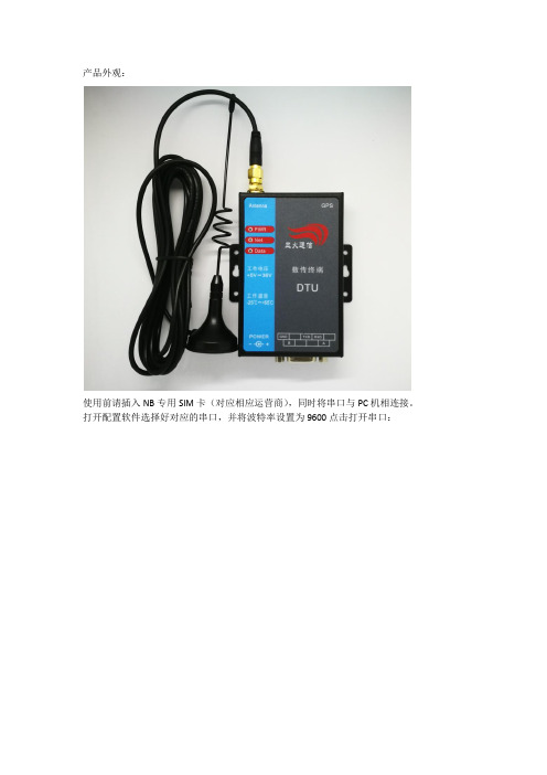
产品外观:
使用前请插入NB专用SIM卡(对应相应运营商),同时将串口与PC机相连接。
打开配置软件选择好对应的串口,并将波特率设置为9600点击打开串口:
然后接通电源,1-2s之后点击进入配置模式,选择服务器网络参数,填写需要的配置信息:
1.传输协议,选择UDP
2.服务器IP地址,选择您所需要上传数据的服务器IP地址
3.设备端口号,是设置设备连接的服务器的端口号。
参数设置好后,点击设置参数
设置好之后点击退出配置模式,关闭串口。
注意:进入配置模式需要在插电之后电源灯常亮,黄灯闪烁之前配置,否则配置不成功,需要重新插电操作。
NB-iot指示灯定义:
1、红灯:电源灯,长亮
2、黄灯:网络灯,长亮(没找到卡),慢闪(注册网络中),快闪(已经连接上服务器)
3、绿灯:数据等(发送数据的时候会快闪两下)。
DTU-200 说明
深圳市启天芯科技有限公司
内部机密 Page 9 of 9
管脚描述
序号 1 2 3
4
5 6 7 8
9
10 11
12
信号名称
I/O
VCC
P
GND
P
RXD
I
TXD
O
GND
P
RTS
I
CTS
O
TTL_RXD
I
TTL_ TXD
O
GND
P
TTL_DTR
I
TTL_RI
O
功能 供电 工作地 接收数据(控制器 ->DTU) 发送数据(DTU-> 控制器) 工作地 请求发送 清除发送 接收数据(控制器 ->DTU)
已注册到网 络 , IDLE 状 态
周期1
秒,高电
平持续
93.59 毫
秒
灭
周期3秒,
高电平持
续 93.59
毫秒
灯
CSQ<10 无SIM卡
灭
数据传输 故障指
指示
示灯
指 示 描 状态描 状态 述 述
灯 有 GPRS 规 附着 律 闪 烁
无 GPRS 灭 数据 传输
出现故 障,灯常 亮
DTU200_GPRS DTU Specification
电源指示
GSM网络指示灯 灯,D1
信号强度指
SIM卡指示 示灯
状态描述 指示状态 描述
指示状 态
描述
指示状态
描 述
块启动
持续高电 长亮 平
CSQ>20 以上
深睡眠状 态
持续低电 平或无信 号
较快
CSQ : 有SIM卡 10~20
USBCAN-E 2E-U 工业级高性能 CAN 接口卡 用户手册说明书
USBCAN-E/2E-U用户手册工业级高性能CAN 接口卡USBCAN-E/2E-U 用户手册修订历史USBCAN-E/2E-U 用户手册目录1. 功能简介 (1)1.1产品概述 ....................................................................................................................... 1 1.2 功能特点 ....................................................................................................................... 1 1.3 典型应用 .. (2)2. 设备安装 (3)2.1供电模式 ....................................................................................................................... 3 2.1.1 外部电源供电模式 ........................................................................................... 3 2.1.2 USB 总线供电模式 .............................................................................................. 3 2.2 CAN-bus 连接器 .......................................................................................................... 3 2.3 信号指示灯 . (4)2.3.1 USBCAN-E-U 信号指示灯 .................................................................................. 4 2.3.2 USBCAN-2E-U 信号指示灯 ................................................................................ 5 2.4 系统连接 .. (5)2.4.1 CAN 总线连接 ..................................................................................................... 5 2.4.2 总线终端电阻 ................................................................................................... 6 2.4.3 USB 总线连接 (6)3. 驱动程序 (7)3.1驱动安装 ....................................................................................................................... 7 3.2卸载设备驱动 (10)4. 常见问题................................................................................................................. 12 5. 检查和维护 ............................................................................................................. 15 6. 附录:CAN2.0B 协议帧格式 ............................................................................... 16 7. 免责声明 .. (18)USBCAN-E/2E-U 用户手册1.功能简介1.1 产品概述USBCAN-E/2E-U 高性能CAN 接口卡是与USB2.0总线全速规范兼容的,集成1~2路CAN 接口的高性能型CAN-bus 总线通讯接口卡。
CAN 记录仪使用手册说明书

诚至科技 简洁而不简单使用手册CAN 记录仪手册UM20230605 V2.02Date:2023/06/05CAN 记录仪使用手册类别 内容关键词 CANRecorder ,CANReplayer ,记录仪 摘 要CAN 记录仪、回放仪使用手册。
User Manual目录1. 适用范围 (1)2. 硬件介绍 (1)2.1设备外观 (1)2.2设备参数 (2)2.3设备接口定义 (2)2.4设备模式 (3)2.5固定挡板介绍 (6)2.6指示灯介绍 (7)3. 驱动安装 (7)4. CANBetter设置软件简介 (10)4.1软件概述 (10)5. CANRecorder(CAN记录仪模式)使用步骤 (12)5.1使用配置 (12)5.2CAN数据记录 (12)5.3CAN记录导出 (12)5.4CAN数据分析 (12)5.5利用CANoe分析数据 (13)5.6利用CANTracer软件分析 (13)6. 故障排查及注意事项 (14)6.1主要故障排查 (14)6.2注意事项 (15)7. 售后与保修 (16)8. 供货清单 (17)9. 免责声明 (17)1. 适用范围本公司的CANBetter系列产品包括:总线记录仪(又名为CanRecorder)、CAN总线数据回放仪(又名CanReplayer)、CAN总线网桥(又名为CanBridge)。
根据您所买的设备型号的不同,包含的功能可能有所不同。
请根据所选设备型号,参考相应功能介绍。
该设备包含两路独立CAN通道。
对于CanRecorder或CanReplayer,出厂默认配置8G~32G SD卡(根据客户购买时选择),用于记录CAN总线上收到的数据或回放数据。
典型应用■CAN-bus网络诊断与测试■汽车电子应用■电力通讯网络■工业控制设备■高速、大数据量通讯注意:下面所涉及设备图片、软件设置界面根据不同的产品型号可能会略有差异,请以实际设备型号为准。
DTU中英文操作手册
DTU V4 Release NoteDTU V4使用说明Date: 22/11/01Rotary LayeredDepth tracking display:井深跟踪显示:|----------------------------------------||* <ROTARY LAYERED> Rotary: 1573 ||Bit Depth: 1138.1 ft Block: STOP RESET|钻头进尺: 1138.1英尺堵塞:停止复位|REF Slips: IN Connection: 0.0 ft ||Hook Load: 75.1 psi SP: 1400 A) MENU||----------------------------------------|∙The flashing asterisk at the top left of the display indicates that setting/pulling slips detection is active.∙在左上角闪烁的星号表示使用放置/拖动卡瓦∙“Rotary:” – raw counts value from the rotary sensor (shaft encoder).∙“Rotary.”–旋转传感器(轴式编码器)所纪录的原始计数值∙“Block:” – current direction of travel of the travelling block – UP, DOWN or STOP. When the ROP is low the direction will not be shown continuously, it will alternate with …STOP‟.∙“Block.”–当前游动滑车的行进方向– UP(上),DOWN(下) 或 STOP(停止). 在机械钻速较低的情况下, 对该方向的显示是不连续的, 它将转换成“STOP”.∙“RESET” – indicates that a manual or automatic depth adjustment has been made and Orienteer has yet to acknowledge receipt of the reset.∙“RESET”–表明进行了手动或自动调整, 且定向软件此时才接收到复位信号∙“REF” – flashes to indicate that the draw works reference point (coil and layer) has not been set.∙“REF”–通过闪烁来表示还没对绞车的参考点(缆圈和层数)进行设置∙“Slips:” – IN, OUT, [IN] or [OUT]. Indicates whether the drill string is in or out of slips. When enclosed in square brackets the displayed bit depth should not be considered accurate. This occurs for a period of 7.5 seconds when setting or pulling slips.∙“Slip s.”– IN(内), OUT(外), [IN] 或[OUT]. 表示钻柱是在卡瓦内或卡瓦外. 当其被围在方形支撑架中时, 关于钻头深度的显示值是不精确的. 当放置或拖动卡瓦时, 这种情况会持续7.5秒钟.∙“Connection:” – when pulling slips the length of drill pipe added during the connection is calculated and displayed.∙“Connection.”–当拖动卡瓦时, 在计算和显示连接的过程中, 钻杆的长度以被加入∙“Hookload” – weight of string currently supported by the hook.∙“Hookload”(大钩载荷) –大钩当前所承受的钻柱的重量∙“SP” – hookload threshold for detection of setting/pulling slips. This is subject to a +-5% hysteresis. ∙“SP”–为了检测是否为放置/拖动卡瓦 , 而标出的大钩载荷的极限. 该值易受到一个+/-5%滞后作用Accurate depth tracking using rotary layered使用旋转层进的方法进行精确的深度跟踪To achieve accurate depth tracking the following steps must be followed:为了实现精确的深度跟踪, 请按以下步骤进行:a)Remove any existing correction factors 去掉所有现存的较正参数b)Setup draw works configuration 对绞车配置进行设定c)Set draw works reference point 设定绞车参考点d)Establish a hookload threshold setting 设定大钩载荷的极限值e)Set current bit depth 确定当前钻头深度f)Correct any errors present 更正当前存在的任何错误a)Remove existing correction factors去掉所有现存的较正参数From the main menu select “Depth Control” to access the depth control menu:在主菜单中选择” Depth Control”, 进入”深度控制”菜单|----------------------------------------||************<DEPTH CONTROL>*************| 其中: adjust bit depth –调整钻头深度|1) Adjust Bit Depth 4) Scaling Factor | reset bit depth –重置钻头深度|2) Reset Bit Depth 5) Connection Offset| set depth units –设定井深单位|3) Set Depth Units D) Exit| scaling factor –比例参数|----------------------------------------| connection offset –连接偏移exit –退出Select “Scaling Factor”. Set the scaling f actor to one.选择“Scaling Factor”. 设定该参数为1Select “Connection Offset”. Set the offset to zero.选择“Connection Offset”. 设定偏差为零b)Setup draw works configuration:对绞车配置进行设定To achieve accurate depth tracking it is essential that the draw works configuration is set up correctly. From the main menu select Calibrate Sensors. The calibrate menu contains four options:为了获得精确的深度跟踪, 非常有必要对绞车进行正确设定. 从主菜单中选择Calibrate Sensors. 在calibrate 菜单中包含4个选项|----------------------------------------|其中: draw works data –绞车数据|******<CALIBRATE: ROTARY LAYERED>*******| reference point –参考点|1) Draw Works Data 4) Factory Defaults| hookload sensor –大钩传感器|2) Reference Point | factory defaults –生产厂商默认值|3) Hookload Sensor D) Exit| exit –退出|----------------------------------------|Option 1) provides access to the configuration parameters that allow calculation of travelling block movement compensated for drum layering. Selection of option 1) displays the first half of the current draw works calibration:选项 1 ) 可以提供配置参数, 以便将游动滑车的移动补偿到滚筒层上. 选择选项1), 显示第一半关于当前游动滑车的标定值|----------------------------------------|其中: layer 1 coil length –第一层上一个线圈的长度|*********<VIEW DRAW WORKS DATA>*********| rope diameter –大绳的直径|Layer 1 coil length: 3.141ft A) Down| coils per layer –每一层上缆线的圈数|Rope diameter: 0.125ft C) Edit||Coils per layer: 36.00 to 36.00 D) Exit||----------------------------------------|Scrolling down using ‘A’ shows the remaining settings:按下“A”, 显示剩余设置|----------------------------------------|其中: lines in derrick –钻塔上的缆线数|*********<VIEW DRAW WORKS DATA>*********| counts per rev –每一次回转所进行的计数|Lines in derrick: 10 A) Up | counts INCREASE as blk goes UP –计数值随着滑|Counts per rev: 31 C) Edit| 车上移而增加|Counts INCREASE as blk goes UP D) Exit||----------------------------------------|To change any of these settings press ‘C’to reach the …Edit Draw Works Data‟ menu.若要改变这些值中的任意一个, 按下”C”, 进入”Edit Draw Works Data”菜单|----------------------------------------||*********<EDIT DRAW WORKS DATA>*********||1) Coils per Layer 4) Lines in Derrick||2) Rope Diameter 5) Rotary Sensor ||3) Layer 1 Coil Length D) Exit||----------------------------------------|See the section entitled …Edit Draw Works Data Menu’ for a full breakdown of the menu structure.察看这个标有”edit draw works data menu”的单元中细目分类1)Coils per Layer:The number of coils on each layer of the winch can be entered as a single value that applies to all layers or as individual values for each layer. If entered as individual values it is important that …Layer 1‟ corresponds to the layer whose coil length is used in option 3). Try to include part coils in this measurement for increased accuracy.指绞盘上每一层的缆绳圈数, 既可以将所有层设置为统一的一个值, 也可以对每一个层进行单独设置. 若要对每一个层进行单独设置, 则一定要注意, “layer 1”与在选项3) 中使用的缆圈所处的层相一致. 为了提高精度, 可以试着在此次测量中包含部分缆圈.2)Rope DiameterDiameter of the rope should be measured either using callipers or by wrapping a piece of string around the rope by a number of complete turns, measuring the length and using the following formula:可以使用测径规测量大绳的直径. 或将一截绳子缠绕在大绳上, 数出完整的圈数, 并该圈数的绳子所对应的长度, 然后通过以下公式计算大绳的直径Rope Diameter = length / turns / PI大绳直径= 长度/圈数/pi3)Layer 1 coil length 第一层的线圈长度This is the length of one coil on the first (bottom) layer of rope on the drum. If the bottom layer is not accessible for measurement then the layer treated as layer 1 should be the lowest layer that is ever used, ie the layer that is partially unwrapped when the travelling block is at its lowest possible position. It is very important that the layer chosen will never be fully unwound from the drum.The length should be measured by marking two adjacent coils with chalk, spooling those coils off the drum and measuring the distance between the two chalk marks. If this is not possible and the actual drum diameter is known the layer 1 coil length can be calculated as follows:这是指在缆盘最底部那一层一圈缆绳的长度. 如果无法对最底层缆绳进行测量, 那么将使用过的缆绳中处于最底层的那一层作为第一层. 例如: 当滑动绞车位于其最低位置时, 大绳被部分松开的那一层. 必须注意的是, 所选的那一层永远不会完全从缆盘上被松开. 用粉笔在两个相邻的线圈之间进行标注, 将这些线圈从缆盘上松开, 测量这两个标志之间的距离. 如果无法完成上述过程, 且实际的缆盘直径已知, 那么第一层的线圈长度可以通过以下公式进行计算:Layer 1 coil length = (drum diameter + rope diameter) * PI层1 缆圈的长度= (缆盘直径+大绳直径)*piMeasuring the distance between the two adjacent chalk marks can be achieved by using adhesive tape to secure a tape measure at the first chalk mark then lowering the travelling block until the second chalk mark is just off the drum.对相邻两个标记间距离的测量可以通过以下方式实现: 用粘性胶带将一个皮尺固定在第一个标志处, 然后使绞车向下移, 直到第二个标记刚刚脱离缆盘为止.4)Lines in derrickThis is the total number of lines running between the travelling block and the crown block, ie:这是指在滑动绞车和定滑轮之间的总缆线数. 例如:Lines in derrick = Number of sheaves in travelling block * 2钻塔上的缆线数=在绞车上的线数*25)Rotary Sensor 旋转传感器|----------------------------------------||*******<ENTER ROTARY SENSOR DATA>*******|其中:counts per rev –每一转所计树值|1) Counts per Rev | select direction –方向的选择|2) Select Direction || D) Exit||----------------------------------------|1)Counts per RevIf this is not known it can be measured by marking the position of the central (rotating) part ofthe sensor relative to the outer (stationary) part then rotating the sensor through exactly one full turn while observing the rotary counts display on the main depth tracking display. Because the DTU senses both the rising and falling edges of the rotary sensor output signal the valuerequired may be double the manufacturer‟s quoted figure.在为止的情况下, 可通过以下方法进行测量: 将传感器上相对于外部(固定部分)的中心部位标注出来, 然后将传感器完整的旋转一圈, 观察在深度跟踪主页面上显示的旋转计数值.由于DTU传感器能够感应旋转传感器输出信号的上跳沿和下跳沿, 则所需的数值也许是生产商所提供数值的两倍2)Select directionDepending on the orientation of the rotary sensor on the draw works drum the raw count valuefrom the sensor increase either when the travelling block moves up or down. The simplest way to establish whether this setting is correct is to observe the block travel direction indicator onthe main depth tracking display while the block is in motion. If this is incorrect then select theopposite direction setting.传感器中原始的计数值会随着绞车的上移或下移而增加, 这取决于在绞盘上的传感器的方向. 确定该设定是否正确的最简单的方法是, 在绞车运动的情况下,检查深度跟踪主页面上所显示的绞车的移动方向. 如果该设定是不正确的, 则设置为相反的方向.c) Set Draw Works Reference Point 设置绞车参考点In order that the DTU can use the layering data correctly it must know the current layer and coil position on the draw works. From the Calibration menu select …Reference Point‟:DTU必须要知道当前层和绞车上线圈的位置, 以使其能够正确利用缆层数据. 在Calibration菜单中选择…Reference Point‟|----------------------------------------||******<DRAW WORKS REFERENCE POINT>******||Reference: Layer: 1 Coil: 5.00 || Current: Layer: 2 Coil: 19.74 ||1) Set new reference point D) Exit||----------------------------------------|The display shows any previously entered reference point (…Reference‟) and the layer/coil pos ition that the DTU thinks the draw works is currently at (…Current‟). If the current position is not correct, ie the actual number of layers and coils that can be seen to be on the draw works drum by visual inspection does not match the values displayed as …Current‟ then 1) Set new reference point should be selected and the actual values entered. Note that the reference point must be updated when the drill line is cut and slipped.这里显示了任意一个事先输入的参考点(“reference”)以及DTU所认为的当前绞车所在的线缆层/缆圈的位置. (“Current”). 如果当前位置不正确, 例如: 用眼睛所看到的在缆盘上的缆层和缆圈数与”current”所显示的不符, 那么 1)选择”set new reference point”(设置新的参考点), 并输入实际值.注意: 如果钢丝绳断并打滑时,必须重新输入参考点.d) Establish the hookload threshold setting (Set Point) 确定大钩载荷极限(参考点)Record the maximum hookload value when the string is in slips. If possible observe the hookload during both rotary drilling and sliding and record the minimum hookload value while out of slips. From the main menu select “Hookload Set Point” and enter a value that is roughly half way between the two values recorded当钻柱在卡瓦中时, 记录下最大大钩负载值. 如果可能的话, 在旋转钻进和滑钻时观察大钩负载,在钻柱脱离卡瓦时, 记录下大钩负载的最小值.e) Set current bit depth 设置当前的钻头深度From the …Depth Control‟ menu select …Reset Bit Depth‟. Enter the current actual bit depth.在”depth control”菜单中选择”reset bit depth”(重新设置钻头深度). 输入当前钻头的实际深度.f) Correct any errors present 对任何存在的误差进行纠正Typically there will be some error present in the draw works data entered. There may additionally be errors present in the automatic pulling/setting slips detection. To fine tune the depth tracking and reduce the frequency at which manual depth resets must be performed follow this procedure:通常, 在输入绞车数据时会存在一些误差. 另外, 在自动检测拖拉/放置卡瓦方面也有可能存在误差. 为了很好的进行深度跟踪并减少手动设定深度的次数, 按照以下步骤进行:1)Observe a connection being made using a section of drill pipe whose length is known accurately. Itis best if you can measure the length yourself rather than relying on the driller‟s pipe tally.使用一段已知实际长度的钻管作为连接部件. 最好亲自量一下钻管的长度,而不是仅依赖于钻管标签上标注的长度2)Record the …Connection‟ length displayed on the depth tracking display once the connection iscomplete, ie the drill string is out of slips. We will call this the “DTU connection length”.一旦完成连接, 记录下显示在深度跟踪屏幕上的”connection”长度. 例如: 钻柱脱离卡瓦. 我们称此为”DTU连接长度”3)Lower the string until the bottom shoulder joint of the piece of drill pipe that has just beenconnected is exactly level with some reference point (for instance the rotary table).向下放钻柱, 直到被连接钻管的底端接头端面与某些参考点(例如: 转盘) 绝对水平.4)Record the bit depth. 记录下钻头深度5)Lower the string until the top shoulder is level with the reference point.向下放钻柱, 直到顶部端面与参考点水平.6)Record the bit depth. 记录下当前钻头深度7)Subtract the smaller of the two recorded depth values from the larger value. We will call this the…DTU depth change‟.在记录下的两个深度值后, 用较大的那个值减去较小的那个值. 我们称这个值为”DTU深度变化值”.The difference between the two recorded depths should now equal the length of the pipe connected. If it does not then there is an error in the draw works data entered. If the error is very large it would be best to repeat the procedure from a). If the error is reasonably small calculate a scaling factor as follows:这两个值之差应当与连接钻管的长度相同. 如果不同, 那么输入的绞车数据存在误差. 如果这个误差很大, 最好从a) 重新进行. 如果误差相对较小, 按如下公式计算比例因子:Scale factor = length of drill pipe / DTU depth change比例因子= 钻管的长度/DTU深度变化Now correct for any slips detection error:现在, 对任何卡瓦检测误差进行纠正:Connection Offset = length of drill pipe – (DTU connection length * scale factor)连接偏差=钻管的长度– (DTU连接长度*比例因子)8)Enter the scale factor and connection offset via the “Depth Control” menu.在”Depth Control”菜单中输入比例因子和连接偏差9)Reset the bit depth to the current bit depth.将钻头深度设置为当前钻头深度NOTE: If a connection offset of greater than 1 inch (2.54cm) is entered the DTU will flag a depth reset to Orienteer at the end of each connection.. The connection offset will only be applied if the connection is greater than 9‟ 10” (3 metres).注意: 如果输入的连接偏差大于1英寸(2.54厘米), 那么DTU将在每一处连接的尾端相Orienteer 软件重新设定一个深度标志. 只有在连接长度大于9‟10”(3米)时才使用连接偏差.Rotary Layered Menu Structure 菜单结构Main Menu: 主菜单|----------------------------------------||**************<MAIN MENU>***************||1) Hookload Set Point 4) Depth Control||2) Depth Tracking Mode 5) Test Mode ||3) Calibrate Sensors D) Exit||----------------------------------------||----------------------------------------||**********<HOOKLOAD SET POINT>**********|=> 1)| Current hookload: 73.7 psi A) Ok ||Current set point: 1399.8 psi C) Clear|| New set point: [ ]psi D) Abort||----------------------------------------||----------------------------------------||*************<SELECT MODE>**************|=> 2)|1) Rotary Standard ||2) Rotary Layered <=== A) Ok ||3) Water Bottle D) Abort||----------------------------------------||----------------------------------------||******<CALIBRATE: ROTARY LAYERED>*******|=> 3)|1) Draw Works Data 4) Factory Defaults| ===> Calibrate Menu|2) Reference Point | 校订菜单|3) Hookload Sensor D) Exit||----------------------------------------||----------------------------------------||************<DEPTH CONTROL>*************|=> 4)|1) Adjust Bit Depth 4) Scaling Factor | ===> Depth Control Menu|2) Reset Bit Depth 5) Connection Offset| 深度控制菜单|3) Set Depth Units D) Exit||----------------------------------------||----------------------------------------||****<TEST MODE MENU: ROTARY LAYERED>****|=> 5)|1) Raw Data | ===> Test Mode Menu|2) Firmware Info | 检测模式菜单|3) Draw Works Position D) Exit||----------------------------------------|Calibrate Menu: 校验菜单|----------------------------------------||******<CALIBRATE: ROTARY LAYERED>*******||1) Draw Works Data 4) Factory Defaults||2) Reference Point ||3) Hookload Sensor D) Exit||----------------------------------------||----------------------------------------||*********<VIEW DRAW WORKS DATA>*********|=> 1)|Layer 1 coil length: 3.141ft A) Down||Rope diameter: 0.125ft C) Edit||Coils per layer: 36.00 to 36.00 D) Exit||----------------------------------------||----------------------------------------||*********<VIEW DRAW WORKS DATA>*********|=> Down |Lines in derrick: 10 A) Up ||Counts per rev: 31 C) Edit||Counts INCREASE as blk goes UP D) Exit||----------------------------------------||----------------------------------------||*********<EDIT DRAW WORKS DATA>*********|=> Edit |1) Coils per Layer 4) Lines in Derrick| ===> Edit Draw Works Data Menu |2) Rope Diameter 5) RotarySensor | 大钩数据编辑菜单|3) Layer 1 Coil Length D) Exit||----------------------------------------||----------------------------------------||******<DRAW WORKS REFERENCE POINT>******|=> 2)|Reference: Layer: 1 Coil: 5.00 || Current: Layer: 2 Coil: 19.74 ||1) Set new reference point D) Exit||----------------------------------------||----------------------------------------||****<SET DRAW WORKS REFERENCE POINT>****|=> 1) | A) Ok ||Enter current layer:[1 ] C) Clear||Max: 20 Min: 1 D) Abort||----------------------------------------||----------------------------------------||****<SET DRAW WORKS REFERENCE POINT>****|=> Ok| A) Ok ||Enter current coil:[15 ] C) Clear||Max: 150.00 Min: 0.00 D) Abort||----------------------------------------||******<VIEW HOOKLOAD SENSOR DATA>*******|=> 3)|Pressure at 4ma: 0.000 psi | ===>Edit Hookload Sensor Data Menu|Pressure at 20ma: 1450.0 psi C) Edit|| D) Exit||----------------------------------------|Resetting factory defaults will reset all calibration data entered by the operator. This optionshould therefore be used with caution.对生产商所设定的默认值进行重设定将会把操作人员所输入的所有标定数据进行重置.因此, 使用此操作应十分小心.|----------------------------------------||*******<RESTORE FACTORY DEFAULTS>*******|=> 4) |Restoring factory defaults will ||erase ALL calibration data for A) Ok ||ALL modes. Proceed? D) Abort||----------------------------------------|Depth Control Menu: 深度控制菜单|----------------------------------------||************<DEPTH CONTROL>*************||1) Adjust Bit Depth 4) Scaling Factor ||2) Reset Bit Depth 5) Connection Offset||3) Set Depth Units D) Exit||----------------------------------------||----------------------------------------||***********<ADJUST BIT DEPTH>***********|=> 1)|Current depth: 1137.57 ft A) Ok ||New bit depth: 1138.07 ft B)+ C)-|| Change:[ +0.50]ft D) Abort||----------------------------------------||----------------------------------------||***********<RESET BIT DEPTH>************|=> 2)|Current depth: 1138.07 ft A) Ok ||New bit depth:[ ]ft C) Clear|| D) Abort||----------------------------------------||----------------------------------------||***********<SET DEPTH UNITS>************|=> 3)|1) Metres ||2) Feet <=== A) Ok || D) Abort||----------------------------------------||----------------------------------------||*********<EDIT SCALING FACTOR>**********|=> 4)|Current scale factor: 1.000 A) Ok || New scale factor: [ ] C) Clear||Max: 10.00 Min: 0.01 D) Abort||----------------------------------------||********<EDIT CONNECTION OFFSET>********|=> 5)|Current offset: 10.000 ft A) Ok || New offset: [ ]ft C) Clear||Max: 49.21 Min: -49.21 B) Neg D) Abort||----------------------------------------|Test Mode Menu: 检测模式菜单|----------------------------------------||****<TEST MODE MENU: ROTARY LAYERED>****||1) Raw Data ||2) Firmware Info 5) Hardware Tests||3) Draw Works Position D) Exit||----------------------------------------|Displays raw data from the sensors. Hookload is displayed in volts where 0.48v = 4ma and 2.4v = 20ma.显示传感器测得的原始数据. 大钩负载是以电压的形式表示的, 其中0.48伏=4毫安, 2.4伏=20毫安|----------------------------------------||******<TEST MODE: ROTARY LAYERED>*******|检测模式: 旋转缆层式=> 1)| Now Min Max ||Hkld: 0.58v 0.58v 0.58v B) Reset||Rot: 1573 1573 1573 D) Exit ||----------------------------------------||----------------------------------------||*********<FIRMWARE INFORMATION>*********|软件版本信息=> 2)|Orienteer DTU V4.00 ||Code space checksum: EC4E || D) Exit||----------------------------------------|Displays current layer and coil as calculated from the draw works data and reference point.显示通过计算绞车数据和参考点而得到的当前缆层和缆圈|----------------------------------------||*********<DRAW WORKS POSITION>**********|绞车位置=> 3)|Counts: 1573 ||Layer: 1 Coil: 15.00 ||Block: STOP D) Exit||----------------------------------------||----------------------------------------||************<HARDWARE TESTS>************|硬盘检测=> 5)|1) Test Keypad ||2) Test LCD Display || D) Exit||----------------------------------------||----------------------------------------|| ************<KEYPAD TEST>**************|键盘检测=> 1)| Press 'D' twice to exit. || || Key: ||----------------------------------------||----------------------------------------||***********<LCD DISPLAY TEST>***********|液晶显示检测=> 2)| ||Press a key to fill display |按任意键进行满屏显示|Press 'D' twice to exit |按两下”D”, 以退出|----------------------------------------|Edit Draw Works Data Menu: 绞车数据编辑菜单Allows viewing and entry of the draw works data required for accurate depth tracking为了精确跟踪深度, 允许检查和输入绞车的设定值|----------------------------------------||*********<EDIT DRAW WORKS DATA>*********||1) Coils per Layer 4) Lines in Derrick||2) Rope Diameter 5) Rotary Sensor ||3) Layer 1 Coil Length D) Exit||----------------------------------------||----------------------------------------||*********<EDIT COILS PER LAYER>*********|=> 1)|1) Enter one value for all layers ||2) Edit individual layers || D) Exit||----------------------------------------||----------------------------------------||*********<EDIT COILS PER LAYER>*********|=> 1)| A) Ok ||Enter coils per layer:[ ] C) Clear||Max: 150.00 Min: 5.00 D) Abort||----------------------------------------||----------------------------------------||*********<SELECT LAYER TO EDIT>*********|=> 2)|Layer 1: 36.00 coils <=== A)- B)+||Layer 2: 36.00 coils C) Edit||Layer 3: 36.00 coils D) Exit||----------------------------------------||----------------------------------------||*********<EDIT DRAW WORKS DATA>*********|=> 2)| A) Ok ||Enter rope diameter:[ ]ft C) Clear||Max: 0.656ft Min: 0.016ft D) Abort||----------------------------------------||----------------------------------------||*********<EDIT DRAW WORKS DATA>*********|=> 3)|Layer 1 coil length: A) Ok ||[ ]ft C) Clear||Max: 16.404ft Min: 0.328ft D) Abort||----------------------------------------||----------------------------------------||*********<EDIT DRAW WORKS DATA>*********|=> 4)| A) Ok ||Enter lines in derrick:[ ] C) Clear||Max: 40 Min: 1 D) Abort||----------------------------------------||----------------------------------------||*******<ENTER ROTARY SENSOR DATA>*******|=> 5)|1) Counts per Rev ||2) Select Direction || D) Exit||----------------------------------------||----------------------------------------||*******<ENTER ROTARY SENSOR DATA>*******|=> 1)| A) Ok ||Enter counts per rev:[ ] C) Clear||Max: 999 Min: 2 D) Abort||----------------------------------------||----------------------------------------||****<SELECT ROTARY SENSOR DIRECTION>****|=> 2)|Counts increase when: ||1) Block goes UP <=== A) Ok ||2) Block goes DOWN D) Abort||----------------------------------------|Edit Hookload Sensor Data Menu: 编辑大钩传感器数据Allows the hookload sensor scaling to be set so that the actual pressure seen by the sensor is shown on the main display. Correct hookload sensor scaling is not required for correct operation of the DTU.允许设定大钩传感器比例, 这样, 传感器感应的实际压力便可以在主屏幕上进行显示. 正确操作DTU时, 不需要校正大钩传感器比例.|----------------------------------------||******<VIEW HOOKLOAD SENSOR DATA>*******|察看大钩传感器数据|Pressure at 4ma: 0.000 psi ||Pressure at 20ma: 1450.0 psi C) Edit|| D) Exit||----------------------------------------||----------------------------------------||******<EDIT HOOKLOAD SENSOR DATA>*******|编辑大钩传感器数据=> Edit|1) Pressure at 4ma ||2) Pressure at 20ma || D) Exit||----------------------------------------||----------------------------------------||******<EDIT HOOKLOAD SENSOR DATA>*******|=> 1)| A) Ok ||Enter psi at 4ma:[ ]psi C) Clear|| D) Abort||----------------------------------------||----------------------------------------||----------------------------------------||******<EDIT HOOKLOAD SENSOR DATA>*******|=> 2)| A) Ok | |Enter psi at 20ma:[ ]psi C) Clear|| D) Abort|。
【用户手册】DTU配置AT命令
3.25 调试信息(DBGINF) ..........................................................................................12
3.26 CDMA 信号强度(CSQ) ....................................................................................12
3.27 显示帮助信息(HELP).......................................................................................12
3.28 复位 DTU 模块(RSTDTU) ...............................................................................12
3.18 心跳包数据设置(BEATDATA)......................................................................... 11
3.19 帧间隔时间和数据包最大长度(SERS,MTU)............................................... 11
3.31 选择启动固件(BOOT) ......................................................................................12
3.32 显示当前设置内容(SETLIST) .........................................................................12
CAN使用手册

CANopen旋转编码器使用说明书内容提要1.注意事项2.标识3.安装4.电气连接5.CANopen 接口6.参数设置7.附件1 注意事项电气安装时应注意以下几个方面:-编码器尽可能地靠近控制单元安装。
-尽可能的使用有屏蔽的双绞线。
-避免信号线靠近高压电缆(例如驱动电缆等)。
-如果需要可以对编码器电源安装EMC 滤波器。
-避免编码器安装在容性性噪声源或开关电源附近。
连接请参考第4 章: "电气连接"。
2 标识设备信息可以通过产品标签上的型号,产品序列号获知。
3 安装。
4 电气连接4.1 CANopen 接线定义连。
4.2 总线终端当编码器为CAN 网络上的最后一个设备时,需要将终端电阻Rt 拨码开关 拨到“ON ”状态。
或感安装时请确保编码器的防护等级符合要求。
避免敲打、撞击、腐蚀编码器4.3 波特率设置:DIP A波特率既可以通过硬件模式设置,也可以通过软件模式设置。
如果DIP A 第4位=OFF 则比特率由对象字典的3000h 来定义,可以通过SDO 报 文进行修改。
如果DIP A 第4 位=ON ,则比特率可由拨码开关 DIP A 进行设置。
由拨码开关设置波特率时,请先关闭掉设备。
波特率可由拨码开关的二进 制状态进行表示(ON 代表1,OFF 代表0)。
拨码开关与波特率对照表例如:设置波特率为250 Kbit/s ,查表可知拨码开关的编码为100,第4位设为ON 。
设置波特率为500 Kbit/s ,查表可知拨码开关的编码为101,第4位设为ON 。
位202122ON/OFF1234位12342012ON FF22/O FF O ONON1234位20122 2ONFFO ONONFF O4.4 节点号设置拨码开关:DIP B编码器的节点号,既可以通过硬件模式设置,也可以由软件模式进行设置,范围 1 至127 之间节点号由数据01h 文进行修改。
如果DIP B 则节点号由DIP B 来定义。
汽车行驶记录仪使用说明书
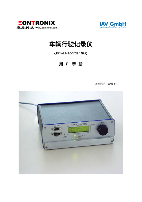
车辆行驶记录仪(Drive Recorder NG)用 户 手 册发布日期:2006-6-1Drive Recorder NG声明本用户手册仅用于意昂科技为客户提供培训之用。
由于翻译水平有限,其中难免有些内容与英文原版Operating Manual有所偏差,还望读者不吝批评指正。
偏差之处,请以“Operating Manual” Version dated 24.11.2003 对应内容为准。
为了便于读者阅读和对比参考,本手册章节编排与“Operating Manual” Version dated 24.11.2003 保持一致。
目录1 简述 (1)1.1 Drive Recorder NG系统-简述 (1)1.2 基本操作流程 (2)2 测量准备 (2)2.1 PC系统要求 (2)2.2 存储卡驱动安装 (2)2.3 安装软件包 (2)3 Drive Recorder (3)3.1 Drive Recorder-前面板 (3)3.2 Drive Recorder-后面板 (3)3.3 Drive Recorder菜单-结构和方位 (4)3.3.1 主菜单-结构 (4)3.3.1.1 设备状态(第1行) (4)3.3.1.2 测量状态(第2行) (4)3.3.2 子菜单 (5)3.3.2.1 测量子菜单 (5)3.3.2.2 系统子菜单 (5)3.3.2.3 专家子菜单 (6)3.3.2.4 故障子菜单 (6)3.3.2.5 高级用户子菜单 (6)3.4 Flash卡格式化 (6)3.5 固件升级 (6)3.6 错误显示 (6)3.7 关闭电源 (6)3.8 触发前测量 (7)3.9 触发后测量 (7)3.10 LED指示灯 (7)3.10.1 Slot LED (7)3.10.2 状态LED (7)3.10.3 手动触发LED (7)4 配置软件 (7)4.1 简述 (7)4.1.1 菜单 (8)4.1.1.1 编辑菜单 (8)4.1.1.2 选项菜单 (10)4.1.1.3 帮助菜单 (11)4.1.2 工具栏 (11)4.2 接口选项 (11)4.2.1 A/D(Analogue/Digital)项 (11)4.2.2 CAN项 (11)4.2.2.1 载入描述文件 (11)4.2.2.2 信号多路技术 (12)4.2.2.3 硬件参数浏览 (13)4.2.3 K-Line项 (13)4.2.3.1 载入描述文件 (13)4.2.3.3 KWP2000协议参数 (14)4.2.3.4 McMess协议参数 (14)4.3 配置测量任务 (14)4.3.2 记录数据 (15)4.3.2.1 Ring Buff记录模式 (15)4.3.2.2 触发操作模式 (15)4.3.3 Global 项 (15)4.3.4 Event 项 (15)4.3.5 CAN Log项 (16)4.3.6 记录数字输入状态 (17)4.3.7 测量设置 (17)4.3.7.1 激活/失效一个测量组 (17)4.3.7.2 激活一个ring buffer (17)4.3.7.3 Fast measurement模式/constant rate 模式 (18)4.3.7.4 储存模式 (18)4.3.7.5 测量序列 (19)4.3.8 编辑触发条件 (19)4.3.8.1 定义一个常量 (21)4.3.8.2 定义timeout (21)4.3.8.3 编辑条件 (21)4.3.8.4 定义flags (23)4.3.8.6 触发条件 (23)4.3.8.7 当事件触发一个测量序列后启动Post-trigger (24)4.3.9 保存配置文件/初始化测量运行 (24)5 转化软件 (25)5.1 载入读数 (25)5.2 可能的设置 (26)5.3 选择并转化测量序列 (27)5.4 设置菜单 (27)5.5 MDF time stamp的测量精度 (28)6 在线数据显示 (28)6.1 建立通信 (30)6.2 加载配置文件 (30)6.3 选择通道 (32)6.4 设置 (33)6.5 其他程序菜单 (33)6.5.1 Communication菜单 (33)6.5.2 Help 菜单 (34)6.5.3 工具栏 (34)1 简述Drive Recorder 是一款功能强大的测试系统,它用来进行耐久性试验,已经被指定为车载电控系统的专用测试设备。
DTU Data Transfer Utilities 软件用户手册说明书

DTUData Transfer Utilities SoftwareUser manualFt. Atkinson, Wisconsin USAPanningen, NederlandD3912-GB Rev A Sept 11Table of contentsTABLE OF CONTENTSDTU Software general (1)Minimum System Requirements (1)Install Software: (2)Data Transfer Utilities (3)Main screen (3)Explanaition of butons (3)Settings (4)System settings (4)Language (5)Help (5)DataKey operations (6)Read/View DataKey (6)Make DataKey (7)DDL operations (8)Read/View DDL (8)Mem Card operations (9)Read Mem Card (9)Streaming Data (10)Sending Information (11)Scale Emulator (12)All rights reserved. Reproduction of any part of this manual in any form whatsoever without Digi-Star’s express written permission is forbidden. The contents of this manual are subject to change without notice. All efforts have been made to assure the accuracy of the contents of this manual. However, should any errors be detected, Digi-Star would greatly appreciate being informed of them. The above notwithstanding, Digi-Star can assume no responsibility for any errors in this manual or their consequence.© Copyright! 2011 Digi-Star, Fort Atkinson (U.S.A.).DTU Software generalThe DTU software allows you to send data from your Digi-Star indicator to your PC. The DTU software can work with all Digi-Star communication devices (DataKey, DDL module and Memory Card). It also allows you to connect your indicator directly to you PC and receive streaming data or send commands.Follow the installation instruction on Page: 2. Select the communication device that you use and follow the manual instructions. Check the indicator manual for the data and print formats that you can send to your PC.Minimum System RequirementsMake certain that your system includes the following hardware and software. These arethe minimum system requirements to run DTU• A Pentium 100 or better PC•Microsoft Windows 95/98 and higher•100 Meg Free disk space•32 Meg Ram•CD Drive• A serial port*/USB to serial Adapter•Printer•Internet connectionInstall Software:1. Insert the DTU CD into your CD-ROM drive.2. From your Windows start menu, select RUN.3. Select BROWSE on your CD drive, select Setup.exe.4. Click Open.5. Click OK.6. Follow the installation prompts from the software.Data Transfer Utilities Main screenExplanaition of butons- All DataKey functions- All DDL functions- All Mem Card function- Streaming data- Scale Data logger- Scale emulator- Help menuSettingsSystem settings•Com Port Settings: This is the pre-defined port. Choose “Auto Find” to automatically find the Com Port the device is connected to.•File Location: This is the default location on your PC where the data will be saved•File Type: This is the default file type.•Preferred Hardware: Select the hardware device that you use. Check the “Filter Hardware”box to only show the selected hardware device on the main screenLanguage•Select desired languageHelp•About: shows software version information•Check for updates: Check on line for available updates •Digi-Star EZ connect: For on line support•Visit Digi-Star on the web: Go to Digi-Star web site•DTU Help: View help filesDataKey operationsThe DataKey can be used for sending and receiving feeding and group data to your Digi-StarEZ3600V and EZ4600 indicators.•Clear DataKey: Delete all data from DataKey•DataKey status: This will get the current status of a Digi-Star DataKey that is connected to your PC via a Docking StationRead/View DataKeyo Click the arrows button to retrieve the information from the Digi-Star DataKeyo Click the Save button to save what is on-screen.o Click the Delete button to delete what is on-screen.Make DataKeyo Choose the Feeding Mode that you want to feed in. (list or Loads mode)o Choose the Feeding number.o Enter the Recipes – enter all ingredients of each recipeo Enter the groups you want to feedo Check the Recipe that you want to send to the DataKeyo Check the Group(s) that you want fed that recipe to.o Click theo Click the button to send the Feed lines to a Digi-Star DataKeyo Click the button to send the Feed lines to a USBo Click the to Save the Feed lines to your PCo Click the to load in Feed lines that were previously saved to your PC•Authorize DataKey: Authorize DataKey (Contact you dealer before using this function) •Test DataKey: Test DataKeyDDL operationsThe DDL can be used for transferring weight, feeding, field and other information from the Digi-Star GT400, EZ2400V and EZ3400V indicators to a PC.Check the indicator manual for the available data print formats.Note: In order to store data from the indicator to the DDL, the DDL module has to be connected to the serial port of your indicator at any time. The indicators mentioned above have NO internal memory so without the DDL installed no data will be stored.Use the in the DDL kit included serial cable (and if required USB converter) to connect DDL module to PC.Read/View DDLo Click to Read the DDLo Click to Save what is on screeno Click to Delete what is on screen•Clear DDL: Delete all data from DDL•Test DDL: Test DDLMem Card operationsFor use with the Tyrell feeding system.Read Mem Card•Click to Read the Mem Card•Click to Save what is on screen•Click to Delete what is on screenStreaming DataThe Streaming Data screen is designed to send and receive information through a RS232 connection and display/save that information.•Step 1 – Set the Communication Port•Step 2 – Start/Open the Communication Port by clickingo Click the button to pause the process.o Information will be displayed in:o You can click the Save button to save and the Delete button to clear this area.o You can also select following to filter the results•Information is also displayed aso Trace will “turn on” and “turn off” this window.o Decimal/Hex Based: when your mouse “hovers” over an item, an automatic window will display the value.o Time Recorded: displays how long you have been Sending/Receiving informationo You also have the ability to Save/Print in many formats using the buttons on the right.Sending Information•EZ1 Commands: Listing of all Digi-Star EZ1 commands•EZ2 Commands: Listing of several of the Digi-Star EZ2 Commands•Custom Command: Ability for you to build/send any command•Run Scripts: Ability to read in a Text file that contains a list of commands and send them out one at a time.•Simulation: Ability to read in a Text file that contains a list of commands and send them ata specific frequency.Scale EmulatorThe scale emulator allows you to view the selected indicator by selecting indicator and com port.o Press close to exit.。