公牛牌电子式定时器说明书
可编程多功能电子定时器使用说明书CX-T0203

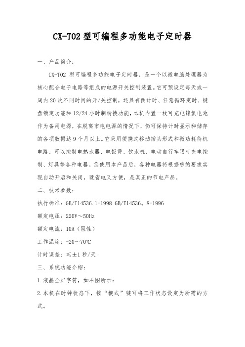
CX-T02型、CX-T03型可编程多功能电子定时器使用说明书一、产品简介:CX-T02型、CX-T03型可编程多功能电子定时器,是一个以微电脑处理器为核心配合电子电路等组成的电源开关控制装置。
它可预设定每天或一周内20次不同时间的开/关控制,还具有倒计时、任意循环定时、键盘锁定功能和12/24小时制转换功能。
本机内置一枚可充电镍氢电池作为备用电源,在脱离市电电源的情况下,仍可保持计时显示和储存的各项数据达9个月以上。
它采用便携式移动插头形式和微功耗待机电路,可以控制电热水器、电饭煲、饮水机、电动自行车限时充电控制、灯具等各种电器。
您使用本产品后,各种电器将根据您的要求实现自动开启和关闭,既省电又方便,是真正的节电产品。
二、技术参数:执行标准:GB/T14536.1-1998 GB/T14536.8-1996额定电压:220V ~50Hz额定电流:CX-T02型10A(阻性)CX-T03型16A(阻性)工作温度:-20~70℃计时误差:≤±1秒/天三、系统功能介绍:1.液晶全屏字符,如右图所示:2. 本机在时钟状态下,按“模式”键可将工作状态设定为所需的方式。
设定顺序为:关自动开循环 Z Z(倒计时)关电源输出处于经常关闭状态。
自动电源输出处于执行编写的定时开/关程序状态。
开电源输出处于经常开启状态。
循环电源输出按照您设定的开启时间长度和间隔时间长度(关闭时长)来循环工作。
Z Z电源输出处于倒计时(延时关机)状态,最长时间为 23小时59分,最短为1分钟。
C 按此键后系统将清除所有储存的数据,系统恢复到初始状态。
四、操作方法在本机进入时钟状态后,可按以下方法进行操作:(一)、校正星期和时间:按“模式”键将定时器工作状态设定为“关”,在此状态下左手按住“时钟”键不放,右手按“日期”键,将星期调整为当前日期,调整好日期(星期)后再按“时”和“分”键将时钟调整为当前的标准时间。
(二)、设定倒计时(延时关机)时间:按“模式”键将工作状态切换至Z Z状态,电源输出即处于开启状态(初始默认时间为8小时),屏幕显示如右图所示:在此状态下,按“时”或“分”键修改您所需要本机开启通电的时间,每按一次“时”或“分”键,时间将减少1小时或1分钟,最大设定时间为23小时59分。
CX-T02型可编程多功能电子定时器说明书
CX-T02型可编程多功能电子定时器一、产品简介:CX-T02型可编程多功能电子定时器,是一个以微电脑处理器为核心配合电子电路等组成的电源开关控制装置。
它可预设定每天或一周内20次不同时间的开/关控制,还具有倒计时、任意循环定时、键盘锁定功能和12/24小时制转换功能,本机内置一枚可充电镍氢电池作为备用电源,在脱离市电电源的情况下,仍可保持计时显示和储存的各项数据达9个月以上。
它采用便携式移动插头形式和微功耗待机电路,可以控制电热水器、电饭煲、饮水机、电动自行车限时充电控制、灯具等各种电器。
您使用本产品后,各种电器将根据您的要求实现自动开启和关闭,既省电又方便,是真正的节电产品。
二、技术参数:执行标准:GB/T14536.1-1998 GB/T14536。
8-1996额定电压:220V~50Hz额定电流:10A(阻性)工作温度:-20~70℃计时误差:≤±1秒/天三、系统功能介绍:1.液晶全屏字符,如右图所示:2.本机在时钟状态下,按“模式”键可将工作状态设定为所需的方式。
设定顺序为:关→自动→开→循环→Zz(倒计时)关—电源输出处于经常关闭状态。
自动—电源输出处于行编定的定时开/关程序状态。
开—电源输出处于经常开启状态。
循环—电源输出按照您设定的开启时间长度和间隔时间长度(关闭时长)来循环工作。
Zz—电源输出处于倒计时(延时关机)状态,最长时间为23小时59分,最短为1分钟。
C—按此键后系统将清除所有储存的数据,系统恢复到初始状态。
四、操作方法在本机进入时钟状态后,可按以下方法进行操作:(一)、校正星期和时间:按“模式”键将定时器工作状态设定为“关”,在此状态下左手按住“时钟”键不放,右手按“日期”键,将星期调整为当前日期,调整好日期(星期)后再按“时”和“分”键将时钟调整为妆前的标准时间。
(二)、设定倒计时(延时关机)时间:按“模式”键将工作状态切换至Zz状态,电源输出即处于开启状态(初始默认时间为8小时),屏幕显示如右图所示:在些状态下按“时”或“分”键修改您所需要本机开启通电的时间,每按一次“时”或“分”键,时间将减少1小时或1分钟,最大时间为23小时或1分钟,最大设定时间为23小时59分,设定完成后按“时钟”键,系统即进行倒计时,此时“Zz”不断闪烁,待时钟退至0:00后,电源即自动关闭。
CT-ERD.22电子定时器说明书
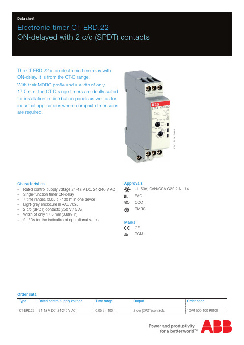
2C D C 251 091 F 0006Electronic timer CT-ERD.22ON-delayed with 2 c/o (SPDT) contactsThe CT-ERD.22 is an electronic time relay with ON-delay. It is from the CT-D range.With their MDRC profile and a width of only17.5 mm, the CT-D range timers are ideally suited for installation in distribution panels as well as for industrial applications where compact dimensions are required.Characteristics–Rated control supply voltage 24-48 V DC, 24-240 V AC –Single-function timer ON-delay–7 time ranges (0.05 s - 100 h) in one device –Light-grey enclosure in RAL 7035 – 2 c/o (SPDT) contacts (250 V / 5 A) –Width of only 17.5 mm (0.689 in)– 2 LEDs for the indication of operational statesApprovalsA UL 508, CAN/CSA C22.2 No.14REAC E CCCLRMRSMarksa CE bRCMOrder dataType Rated control supply voltage Time range OutputOrder codeCT-ERD.2224-48 V DC, 24-240 V AC0.05 s - 100 h2 c/o (SPDT) contacts1SVR 500 100 R01002 - Electronic timer CT-ERD.22 | Data sheetFunctions Operating controls2C D C 251 091 F 00061 Rotary switch for the preselection of the time range2 Potentiometer with direct reading scale for the fine adjustmentof the time delay3 Indication of operational states U: green LEDV control supply voltage applied W timing R: yellow LEDV output relays energized 4 Circuit diagramApplicationWith their structural form and their width of only 17.5 mm, the CT-D range timers are ideally suited for installation indistribution panels.Operating modeThe CT-ERD.22 has 2 c/o (SPDT) contacts and offers 7 time ranges, from 0.05 s to 100 h. The time delay range is rotary switch selectable on the front of the unit. The fine adjustment of the time delay is made via an internal potentiometer, with a direct reading scale, on the front of the unit.Function descriptions / diagramsA ON-delayThis function requires continuous control supply voltage for timing. Timing begins when control supply voltage is applied.The green LED flashes during timing. When the selected time delay is complete, the output relays energize and the flashing green LED turns steady. If control supply voltage is interrupted, the output relays de-energize and the time delay is reset.Electrical connectionData sheet| Electronic timer CT-ERD.22 - 3Data at T a = 25 °C and rated values, unless otherwise indicatedInput circuitsSupply circuit A1-A2Rated control supply voltage U s24-240 V AC, 24-48 V DCRated control supply voltage U s tolerance-15...+10 %Typical current / power consumption24 V DC21 mA / 0.5 W115 V AC20 mA / 1.2 VA230 V AC31mA / 1.9 VARated frequency DC; 50/60 HzFrequency range AC47-63 HzPower failure buffering time min. 20 msRelease voltage> 10 % of the min. rated control supply voltage U sTiming circuitKind of timer Single-function timer ON-delayTime ranges 0.05 s - 100 h0.05-1 s, 0.5-10 s, 5-100 s, 0.5-10 min, 5-100 min, 0.5-10 h, 5-100 h Recovery time< 50 msRepeat accuracy (constant parameters)D t < ± 0.5 %Accuracy within the rated control supply voltage tolerance D t < 0.005 % / VAccuracy within the temperature range D t < 0.06 % / °CSetting accuracy of time delay± 10 % of full-scale valueUser interfaceIndication of operational statesControl supply voltage / timing U: green LED V: control supply voltage appliedW: timingRelay status R: yellow LED V: output relays energizedOutput circuitKind of output15-16/18relay, 1st c/o (SPDT) contact25-26/28relay, 2nd c/o (SPDT) contactContact material Cd-freeRated operational voltage U e250 VMinimum switching voltage / Minimum switching current12 V / 100 mAMaximum switching voltage / Minimum switching current see load limit curve / see load limit curveRated operational current I e AC-12 (resistive) at 230 V 5 AAC-15 (inductive) at 230 V 3 ADC-12 (resistive) at 24 V 5 ADC-13 (inductive) at 24 V 2 AAC rating (UL 508)utilization category(Control Circuit Rating Code)B 300max. rated operational voltage300 V ACmaximum continuous thermal current at B 300 5 Amax. making/breaking apparent power at B 3003600 VA / 360 VAMechanical lifetime30 x 106 switching cyclesElectrical lifetime AC-12, 230 V, 4 A0.1 x 106 switching cyclesMaximum fuse rating to achieve short-circuit protection n/c contact 6 A fast-acting n/o contact10 A fast-acting4 - Electronic timer CT-ERD.22 | Data sheetMTBF on requestDuty time100 %Dimensions (W x H x D)product dimensions17.5 x 80 x 58 mm (0.69 x 3.15 x 2.28 in)packaging dimensions89 x 65 x 20 mm (3.50 x 2.56 x 0.79 in)Weight Nettogewicht0.068 kg (0.150 lb)Bruttogewicht0.081 kg (0.179 lb)Mounting DIN rail (IEC/EN 60715), snap-on mounting without any tool Mounting position anyMinimum distance to other units, normal operation mode horizontal not necessary vertical not necessaryDegree of protection housing IP50terminals IP20Electrical connectionConnecting capacity fine-strand with wire end ferrule 2 x 0.5-1.5 mm2 / 1 x 0.5-2.5 mm2 (2 x 20-16 AWG / 1 x 20-14 AWG) fine-strand without wire end ferrule 2 x 0.5-1.5 mm2 / 1 x 0.5-2.5 mm2 (2 x 20-16 AWG / 1 x 20-14 AWG)rigid 2 x 0.5-1.5 mm2 / 1 x 0.5-4 mm2 (2 x 20-16 AWG / 1 x 20-12 AWG) Stripping length7 mm (0.28 in)Tightening torque0.5-0.8 Nm (4.43-7.08 lb.in)Environmental dataAmbient temperature ranges operation -20...+60 °C (-4...+140 °F)storage-40...+85 °C (-40...+185 °F)Climatic class (IEC/EN 60068-2-30)3k3Relative humidity range25 % to 85 %Vibration, sinusoidal (IEC/EN 60068-2-6)20 m/s2, 10 cycles, 10...150...10 HzShock, half-sine (IEC/EN 60068-2-27)150 m/s2, 11 msIsolation dataRated insulation voltage U i input circuit / output circuit300 Voutput circuit 1 / output circuit 2300 VRated impulse withstand voltage U imp between all isolated circuits 4 kV; 1.2/50 μsPower-frequency withstand voltage between all isolated circuits(test voltage)2.5 kV, 50 Hz, 60 sBasic insulation (IEC/EN 61140)input circuit / output circuit300 VProtective separation (IEC/EN 61140, EN 50178)input circuit / output circuit250 VPollution degree3Overvoltage category IIIStandards / DirectivesStandards IEC/EN 61812-1Low Voltage Directive2014/35/EUEMC directive2014/30/EURoHS Directive2011/65/ECData sheet| Electronic timer CT-ERD.22 - 56 - Electronic timer CT-ERD.22 | Data sheetElectromagnetic compatibilityInterference immunity toIEC/EN 61000-6-2electrostatic discharge IEC/EN 61000-4-2Level 3 (6 kV / 8 kV)radiated, radio-frequency, electromagnetic fieldIEC/EN 61000-4-3Level 3 (10 V/m)electrical fast transient / burst IEC/EN 61000-4-4Level 3 (2 kV / 5 kHz)surgeIEC/EN 61000-4-5Level 3 (2 kV L-L)conducted disturbances, induced by radio-frequency fields IEC/EN 61000-4-6Level 3 (10 V)Interference emissionIEC/EN 61000-6-3high-frequency radiated IEC/CISPR 22,EN 55022Class Bhigh-frequency conductedIEC/CISPR 22,EN 55022Class BTechnical diagramsLoad limit curvesAC load (resistive) DC load (resistive)Derating factor F for inductive AC loadContact lifetimeDimensionsin mm andinchesFurther documentationDocument title Document type Document numberElectronic products and relays Technical catalogue2CDC 110 004 C02xxCT-D range Instruction manual1SVC 500 010 M1000You can find the documentation on the internet at /lowvoltage-> Automation, control and protection -> Electronic relays and controls -> Electronic timers.CAD system filesYou can find the CAD files for CAD systems at -> Low Voltage Products & Systems -> Control Products -> Electronic Relays and Controls.Data sheet| Electronic timer CT-ERD.22 - 7ABB STOTZ-KONTAKT GmbHP. O. Box 10 16 8069006 Heidelberg, Germany Phone: +49 (0) 6221 7 01-0Fax: +49 (0) 6221 7 01-13 25E-mail:*****************.comYou can find the address of your local sales organisation on theABB home page/contacts-> Low Voltage Products and Systems Contact usNote:We reserve the right to make technical changes or modify the contents of this document without prior notice. With regard to purchase orders, the agreed particulars shall prevail. ABB AG does not accept any responsibility whatsoever for potential errors or possible lack of information in this document.We reserve all rights in this document and in the subject matter and illustrations contained therein. Any reproduction, disclosure to third parties or utilization of its contents – in wholeor in parts – is forbidden without prior written consent of ABB AG.Copyright© 2016 ABBAll rights reserved D o c u m e n t n u m b e r 2 C D C 1 1 1 1 6 0 D 0 2 0 1 ( 0 8 . 2 0 1 6 )。
电子计时器 CT-APS.21 延时关机功能 SPDT 接触器说明书

Electronic timer CT-APS.21OFF-delayed with 2 c/o (SPDT) contactsThe CT-APS.21 is an electronic timer from the CT-S range with OFF-delay. It provides 10 time ranges and a continuous rated control voltage that enables worldwide use regardless of the supply voltage.All electronic timers from the CT-S range areavailable with two different terminal versions. You can choose between the proven screw connection technology (double-chamber cage connection terminals) and the completely tool-free Easy Connect Technology (push-in terminals).Characteristics–Rated control supply voltage 24-240 V AC/DC –OFF-delay timer with auxiliary voltage –10 time ranges (0.05 s - 300 h)–Control input with voltage-related triggering to start timing –Precise adjustment by front-face operating elements –Screw connection technology or Easy ConnectTechnology available–Housing material for highest fire protection classificationUL 94 V-0–Tool-free mounting and demounting on DIN-rail – 2 c/o (SPDT) contacts –Width of 22.5 mm– 2 LEDs for status indication Order data Electronic timersType Rated control supply voltage Connection technology Time ranges Order codeCT-APS.21P 24-240 V AC/DC Push-in terminals 0.05 s - 300 h 1SVR 740 180 R0300CT-APS.21S24-240 V AC/DCScrew type terminals0.05 s - 300 h1SVR 730 180 R0300AccessoriesType DescriptionOrder codeADP .01Adapter for screw mounting on panel 1SVR 430 029 R0100MAR.01Marker label1SVR 366 017 R0100COV.11Sealable transparent cover1SVR 730 005 R0100Approvals A UL 508, CAN/CSA C22.2 No.14C GL D GOST K CB scheme ECCCMarks aCE bC-Tick2C D C 251 036 V 00112 - Electronic timer CT-APS.21 | Data sheetConnection technologyMaintenance free Easy Connect Technology with push-in terminalsType designation CT-xxS.yyPApproved screw connection technology with double-chamber cage connection terminals Type designation CT-xxS.yySPush-in terminals–Tool-free connection of rigid and flexible wires withwire end ferrule according to DIN 46228-1-A 4-9, DIN 46228-4-E 4-10Wire size: 2 x 0.5-1.5 mm², (2 x 20 - 16 AWG) –Easy connection of flexible wires without wire endferrule by opening the terminals –No retightening necessary–One operation lever for opening both connectionterminals–For triggering the lever and disconnecting of wiresyou can use the same tool (Screwdriver according to DIN ISO 2380-1 Form A 0.8 x 4 mm (0.0315 x 0.157 in), DIN ISO 8764-1 PZ1 ø 4.5 mm (0.177 in))–Constant spring force on terminal point independentof the applied wire type, wire size or ambientconditions (e. g. vibrations or temperature changes) –Opening for testing the electrical contacting –Gas-tightDouble-chamber cage connection terminals–Terminal spaces for different wire sizes:fine-strand with/without wire end ferrule: 1 x 0.5-2.5 mm² (2 x 20 - 14 AWG), 2 x 0.5-1.5 mm² (2 x 20 - 16 AWG) rigid:1 x 0.5-4 mm² (1 x 20 - 12 AWG), 2 x 0.5-2.5 mm² (2 x 20 - 14 AWG)–One screw for opening and closing of both cages –Pozidrive screws for pan- or crosshead screwdriversaccording to DIN ISO 2380-1 Form A 0.8 x 4 mm (0.0315 x 0.157 in), DIN ISO 8764-1 PZ1 ø 4.5 mm (0.177 in)Both the Easy Connect Technology with push-in terminals and screw connection technology with double-chamber cageconnection terminals have the same connection geometry as well as terminal position.2C D C 253 025 F 00112C D C 253 026 F 0011Data sheet | Electronic timer CT-APS.21 - 3Functions Operating controlRotary switch for the preselection of the time range Fine adjustment of the time delay Indication of operational statesU: green LED - control supply voltage / timing R: yellow LED - status of output relays4 Marker labelApplicationThe CT-S range timers are designed for use in industrial applications. They operate over an universal range of supplyvoltages and a large time delay range, within compact dimensions. The easy-to-set front-face potentiometers, with direct reading scales, provide accurate time delay adjustment.Operating modeThe CT-APS.21 with 2 c/o (SPDT) contacts offers 10 time ranges, from 0.05 s to 300 h, for the adjustment of the time delay. The time delay range is rotary switch selectable. The fine adjustment of the time delay is made via an internal potentiometer, with a direct reading scale, on the front of the unit.Timing is displayed by a flashing green LED labelled U/T.2C D C 251 036 V 0011Function diagramOFF-delay with auxiliary voltageThis function requires continuous control supply voltage for timing.If control input A1-Y1/B1 is closed, the output relay energizes immediately. If control input A1-Y1/B1 is opened, the time delay starts. The green LED flashes during timing. When the selected time delay is complete, the output relay de-energizes and the flashing green LED turns steady.If control input A1-Y1/B1 recloses before the time delay is complete, the time delay is reset and the output relay does not change state. Timing starts again when control input A1-Y1/B1 re-opens.If control supply voltage is interrupted, the output relay de-energizes and the time delay is reset.Electrical connectionWiring instructionsControl input (voltage-related triggering)The control input Y1/B1 is triggered with electric potential against A2. It is possible to use the control supply voltage from terminal A1 or any other voltage within the rated control supply voltage range.4 - Electronic timer CT-APS.21 | Data sheetTechnical dataData at T a = 25 °C and rated values, unless otherwise indicatedInput circuitsSupply circuit A1‑A2Rated control supply voltage U S24-240 V AC/DCRated control supply voltage U S tolerance-15...+10 %Rated frequency DC n/aAC50/60 HzFrequency range AC47-63 HzTypical current / power consumption24 V DC24 mA / on request115 V AC22 mA / on request230 V AC12 mA / on requestPower failure buffering time24 V DC 1.2 mA230 V AC8 mAControl circuitControl input, control function A1-Y1/B1start timing externalKind of triggering voltage-related triggeringRestistance to reverse polarity yesPolarized noCapable for switching a parallel load yesMaximum cable length to the control inputs50 m - 100 pF/mMinimum control pulse length20 msControl voltage potential see rated control supply voltage U SCurrent consumption of the control input24 V DC 1.2 mA230 V AC8 mATiming circuitKind of timer Single-function timer OFF-delay with auxiliary voltageTime ranges 0.05 s - 300 h0.05-1 s, 0.15-3 s, 0.5-10 s, 1.5-30 s, 5-100 s,15-300 s, 1.5-30 min, 15-300 min, 1.5-30 h, 15-300 h Recovery time< 50 msRepeat accuracy (constant parameters)Δt <± 0.2 %Accuracy within the rated control supply voltage toleranceΔt < 0.004 %/VAccuracy within the temperature rangeΔt < 0.03 %/°CUser interfaceIndication of operational statesControl supply voltage / timing U/T: green LED V: control supply voltage appliedU/T: green LED W: timingRelay status R: yellow LED V: output relay energizedData sheet| Electronic timer CT-APS.21 - 5Output circuitsKind of output15-16/18Relay, 1. c/o (SPDT) contact25-26/28Relay, 2. c/o (SPDT) contact Contact material Cd-freeRated operational voltage U e250 VMinimum switching voltage / Minimum switching current12 V / 10 mAMaximum switching voltage / Minimum switching current see ‘Load limit curves’ on page 8 Rated operational current I e (IEC/EN 60947-5-1)AC12 (resistive) at 230 V 4 AAC15 (inductive) at 230 V 3 ADC12 (resistive) at 24 V 4 ADC13 (inductive) at 24 V 2 AAC rating (UL 508)utilization category (ControlCircuit Rating Code)B 300max. rated operational voltage300 V ACmax. continuous thermalcurrent at B 3005 Amax. making / breakingapparent power at B 3003600/360 VAMechanical lifetime30 x 106 switching cycles Electrical lifetime AC12, 230 V, 4 A0.1 x 106 switching cyclesMaximum fuse rating to achieve short-circuit protection (IEC/EN 60947-5-1)n/c contact 6 A fast-acting n/o contact10 A fast-actingGeneral dataElectrical connection6 - Electronic timer CT-APS.21 | Data sheetEnvironmental dataAmbient temperature ranges operation-40...+60 °Cstorage-40...+85 °CDamp heat, cyclic (IEC/EN 60068-2-30) 6 x 24 h cycle, 55 °C, 95 % RH Vibration, sinusoidal (IEC/EN 60068-2-6)functioning40 m/s2, 10-58/60-150 Hzresistance60 m/s2, 10-58/60-150 Hz, 20 cycles Vibration, seismic (IEC/EN 60068-3-3)functioning20 m/s²Shock, half-sine (IEC/EN 60068-2-27)functioning100 m/s2, 11 ms, 3 shocks/directionresistance300 m/s2, 11 ms, 3 shocks/direction Isolation dataRated insulation voltage U i output circuit 1 /output circuit 2300 Vinput circuit / output circuit500 VRated impulse withstand voltage U imp between allisolated circuits (IEC/EN 60664-1, VDE 0110)4 kV; 1.2/50 µsPower-frequency withstand voltage test between all isolated circuits (test voltage)routine test: 2.0 kV; 50 Hz, 1 s type test: 2.5 kV; 50 Hz, 1 minBasic insulation (IEC/EN 61140)input circuit / output circuit500 VProtective separation (IEC/EN 61140; IEC/EN 50178;VDE 0106 part 101 and part 101/A1)input circuit / output circuit250 VPollution degree(IEC/EN 60664-1, VDE 0110)3Overvoltage category(IEC/EN 60664-1, VDE 0110)IIIStandardsProduct standard IEC 61812-1, EN 61812-1 + A11,DIN VDE 0435 part 2021Low Voltage Directive2006/95/ECEMC Directive2004/108/ECRoHS Directive2002/95/ECElectromagnetic compatibilityInterference immunity to IEC/EN 61000-6-1, IEC/EN 61000-6-2electrostatic discharge IEC/EN 61000-4-2Level 3, 6 kV / 8 kVradiated, radio-frequency, electromagnetic field IEC/EN 61000-4-3Level 3, 10 V/m (1 GHz) / 3 V/m (2 GHz) /1 V/m (2.7 GHz)electrical fast transient / burst IEC/EN 61000-4-4Level 3, 2 kV / 5 kHzsurge IEC/EN 61000-4-5Level 4, 2 kV A1-A2conducted disturbances, induced by radio-frequency fieldsIEC/EN 61000-4-6Level 3, 10 Vharmonics and interharmonics IEC/EN 61000-4-13Level 3Interference emission IEC/EN 61000-6-3, IEC/EN 61000-6-4high-frequency radiated IEC/CISPR 22, EN 55022Class Bhigh-frequency conducted IEC/CISPR 22, EN 55022Class BData sheet| Electronic timer CT-APS.21 - 7Technical diagramsLoad limit curves8 - Electronic timer CT-APS.21 | Data sheetDimensionsin mm and inchesAccessoriesin mm and inchesFurther documentationDocument title Document type Document numberElectronic Products and Relays Technical catalogue2CDC 110 004 C020xCT-APS, CT-ERS, CT-MVS, CT-SDS Instruction manual1SVC 730 020 M0000You can find the documentation on the internet at /lowvoltage -> Control Products ->Electronic Relays and Controls -> Time RelaysData sheet| Electronic timer CT-APS.21 - 9ABB STOTZ‑KONTAKT GmbHP. O. Box 10 16 8069006 Heidelberg, Germany Phone: +49 (0) 6221 7 01-0Fax: +49 (0) 6221 7 01-13 25E-mail:*****************.comYou can find the address of your local sales organization on theABB home page/contacts-> Low Voltage Products and Systems Contact usNote:We reserve the right to make technical changes or modify the contents of this document without prior notice. With regard to purchase orders, the agreed particulars shall prevail. ABB AG does not accept any responsibility whatsoever for potential errors or possible lack of information in this document.We reserve all rights in this document and in the subject matter and illustrations contained therein. Any reproduction, disclosure to third parties or utilization of its contents – in wholeor in parts – is forbidden without prior written consent of ABB AG.Copyright© 2011 ABBAll rights reserved D o c u m e n t n u m b e r 2 C D C 1 1 1 1 1 6 D 0 2 0 1 p r i n t e d i n G e r m a n y ( 0 4 / 2 0 1 1 )。
公牛智立方wifi说明书

公牛智立方wifi说明书1、公牛WiFi智能插座就具有自定义模式功能,目前手机APP里面可以预设鱼缸和热水器场景模式,这也是这款产品最经常的使用情境。
比如平时控制电热水器也是一件麻烦活,开机需要时间预加热,到家再打开显然已经来不及。
用公牛WiFi智能插座远程遥控启动,到家就能洗热水澡,舒心放心又方便!夏天回家开空调,还得再忍耐一段时间等温度下降怎么行?用公牛WiFi智能插座2代设置远程通电,让你清凉到家!2、自定义模式此外还提供了定时任务、延时任务、循环任务等多种控制,用户可以根据自己的需求来为家里的电器设置不同的模式,自动周期性通断电源、控制家电设备的运行,从而起到节能环保、延长家电使用寿命的作用。
3、除此之外,公牛WiFi智能插座还拥有充电保护模式,专门针对手机、平板等需要充电的数码设备,可以自行设定插座的关闭时间,以免造成手机过充现象的发生,延长电池的使用寿命。
4.宽带断网怎么整,插座还能自己管理设置?没关系,公牛WiFi 智能插座2代自带定时记忆功能,断网也可正常原定任务,让你用的放心,出门更安心!5、公牛WiFi智能插座2代上还加入了"记忆功能",只要开启它,即使插座在断电之后恢复通电,也能保证相联的电器设备按原状态继续运行而不是“意外罢工”,免去了用户使用过程中的后顾之忧。
公牛wifi插座APP连接这个操作不难,说明书上也有详细介绍并附上步骤演示。
首先,扫描二维码,包装盒上的或者说明书上的都可以,然后进入APP下载界面,点击下载,下载安装完后,注册账号并登陆,如果还没有账号而又懒得注册,可以用微信或者京东的账号登陆。
然后就添加设备,有扫一扫添加和蓝牙添加,但是方便起见,建议使用扫一扫,二维码也是在说明书上,然后就要输入WiFi密码,输入WiFi密码是为了让插座也连接上WiFi,接着点击下一步进入搜索设备界面,等搜索出设备后,点击添加设备就完成了,最后,假如你买的插座不只一个,为方便识别,最好给设备进行重命名,例如客厅插座,卧室插座等。
温控定时器 CX-T02C中文说明书
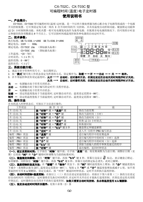
CX-T02C、CX-T03C型可编程时间(温度)电子定时器使用说明书一、产品简介:CX-T02C、CX-T03C型可编程时间(温度)定时器,是一个以单片微处理器为核心配合电子电路等组成的一个电源开关控制装置。
它可预设定每天或一周内8次不同时间的开/关控制,并具有温度自动控制功能、键盘锁定功能和12/24小时制转换功能。
本机内置一枚可充电镍氢电池作为备用电源,在脱离市电电源的情况下,仍可保持计时显示和储存的各项数据达9个月以上。
它可以按时间或温度控制各种电器的自动定时开关。
二、技术参数:执行标准:GB/T14536.1-1998 GB/T14536.8-1996额定电压:220V ~ 50Hz额定电流:CX-T02C 10A (国标插头标准)CX-T03C 16A (国标插头标准)工作温度:-20~70℃计时误差:≤±1秒/天温控范围:0~99℃温控误差:≤±1℃三、系统功能介绍:1.液晶全屏字符和外形尺寸,如右图所示:2. 按“模式”键可将工作状态设定为所需的方式,设定顺序为:取暖开自动关制冷。
3.在不带温控和没有设定温度时:从开自动时,定时器即开启,在到达设定的自动关闭时间程序时才关闭。
从关自动时,定时器即关闭,在到达设定的自动开启时间程序时才开启。
关电源输出处于经常关闭状态。
自动电源输出处于执行编写的定时开/关程序状态。
开电源输出处于经常开启状态。
取暖设定的温度值高于当前温度时,定时器自动开启,温度设定范围0~99℃。
制冷设定的温度值低于当前温度时,定时器自动开启,温度设定范围0~99℃。
四、操作方法在本机进入时钟状态后,可按以下方法进行操作:工作状态操作方法功能开/自动/关按“时钟”键 +“星期”键修改当前星期开/自动/关按“时钟”键 +“时”键修改当前时间(小时)开/自动/关按“时钟”键 +“分”键修改当前时间(分)开/自动/关按“时钟”键 +“设定”键转换12/24小时制式开/自动/关按“时钟”键 +“模式”键转换夏时制开/自动/关按“时钟”键 +“S/A”键3秒键盘锁定和键盘解锁开/自动/关按“定时”键进入开/关程序(PRG)编写状态编程(PRG)状态按“星期”键进行编写程序中的星期选择编程(PRG)状态按“时”键进行编写程序中的时间(小时)选择编程(PRG)状态按“分”键进行编写程序中的时间(分)选择编程(PRG)状态按“S/A”键清除当前输入的程序和恢复最近的程序编程(PRG)状态按“时钟”键退出编程,返回时钟状态(一)、校正星期和时间:左手按住“时钟”键不放,右手按“星期”键,将星期调整为当前日期,调整好日期(星期)后再按“时”和“分”键将时钟调整为当前的标准时间。
定时器使用说明
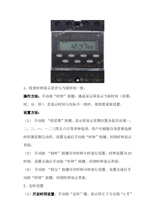
1、检查时钟显示是否与当前时间一致。
操作方法:手动按“时钟”按键,液晶显示屏显示当前时间(星期、时、分、秒)。
若显示时间与实际不一致时,则需要重新设置。
设置方法:(1)手动按“校星期”按键,显示屏显示星期位置会依次出现一、二、三、…、一二三四五六日等多种选项,用户可根据自身需要选择时控器星期几动作。
设置完成后手动按“时钟”按键,回到时钟显示界面。
(2)手动按“校时”按键可对时钟小时进行设置,时钟设置为24时制。
设置完成后手动按“时钟”按键,回到时钟显示界面。
(3)手动按“校分”按键可对时钟分钟进行设置。
设置完成后手动按“时钟”按键,回到时钟显示界面。
2、定时设置(1)开启时间设置:手动按“定时”键,显示屏左下方出现“1开”字样(表示第一次开启时间)。
再分别按“校时”、“校分”键,输入所需照明开启的时间。
(2)关闭时间设置:手动按“定时”键,显示屏左下方出现“1关”字样(表示第一关闭时间) 。
再分别按“校时”、“校分”键,输入所需照明关闭的时间。
(3)定时开、关的时间设置完成后,在时钟显示状态下按“定时设置自动/手动”键,将显示下方的“”符号调到“自动”位置。
此时,时控开关才能根据所设定的时间自动开、关电路。
如在使用过程中需要临时开、关电路,则只需按“自动/手动”键将“”符号调到相应的“开”或“关”的位置,立即可实现照明的开启和关闭操作。
(4)连续按下“定时”键,显示屏左下方将依次显示“2开、2关、3开、3关、……、16开、16关”(型号不同控制点数也不一样,但操作方法相同),具体可参考上述两步骤进行设置(注:实际只用一对控制点数,即1开、1关。
如不需所有的控制点数,则需要将其它不用控制点数的显示界面按“取消/恢复”键,将多余各组的时间消除,使其在显示屏上显示为“- -:- -”状态;不是显示为00:00)。
设置完成后手动按“时钟”按键,回到时钟显示界面。
定时器说明书

定时器说明书定时器说明书---1. 简介定时器是一种可以按照设定的时间间隔执行任务的设备或软件。
它可以用于各种场景,如自动关灯、定时提醒、定时操作等。
通过设定定时器,我们可以在特定的时间间隔内,自动触发某些操作,提高生活和工作的效率。
2. 功能特点- **简单易用**: 定时器提供简单易用的操作界面,用户可以轻松设定所需的时间间隔和任务。
- **多功能**: 定时器具备多种功能,如定时关灯、定时提醒、定时播放音乐等,满足用户的多样化需求。
- **可控性**: 用户可以随时修改、取消定时器设置,具备较高的可控性。
- **多平台支持**: 定时器支持在各种平台上使用,如手机、电脑等。
- **稳定可靠**: 定时器采用高质量的算法和稳定的运行环境,确保定时任务按时触发。
3. 使用方法3.1 设定定时器在使用定时器之前,用户需要按照以下步骤设定定时器:1. 打开定时器软件或设备。
2. 进入定时器设置界面。
3. 输入所需的时间间隔。
可以选择常用的时间间隔,也可以手动输入自定义的时间间隔。
4. 选择所需的任务类型。
可以是定时关灯、定时提醒、定时播放音乐等。
5. 确认设置并保存。
3.2 启动定时器在设定好定时器后,用户可以按照以下步骤启动定时器:1. 打开定时器软件或设备。
2. 进入定时器界面。
3. 确认当前的定时器设置。
4. 点击启动按钮,开始倒计时。
3.3 修改定时器设置如果用户需要修改已设定的定时器,可以按照以下步骤进行:1. 打开定时器软件或设备。
2. 进入定时器设置界面。
3. 找到需要修改的定时器设置。
4. 修改所需的时间间隔或任务类型。
5. 确认修改并保存。
3.4 取消定时器如果用户需要取消已设定的定时器,可以按照以下步骤进行:1. 打开定时器软件或设备。
2. 进入定时器界面。
3. 找到需要取消的定时器设置。
4. 点击取消按钮。
4. 注意事项在使用定时器时,需要注意以下事项:- **合理设置时间间隔**: 根据实际需求,合理设定时间间隔,避免过长或过短的时间间隔造成不必要的困扰。
公牛牌电子式定时器说明书
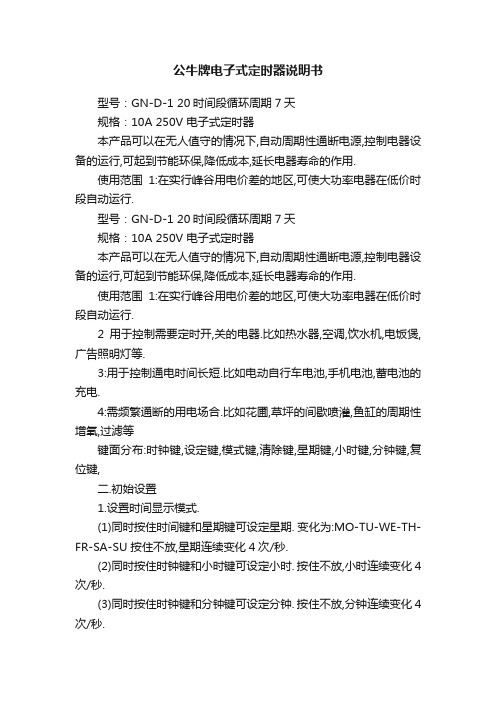
公牛牌电子式定时器说明书型号:GN-D-1 20时间段循环周期7天规格:10A 250V 电子式定时器本产品可以在无人值守的情况下,自动周期性通断电源,控制电器设备的运行,可起到节能环保,降低成本,延长电器寿命的作用.使用范围1:在实行峰谷用电价差的地区,可使大功率电器在低价时段自动运行.型号:GN-D-1 20时间段循环周期7天规格:10A 250V 电子式定时器本产品可以在无人值守的情况下,自动周期性通断电源,控制电器设备的运行,可起到节能环保,降低成本,延长电器寿命的作用.使用范围1:在实行峰谷用电价差的地区,可使大功率电器在低价时段自动运行.2用于控制需要定时开,关的电器.比如热水器,空调,饮水机,电饭煲,广告照明灯等.3:用于控制通电时间长短.比如电动自行车电池,手机电池,蓄电池的充电.4:需频繁通断的用电场合.比如花圃,草坪的间歇喷灌,鱼缸的周期性增氧,过滤等键面分布:时钟键,设定键,模式键,清除键,星期键,小时键,分钟键,复位键,二.初始设置1.设置时间显示模式.(1)同时按住时间键和星期键可设定星期. 变化为:MO-TU-WE-TH-FR-SA-SU 按住不放,星期连续变化4次/秒.(2)同时按住时钟键和小时键可设定小时. 按住不放,小时连续变化4次/秒.(3)同时按住时钟键和分钟键可设定分钟. 按住不放,分钟连续变化4次/秒.(4)按住时钟键3秒,时钟显示增加1小时(夏令时显示),此时,显示屏上有"+1H"显示,再按住3秒恢复正常时间显示,"+1H"标志消失(夏令时取消)2.当前时间校准.(1)按住时间键不动;(2)同时再按小时键即可调整时间小时显示,点按每次增加一小时,长按可进行快速调整;(3)采用同样的方式可调整分钟和星期的显示3控制模式切换在时钟状态下连续按模式键,液晶显示屏的左边将循环显示AUTO OFF(自动关),ON(手动开),AUTO ON(自动开),OFF(手动关).三.定时开、关的设置1.按设定键,进入第1个时间段的通电时间设定闹钟:若二十秒内没有进行任何操作,定时器会自动恢复到时间校准状态。
定时控制开关说明书
说明书功能和用途本产品能根据用户设定的时间、自动打开和关闭各种用电设备的电源。
控制对象可以是路灯、霓虹灯、广告招牌灯、生产设置、广播电视设备等一切需要定时打开和关闭的电路器设备和家用电器。
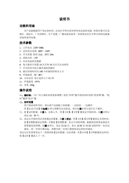
技术参数1、工作电压220V/50Hz2、适用电压范围160V~240V3、开关容量阻性25A、感性20A4、消耗功率<1W5、内有电池保存数据6、每天最多可设置10次开和10次关手自动两用7、开关时间可按天循环或按周循环8、最长控制时间为168小时最短控制为1分9、环境温度-20~60℃10、计时误差每天走时小于0.5秒11、环境湿度<95%12、净重430g操作说明一、调时钟:(出厂时已调好如需重新调整)按住“时钟”键不放的同时再按“校星期”键,“校时”键和“校分”键。
二、定时设置用户阅读说明书时,请认清产品面板上的按键,一边阅读,一边操作。
用【自动/手动】键如图1所示调整至自动状态,然后如图5所示进行以下操作:①、按【定时】键,如图1,出现1开,用【小时】、【分钟】键设定开始时间,如图3所示设定18:30开,②、设定完开始时间后再按【定时】键,如图2所示,用【小时】、【分钟】键设定关闭时间,按【星期】键设定周期,不断按【星期】键,显示不同的周期,根据您的需要选择适合需要通电的周期,如图4所示,设定23:20关,表示18:30至23:20这段时间一直自动通电。
周一至周日都亮起,周期为周一至周日都按您设定的时间通电。
设定完后若需要设定下一组则再按【定时】键,以此类推,用【小时】、【分钟】键设定时间,按【定时】键进入下一步。
若要退出则按【时钟】键,数据自动保存,系统将按您设定时间按时通电。
如果设定完没按【时钟】键退出,30秒后自动退出,进入平常时钟显示状态。
数据也自动保存。
图5三、关闭定时设置如果需要关闭某一组,则按【定时】键,进入到某组时,按【取消/恢复】键,如图1所示,显示--:--表示这组关闭。
定时器 时间开关 说明书
⬉ᄤ⏽఼
ķ⬉⑤䚼
ᇚ㒭ќⱘ⬉य़ ݙ䚼ᦤկ
䕧 ߎ 䚼
ĺ䕧ߎ䚼 䕧ߎ䆒 䕧ߎֵো
᭄ᄫ䴶ᵓ㸼
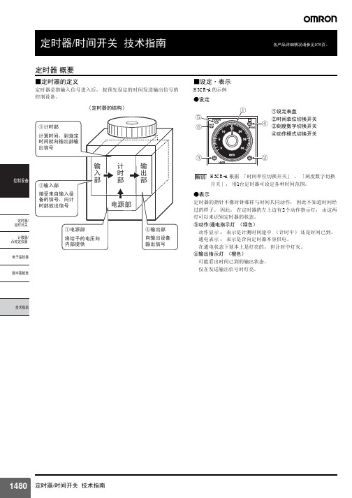
■设定·表示
H3CR-A的示例
●设定
ķ Ļ ļ
①设定表盘 ②时间单位切换开关
ĺ ③刻度数字切换开关
④动作模式切换开关
Ĺ
ĸ
㾷䇈 H3CR-A 根据 「时间单位切换开关」 、 「刻度数字切换 开关」, 用1台定时器可设定各种时间范围。
b接点叫做c接点。
同步电动机
SM
、 含义相同。b接
点在右侧或上侧。
手一旦离开便可以复 位的接点,用于按钮 开关操作接点等接 点。(按压型、拉拔 型、旋钮型共通)
为a接点 为b接点
和电源频率同步旋转
MS
的小型电机
限时动作接点
为a接点 为b接点 继电器
X
X
表示磁力继电器
限时复位接点
为a接点 为b接点 发光二极管
●复位时间 限时操作过程中或限时动作完成后, 从操作电路的电压切断开始 到定时器返回到起动前状态为止的时间。
᪡⬉䏃 ˄ ⬉⑤˅
᪡ᯊ䯈
ӥℶᯊ䯈
䰤ᯊ⚍ab⚍⚍
ݙ䚼ᴎᵘ ݙ䚼⬉䏃
ࡼᯊ䯈 ֱᣕᯊ䯈 ԡᯊ䯈
定时器的复位包含接点的复位、 指针等机构部位的复位、 电容器 等电路部位的复位, 定时器的复位时间是指这些复位全部完成时 的值。 在规定复位时间以下的休止时间内使用定时器时, 动作时间会缩 短, 瞬间动作时有时无, 不能发挥正常的定时器动作。 因此, 定 时器的休止时间必须在规定复位时间以上。
᭄ᄫ䴶ᵓ㸼
●耐久冲击 指运送过程中或使用过程中没有由于冲击造成各部位损伤, 能满 足动作特性的范围的冲击。
TU-A72 电子定时器说明书
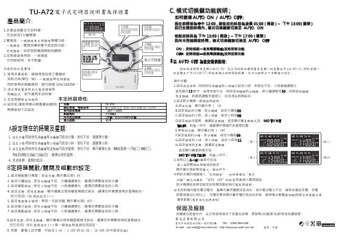
TU-A72電子式定時器說明書及保證書產品簡介:1.本產品為數位式定時器, 可定時至1分鐘間隔。
2.雙插座:一般插座及定時插座兩種功能, 一般插座:電源持續供電不具定時功能。
定時插座:定時控制電源開啟和關閉。
3.定時插座使用時,一般插座 可同時使用,互不影響。
※使用前注意事項:1. 使用本產品前,請檢視須定時之電器的 消耗功率(單位 : W),一般插座與定時插座同時使用的負載總和,請勿超過 15A/1650W。
2. 須定時的電器用品之電源開關如 為觸控式,則不適用本定時器。
3. 本定時器限室內使用。
4. 設定前,請使用筆尖輕壓重設鍵(R) 再開始如下的設定 。
A 設定現在的時間及星期:1. 設定分鐘:同時按住時鐘鍵和分鐘鍵可設定分鐘。
按住不放,請選擇分鐘。
2. 設定小時:同時按住時鐘鍵和小時鍵可設定小時。
按住不放,請選擇小時。
3. 設定星期:同時按住時鐘鍵和星期鍵可設定星期。
按住不放,顯示幕變化為:MO (星期一) TU (二) WE (三) TH (四)FR (五)SA (六)SU (日),選擇出現的星期。
4. 完成時間、星期的設定。
輸入電壓110V /60Hz 最大負載15A /1650WB 定時器開啟/關閉及組數的設定:1. 設定幾點幾分開啟:按設定鍵, 顯示幕出現1 ON 。
2. 設定分鐘開啟 : 按住分鐘鍵不放,分鐘連續變化,選擇您需要設定的分鐘。
3. 設定幾點開啟 : 按住小時鍵不放,小時連續變化,選擇您需要設定的小時。
4. 設定星期 : 按住星期鍵,顯示幕會出現各種星期模式組合,選擇您所需要使用的星期組合。
您已完成1 ON ( 開啟設定 ) >>5. 設定幾點幾分關閉:再按一次設定鍵, 顯示幕出現1 OFF 。
6. 設定幾分關閉 : 按住分鐘鍵不放,分鐘連續變化,選擇您需要設定的分鐘。
7. 設定幾點關閉 : 按住小時鍵不放,小時連續變化,選擇您需要設定的小時。
假如現在時間為星期三的12:50,您公司的飲水機想要在星期一到星期五早上8:00~11:00和星期一到星期五下午13:00~17:00的兩個上班時間段啟動。
电子计时器 CT-APS.12 延时开关说明书
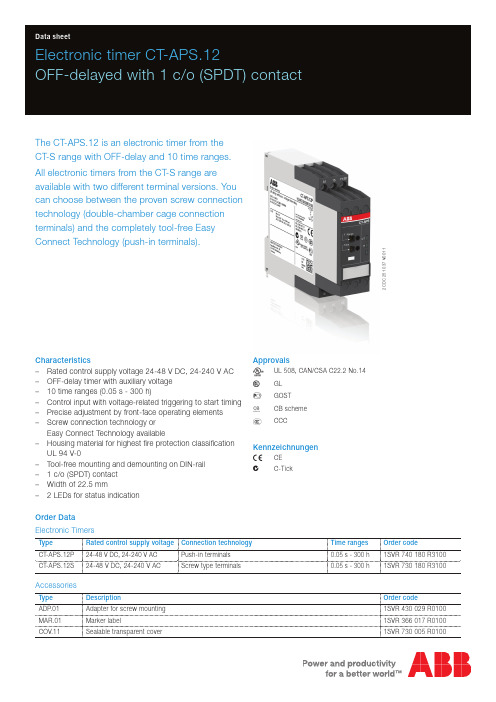
Electronic timer CT-APS.12OFF-delayed with 1 c/o (SPDT) contactThe CT-APS.12 is an electronic timer from the CT-S range with OFF-delay and 10 time ranges.All electronic timers from the CT-S range areavailable with two different terminal versions. You can choose between the proven screw connection technology (double-chamber cage connection terminals) and the completely tool-free Easy Connect Technology (push-in terminals).Characteristics–Rated control supply voltage 24-48 V DC, 24-240 V AC –OFF-delay timer with auxiliary voltage –10 time ranges (0.05 s - 300 h)–Control input with voltage-related triggering to start timing –Precise adjustment by front-face operating elements –Screw connection technology orEasy Connect Technology available–Housing material for highest fire protection classificationUL 94 V-0–Tool-free mounting and demounting on DIN-rail – 1 c/o (SPDT) contact –Width of 22.5 mm– 2 LEDs for status indication Order Data Electronic TimersType Rated control supply voltage Connection technology Time ranges Order codeCT-APS.12P 24-48 V DC, 24-240 V AC Push-in terminals 0.05 s - 300 h 1SVR 740 180 R3100CT-APS.12S24-48 V DC, 24-240 V ACScrew type terminals0.05 s - 300 h1SVR 730 180 R3100AccessoriesType DescriptionOrder codeADP .01Adapter for screw mounting 1SVR 430 029 R0100MAR.01Marker label1SVR 366 017 R0100COV.11Sealable transparent cover1SVR 730 005 R0100Approvals A UL 508, CAN/CSA C22.2 No.14C GL D GOST K CB scheme ECCCKennzeichnungen aCE bC-Tick2C D C 251 037 V 00112 - Electronic timer CT-APS.12 | Data sheetConnection technologyMaintenance free Easy Connect Technology with push-in terminalsType designation CT-xxS.yyPApproved screw connection technology with double-chamber cage connection terminals Type designation CT-xxS.yySPush-in terminals–Tool-free connection of rigid and flexible wires withwire end ferrule according to DIN 46228-1-A 4-9, DIN 46228-4-E 4-10Wire size: 2 x 0.5-1.5 mm², (2 x 20 - 16 AWG) –Easy connection of flexible wires without wire endferrule by opening the terminals –No retightening necessary–One operation lever for opening both connectionterminals–For triggering the lever and disconnecting of wiresyou can use the same tool (Screwdriver according to DIN ISO 2380-1 Form A 0.8 x 4 mm (0.0315 x 0.157 in), DIN ISO 8764-1 PZ1 ø 4.5 mm (0.177 in))–Constant spring force on terminal point independentof the applied wire type, wire size or ambientconditions (e. g. vibrations or temperature changes) –Opening for testing the electrical contacting –Gas-tightDouble-chamber cage connection terminals–Terminal spaces for different wire sizes:fine-strand with/without wire end ferrule: 1 x 0.5-2.5 mm² (2 x 20 - 14 AWG), 2 x 0.5-1.5 mm² (2 x 20 - 16 AWG) rigid:1 x 0.5-4 mm² (1 x 20 - 12 AWG), 2 x 0.5-2.5 mm² (2 x 20 - 14 AWG)–One screw for opening and closing of both cages –Pozidrive screws for pan- or crosshead screwdriversaccording to DIN ISO 2380-1 Form A 0.8 x 4 mm (0.0315 x 0.157 in), DIN ISO 8764-1 PZ1 ø 4.5 mm (0.177 in)Both the Easy Connect Technology with push-in terminals and screw connection technology with double-chamber cageconnection terminals have the same connection geometry as well as terminal position.2C D C 253 025 F 00112C D C 253 026 F 0011Data sheet | Electronic timer CT-APS.12 - 3Functions Operating controlsRotary switch for the preselection of the time range Fine adjustment of the time delay3 Indication of operational statesU: green LED - control supply voltage / timing R: yellow LED - status of output relay4 Marker labelApplicationThe CT-S range timers are designed for use in industrial applications. They operate over an universal range of supplyvoltages and a large time delay range, within compact dimensions. The easy-to-set front-face potentiometers, with direct reading scales, provide accurate time delay adjustment.Operating modeThe CT-APS.12 with 1 c/o contact offers 10 time ranges, from 0.05 s to 300 h, for the adjustment of the time delay. The time delay range is rotary switch selectable. The fine adjustment of the time delay is made via an internal potentiometer, with a direct reading scale, on the front of the unit.Timing is displayed by a flashing green LED labelled U/T.2C D C 251 037 V 0011Function diagramOFF-delay with auxiliary voltageThis function requires continuous control supply voltage for timing.If control input A1-Y1/B1 is closed, the output relay energizes immediately. If control input A1-Y1/B1 is opened, the time delay starts. The green LED flashes during timing. When the selected time delay is complete, the output relay de-energizes and the flashing green LED turns steady.If control input A1-Y1/B1 recloses before the time delay is complete, the time delay is reset and the output relay does not change state. Timing starts again when control input A1-Y1/B1 re-opens.If control supply voltage is interrupted, the output relay de-energizes and the time delay is reset.Electrical connectionWiring instructionsControl input (voltage-related triggering)The control input Y1/B1 is triggered with electric potential against A2. It is possible to use the control supply voltage from terminal A1 or any other voltage within the rated control supply voltage range.4 - Electronic timer CT-APS.12 | Data sheetTechnical DataData at T a = 25 °C and rated values, unless otherwise indicatedInput circuitsSupply circuit A1‑A2Rated control supply voltage U S24-48 V DC, 24-240 V ACRated control supply voltage U S tolerance24-48 V DC-15...+10 %24-240 V AC-15...+10 %Rated frequency DC n/aAC50/60 HzFrequency range AC47-63 HzTypical current / power consumption24 V DC230 V AC115 V AC24-48 V DC12 mA /on request- / -- / -24-240 V AC- / -50 mA /on request33 mA / on requestPower failure buffering time24 V DC min. 15 ms230 V AC min. 20 msControl circuitControl input, control function A1-Y1/B1start timing externalKind of triggering voltage-related triggeringRestistance to reverse polarity yesPolarized noCapable for switching a parallel load yesMaximum cable length to the control inputs50 m - 100 pF/mMinimum control pulse length20 msControl voltage potential see rated control supply voltage U SCurrent consumption of the control input24 V DC 1.2 mA230 V AC8 mATiming circuitKind of timer Single-function timer OFF-delay with auxiliary voltageTime ranges 0.05 s - 300 h0.05-1 s, 0.15-3 s, 0.5-10 s, 1.5-30 s, 5-100 s,15-300 s, 1.5-30 min, 15-300 min, 1.5-30 h, 15-300 h Recovery time< 80 msRepeat accuracy (constant parameters)Δt <± 0.2 %Accuracy within the rated control supply voltage toleranceΔt < 0.004 %/VAccuracy within the temperature rangeΔt < 0.03 %/°CUser interfaceIndication of operational statesControl supply voltage / timing U/T: green LED V: control supply voltage appliedU/T: green LED W: timingRelay status R: yellow LED V: output relay energizedData sheet| Electronic timer CT-APS.12 - 5Output circuitsKind of output15-16/18Relay, 1 c/o (SPDT) contact Contact material Cd-freeRated operational voltage U e250 VMinimum switching voltage / Minimum switching current12 V / 10 mAMaximum switching voltage / Minimum switching current see ‘Load limit curves’ on page 8 Rated operational current I e (IEC/EN 60947-5-1)AC12 (resistive) at 230 V 4 AAC15 (inductive) at 230 V 3 ADC12 (resistive) at 24 V 4 ADC13 (inductive) at 24 V 2 AAC rating (UL 508)utilization category (ControlCircuit Rating Code)B 300max. rated operational voltage300 V ACmax. continuous thermalcurrent at B 3005 Amax. making / breakingapparent power at B 3003600/360 VAMechanical lifetime30 x 106 switching cycles Electrical lifetime AC12, 230 V, 4 A0.1 x 106 switching cyclesMaximum fuse rating to achieve short-circuit protection (IEC/EN 60947-5-1)n/c contact 6 A fast-acting n/o contact10 A fast-actingGeneral dataElectrical connection6 - Electronic timer CT-APS.12 | Data sheetEnvironmental dataAmbient temperature ranges operation-25...+60 °Cstorage-40...+85 °CDamp heat, cyclic (IEC/EN 60068-2-30) 6 x 24 h cycle, 55 °C, 95 % RH Vibration, sinusoidal (IEC/EN 60068-2-6)functioning40 m/s2, 10-58/60-150 Hzresistance60 m/s2, 10-58/60-150 Hz, 20 cycles Vibration, seismic (IEC/EN 60068-3-3)functioning20 m/s²Shock, half-sine (IEC/EN 60068-2-27)functioning100 m/s2, 11 ms, 3 shocks/directionresistance300 m/s2, 11 ms, 3 shocks/direction Isolation dataRated insulation voltage U i input circuit / output circuit500 VRated impulse withstand voltage U imp between allisolated circuits (IEC/EN 60664-1, VDE 0110)4 kV; 1.2/50 µsPower-frequency withstand voltage test between all isolated circuits (test voltage)routine test: 2.0 kV; 50 Hz, 1 s type test: 2.5 kV; 50 Hz, 1 minBasic insulation (IEC/EN 61140)input circuit / output circuit500 VProtective separation (IEC/EN 61140; IEC/EN 50178;VDE 0106 part 101 and part 101/A1)input circuit / output circuit250 VPollution degree(IEC/EN 60664-1, VDE 0110)3Overvoltage category(IEC/EN 60664-1, VDE 0110)IIIStandards / DirectivesProduct standard IEC 61812-1, EN 61812-1 + A11,DIN VDE 0435 part 2021Low Voltage Directive2006/95/ECEMC Directive2004/108/ECRoHS Directive2002/95/ECElectromagnetic compatibilityInterference immunity to IEC/EN 61000-6-1, IEC/EN 61000-6-2electrostatic discharge IEC/EN 61000-4-2Level 3, 6 kV / 8 kVradiated, radio-frequency, electromagnetic field IEC/EN 61000-4-3Level 3, 10 V/m (1 GHz) / 3 V/m (2 GHz) /1 V/m (2.7 GHz)electrical fast transient / burst IEC/EN 61000-4-4Level 3, 2 kV / 5 kHzsurge IEC/EN 61000-4-5Level 4, 2 kV A1-A2conducted disturbances, induced by radio-frequency fieldsIEC/EN 61000-4-6Level 3, 10 Vharmonics and interharmonics IEC/EN 61000-4-13Level 3Interference emission IEC/EN 61000-6-3, IEC/EN 61000-6-4high-frequency radiated IEC/CISPR 22, EN 55022Class Bhigh-frequency conducted IEC/CISPR 22, EN 55022Class BData sheet| Electronic timer CT-APS.12 - 7Technical diagramsLoad limit curves8 - Electronic timer CT-APS.12 | Data sheetDimensionsin mm and inchesAccessoriesin mm and inchesFurther documentationDocument title Document type Document numberElectronic Products and Relays Technical catalogue2CDC 110 004 C020xCT-APS, CT-ERS, CT-MVS, CT-SDS Instruction manual1SVC 730 020 M0000You can find the documentation on the internet at /lowvoltage -> Control Products ->Electronic Relays and Controls -> Time RelaysData sheet| Electronic timer CT-APS.12 - 9ABB STOTZ‑KONTAKT GmbHP. O. Box 10 16 8069006 Heidelberg, Germany Phone: +49 (0) 6221 7 01-0Fax: +49 (0) 6221 7 01-13 25E-mail:*****************.comYou can find the address of your local sales organization on theABB home page/contacts-> Low Voltage Products and Systems Contact usNote:We reserve the right to make technical changes or modify the contents of this document without prior notice. With regard to purchase orders, the agreed particulars shall prevail. ABB AG does not accept any responsibility whatsoever for potential errors or possible lack of information in this document.We reserve all rights in this document and in the subject matter and illustrations contained therein. Any reproduction, disclosure to third parties or utilization of its contents – in wholeor in parts – is forbidden without prior written consent of ABB AG.Copyright© 2011 ABBAll rights reserved D o c u m e n t n u m b e r 2 C D C 1 1 1 1 1 5 D 0 2 0 1 p r i n t e d i n G e r m a n y ( 0 4 / 2 0 1 1 )。
24小时程控定时器使用说明书

24小时程控定时器使用说明书1概述24小时程控定时器是一种能定时。
带有程序控制电源通断的装置。
能在24小时内,预先设定控制时间范围,从而有效地控制用电器具的开启和关闭。
2技术数据电源AC220V50HZ 最大负载电流:10A 定时范围;15min-23h45min 最小设定单位:15mim 开关控制数最大48次工作方式:连续工作制3工作原理与特点程控器系用同步电机驱动齿轮减速,实现24小时转一圈,由定时插片处于上,下的不同位置,控制定时器内微动开关的接通或断开,从而达到控制用电器具的电源自动开启和关闭。
与一般的定时器不一样了!对家用电器的使用有极大的安全性,本产品体积小,使用方便。
4控制开关功能控制开关"ON"和"T"二个位置,当往上拨时,置于"ON"位置时,指示灯常亮,此时定时功能丧失,电器用具不受控制。
当控制开关往下拨时置于"T"位置时,定时器的功能恢复了。
5使用方法1设定定时范围,根据你的需要,何时接通被控电器就将此时此刻的刻度圈下方的定时插片按下,按下一个定时插片,定时范围为15min;按下二个插片,定时范围为30min;依次类推。
2插上电源往顺时针方向旋转把现在的时间对准当箭头上。
就OK了注:1定时插片必须上下按到位。
2用电器具的功l率不得超过规定值。
3每次插上定时器需对好现在时间。
例如:现在是上午9:00钟,我想在下午16:00钟煮饭大约煮30分钟。
我在16:00—16:30之间的定时插片按下两片.插上电源往顺时针方向旋转,箭头对准9:00钟就好了。
程序控制定时器(以下简称:程控定时器)由北京多维精控计算机技术开发中心研制成功,具有多项专利技术。
本产品是通用的程序控制定时器,具有多路设置灵活的定时器。
设置时无需编程,也不需要类似可编程控制器(PLC)那样设计梯形图,而是采用填表设置的方法代替繁琐的编程工作,操作使用非常方便,被称为:无需编程的“PLC”。
公象定时插座使用说明书
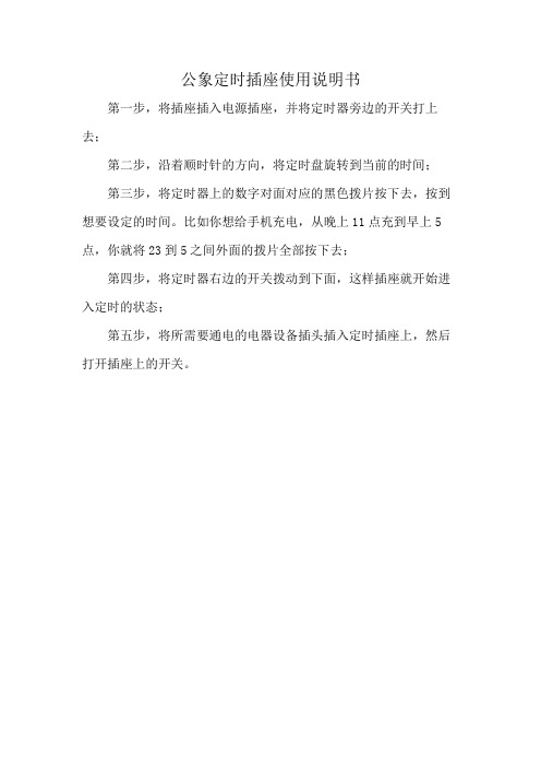
公象定时插座使用说明书
第一步,将插座插入电源插座,并将定时器旁边的开关打上去;
第二步,沿着顺时针的方向,将定时盘旋转到当前的时间;
第三步,将定时器上的数字对面对应的黑色拨片按下去,按到想要设定的时间。
比如你想给手机充电,从晚上11点充到早上5点,你就将23到5之间外面的拨片全部按下去;
第四步,将定时器右边的开关拨动到下面,这样插座就开始进入定时的状态;
第五步,将所需要通电的电器设备插头插入定时插座上,然后打开插座上的开关。
公牛usb闹钟插座 说明书
公牛usb闹钟插座说明书
插座是每一个家庭中必不可少的用品之一。
而市面上存在的插座都是各式各样以及各种各样的品牌。
其中有一个口碑很好的品牌是公牛牌插座。
那么在大家日常生活中使用的时候有没有遇到一些使用误区呢?下面就跟着小编一起来看看吧。
公牛牌插座
很多家庭在安装插座时,觉得太高有碍美观,会装在较低的隐蔽位置。
但中国科学院电工研究所夏东博士表示,这样容易在拖地时,让水溅到插座里,从而导致漏电事故。
业内规定,明装插座距地面最好不低于1.8米;暗装插座距地面不要低于0.3米。
厨房和卫生间的插座应距地面1.5米以上,空调的插座至少要2米以上。
电源导线必须使用铜线横截面。
如果住的是旧房子,一定要把原来的铝线换成铜线。
因为铝线极易氧化,接头处容易打火。
曾有调查显示,使用铝线的住宅,电气火灾发生率为铜线的几十倍。
另外,很多家庭为了美观,会采用开槽埋线、暗管铺设的方式,夏东提醒,布线时一定要遵循“火线进开关,零线进灯头”的原则,还要在插座上设漏电保护装置。
万用孔插座,即插孔可同时兼容两极或三极,甚至是英标、美标、欧标这类非日常使用插头的插座。
但此类插座因插孔较大,插座接片与电器
插头接触面积过小,容易使接触片过热导致火灾事故的发生。
两芯插座从外形上看比较容易分辨,凡是插板上有三极插孔,但插座本身自带的插头上却只有两个插销的产品,都是两芯问题插座。
这类插座缺少一根地线,在使用过程中,一旦电器内部某个绝缘部件损坏,电流将会布满整个电器表面,由于电流无法通过两芯插座导入地下,极易引发触电事故。
定时开关控制器测试说明书
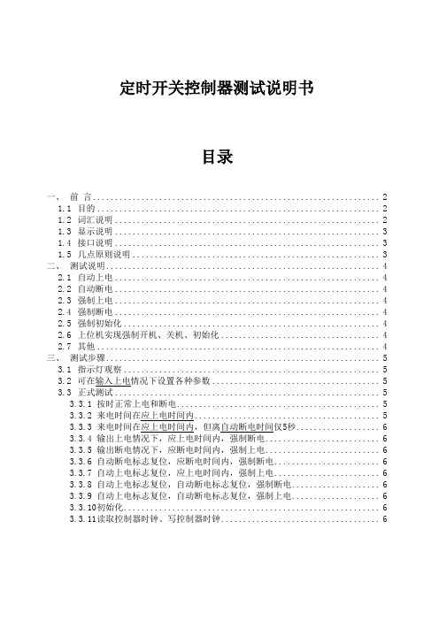
定时开关控制器测试说明书目录一、前言 (2)1.1目的 (2)1.2词汇说明 (2)1.3显示说明 (3)1.4接口说明 (3)1.5几点原则说明 (3)二、测试说明 (4)2.1自动上电 (4)2.2自动断电 (4)2.3强制上电 (4)2.4强制断电 (4)2.5强制初始化 (4)2.6上位机实现强制开机、关机、初始化 (4)2.7其他 (4)三、测试步骤 (5)3.1指示灯观察 (5)3.2可在输入上电情况下设置各种参数 (5)3.3正式测试 (5)3.3.1按时正常上电和断电 (5)3.3.2来电时间在应上电时间内 (5)3.3.3来电时间在应上电时间内,但离自动断电时间仅5秒 (6)3.3.4输出上电情况下,应上电时间内,强制断电 (6)3.3.5输出断电情况下,应断电时间内,强制上电 (6)3.3.6自动断电标志复位,应断电时间内,强制断电 (6)3.3.7自动上电标志复位,应上电时间内,强制上电 (6)3.3.8自动上电标志复位,自动断电标志复位,强制断电 (6)3.3.9自动上电标志复位,自动断电标志复位,强制上电 (6)3.3.10初始化 (6)3.3.11读取控制器时钟、写控制器时钟 (6)一、前言1.1 目的实现交流220V市电的定时开关,可编程修改各参数,特殊情况下可强行开关。
主要用于控制自助打印机系统。
1.2 词汇说明标准时钟:准确时间,通常指上位机时间。
控制器时钟:定时开关控制器时间。
通常以上位机时间来校正(开机时和关机时由上位机主动操作)。
输入上电:是指输入端与交流220V市电连接。
输入断电:是指输入端未与交流220V市电连接。
注:以下所有说明在未指明情况下皆指输入上电情况下。
输出上电:是指输出端与输入端导通,即输入端有电时输出端即有电。
输出断电:是指输出端与输入端隔离,即即使输入端有电输出端也没电。
自动上电时间:每天自动上电时间(默认值:08:00)。
自动断电时间:每天自动断电时间(默认值:18:00)。
- 1、下载文档前请自行甄别文档内容的完整性,平台不提供额外的编辑、内容补充、找答案等附加服务。
- 2、"仅部分预览"的文档,不可在线预览部分如存在完整性等问题,可反馈申请退款(可完整预览的文档不适用该条件!)。
- 3、如文档侵犯您的权益,请联系客服反馈,我们会尽快为您处理(人工客服工作时间:9:00-18:30)。
型号:GN-D-1 20时间段循环周期7天
规格:10A 250V 电子式定时器
本产品可以在无人值守的情况下,自动周期性通断电源,控制电器设备的运行,可起到节能环保,降低成本,延长电器寿命的作用.
使用范围1:在实行峰谷用电价差的地区,可使大功率电器在低价时段自动运行.
型号:GN-D-1 20时间段循环周期7天
规格:10A 250V 电子式定时器
本产品可以在无人值守的情况下,自动周期性通断电源,控制电器设备的运行,可起到节能环保,降低成本,延长电器寿命的作用.
使用范围1:在实行峰谷用电价差的地区,可使大功率电器在低价时段自动运行.
2用于控制需要定时开,关的电器.比如热水器,空调,饮水机,电饭煲,广告照明灯等.
3:用于控制通电时间长短.比如电动自行车电池,手机电池,蓄电池的充电.
4:需频繁通断的用电场合.比如花圃,草坪的间歇喷灌,鱼缸的周期性增氧,过滤等
键面分布:时钟键,设定键,模式键,清除键,星期键,小时键,分钟键,复位键,
二.初始设置
1.设置时间显示模式.
(1)同时按住时间键和星期键可设定星期. 变化为:MO-TU-WE-TH-FR-SA-SU 按住不放,星期连续变化4次/秒.
(2)同时按住时钟键和小时键可设定小时. 按住不放,小时连续变化4次/秒.
(3)同时按住时钟键和分钟键可设定分钟. 按住不放,分钟连续变化4次/秒.
(4)按住时钟键3秒,时钟显示增加1小时(夏令时显示),此时,显示屏上有"+1H"显示,再按住3秒恢复正常时间显示,"+1H"标志消失(夏令时取消)
2.当前时间校准.
(1)按住时间键不动;
(2)同时再按小时键即可调整时间小时显示,点按每次增加一小时,长按可进行快速调整;
(3)采用同样的方式可调整分钟和星期的显示
3控制模式切换
在时钟状态下连续按模式键,液晶显示屏的左边将循环显示AUTO OFF(自动关),ON(手动开),AUTO ON(自动开),OFF(手动关).
三.定时开、关的设置
1.按设定键,进入第1个时间段的通电时间设定
闹钟:若二十秒内没有进行任何操作,定时器会自动恢复到时间校准状态。
此时如需要设定开关时间,必须重新设定键。
(1)设置定时开通的时间:分别点按小时键、分钟键可设置开始通电的时间。
闹钟:长按小时键、分钟键可进行快速调整。
(2)设置循环模式:本产品的定时开、关以一星期为周期进行循环,共有下列15种模式可以选择,液晶显示:
模式1:MO(表示每周一)
模式2:TU(表示每周二)
模式3:WE(表示每周三)
模式4:TH(表示每周四)
模式5:FR(表示每周五
模式6:SA(表示每周六)
模式7:SU(表示每周日)
模式8:MO,TU,WE,TH,FR,(表示每周一,二,三,四,五)
模式9:SA,SU(表示每周六,日)
模式10:MO,TU,WE ,TH,FR,SA(表示每周一,二,三,四,五,六)
模式11:MO,WE,FR(表示每周一,三,五)
模式12:TU,TH,SA(表示每周二,四,六)
模式13:MO,TU,WE(表示每周一,二,三)
模式14:TH,FR,SA(表示四,五,六)
模式15:MO,TU,WE,TH,FR,SA,SU(自动表示)
连续点按星期键,液晶会顺序显示十五种循环模式,用户可以根据需要选择每周的任意一天或几天的相同时段执行定时开关程序。
闹钟:长按星期键可进行快速调整;
按清除键可将当前设置的时间和循环模式清除,再按又恢复到清除前的设定。
2.再按设定键进入第1个时间段的断电时间设定,操作方法与上述通电时间的设定相同.到此第1个时间段的定时开、关时间设定完毕。
3.继续按设定键,进入下一个时间段的定时开、关时间设定,重复以上操作。
本产品最多可设置20个时间段。
注意:任何情况下,按复位键可使程序重新启动,恢复到定时器出厂的设置,所有的用户设置将被清除。
四、应用实例
某双职工家庭,上班时周一到周五的三餐都回家吃饭,由于使用电饭锅做饭,早餐和中餐经常感到时间仓促。
后来他们选用了公牛定时转换器,自动控制电饭煲的开关,回到家饭就已经做好了,节省出不少宝贵的时间!
设置步骤
(一)计划
第1段:星期一~星期五每天6:45开、7:15关;
第2段:星期一~星期五每天11:30开、12:00关。
晚餐因时间充足,可灵活掌握,不设定时间控制。
(二)具体操作
(1)按照“初始设置”的步骤调准当前时间
(2)按设定键:液晶应显示时间段“1”、“NO”的字样;
(3)调整定时开的分钟:按分钟键设定分钟为45;
(4)调整定时开的小时:按小时键设定小时为6;
(5)调整定时开的星期:连续按星期键直至液晶显示星期模式为MO,TU,WE,TH,FR,液晶显示.
(6)在按设定键,液晶显示时间段“1”,“OFF”的字样;
(7)调整定时关的分钟:按分钟键设定分钟为15;
(8)调整定时关的小时:按小时键设定小时为7;
(9)调整定时关的星期:连续按星期键使液晶显示星期模式为MO,TU,WE,TH,FR,液晶显示。
(10)按照类似方法可完成第2个时间段定时开、关的设定,定时开、关时间设定完成。
(11)将公牛定时转换器插在电源插座上,注意此时通电指示灯应处于熄灭状态,否则请按照“初始设置”的操作将控制模式调整为AUTO OFF;
(12)将电饭煲的插头插入定时转换器插孔,到设定时间电饭煲就会自动地开关了。
五、内置电池维护
1.未插入电源时,本产品内置的扣式充电电池向内部微电路供电,以保留设置和时间的运行;插入电源后本产品会自动充电,充电8小时可保留设置1个月。
2.如果长期不使用,电池电量将被耗尽,液晶将无法显示,在充电4小时后显示即可恢复,但原有设置将被清除。
3.为使电池达到最佳性能,第一次使用(或长期不用)的定时转换器最好先插入电源充电10~16小时,然后再使用.
六、注意事项
1.此定时器属电子产品,不能用作儿童玩具.
2.请在室内干燥的环境下使用.
3.本品所接电器功率总和不得超过额定功率.
4.请勿私自拆卸或变换产品内部结构.
七、技术参数
额定电压:250V 额定电流:见产品名牌
最多设定段位:20个循环周期:7天
开\关最小间隔:1分钟工作温度:-10~40度
内置电池:NiMH 1.2V
2用于控制需要定时开,关的电器.比如热水器,空调,饮水机,电饭煲,广告照明灯等. 3:用于控制通电时间长短.比如电动自行车电池,手机电池,蓄电池的充电.
4:需频繁通断的用电场合.比如花圃,草坪的间歇喷灌,鱼缸的周期性增氧,过滤等。