海尔-FCD-JTHML-说明书
海尔-FCD-JTHML-说明书(新)
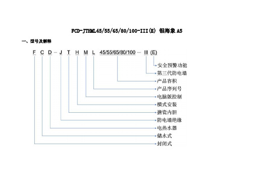
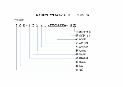
FCD-JTHML45/55/65/80/100-III(E) 银海象A5一、型号及解释二、产品外观、内部结构、随机附件产品外观:内部结构:A.热水出口 B冷水进口 C加热管 D搪瓷内胆 E进水管 F出水管 J 控制板 K镁棒随机附件:三、电脑板操作控制面板介绍:1.工作模式选择键(中/保键)2.调节键3.功能键4.开/关键5.夜电选定图案6.预约2选定图案7.功率指示图案8.时钟指示数码9.预约1选定图案 10.中温保温选定图案 11.温度指示条安装好后,首次使用因内胆无水,必须先开启自来水进水阀门,待内胆水满,出水口连续出水后,关闭阀门,检查各接口处有无漏水,插上电源。
1、开机:首次使用时,显示屏仅时钟点亮,时钟显示12:00并开始走时,进入待机状态,按一下“开/关”键,进入上次设定工作状态,相应的指示灯点亮。
2、功率选择:开机状态下,连续按“功能”键进入功率选择状态,按“调节”键可在800W、1200W、2000W三档功率间选择,当选定加热功率为800W时,功率指示图标中的半圆点亮,上层加热管单独启动。
当选定加热功率为1200W时,功率指示图案中的半圆与周围光芒交替点亮,下层加热管单独启动。
当选定2000W时,功率指示图案的半圆及周围光芒共同点亮,上下加热棒同时加热。
下图中,加热功率为2000W,时钟当前时间为12:10,设定最高加热温度为75℃的即时加热模式。
3、温度设置:开机状态下,按“功能”键可进入温度设置状态,温度值指示条快速闪烁,按“调节”键调整到要设定的温度(温度数值在35-75℃内以5℃进行变化),此时可继续按“功能”键进入时钟设置或不操作6秒后机器自动确认并退出设置。
注:在非设置状态时,显示屏动画交替显示实际水温与设置温度。
当温度灯从35℃向右移动时表示正在显示实际温度,在到达实际水温后一起熄灭。
当温度灯从75℃向左移动时表示正在显示设置温度,在到达设定温度后一起熄灭。
设定温度与实际温度交替显示。
海尔家用电器产品说明书.pdf_1719182771.4172356

This is the safety alert symbol. It is used to alert you topotential personal injury hazards. Obey all safety messagesthat follow this symbol to avoid possible injury or death.Indicates a hazardous situation which, if not avoided,will result in death or serious injury.Indicates a hazardous situation which, if not avoided,could result in death or serious injury.Indicates a hazardous situation which, if not avoided,could result in minor or moderate injury.Addresses practices not related to personal injury.Read all safety warnings and instructions.Failure to follow the warnings and instructions may result in serious injury.Save all warnings and instructions for future reference.The warnings and precautions discussed in this manual cannot cover allpossible conditions and situations that may occur. It must be understoodby the operator that common sense and caution are factors which cannotbe built into this product, but must be supplied by the operator.Work area1.Turn off the engine,set the parking brake, and block thetires before working on a vehicle. 2.Keep the work area clean andwell lighted. Cluttered benchesand dark areas increase therisk of injury to persons.3.Keep bystanders and children awaywhile operating the tool. Distractionscan result in loss of control of the tool.Page 2For technical questions, please call 1-800-444-3353.Items 44899, 44900Personal safety1.Stay alert. Watch what youare doing and use commonsense when operating the tool.Do not use the tool while tiredor under the influence of drugs,alcohol, or medication.A momentof inattention while operating the toolincreases the risk of injury to persons.2.Dress properly. Do not wear looseclothing or jewelry. Contain long hair.Keep hair, clothing, and glovesaway from moving parts.Loose clothes, jewelry, or long hairincreases the risk of injury to persons asa result of being caught in moving parts.e safety equipment.Wear ANSI-approved safety gogglesand heavy-duty work gloves during use.Tool use and care1.Do not force the tool. Use the correcttool for the application. The correcttool will do the job better and safer atthe rate for which the tool is designed.2.Store the tool when it is idle out ofreach of children and other untrained persons. A tool is dangerous inthe hands of untrained users.3.Check for misalignment or bindingof moving parts, breakage ofparts, and any other conditionthat affects the tool’s operation.If damaged, have the tool servicedbefore using. Many accidents arecaused by poorly maintained tools.e only accessories that areidentified by the manufacturerfor the specific tool model.Use of an accessory not intendedfor use with the specific tool model,increases the risk of injury to persons.5.Avoid off-center loads. If the Pumpseems unusually hard to operate,immediately stop. Adjust the Ram toeliminate or diminish an off-off center load.The Flange Base and Flange Headmust only be used together toprevent an off-center load.6.Protect the Hose. Do not dropheavy objects on the Hose.Avoid kinks in the Hose.Maintain proper clearance to avoiddamage to the Hose and Couplers.7.Inspect repair before using vehicle.Repairs to structural or frame membersmust be inspected by a qualifiedtechnician to ensure that thestructure is still strong enoughto safely fulfill its function.Service1.Tool service must be performedonly by qualified repair personnel.2.When servicing a tool, use onlyidentical replacement parts.Use only authorized parts.SAVE THESE INSTRUCTIONS.Page 3 For technical questions, please call 1-800-444-3353.Items 44899, 44900Model4489944900Ram Capacity 4 Tons2 Tons w/ extensions10 Tons5 Tons w/ extensionsRam Travel5″6″Extension Pole Length4′ 512⁄″ Maximum5′ MaximumSpreader Capacity 12⁄ Ton3-34⁄″ Maximum Opening12⁄ Ton3-34⁄″ Maximum OpeningHose Length6′6′Read the ENTIRE IMPORTANT SAFETY INFORMATION section at thebeginning of this document including all text under subheadings thereinbefore set up or use of this product.Ram Attachments1.The ns connect in differentExtensionscombinations to reach desired lengths.2.The tor is used to connectMale Connectorthe female end of the Ram to a Base.3.The Flat Base is used on the stationaryside to spread out the force of the Ram.4.The 90° V Base is used to offset theforce of the Ram when there is not astraight line between the stationaryside and the damaged side, orto spread out force on curved surfaces.5.The ad is used on theCap Headpushing end to prevent slipping.6.The ad is used for poppingRubber Headdents out of sheet metal such asdoors or body panels and to minimizedamage to the work surface.7.The ad is used to repairWedge Headsmall dents and areas locatedin angles and tight spaces.8.The Flange Base and Flange Headare used together to allow spreadingin areas that the Ram cannot fit into. Note: The Flange Base andFlange Head must only be used together to prevent an off-center load.Page 4For technical questions, please call 1-800-444-3353.Items 44899, 44900Page 5For technical questions, please call 1-800-444-3353.Items 44899, 44900Ram SetupNote:When positioning the Ram use a smaller attachment on the side that is to be bent instead of the stationary side. If the stationary side is indanger of being bent or damaged, place a block of wood or other materialbehind the Flat Base to distribute pressure over a greater area.1.Clean the end of the Hose and theinlet on the Ram. Unscrew andsave the End Plugs located onthe end of the Hose and Ram.2.Attach the Hose to the Ram.3.Assemble attachments as shown below:Male Connector Ram 90° V Base or Flat Base (install Extensions here as needed)Cap Head,Rubber Head,or Wedge Head Ram Flange Base (install Extensions here as needed)Flange Head Note: If using the Flange Base and Flange Head, thread the Flange Baseonto the Ram completely andalign the Flange Head to it.Spreader SetupThe der is used when the RamSpreader is too long to fit between the stationaryside and the damaged area.1.Clean the end of the Hose and the inlet on the Spreader.2.Unscrew and save theEnd Plugs located on the endof the Hose and Spreader. 3.Attach the Hose to the Spreader, as shown below:PumpSpreaderHoseRead the ENTIRE IMPORTANT SAFETY INFORMATIONsection at the beginning of this manual including all textunder subheadings therein before use of this product. 1.Check the Hydraulic Fluid level, following the instructionsin the Cleaning and Maintenance section.2.Determine which direction the frame needs to be bent.3.Remove any obstructions that could be damaged or are in the way. Note: When using the Pump in a vertical position,keep the Hose end of the Pump downward.ING RAM:a.Connect the appropriate Base tothe stationary side of the Ram,and connect the appropriate headto the pushing end of the Ram. Note: When repairing larger bodypanel dents such as a dented door,fender or quarter-panel use theRubber Head on the pushing end.b.If using the Flange Base orFlange Head:Thread the Flange Base onto theRam completely and align theFlange Head to it. The Flange Baseand Flange Head must only be usedtogether to prevent off-center load.c.Position the Ram so that the Baseis resting against a frame memberopposite the damaged area. It mustalso be in line with the direction inwhich the damaged area needs tobe pushed. The vehicle body partmust be stronger than the areato be bent or it may be damaged.A block of wood or a towel maybe used to protect the body part.d.Aim the pushing end towards thearea that needs to be repaired, andslowly apply pressure with the Pump. Note: To prevent damage,do not overextend the Ram.ING SPREADER:a.Place the Spreader so that thehinged (pushing) arm is restingagainst the part to be movedand the stationary arm is resting against a non-movable base.b.Carefully hold the Spreader inposition and apply pressurewith the Pump.5.Once both ends have made contact, move as far away as possible and continue toslowly apply pressure to the damaged area until the desired bend has been made.CAUTION! Keep hands away from contact areas and tight spaces.The tool may slip and cause injury.6.When the damaged area has been bent to the desired position,slowly turn the Release Valve counterclockwise to release thehydraulic pressure and remove the Ram or Spreader.7.Clean all hydraulic ports and cover them with clean End Plugs.Page 6For technical questions, please call 1-800-444-3353.Items 44899, 449001.Keep the surface of this tool and itsaccessories free of hydraulic fluid andgrease. Use only a mild detergent anddamp cloth when cleaning. Do not usea flammable or combustible solventto clean this tool or its accessories.2.Before each use, examine the generalcondition of the tool and its accessories.Check for loose components,misalignment, binding of moving parts,broken parts and any other conditionthat may affect its safe operation.Do not use a damaged tool orits damaged accessories.3.Keep hydraulic connections clean.Clean all hydraulic ports and replaceDust Covers immediately after use.4.Store the Pump with theRelease Valve open.Filling and Bleeding Hydraulic FluidIf the Pump operation feels spongy, or the Ram lowers while the Release Valve is closed, there may be air in the Pump. Bleed the Pump as follows:1.Set Pump flat on a level surface.2.Remove the Fill Screw.The Seal Ring should come off with it.3.The fluid level should be nearthe bottom of the opening.If required,add high gradehydraulic fluid.4.Make sure the Seal Ring is still inplace around the Fill Screw andthread the Fill Screw into the Pumpsecurely. Do not use thread seal tape.5.Firmly close the Release Valveby turning it clockwise.6.Press the tip of the Coupleragainst a hard surface andpump the pump handle.7.Continue pumping, until thehydraulic fluid coming out the end ofthe Coupler tip is free of air bubbles.8.Recheck the fluid level andadd fluid if necessary.9.Turn the Release Valvecounterclockwise to releasethe pressure in the Pump and Hose.Changing Hydraulic Fluid1.Change the hydraulic fluid yearly.2.Remove the Fill Screw and tilt thePump to drain out the old fluid.3.Refill the hydraulic fluid and bleedthe system several times to ensureall air is out of the system.Page 7For technical questions, please call 1-800-444-3353. Items 44899, 44900Page 8For technical questions, please call 1-800-444-3353.Items 44899, 4490044900 Main Parts List and Assembly Diagram Part Description Qty 3Pump Handle 14Hose 15Ram 16Pump 17Male Connector 18Flange Head 19Flange Base 110Wedge Head 11190° V Base 1Part Description Qty 12Flat Base 113Rubber Head 114Spreader 115Cap Head 1165″ Extension 11710″ Extension 11818″ Extension 11927″ Extension 1181651713147109151112843619PLEASE READ THE FOLLOWING CAREFULLYTHE MANUFACTURER AND/OR DISTRIBUTOR HAS PROVIDED THE PARTS LIST AND ASSEMBLY DIAGRAM IN THIS DOCUMENT AS A REFERENCE TOOL ONLY . NEITHER THE MANUFACTURER OR DISTRIBUTOR MAKES ANY REPRESENTATION OR WARRANTY OF ANY KIND TO THE BUYER THAT HE OR SHE IS QUALIFIED TO MAKE ANY REPAIRS TO THE PRODUCT, OR THAT HE OR SHE IS QUALIFIED TO REPLACE ANY PARTS OF THE PRODUCT. IN FACT, THE MANUFACTURER AND/OR DISTRIBUTOR EXPRESSLY STATES THAT ALL REPAIRS AND PARTS REPLACEMENTS SHOULD BE UNDERTAKEN BY CERTIFIED AND LICENSED TECHNICIANS, AND NOT BY THE BUYER. THE BUYER ASSUMES ALL RISK AND LIABILITY ARISING OUT OF HIS OR HER REPAIRS TO THE ORIGINAL PRODUCT OR REPLACEMENT PARTS THERETO, OR ARISING OUT OF HIS OR HER INSTALLATION OF REPLACEMENT PARTS THERETO.Page 9For technical questions, please call 1-800-444-3353.Items 44899, 44900Record Product’s Serial Number Here:Note: If product has no serial number, record month and year of purchase instead.Note: Some parts are listed and shown for illustration purposes only, and are notavailable individually as replacement parts.44900 Parts List and Assembly Diagram A - Ram (5)Part Description 1ADust Cap 2ACoupling 3ACoupling Ring 4AC Snap Ring 5ABushing 6A Protecting Cap 7A Ring 8A Screw 9ASpring 10AC Clip 11AWasher 12ASpreader 13ACap 14ACap 15ACap 16ABushing 17ABearing 18AWasher 19ARam 20A Cylinder 4A 18A 6A 7A 19A 17A16A15A13A14A13A12A 1A 20A8A 5A 9A10A 11A 2A3A8APage 10For technical questions, please call 1-800-444-3353.Items 44899, 4490044900 Parts List and Assembly Diagram B - Spreader (14)11B 10B 9B 12B 13B 8B 7B 6B 5B 4B 3B 2B 1B Part Description 1BDust Cap 2BO-ring 3BCoupler 4BCoupler Ring 5BEnd Plug 6BWasher 7B Cup Seal Part Description8B Piston 9B C-clip 10B Pivoting Pin 11B Pushing Arm 12B Spring 13B Stationary ArmPart Description 1C Screw (Safety Valve) 2C Plastic Cap3C Screw4C O-ring Seal5C Spring6C Stem7C Ball Valve8C Washer9C Valve10C Release Valve11C Spring12C Ball Valve13C Fill Screw14C Ball Valve Part Description15C End Plug16C Coupling17C Spring18C Hose19C Fluid Fitting20C Grip21C Handle22C Circle Clip23C Pivot Pin Arm24C Pivot Pin Arm25C Pivot Pin Arm26C Plunger27C Washer28C SealPart Description29C Filter Ring30C Cylinder31C Washer32C Seal33C Spacer34C O-ring35C O-ring36C Bolt37C Pump Foot38C Screw39C Reservoir40C Seal41C Filter42C Housing44900 Parts List and Assembly Diagram C - Pump20C38C 13C34C 42C1C7C6C4C3C2C25C22C27C29C9C37C32C30C28C26C18C24C8C5C39C36C35C41C40C14C33C10C11C12C17C31C19C15C16C21C23CPage 11 For technical questions, please call 1-800-444-3353.Items 44899, 4490044899 Main Parts List and Assembly Diagram13143816129110172 76541511Part Description Qty1Pump12Ram13Hose1419-1/2” Extension1516-1/2” Extension168-1/2” Extension175” Extension183-1/4” Extension19Cap Head1Part Description Qty10Spreader1112-3/4” Rubber Head112Wedge Head11390° V Base114Flange Head115Flange Base116Male Connector117Flat Base1Page 12For technical questions, please call 1-800-444-3353.Items 44899, 44900Page 13For technical questions, please call 1-800-444-3353.Items 44899, 4490044899 Parts List and Assembly Diagram A - Spreader (10)13A12A 10A11A9A8A 7A 6A 5A4A 3A 2A 1APartDescription 1A Dust Cap 2A O-ring 3A Coupler4A Coupler Ring 5A End Plug 6A Washer 7ACup SealPartDescription8A Piston9A Stationary Arm 10A C-clip 11A Spring12A Pivoting Pin 13APushing ArmPage 14For technical questions, please call 1-800-444-3353.Items 44899, 4490044899 Parts List and Assembly Diagram B - Ram (2)PartDescription1B End Plug 2B O-ring 3B Coupler4B Coupler Ring 5B Screw 6B Cylinder 7B Spring 8B Ring9B Protector Cap10B Circle Clip 11B Washer 12B “U” Seal13B Backup Ring 14B Bushing 15B Bearing 16B Ram 17B Washer 18B C-clip 19BBushing1B2B3B4B5B6B5B19B 7B8B9B10B11B12B13B14B15B16B17B18BPart Description 1C Screw (Safety Valve) 2C Plastic Cap3C Screw4C O-ring Seal5C Spring6C Stem7C Ball Valve8C Washer9C Valve10C Release Valve11C Spring12C Ball Valve13C Fill Screw14C Ball Valve Part Description15C End Plug16C Coupling17C Spring18C Hose19C Fluid Fitting20C Grip21C Handle22C Circle Clip23C Pivot Pin Arm24C Pivot Pin Arm25C Pivot Pin Arm26C Plunger27C Washer28C SealPart Description29C Filter Ring30C Cylinder31C Washer32C Seal33C Spacer34C O-ring35C O-ring36C Bolt37C Pump Foot38C Screw39C Reservoir40C Seal41C Filter42C Housing44899 Parts List and Assembly Diagram C - Pump20C38C 13C34C 42C1C7C6C4C3C2C25C22C27C29C9C37C32C30C28C26C18C24C8C5C39C36C35C41C40C14C33C10C11C12C17C31C19C15C16C21C23CPage 15 For technical questions, please call 1-800-444-3353.Items 44899, 44900Harbor Freight Tools Co. makes every effort to assure that its products meet high qualityand durability standards, and warrants to the original purchaser that this product is free from defects in materials and workmanship for the period of 90 days from the date of purchase.This warranty does not apply to damage due directly or indirectly, to misuse, abuse, negligence or accidents, repairs or alterations outside our facilities, criminal activity, improper installation, normal wear and tear, or to lack of maintenance. We shall in no event be liable for death, injuries to persons or property, or for incidental, contingent, special or consequential damages arising from the use of our product. Some states do not allow the exclusion or limitation of incidental or consequential damages, so the above limitation of exclusion may not apply to you. THIS WARRANTY IS EXPRESSLY IN LIEU OF ALL OTHER WARRANTIES, EXPRESS OR IMPLIED, INCLUDING THE WARRANTIES OF MERCHANTABILITY AND FITNESS.To take advantage of this warranty, the product or part must be returned to us with transportation charges prepaid. Proof of purchase date and an explanation of the complaint must accompany the merchandise. If our inspection verifies the defect, we will either repair or replacethe product at our election or we may elect to refund the purchase price if we cannot readily and quickly provide you with a replacement. We will return repaired products at our expense, but if we determine there is no defect, or that the defect resulted from causes not withinthe scope of our warranty, then you must bear the cost of returning the product.This warranty gives you specific legal rights and you may alsohave other rights which vary from state to state.3491 Mission Oaks Blvd. • PO Box 6009 • Camarillo, CA 93011 • (800) 444-3353。
海尔FCD-JTHML说明书
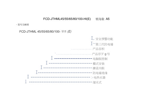
FCD-JTHML45/55/65/80/100-HI(E) 银海象A5、型号及解释FCD-JTHML 45/55/65/80/100- 111 (E)L安全预警功能I~第三代防电墙-------------- 产品容积h------------------------ 产品序歹g号I --------------------- 电脑版控制I ------------------------ 横式安装I --------------------------- 搪瓷内胆I ------------------------------ 防电墙绝缘I --------------------------------- >电热水器1 ----------------------------------- 储水式FCD-JTHML45/55/65/80/100-HI(E) 银海象A5 ------------------------------------------------ 封闭式、产品外观、内部结构、随机附件产品外观:内部结构:A.热水出口B冷水进口C加热管D搪瓷内胆E进水管F出水管J控制板K镁棒三、电脑板操作控制面板介绍:■1■2■3 4-逬入上次掉电割工作状态—温虔设涔揀町以壷离加集盘度设定n 神的小时设昇也空校止时神的屮时数妈 时神的分御设弹"勒狡正时钟的分钟数码F 约1的那时设袴泌^迥节预约1的小时数码F 约1的分御设 踏也调节伙约1的井钟数昭 一预约2的小时设聲也调节预的2的小时数码 一预约2的分钟设即调节预豹2的分神数码 三档功率选 (SQOW/1200W/2000W) 远程选撵加博所需功率「中温保温 「夜电-中/保键一顶约1-颅釣2-预约T+预约2-即时加热/保温「开械歼/关題--关机1.工作模式选择键(中/保键)2.调节键3.功能键4.开/关键5.夜电选定图案6.预约2选定图案7.功率指示图案8.时钟指示数码9.预约1选定图案10.中温保温选定图案11.温度指示条安装好后,首次使用因内胆无水,必须先开启自来水进水阀门,待内胆水满,出水口连续出水后,关闭阀门,检查各接口处有无漏水,插上电源。
海尔冰柜说明书之令狐采学创编
海尔冰箱bcd 195wt,矛盾的说明书令狐采学624 17:46冰箱内的温度是通过温控器调节旋钮①来调节的。
旋钮上的刻度“0”是关机位置,“1,2,3,4,5,6,7”不代表具体的温度,数字越小,箱内温度越高;数字越大,则箱内温度越低。
推荐:1~3档环境温度≥30℃3~5档环境温度16~30℃5~7档环境温度≤16℃外界温度高室内冰箱才应该调低温度,比如外界30度冰箱内调为5度。
如果冬天外界温度15度,冰箱要调成0度。
这是什么逻辑?难道冰箱里温度越低越省电?那这样一年四季调零度好了624 19:17 满意回答首先要解释一下机械冰箱的控温原理,机械冰箱是通过冷藏室的温控器来控制整个冰箱的温度的,制冷剂从冷冻流向冷藏,再回压机.就是说,冷冻室是间接通过冷藏来控制的,冷藏温度达到后,制冷剂不再流动,冷冻室也不会再单独制冷。
明白了上面的原理后,就好解释你提的问题了.1.夏天调低档是因为节电和保护压机。
举例说,如果你夏天调到5~7档,代表冰箱冷藏要维持一个很低的温度才会停机,而夏天环境温度高,要维持这个温度很难,所以压机会一直长时间运转,不但于压机不利,而且也不节能。
2.冬天调高档是为了保持冷冻室内食物不容易变坏.冬天,环境温度低,如果我们设定为低档,冰箱冷藏很容易就达到设定档位对应的温度,所以压机会长时间不运转,而这个结果就导致了冷冻室温度上升,我们知道,一般冷冻室温度都在12度以下,在这个温度下很多食物可存放很久,而如果压机很少运转的话,就很难维持这个温度了。
所以我们要设定为高档.这也是为什么冬天要求打开冷藏室的温度补偿开关的原因,就是想让冷藏室传感器附近的温度升高,这样压机就会启动,来维持冬天的时候冷冻室的温度.如果理解了我上面的话,你就明白说明书的意思了,说明书并没有错.624 18:03没错的,冰箱其实就是一个能量转换过程,如果室内外温度相差太大,冰箱是很难进入最佳工作状态。
如果外界温度为35度,你想要冰箱内达到18度,可以达到,但是你需要压缩机不停机长时间运转才行。
海尔FCD-JTHML说明书..
65 220V~/50Hz 800/1200/2000
0.75
FCD-JTHML80-II (E)
80 220V~/50Hz 800/1200/2000
0.75
FCD-JTHML100-II (E) 100 220V~/50Hz 800/1200/2000
0.75
75
IPX4
24
75
IPX4
28
75
2000W
导致热水器到达预约时间仍未能达到设定温度,机器也将自动延时半小时并停止。
7、夜电设置:
开机状态下,连续按“中 / 保”键,可进入夜电工作模式。加热时间为
00:00-06:00 ,加热功率与最高加热温度可人工设置调节。
8、运行模式选择:
开机状态下,每按“中 / 保”键一次,系统将在中温保温、夜电、预约
一、型号及解释
FCD-JTHML45/55/65/80/100-III(E) 银海象 A5
二、产品外观、内部结构、随机附件
产品外观:
内部结构:
A. 热水出口 B 冷水进口 C 加热管 D 搪瓷内胆 E 进水管 F 出水管 J 控制板 K 镁棒 随机附件:
产品型号
电热水 安全阀 器(台) (个)
喷头、软 管、支座 (套)
5、中温保温设置:
在开机状态下,连续按“中 / 保”键,可进入中温保温工作模式。机器自动在 新开始加热。
注:默认最高加热温度为 40℃不可调,适用于少量用水需求,不适合淋浴。
35℃ -40 ℃间选择最节能的保温温度,水温下降至
35℃时。机器自动重
6、预约时间设置:
可设置两档用水时间,设置时间以电脑板时间为基准。在预约模式下,系统默认加热功率为 例:设置预约 1 用水时间为 10:00 。
海尔电子发展有限公司智能加热饮水器用户手册说明书

2. Add rinse aid up to the max mark.
max
3. Close the lid of the dispenser for rinse aid. a The lid clicks into position.
washers. Remove large remnants of food from 3. Switch on the appliance .
the tableware. Check that the spray arms can ro-
4. Select the programme. 5. Start the programme . 6. Remove the tableware at the end of the pro-
Programmes
The programme data has been measured in the laboratory according to European standard EN 60436. The consumption figures depend on the programme and additional function selected. The running time will change if the rinse aid system is switched off or rinse aid needs to be added.
gether and lift
1
the coarse filter
out .
Cleaning spray arms
海尔冰柜说明书
海尔冰箱bcd 195wt,矛盾的说明书2009-6-24 17:46 冰箱内的温度是通过温控器调节旋钮①来调节的。
旋钮上的刻度“0”是关机位置,“1,2,3,4,5,6,7”不代表具体的温度,数字越小,箱内温度越高;数字越大,则箱内温度越低。
推荐:1~3档环境温度≥30℃3~5档环境温度16~30℃5~7档环境温度≤16℃外界温度高室内冰箱才应该调低温度,比如外界30度冰箱内调为5度。
如果冬天外界温度15度,冰箱要调成0度。
这是什么逻辑?难道冰箱里温度越低越省电?那这样一年四季调零度好了2009-6-24 19:17 满意回答首先要解释一下机械冰箱的控温原理,机械冰箱是通过冷藏室的温控器来控制整个冰箱的温度的,制冷剂从冷冻流向冷藏,再回压机.就是说,冷冻室是间接通过冷藏来控制的,冷藏温度达到后,制冷剂不再流动,冷冻室也不会再单独制冷。
明白了上面的原理后,就好解释你提的问题了.1.夏天调低档是因为节电和保护压机。
举例说,如果你夏天调到5~7档,代表冰箱冷藏要维持一个很低的温度才会停机,而夏天环境温度高,要维持这个温度很难,所以压机会一直长时间运转,不但于压机不利,而且也不节能。
2.冬天调高档是为了保持冷冻室内食物不容易变坏.冬天,环境温度低,如果我们设定为低档,冰箱冷藏很容易就达到设定档位对应的温度,所以压机会长时间不运转,而这个结果就导致了冷冻室温度上升,我们知道,一般冷冻室温度都在-12度以下,在这个温度下很多食物可存放很久,而如果压机很少运转的话,就很难维持这个温度了。
所以我们要设定为高档.这也是为什么冬天要求打开冷藏室的温度补偿开关的原因,就是想让冷藏室传感器附近的温度升高,这样压机就会启动,来维持冬天的时候冷冻室的温度.如果理解了我上面的话,你就明白说明书的意思了,说明书并没有错. 2009-6-24 18:03 没错的,冰箱其实就是一个能量转换过程,如果室内外温度相差太大,冰箱是很难进入最佳工作状态。
海尔FCD-JTHML说明书
FCD-JTHML45/55/65/80/100-III(E) 银海象A5一、型号及解释二、产品外观、内部结构、随机附件产品外观:内部结构:A.热水出口 B冷水进口 C加热管 D搪瓷内胆 E进水管 F出水管 J 控制板 K镁棒随机附件:三、电脑板操作控制面板介绍:1.工作模式选择键(中/保键)2.调节键3.功能键4.开/关键5.夜电选定图案6.预约2选定图案7.功率指示图案8.时钟指示数码9.预约1选定图案 10.中温保温选定图案 11.温度指示条安装好后,首次使用因内胆无水,必须先开启自来水进水阀门,待内胆水满,出水口连续出水后,关闭阀门,检查各接口处有无漏水,插上电源。
1、开机:首次使用时,显示屏仅时钟点亮,时钟显示12:00并开始走时,进入待机状态,按一下“开/关”键,进入上次设定工作状态,相应的指示灯点亮。
2、功率选择:开机状态下,连续按“功能”键进入功率选择状态,按“调节”键可在800W、1200W、2000W三档功率间选择,当选定加热功率为800W时,功率指示图标中的半圆点亮,上层加热管单独启动。
当选定加热功率为1200W时,功率指示图案中的半圆与周围光芒交替点亮,下层加热管单独启动。
当选定2000W时,功率指示图案的半圆及周围光芒共同点亮,上下加热棒同时加热。
下图中,加热功率为2000W,时钟当前时间为12:10,设定最高加热温度为75℃的即时加热模式。
3、温度设置:开机状态下,按“功能”键可进入温度设置状态,温度值指示条快速闪烁,按“调节”键调整到要设定的温度(温度数值在35-75℃内以5℃进行变化),此时可继续按“功能”键进入时钟设置或不操作6秒后机器自动确认并退出设置。
注:在非设置状态时,显示屏动画交替显示实际水温与设置温度。
当温度灯从35℃向右移动时表示正在显示实际温度,在到达实际水温后一起熄灭。
当温度灯从75℃向左移动时表示正在显示设置温度,在到达设定温度后一起熄灭。
设定温度与实际温度交替显示。
海尔空调系列产品技术参数手册说明书

2.2PerformanceRotational speed (50 Hz supply)0 to 2900 r.min-1Rotational speed (60 Hz supply)0 to 3500 r.min-1Total pressure (single-stage backing pump,with gas-ballast) 2 x 10⁻²mbar absolute (2 Pa)Ultimate pressure (single-stage backingpump without gas-ballast, permanent gases) 2 x 10⁻³mbar absolute (2 x 10⁻¹Pa)Total pressure (two-stage backing pumpwith gas-ballast) 1 x 10⁻³mbar absolute (1 x 10⁻¹Pa)Maximum outlet pressure (see Section 1.2.4)1000 mbar absolute (1 x 10⁵Pa)Pressure differential across pump (determined by the hydrokinetic drive)Pump50 Hz60 HzEH2500 to 180 mbar0 to 1.8 x 10⁴Pa0 to 150 mbar0 to 1.5 x 10⁴PaEH500A0 to 110 mbar0 to 1.1 x 10⁴Pa0 to 90 mbar0 to 0.9 x 10⁴PaEH1200/1200C0 to 90 mbar0 to 0.9 x 10⁴Pa0 to 75 mbar0 to 0.75 x 10⁴PaEH2600/2600C0 to 80 mbar0 to 0.8 x 10⁴Pa0 to 67 mbar0 to 0.67 x 10⁴PaEH4200/4200C0 to 60 mbar0 to 0.6 x 10⁴Pa0 to 50 mbar0 to 0.5 x 10⁴Pa 2.3Recommended backing pumpsBecause of the flexibility of the hydrokinetic drive,there is a wide range of backing pumps whichare suitable for use with the EH Mechanical Booster pumps.Contact your supplier or BOCEdwards for advice on suitable backing pumps.2.4Connections2.4.1Vacuum connectionsInlet OutletEH250ISO63ISO40EH500A ISO100ISO63EH1200/1200C ISO160ISO100EH2600/2600C ISO160ISO100EH4200/4200C ISO250ISO1002.4.2Cooling-water connectionsInlet connection3/8inch BSP maleOutlet connection3/8inch BSP male2.4.3Coupling-cover purge connection (EH1200C/2600C/4200C only)Purge connection1/4inch compression fittingEH Mechanical Booster Pumps152.5Electrical dataNote:The motors of EH250and EH500A pumps are supplied configured for‘low voltage’operation (240V and lower),the motors of EH1200/1200C,EH2600/2600C and EH4200/4200C pumps aresupplied configured for ‘high voltage’ operation (380 V and higher): refer to Section 3.6.Number of phases3Supply voltage220-240 V/380-415 V at 50 Hz208-230 V/460 V at 60 HzVoltage tolerance±6%Full load current ratings See Table 2220 V 50 Hz 240 V50 Hz380 V50 Hz415 V50 Hz208 V60 Hz230 V60 Hz460 V60 HzEH250 & EH500A Full load (A) 6.3 5.8 3.7 3.4 6.1 5.5 2.8 Rating (kW) 1.5 1.5 1.5 1.5 1.5 1.5 1.5EH1200Full load (A)11.110.2 6.4 5.911.910.7 5.4 Rating (kW)3333333EH2600 & EH4200 (7.5 kW)Full load (A)19.818.211.510.520.918.99.5 Rating (kW)7.57.57.57.57.57.57.5EH2600 & EH4200 (11 kW)Full load (A)--21.520.7-34.817.4 Rating (kW)--1111-1111EH1200C Full load (A)--6 5.7-105 Rating (kW)--33-33EH2600C & EH4200C Full load (A)--2220-3618 Rating (kW)--1111-1111 Table 2 - Full load current ratings2.6Coupling-cover nitrogen purge supply (EH1200C/2600C/4200C only)Nitrogen supply pressure 1 to 9 bar gauge (2 to 10 bar absolute,2 x 105to 1 x 10⁶Pa)Regulated pressure0.3to0.5bar absolute(3x10⁴to5x104Pa) 16EH Mechanical Booster Pumps。
海尔热水器说明书
5 规格·装箱单外观及部件介绍装箱单检查电表,电线直径是否符合热水器的额定电流,必要时请有资质的电工师傅检查一下。
该热水器使用交流220V/50Hz电源,使用独立插座(禁止使用多功能插座)并进行可靠接地,严禁在无可靠接地的情况下使用热水器。
请不要使用受损的电源线和电源插座及插头十分松弛的电器产品。
否则会引起触电、短路、火灾等事故。
应该确认电源插头能够与电源插座严密结合。
插座质量要符合国家标准,并且要及时擦拭电源插头上的金属片,防止金属片上沾有污渍而引起火灾等事故。
安装好后,首次使用必须先注满水后再接通电源。
若在容器水不满的情况下通电,加热管过热会造成故障。
寒冷地区冬季若长期不使用请掀动安全阀手柄,将水排空以防结冰损坏热水器。
热水器电源插座应安置在水喷淋不到的干燥处,请勿湿手插拔电源插头。
否则会出现触电、受伤等事故。
当电热水器被水严重浸湿后,再次使用前须经本公司认可的技术人员检验。
请您在开关水阀时,不要将喷头朝向人体,以免被一小股热水烫伤(50℃以上的水可能导致烫伤)。
如果电热水器的电源线损坏,必须由售后人员用专用线缆进行更换(厂家提供)。
除专门技术维修人员外其他人不得拆卸、维修。
此不要放置在太冷能够结冰的环境中,如果结冰,容器和水管就会破裂,造成烫伤和漏水。
不要安装在室外。
不要落地安装。
应挂于坚实、牢固的墙壁上。
不要安装在无法排水的地方。
若连接排水管,应将排水管接于下水道口处,以免将室内溅污。
检查电表、电线电源线及插座要求机器使用前长期不使用热水器时当电源线损坏时儿童淋浴时必须在大人的操作指导下进行!小心烫伤放置环境外不要将汽油等易燃物品放置在热水器附近,否则可能会引起火灾。
关于安全阀的使用关于机配管路的使用本电热水器配有安全阀,为了使用安全,不可私自改动其安装位置,严禁堵塞其出口。
安全预警专家注意防水本产品的机配管路是“防电墙”产品的有机组成部分,切勿随意拆除,否则由此带来的安全隐患所造成的伤害,本公司不予承担。
海尔FCD-JTHML说明书

FCD-JTHML45/55/65/80/100-III(E) 银海象A5一、型号及解释二、产品外观、内部结构、随机附件产品外观:内部结构:A.热水出口 B冷水进口 C加热管 D搪瓷内胆 E进水管 F出水管 J 控制板 K镁棒随机附件:三、电脑板操作控制面板介绍:1.工作模式选择键(中/保键)2.调节键3.功能键4.开/关键5.夜电选定图案6.预约2选定图案7.功率指示图案8.时钟指示数码9.预约1选定图案 10.中温保温选定图案 11.温度指示条安装好后,首次使用因内胆无水,必须先开启自来水进水阀门,待内胆水满,出水口连续出水后,关闭阀门,检查各接口处有无漏水,插上电源。
1、开机:首次使用时,显示屏仅时钟点亮,时钟显示12:00并开始走时,进入待机状态,按一下“开/关”键,进入上次设定工作状态,相应的指示灯点亮。
2、功率选择:开机状态下,连续按“功能”键进入功率选择状态,按“调节”键可在800W、1200W、2000W三档功率间选择,当选定加热功率为800W时,功率指示图标中的半圆点亮,上层加热管单独启动。
当选定加热功率为1200W时,功率指示图案中的半圆与周围光芒交替点亮,下层加热管单独启动。
当选定2000W时,功率指示图案的半圆及周围光芒共同点亮,上下加热棒同时加热。
下图中,加热功率为2000W,时钟当前时间为12:10,设定最高加热温度为75℃的即时加热模式。
3、温度设置:开机状态下,按“功能”键可进入温度设置状态,温度值指示条快速闪烁,按“调节”键调整到要设定的温度(温度数值在35-75℃内以5℃进行变化),此时可继续按“功能”键进入时钟设置或不操作6秒后机器自动确认并退出设置。
注:在非设置状态时,显示屏动画交替显示实际水温与设置温度。
当温度灯从35℃向右移动时表示正在显示实际温度,在到达实际水温后一起熄灭。
当温度灯从75℃向左移动时表示正在显示设置温度,在到达设定温度后一起熄灭。
设定温度与实际温度交替显示。
海尔电热器操作指南说明书
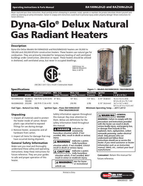
Unpacking1. Unpack all materials used to protect the heater inside of carton. Retain plastic caps attached to exposed fittings for use during storage.2. Remove heater, accessories and all hardware from carton.3. Inspect all items for damage that may have occurred during shipment.General Safety InformationMake sure you read and thoroughly understand these safety and operating instructions. Keep these instructions for future reference. They are your guides to safe and proper operation of this heater.Safety information appears throughout this manual. Pay close attention to them. Below are definitions for the safety information listed throughout this manual.Indicates an im m inen t lyhazardous situation which, if notavoided, WILL result in death or serious injury.Indicates a potentially hazardoussituation which, if not avoided, COULD result in death or serious injury.Indicates a potentially hazardoussitua t ion which, if not avoided, MAY result in minor or moderate injury.Consumer: Retain this manual for future reference.Dyna-Glo ®Delux Natural Gas Radiant HeatersPlease read and save these instructions. Read carefully before attempting to assemble, install, operate or maintain the product described. Protect yourself and others by observing all safety information. Failure to comply with instructions could result in personal injury and/or property damage! Retain instructions for future reference.DescriptionDyna-Glo Delux Models RA100NGDGD and RA250NGDGD heaters are 50,000 to 100,000 and 250,000 BTU/Hr construction heaters. These heaters use natural gas for combustion. They are primarily intended for temporary heating of well-ventilated buildings under construction, alteration or repair. These heaters should be utilized in sheltered, well-ventilated areas, but never in occupied dwellings.Ignitor SizeGapL x W x H (in.)RA100NGDGD 50,000 to 104 ft 3/hr (2.95 m 3/h) 8” W.C. 14” W.C.7.5” W.C. 0.19“ (4.8mm) 16.3 x 16.3 x 29.8 100,000(41.4 x 41.4 x 75.7 cm)RA250NGDGD 250,000 260 ft 3/h (7.36 m 3/h) 10 PSI 250 PSI6 PSI 0.19” (4.8 mm) 14.7 x 14.7 x 44.3 (37.3 x 37.3 x 112.5 cm)Fuel Type – Natural Gas Only Ignition Type – P iezo (RA100NGDGD)Minimum Operating Temp. – -20°F (-29°C)Pilot (RA250NGDGD)SpecificationsGHP Group, Inc.6440 W Howard St Niles, IL 60714ANS Z83.7-2011 CSA 2.14-2011 Construction HeaterC USC USFigure 1 – Models RA100NGDGD / RA250NGDGDGeneral Safety Informationconstruction heater in accordance with ANS Z83.7 CSA 2.14. Other standards govern the use of fuel gases and heating products for specific uses. Your local authority can inform you of these. The primary purpose of these construction heaters are to provide temporaryheating of building under construction, alteration, or repair. When properlyused, the heater provides safe economical heating. Products of combustion are vented into the heated area.- For either indoor or outdoor use. Adequate ventilation must be provided.IMPORTANT: Every possible circum-stance that might involve a hazard can-not be anticipated. The warnings in this manual on tags or decals affixed to the unit are not all inclusive. If a procedure,work method, or operating technique not specifically recommended by Day-ton is used, you must make sure it is safe for you and others. You should also ensure that equipment will not be dam-aged or be made unsafe by the operat-ing or maintenance method you use.death! Some people are more affected by Carbon Monoxide than others. Early signs of carbon monoxide poisoning resemble the flu, with headaches, dizziness, and/or nausea. If you have these signs, theheater may not be operating properly or the area may not be sufficientlyventilated. Get fresh air at once! Have heater serviced.Carefully install and always use great carewhen operating this heater. Be sure to research and follow all local ordinances and codes. In the absence of local codes, with the Standard for the Storage and Handling of Liquefied Petroleum Gases, ANSI/NFPA 58 and the Natural Gas and Propane Installation Code CSA B149.1.Natural Gas: Natural gas has a very distinctive odor that will help you detect a leak. However, this odor may fade in time. Natural gas may be present in the area even though no odor is detected.– U se only natural gas. Do not attempt to use propane gas. Use only factory preset regulator provided on heater.– P rovide adequate ventilation. Before using heater, provide at least a 3square foot (.28 m 2) opening of fresh, outside air for every 100,000 BTU/Hr rating.CaliforniaProposition 65Warning: Fuels used in gas or oil fired appliances and the products of combustion of such fuels, contain chemicals known to the State ofCalifornia to cause cancer, birth defects or other reproductive harm. This product contains chemicals, including lead and lead compounds, known to the state ofCalifornia to cause cancer, birth defects or other reproductive harm. Wash hands after handling.– T his heater should be utilized in sheltered, well-ventilated areas, but never in occupied dwellings.– D o not use heater in occupieddwellings, in living or sleeping areas.– K eep appliance clear and free from combustible materials, gasoline, paint thinner, and other flammable vapors and liquids. Dust is combustible. Do not use heaters in areas with high dust content.– C heck heater for damage before each use. Do not use damaged heater.®Radiant HeatersGeneral Safety Information (Continued)Minimum heater clearance from combustibles:Sides: 6 feet (1.8 m) Top: 5 feet (1.5 m)Floor: Combustible - Not for use on finished floors– T he heater, other than a heater with integral propane gas container, must be located at least 6 feet (1.8 m) (in Canada, distance must be 10 feet [3 m]) from any propane gas container.– B lower or radiant type heaters shall not be directed toward any propane gas container within 20 feet (6 m).– C heck hose before each use of heater. Do not use if hose is cut or damaged. Replace with hose specified by manufacturer.– A lways be sure to place the heater onheater is in operation.– T damage may occur.– P water or rain.– K from the heater.– N – A lways wear gloves when handling the heater to prevent injury.– N ever attach ductwork to heater.– D o not alter heater. Keep heater in its original state.– D o not use heater if altered.– T urn off gas supply to heater whennot in use.– U se only original replacement parts.This heater must use design specific parts. Do not substitute or use generic parts. Improper replacement parts could cause serious or fatal injury.AssemblyMODEL RA100NGDGD1. Provide natural gas supply system.2. Install plumbing to a low pressure natural gas source to heater. The source must be regulated to 1/2 PSI, maximum 3/4’’ (19 mm) I.D. pipe or flexible connector, not longer than 10 feet (3 m).3. Be sure to use thread sealingcompound when connecting the hose to the heater at the 1/2’’ (13 mm) NPT fitting at the regulator inlet. Tighten all fittings with a wrench.4. Open natural gas supply valve Never use an open flame to check for aleak. Apply 50/50 mixture of liquid soap and water to all joints. Bubbles forming show a leak. Correct all leaks at once.6. Close natural gas supply valve.MODEL RA250NGDGD1. Insert AA battery (included) into ignition by turning COUNTERCLOCKWISE and unscrewing ignition cap.2. Provide natural gas supply system.3. Install plumbing to a natural gas source to heater.4. Connect gas supply to heater using minimum 3/8” (10 mm) ID pipe.Maximum pipe length is 10 feet (3 m).5. Connect hose or plumbing to 1/2” (13 mm) NPT flare fitting at thevalve inlet. Tighten all fittings with a wrench.6. Open natural gas supply valveSLOWLY. Check all connections for leaks. Never use an open flame to check for leaks.7. Close natural gas supply valve. NOTE: Keep hands and face away from outlet (around top of shelf) of heater while attempting to start heater.Models RA100NGDGD and RA250NGDGDDyna-Glo Delux Operating Instructions and Parts ManualFigure 3 – Heater Control Knob –RA100NGDGDHot while inoperation. Do nottouch. Keep children, clothing, furniture,gasoline, and other liquids havingflammable vapors away.The gas supply attaches to the heaterby a minimum 3/8’’ (10 mm) I.D. pipeor flexible connector. User must supplypipe or flexible connector. The lengthshould be no more than 10 feet (3 m).The natural gas moves through the2. Always be sure to place the heater ona stable and level surface while theheater is in operation. Be sure that nostrong winds blow into the ends ofthe heater.to OFF position.4. Turn natural gas supply valve on.5. Depress heater control knob andturn counterclockwise to (IGN) LOWTO SHUT DOWN HEATER1. Shut off the main burner valve, beingsure to wear a glove for protection.Turn the control knob to the OFFposition.2. Firmly close the natural gas supplyvalve.TO RESTART HEATER1. Wait five minutes for heater to cool.2. Follow steps in TO START HEATERsection.TO START HEATER (RA250NGDGD)1. Follow all of the safety, ventilationand installation instructionspreviously noted in this manual.2. Always be sure to place the heater ona stable and level surface while theheater is in operation. Be sure that nostrong winds blow into the ends ofthe heater.3. SLOWLY open the gas valve.4. Push in and hold safety valve buttonwhile pushing ignitor button untilpilot lights (see Figure 4).NOTE: Hose may be filled with air, ifso, allow around 15 seconds for gas toreach pilot.5. If pilot does not light, repeat Step 4.6. When pilot stays lit, fully open themain burner valve by turning thehandle of the burner valve counter-clockwise until it stops all the way tothe ON position.®Radiant HeatersFigure 4 – RA250NGDGD Part IdentificationOperation (Continued) NOTE: Arrows on main burner valve handle show directions for ON and OFF.TO SHUT DOWN HEATER1. Firmly close the natural gas supply valve.2. Shut off the main burner valve, being sure to wear a glove for protection.the way to the OFF position.TO RESTART HEATER1. Wait five minutes for heater to cool.2. Follow steps in TO START HEATERsection.Running heaterbelow specified gaspressure may cause flashback. Duringflashback, the burner flame is mostlyyellow. The flame will burn inside theburner tube causing a roaring noise. Ifflashback occurs, turn heater off. Afterburner tube cools off, restart heater.NATURAL GAS SUPPLYYou must provide the natural gas supplyalong with all pipe and fittings.Check with your local gas supplier toproperly size all of your supply lines. Besure to follow all local codes, or refer tothe Natural Fuel Gas Code Handbook –NFPA54/ANSI Z223.1, or the Natural GasInstallation Code – CAN/CSA B149.1.VENTILATIONA three square footopening of freshoutside air for each 100,000 BTU/Hr ofheater output must be provided tooperate each heater safely. If the properventilation air is not provided, carbonmonoxide poisoning can occur.Always be sure that the properventilation is being provided beforestarting this heater.FRESH OUTSIDE AIR OPENINGREQUIREMENTSHeater size Opening100,000 BTU 3.0 ft2 (.28 m2)250,000 BTU 7.5 ft2 (.70 m2)Read and understandall of the warnings inthe General Safety Information pages of thismanual. They are essential to the safeoperation of this heater. Be sure to followall local codes when operating this heater.Be sure to leak test allfittings and pipeconnections after installation or repairs. Usea 50/50 mixture of liquid dish soap andwater. Bubbles forming reveal a leak. Youmust repair all leaks at once!Models RA100NGDGD and RA250NGDGD Dyna-Glo Delux Operating Instructions and Parts ManualFigure 5 – RA100NGDGD Part IdentificationKnobNever attempt toservice heater whileit is connected to natural gas supply,operating, or hot. Severe burns can occur.1. Always keep heater clean.2. Inspect heater before each use.Check connections for leaks. Applya 50/50 solution of dish soap andwater. Bubbles forming show a leakthat must be corrected. Correct leaksat once.3. Inspect regulator hose assemblybefore each use. If hose is highlyworn or cut, replace with hosespecified by manufacturer.4. Keep appliance area clear and freefrom combustible materials, gasoline,and other flammable vapors andliquids.5. Have heater inspected yearly by aqualified service person.6. The flow of combustion andventilation air cannot be obstructed.STORAGEDisconnect heaterfrom natural gassupply.1. Place plastic cover over brass fittingon inlet connector.2. Store in a dry, clean, safe place.3. When taking the heater out ofstorage, always check inside theheater. Small animals or insects mayplace foreign objects in the heater.Keep heater free from foreign objectsand combustible materials.®Radiant HeatersSymptom Possible Cause(s) Corrective ActionBurner fails to lightBurner lights but goes outwhen automatic controlvalve button is releasedBurn rate is low, emitterdoes not glowFlames are extremely highand coming from emitter1. More warm-up time needed2. Gas pressure is low3. Thermocouple loose or in need ofreplacement4. Automatic control valve in need ofreplacement1. Main burner valve not completely open2. Clogged gas orifice3. Low gas pressure4. Low gas supply1. Main burner valve not fully open2. Plugged gas orifices3. Low gas pressure4. Low fuel supplyUnit has been connected to a propane gassupply instead of natural gas1. Relight, holding control valve button in for45 seconds2. Inspect natural gas supply3. Tighten, reconnect or replacethermocouple4. Replace automatic control valve1. Completely open main burner valve byturning control knob to HIGH position2. Replace gas orifice3. Check gas supply, regulator function4. Contact gas supplier1. Fully open main burner valve by turningcontrol knob towards HIGH position until itstops2. Replace gas orifice3. Check gas supply, regulator output4. Consult gas supplierCheck gas source and replace with natural gassupplyTroubleshooting ChartFor Repair Parts, call 1-877-447-4768 Please provide following information:-Model number-Serial number (if any)-Part description and number as shown in parts list ArrayFigure 6 – Repair Parts Illustration for Natural Gas Radiant Heater RA100NGDGDModel RA100NGDGDDyna-Glo Delux Operating Instructions and Parts ManualRepair Parts List for Natural Gas Radiant Heater RA100NGDGD1 Top Cover 5002854 12 Guard 2315528 13 Emitter 2315519 14 N ozzle2315521 1 5 Nozzle Connector 2315545 1 6 Nozzle Nut2315546 1 7 Main Gas Tubing Assy (NG) 2315523 1 8 Nozzle Bracket 2315517 1 9 Flame Shield 2315516 2 10 Thermocouple 2201584 1 11 Spark Plug2201583 1 12 Thermocouple Holder 2315520 1 13 Base5002851 1 14 Control Knob 2101451 1 15 Control Valve GS22 (8B) 1 16 Fitting2304948 2 17 Tubing Inlet Assy2315524 1 18 Fitting-Regulator to Tubing Inlet 2315547 1 19 Regulator2315555 1 20 Regulator Bracket 2315518 1ReferenceNumber DescriptionRA100NGDGDQuantityHeater must use designspecific parts. Do not substitute or use generic parts. Improper replacement parts could cause serious or fatal injuries.Figure 7 – Repair Parts Illustration for Natural Gas Radiant Heater RA250NGDGDFor Repair Parts, call 1-877-447-4768Please provide following information:-Model numberModel RA250NGDGDDyna-Glo Delux Operating Instructions and Parts ManualRepair Parts List for Natural Gas Radiant Heater RA250NGDGD1 Top Cover 5002854 12 Guard 2315554 13 Emitter 2315537 14 Upper Base 5002853 15 Base Cover 2315532 16 Lead Wire 2315643 17 Tilt Switch 2300186 18 Lower Base 5002852 19 Blanket 2315539 1 10 Insulation 2315544 1 11 Flame Shield 2315540 1 12 Thermocouple 2201591 1 13 Spark Plug2201583 1 14 Spark Plug Bracket 2315609 1 15 Bracket2315520 1 16 Box for Lead Wire 2315535 1 17 Pilot Assy GL250.39 1 18 Pilot Bracket 2315608 1 19 Wind Box 2315610 1 20 Ignition Wire 2201585 1 21 Battery 2300481 1 22 Ignition 2201220 1 23 Regulator2315513 1 24 Regulator Holder 2315536 1 25 Regulator Connector 2315547 1 26 Inlet Tubing Assy 2315542 1 27 Connector 2315549 1 28 Control ValveGS16 1 29 Contol Valve Fixing Nut 2305687 1 30 Contol Valve Bracket 2315538 1 31 Ball ValveGQ01 1 32 Ball Valve Connector 2305391 1 33 Pilot Connector 2315548 1 34 Main Tubing Assy 2315550 1 35 Pilot Tubing 2001402 1 36 Base Shield2315541 1 37 Rubber Ring for Wire 2315543 1 38 Nozzle Bracket 2315533 1 39 Nut2101008 1 40 Nozzle Connector 2315534 1 41 Nozzle 2315546 1Reference Number DescriptionRA250NGDGDQuantityHeater must use designspecific parts. Do not substitute or use generic parts. Improper replacement parts could cause serious or fatal injuries.WarrantyRA100NGDGD and RA250NGDGD Dyna-Glo Delux Operating Instructions and Parts ManualLIMITED WARRANTY:This limited warranty is extended to the original retail purchaser of this Forced Air/Convection/Radiant Heater and warrants against anydefect in materials and workmanship for a period of one (1) year from the date of retail sale. GHP Group, Inc., at it’s option, will eitherprovide replacement parts or replace or repair the unit, when properly returned to the retailer where purchased or one of our service centersas directed by GHP Group, Inc., within one (1) year of retail purchase. (Shipping costs, labour costs, etc. are the responsibility of the purchaser.)DUTIES OF THE OWNER:This heating appliance must be operated in accordance with the written instructions furnished with this heater.This warranty shall not excusethe owner from properly maintaining this heater in accordance with the written instructions furnished with this heater.A bill of sale,canceledcheck or payment record must be kept to verify purchase date and establish warranty period.Original carton should be kept in case of warrantyreturn of unit.WHAT IS NOT COVERED:1.Damage resulting from use of improper fuel.2.Damage caused by misuse or use contrary to the owners manual and safety guidelines.3.Damage caused by a lack of normal maintenance.4.Fusese of non-standard parts or accessories.6.Damage caused in transit.Freight charges on warranty parts or heaters to and from the factory shall be the responsibility of the owner.This warranty does not imply or assume any responsibility for consequential damages that may result from the use,misuse,or the lack ofroutine maintenance of this heating appliance.A cleaning fee and the cost of parts may be charged for appliance failures resulting from lack ofmaintenance.This warranty does not cover claims which do not involve defective workmanship or materials.FAILURE TO PERFORMGENERAL MAINTENANCE(INCLUDING CLEANING)WILL VOID THIS WARRANTY.THIS LIMITED WARRANTY IS GIVEN TO THE PURCHASER IN LIEU OF ALL OTHER WARRANTIES,EXPRESSED OR IMPLIED,INCLUDING BUT NOT LIMITED TO THE WARRANTIES OF MERCHANTABILITY OF FITNESS FOR A PARTICULAR PURPOSE.THEREMEDY PROVIDED IN THIS WARRANTY IS EXCLUSIVE AND IS GRANTED IN LIEU OF ALL OTHER REMEDIES.IN NO EVENT WILLGHP GROUP, INC. BE LIABLE FOR INCIDENTAL OR CONSEQUENTIAL DAMAGES.Some states do not allow limitations on how long an implied warranty lasts,so the above limitation may not apply to you.Some states do notallow the exclusion or limitation of incidental or consequential damages so the above limitation or exclusion may not apply to you.CLAIMS HANDLED AS FOLLOWS:1.Contact your retailer and explain the problem.2.If the retailer is unable to resolve the problem,contact ourCustomer Service Dept.detailing the heater model,the problem,and proofof date of purchase.3.A representative will contact you.DO NOT RETURN THE HEATER TO GHP GROUP,INC.unless instructed by our Representative.This warranty gives you specific legal rights and you may also have other rights which vary from state to state.TO REGISTER THE WARRANTY ON YOUR HEATER,PLEASE FILL OUT THIS CARD COMPLETELYAND MAIL WITHIN14DAYS FROM DATE OF PURCHASE OR REGISTER ON-LINE AT NAME:______________________________________PHONE:()__________________EMAIL:____________________________ADDRESS:_________________________________CITY:______________________________STATE:__________ZIP:____________MODEL:____________________SERIAL#:_______________________________________DATE PURCHASED:__________________DEALER PURCHASED FROM:____________________________________________TYPE OF STORE:__________________________CITY&STATE WHERE PURCHASED:______________________________________________PRICE PAID:_______________________Please Take a Minute To Give Us Your Answers To The Following Questions.All Responses Are Used Solely For Market Research And Are Held In Strict Confidence.Who primarily decided this purchase?Male Female18-2425-3940-5960and overPurpose of Purchase?_______________________________________________________________________________________________Do you own any other portable heaters?Yes No If yes,type____________________________brand_____________________How do you intend to use your new heater?Construction Site Farm Warehouse/Commercial Garage/Outbuilding OtherHow did you become aware of this heater?In-Store Display Newspaper Ad Magazine Ad Friend/RelativeTV Commercial Store Salesperson Other___________________________What made you select this heater?Style Size/Portability Price Package Brand Other___________________Do you:own rent Would you recommend this heater to a friend?Yes NoPlease give us your comments:________________________________________________________________________________________THANK YOU FOR COMPLETING THIS FORM!Information will be held confidential.WARRANTY REGISTRATIONIMPORTANT:We urge you to fill out your warranty registration card within fourteen (14)days of date of purchase.You can also register your warranty on the internet atplete the entire serial number.Retain this portion of the card for your records.SAVE THIS CARD!Place Postage Stamp Here Tel: (877) GHP Group, Inc.6440 W Howard St Niles, IL 60714-3302GHP Group, Inc.6440 W Howard StNiles, IL 60714-3302。
海尔FCD-JTHML说明书

FCD-JTHML45/55/65/80/100-III(E) 银海象A5一、型号及解释二、产品外观、内部结构、随机附件产品外观:内部结构:A.热水出口 B冷水进口 C加热管 D搪瓷内胆 E进水管 F出水管 J 控制板 K镁棒随机附件:三、电脑板操作控制面板介绍:1.工作模式选择键(中/保键)2.调节键3.功能键4.开/关键5.夜电选定图案6.预约2选定图案7.功率指示图案8.时钟指示数码9.预约1选定图案 10.中温保温选定图案 11.温度指示条安装好后,首次使用因内胆无水,必须先开启自来水进水阀门,待内胆水满,出水口连续出水后,关闭阀门,检查各接口处有无漏水,插上电源。
1、开机:首次使用时,显示屏仅时钟点亮,时钟显示12:00并开始走时,进入待机状态,按一下“开/关”键,进入上次设定工作状态,相应的指示灯点亮。
2、功率选择:开机状态下,连续按“功能”键进入功率选择状态,按“调节”键可在800W、1200W、2000W三档功率间选择,当选定加热功率为800W时,功率指示图标中的半圆点亮,上层加热管单独启动。
当选定加热功率为1200W时,功率指示图案中的半圆与周围光芒交替点亮,下层加热管单独启动。
当选定2000W时,功率指示图案的半圆及周围光芒共同点亮,上下加热棒同时加热。
下图中,加热功率为2000W,时钟当前时间为12:10,设定最高加热温度为75℃的即时加热模式。
3、温度设置:开机状态下,按“功能”键可进入温度设置状态,温度值指示条快速闪烁,按“调节”键调整到要设定的温度(温度数值在35-75℃内以5℃进行变化),此时可继续按“功能”键进入时钟设置或不操作6秒后机器自动确认并退出设置。
注:在非设置状态时,显示屏动画交替显示实际水温与设置温度。
当温度灯从35℃向右移动时表示正在显示实际温度,在到达实际水温后一起熄灭。
当温度灯从75℃向左移动时表示正在显示设置温度,在到达设定温度后一起熄灭。
设定温度与实际温度交替显示。
海尔家用电器产品说明书

Series 8, Built-in oven, 60 x 60 cm, Stainless steelHBG672BS1BIncluded accessories2 x combination grid, 1 x universal panOptional accessoriesHEZ324000 Inlaid wire shelf for multipurpose pan, HEZ327000 Pizza stone, HEZ617000 Pizza pan, enamelled, HEZ625071 Grill tray, anthracite enamelled, HEZ631070 Baking tray, enamelled,HEZ632070 Multipurpose pan, enamelled, HEZ633001 Lid for professional pan, enamelled, HEZ633070 Professional pan, enamelled, HEZ634000 Baking and roasting grid (standard),HEZ636000 Glass pan, HEZ638170 1 level telescopic rail, full ext, pyro, HEZ638270 2 level telescopic rails, full ext,pyro, HEZ638370 3 level telescopic rails, full ext,pyro, HEZ660050 Cover Strip,HEZ6BCA0 Cookbook, HEZ864000 Glass tray, HEZ9020 Conversion cabinet, HEZ9041 Conversion cabinet, HEZ915001 Glass roasting dish, 5,1 L The built-in oven: you get perfect baking and roasting results.• 4D Hotair: even heat distribution for perfect results – on any level.• TFT display control: easy-to-use thanks to the control ring with full text and symbols.• Pyrolytic self-cleaning: Automatically cleans the oven, just wipe out the ash.• Drop down door with SoftOpen and SoftClose: the oven door opens and closes gently and quietly• Fast pre heatingTechnical DataInstallation type: ......................................................................Built-in Integrated Cleaning system: ..................................................Pyrolytic Min. required niche size for installation (HxWxD): 585-595 x 560-568 x 550 mmDimensions: ........................................................595 x 595 x 548 mm Dimensions of the packed product (HxWxD): .....670 x 680 x 670 mm Control Panel Material: ................................................Stainless steel Door Material: ............................................................................Glass Net weight: ..............................................................................37.7 kg Usable volume of cavity: ...............................................................71 l Cooking method: .....4D Hotair, Defrost, Full width grill, Hot Air-Eco, Conventional heat, Conventional heat ECO, Pizza setting, Hot air grillingOven control: ......................................................................electronic Number of interior lights: .. (1)Length of electrical supply cord: ..........................................120.0 cm EAN code: (4242002881539)Number of cavities (2010/30/EC): (1)Energy efficiency rating: ..................................................................A+ Energy consumption per cycle conventional (2010/30/EC): ........0.87 kWh/cycleEnergy consumption per cycle forced air convection (2010/30/EC):0.69 kWh/cycleEnergy efficiency index (2010/30/EC): .....................................81.2 % Connection rating: ..................................................................3600 W Fuse protection: ...........................................................................16 A Voltage: ...............................................................................220-240 V Frequency: ...........................................................................50; 60 Hz Plug type: .....................no plug (electrical connection by electrician) Included accessories: .............2 x combination grid, 1 x universal panSeries 8, Built-in oven, 60 x 60 cm, Stainless steelHBG672BS1BThe built-in oven: you get perfect baking and roasting results.Key Information- 2.5“-TFT colour and text display with direct select buttons- Drop down door, SoftClose, SoftOpen- Digital temperature display with proposal- Actual temperature display Heating-up indicator- Automatic programmes- Pyrolytic self-cleaning function- Pyrolytic proof baking trayDesign- Bosch control wheel- Straight bar handleFeatures- Electronic clock timer- Main on/off switch- 1 interior light- Interior halogen light, Light on/off when oven door opened/closed - Light on/off when oven door opened/closed- Control panel lock- Automatic safety switch off Residual heat indicator Start button Door contact switch- Cavity inner surface: enamel anthracite- Removable wire shelf support rails- 5 shelf positions- Full glass inner door- Info buttonProgrammes/functions- Oven with 8 cooking functions:, 8 cooking functions: heating methods: 4D Hotair, Hotair Gentle, conventional top and bottom heat, conventional heat Gentle, Hotair grilling, full width variable grill, pizza function, defrost- Fast pre-heating functionPerformance/technical information- Temperature range 30 °C - 275 °C- Cavity volume: 71 litre capacity- Integral cooling fan- Stainless-steel fan- 120 cm Cable length- Total connected load electric: 3.6 KW- Appliance dimension (hxwxd): 595 mm x 595 mm x 548 mm- Niche dimension (hxwxd): 585 mm - 595 mm x 560 mm - 568 mm x 550 mm- Please refer to the dimensions provided in the installation manual - Maximum window temperature 30° C- Energy efficiency rating (acc. EU Nr. 65/2014): A+- Energy consumption per cycle in conventional mode:81.2- Energy consumption per cycle in fan-forced convection mode:0.69 kwh - Number of cavities: 1 Cavity volume:71 litre capacity Standard accessories- Available as an additional accessory- 2 x combination grid, 1 x universal panSeries 8, Built-in oven, 60 x 60 cm,Stainless steel HBG672BS1B。
海尔冷柜说明书

HRE/HFE-127B-_HD使用说明书是本产品不可分割的重要组成部分,用户须妥善保管。
请务必仔细阅读本使用说明书中描述的指南和警告事项,因为这些指南和警告事项中文I. 一般信息 (1)1.1...................................................................................................... )D H C -B 741-E R H (构结 ............. ..... 2. 附件...................................................................................................................................................1 3. 安装位置.. (1)4.2................................................................................................................................................... 装安 5. 层板和导轨 . (3)3...................................................................................................................... )准标(托板层和板层]a [3.................................................................................................................................... )制定(轨导 4................................................................................................................................. )制定(杆撑支 6. 电气连接.. (4)7.4........................................................................................................................................接连管水排 II. 操作说明 (5)1. 启动 ................................................................................................................................................5 2. 前板 ...................................................................................................................................................5 3. 柜内温度设置 (6)4. 框架加热器 ........................................................................................................................................6 5. 除霜 (6)6. 关机 ...................................................................................................................................................7 III. 保养和清洁说明 .. (7)1. 内部、外部、层板 .............................................................................................................................7 2. 空气过滤网 ........................................................................................................................................7 IV. 报修前 .. (8)1. 显示故障代码的故障 (8)2. 不显示故障代码的故障 .....................................................................................................................8 V. 废弃处理.................................................................................................................................................8 VII. 气候类型说明 (9)ENGLISHI. INSTALLATION INSTRUCTIONS (10)1. CONSTRUCTION (HRE-147B-SHD) .........................................................................................10 2. ACCESSORIES ..........................................................................................................................10 3. LOCATION .................................................................................................................................10 4. SET UP .......................................................................................................................................11 5. SHELF AND RAIL .......................................................................................................................12 21.................................................................................... )d r a d n a t s ( P I L C F L E H S D N A F L E H S ]a [ [b] RAIL (customized) .................................................................................................................12 [c] HANGER (customized) ..........................................................................................................13 6. ELECTRICAL CONNECTIONS .................................................................................................13 7. DRAIN CONNECTIONS .............................................................................................................13 II. OPERATING INSTRUCTIONS ........................................................................................................14 1. START UP ..................................................................................................................................14 2. FRONT PANEL ...........................................................................................................................15 3. CABINET TEMPERATURE SETTING .......................................................................................15 4. FRAME HEATER ........................................................................................................................16 5. DEFROST ...................................................................................................................................16 6. SHUT DOWN ..............................................................................................................................16 III. MAINTENANCE ...............................................................................................................................16 1. INTERIOR, EXTERIOR, SHELF .................................................................................................16 2. AIR FILTER ................................................................................................................................17 IV. BEFORE CALLING A SERVICE AGENT .........................................................................................17 1. TROUBLES WITH ERROR CODE INDICATION .......................................................................17 2. TROUBLES WITHOUT ERROR CODE INDICATION ...............................................................18 V. DISPOSAL .......................................................................................................................................18 VI. WARRANTY . (18)[b][c]VI. 保修 (9)警告请勿弄湿本产品或在潮湿环境下使用本产品。
- 1、下载文档前请自行甄别文档内容的完整性,平台不提供额外的编辑、内容补充、找答案等附加服务。
- 2、"仅部分预览"的文档,不可在线预览部分如存在完整性等问题,可反馈申请退款(可完整预览的文档不适用该条件!)。
- 3、如文档侵犯您的权益,请联系客服反馈,我们会尽快为您处理(人工客服工作时间:9:00-18:30)。
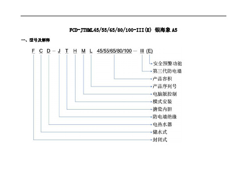
FCD-JTHML45/55/65/80/100-III(E) 银海象A5一、型号及解释
二、产品外观、内部结构、随机附件
产品外观:
内部结构:
A.热水出口 B冷水进口 C加热管 D搪瓷内胆 E进水管 F出水管 J 控制板 K镁棒
随机附件:
三、电脑板操作
控制面板介绍:
1.工作模式选择键(中/保键)
2.调节键
3.功能键
4.开/关键
5.夜电选定图案
6.预约2选定图案
7.功率指示图案
8.时钟指示数码
9.预约1选定图案 10.中温保温选
定图案 11.温度指示条
安装好后,首次使用因内胆无水,必须先开启自来水进水阀门,待内胆水满,出水口连续出水后,关闭阀门,检查各接口处有无漏水,插上电源。
1、开机:
首次使用时,显示屏仅时钟点亮,时钟显示12:00并开始走时,进入待机状态,按一下“开/关”键,进入上次设定工作状态,相应的指示灯点亮。
2、功率选择:
开机状态下,连续按“功能”键进入功率选择状态,按“调节”键可在800W、1200W、2000W三档功率间选择,当选定加热功率为800W时,功率指示图标中的半圆点亮,上层加热管单独启动。
当选定加热功率为1200W时,功率指示图案中的半圆与周围光芒交替点亮,下层加热管单独启动。
当选定2000W时,功率指示图案的半圆及周围光芒共同点亮,上下加热棒同时加热。
下图中,加热功率为2000W,时钟当前时间为12:10,设定最高加热温度为75℃的即时加热模式。
3、温度设置:
开机状态下,按“功能”键可进入温度设置状态,温度值指示条快速闪烁,按“调节”键调整到要设定的温度(温度数值在35-75℃内以5℃进行变化),此时可继续按“功能”键进入时钟设置或不操作6秒后机器自动确认并退出设置。
注:在非设置状态时,显示屏动画交替显示实际水温与设置温度。
当温度灯从35℃向右移动时表示正在显示实际温度,在到达实际水温后一起熄灭。
当温度灯从75℃向左移动时表示正在显示设置温度,在到达设定温度后一起熄灭。
设定温度与实际温度交替显示。
当35℃至实际水温灯动画显示时,表示热水器处于加热状态,当一起点亮时表示处于保温状态。
4、校准时钟:
时钟以24小时制、60分钟,秒闪显示并走时。
例:校准时钟为11:29。
在开机状态下,连续按“功能”键并进入时钟校准状态,时钟小时闪烁,按“调节”键将数值调整到11,再按“功能”键,时钟分钟数码闪烁,按“调节”键调整到29,此时可继续按功能键进行预约设置,或不操作6秒后,系统自动确认并退出设置。
5、中温保温设置:
在开机状态下,连续按“中/保”键,可进入中温保温工作模式。
机器自动在35℃-40℃间选择最节能的保温温度,水温下降至35℃时。
机器自动重新开始加热。
注:默认最高加热温度为40℃不可调,适用于少量用水需求,不适合淋浴。
6、预约时间设置:
可设置两档用水时间,设置时间以电脑板时间为基准。
在预约模式下,系统默认加热功率为2000W不可调。
例:设置预约1用水时间为10:00。
开机状态下,连续按“功能”键进入预约1设置状态,预约1选定图案闪烁,同时时钟数码闪烁,按“调节”键调到10:00,此时可按功能键确认当前设置并进入预约2设置时间,不操作约6秒,机器自动确认并退出设置。
预约2设置方法与预约1设置方法相同。
注:若在预约前大量使用热水,导致热水器到达预约时间未能达到设定温度,机器将自动延时加热半小时并停止。
若电压太低,功率达不到2000W 导致热水器到达预约时间仍未能达到设定温度,机器也将自动延时半小时并停止。
7、夜电设置:
开机状态下,连续按“中/保”键,可进入夜电工作模式。
加热时间为00:00-06:00,加热功率与最高加热温度可人工设置调节。
8、运行模式选择:
开机状态下,每按“中/保”键一次,系统将在中温保温、夜电、预约1、预约2、预约1+预约2和即时加热/保温中选择。
9、关机:
当淋浴完后,如想进行关机可按“开/关”键。
四、技术参数
型号
容量
(L)额定电源额定功率(W)
额定压
力(Mpa)
额定温
度(℃)
防水
等级
净重
(kg)
a1(mm)b1(mm)c1(mm)d1(mm)
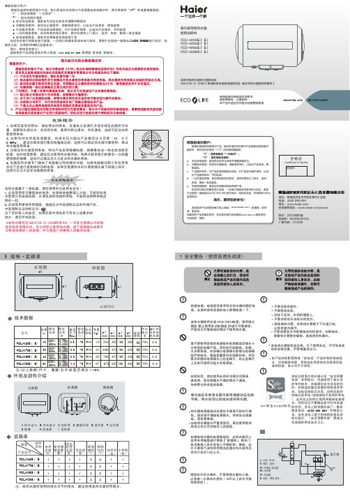
FCD-JTHML45-II (E)45220V~/50Hz800/1200/20000.7575IPX420667444100410 FCD-JTHML55-II (E)55220V~/50Hz800/1200/20000.7575IPX422.8752444100410
注:以上参数(温度、功率值除外)允许误差范围为±10%。
