给个锐捷三层交换机dhcp配置实例和思科模拟器上的dhcp配置实例
思科三层交换机配置实例及命令
思科三层交换机配置实例及命令思科三层交换机配置实例及命令交换机的命名一般是WS开头这个是固定的,再下一个字母有两种一个是C一个是X,C代表固化交换机或者机箱,X代表的是模块。
下面是店铺精心整理的思科三层交换机配置实例及命令,仅供参考,希望能够帮助到大家。
三层交换机是不是经常让你机器不好使,看看下面的三层交换机配置文章,一切问题都能解决。
本文详细介绍实例讲解:全面的三层交换机配置比较全面的三层交换机配置实例,带命令解释哟!三层交换机配置:Enable //进入私有模式Configure terminal //进入全局模式service password-encryption //对密码进行加密hostname Catalyst 3550-12T1 //给三层交换机定义名称enable password 123456. //enable密码Enable secret 654321 //enable的加密密码(应该是乱码而不是654321这样)Ip subnet-zero //允许使用全0子网(默认都是打开的)Ip name-server 172.16.8.1 172.16.8.2 //三层交换机名字Catalyst 3550-12T1对应的IP地址是172.16.8.1Service dhcp //提供DHCP服务ip routing //启用三层交换机上的路由模块Exit三层交换机配置:Vtp mode server //定义VTP工作模式为sever模式Vtp domain centervtp //定义VTP域的名称为centervtpVlan 2 name vlan2 //定义vlan并给vlan取名(如果不取名的话,vlan2的名字应该是vlan002)Vlan 3 name vlan3Vlan 4 name vlan4Vlan 5 name vlan5Vlan 6 name vlan6Vlan 7 name vlan7Vlan 8 name vlan8Vlan 9 name vlan9Exit三层交换机配置:interface Port-channel 1 //进入虚拟的以太通道组1switchport trunk encapsulation dot1q //给这个接口的trunk封装为802.1Q的帧格式switchport mode trunk //定义这个接口的工作模式为trunkswitchport trunk allowed vlan all //在这个trunk上允许所有的vlan通过Interface gigabitethernet 0/1 //进入模块0上的吉比特以太口1 switchport trunk encapsulation dotlq //给这个接口的trunk封装为802.1Q的帧格式switchport mode trunk //定义这个接口的工作模式为trunkswitchport trunk allowed vlan all //在这个trunk上允许所有的vlan通过channel-group 1 mode on //把这个接口放到快速以太通道组1中Interface gigabitethernet 0/2 //同上switchport trunk encapsulation dotlqswitchport mode trunkswitchport trunk allowed vlan allchannel-group 1 mode on三层交换机配置:port-channel load-balance src-dst-ip //定义快速以太通道组的负载均衡方式(依*源和目的IP的方式)interface gigabitethernet 0/3 //进入模块0上的.吉比特以太口3switchport trunk encapsulation dotlq //给trunk封装为802.1Qswitchport mode trunk //定义这个接口的工作模式为trunkswitchport trunk allowed vlan all //允许所有vlan信息通过interface gigabitethernet 0/4 //同上switchport trunk encapsulation dotlqswitchport mode trunkswitchport trunk allowed vlan allinterface gigbitethernet 0/5 //同上switchport trunk encapsulation dotlqswitchport mode trunkswitchport trunk allowed vlan allinterface gigbitethernet 0/6 //同上switchport trunk encapsulation dotlqswitchport mode trunkswitchprot trunk allowed vlan all三层交换机配置:interface gigbitethernet 0/7 //进入模块0上的吉比特以太口7 Switchport mode access //定义这个接口的工作模式为访问模式switchport access vlan 9 //定义这个接口可以访问哪个vlan(实际就是分配这个接口到vlan)no shutdownspanning-tree vlan 6-9 cost 1000 //在生成树中,vlan6-9的开销定义为10000interface range gigabitethernet 0/8 – 10 //进入模块0上的吉比特以太口8,9,10switchport mode access //定义这些接口的工作模式为访问模式switchport access vlan 8 //把这些接口都分配到vlan8中no shutdown三层交换机配置:spanning-tree portfast //在这些接口上使用portfast(使用portfast以后,在生成树的时候不参加运算,直接成为转发状态) interface gigabitethernet 0/11 //进入模块0上的吉比特以太口11switchport trunk encapsulation dotlq //给这个接口封装为802.1Qswitchport mode trunk //定义这个接口的工作模式为trunkswitchport trunk allowed vlan all //允许所有vlan信息通过interface gigabitethernet 0/12 //同上switchport trunk encapsulation dotlqswitchport mode trunkswitchport trunk allowed vlan allinterface vlan 1 //进入vlan1的逻辑接口(不是物理接口,用来给vlan做路由用)ip address 172.16.1.7 255.255.255.0 //配置IP地址和子网掩码no shutdown三层交换机配置:standby 1 ip 172.16.1.9 //开启了冗余热备份(HSRP),冗余热备份组1,虚拟路由器的IP地址为172.16.1.9standby 1 priority 110 preempt //定义这个三层交换机在冗余热备份组1中的优先级为110,preempt是用来开启抢占模式interface vlan 2 //同上ip address 172.16.2.252 255.255.255.0no shutdownstandby 2 ip 172.16.2.254standby 2 priority 110 preemptip access-group 101 in //在入方向上使用扩展的访问控制列表101interface vlan 3 //同上ip address 172.16.3.252 255.255.255.0 no shutdown三层交换机配置:standby 3 ip 172.16.3.254standby 3 priority 110 preemptip access-group 101 ininterface vlan 4 //同上ip address 172.16.4.252 255.255.255.0 no shutdownstandby 4 ip 172.16.4.254standby 4 priority 110 preemptip access-group 101 ininterface vlan 5ip address 172.16.5.252 255.255.255.0 no shutdownstandby 5 ip 172.16.5.254standby 5 priority 110 preemptip access-group 101 ininterface vlan 6ip address 172.16.6.252 255.255.255.0 no shutdown三层交换机配置:standby 6 ip 172.16.6.254standby 6 priority 100 preempt interface vlan 7ip address 172.16.7.252 255.255.255.0 no shutdownstandby 7 ip 172.16.7.254standby 7 priority 100 preemptinterface vlan 8ip address 172.16.8.252 255.255.255.0no shutdownstandby 8 ip 172.16.8.254standby 8 priority 100 preemptinterface vlan 9ip address 172.16.9.252 255.255.255.0no shutdown三层交换机配置:standby 9 ip 172.16.9.254standby 9 priority 100 preemptaccess-list 101 deny ip any 172.16.7.0 0.0.0.255 //扩展的访问控制列表101access-list 101 permit ip any anyInterface vlan 1 //进入vlan1这个逻辑接口Ip helper-address 172.16.8.1 //可以转发广播(helper-address 的作用就是把广播转化为单播,然后发向172.16.8.1)Interface vlan 2Ip helper-address 172.16.8.1Interface vlan 3ip helper-address 172.16.8.1interface vlan 4ip helper-address 172.16.8.1interface vlan 5ip helper-address 172.16.8.1interface vlan 6ip helper-address 172.16.8.1interface vlan 7ip helper-address 172.16.8.1interface vlan 9ip helper-address 172.16.8.1router rip//启用路由协议RIPversion 2//使用的是RIPv2,如果没有这句,则是使用RIPv1network 172.16.0.0//宣告直连的网段exit三层交换机配置:ip route 0.0.0.0 0.0.0.0 172.16.9.250//缺省路由,所有在路由表中没有办法匹配的数据包,都发向下一跳地址为172.16.9.250这个路由器line con 0line aux 0line vty 0 15//telnet线路(路由器只有5个,是0-4)password 12345678//login密码loginendcopy running-config startup-config 保存配置。
在思科交换机上配置dhcp实例
在思科交换机上配置dhcp实例解决方案:一,如果不用交换机的DHCP功能而是利用PC的DHCP功能!1.在交换机上配置DHCP服务器: ip dhcp-server 192.168.0.692.在交换机中为每个VLAN设置同样的DHCP服务器的IP地址: interface Vlan11 ip address 192.168.1.254 255.255.255.0 ip helper-address 192.168.0.69 DHCP Server IP interface Vlan12 ip address 192.168.2.254 255.255.255.0 ip helper-address 192.168.0.69 DHCP Server IP3.在DHCP服务器上设置网络地址分别为192.168.1.0、192.168.2.0的作用域,并将这些作用域的“路由器”选项设置为对应VLAN的接口IP地址。
二利用三层交换机自带的DHCP功能实现多VLAN的IP地址自动分配(一) 配置方法一1.同时为多个VLAN的客户机分配地址2.VLAN内有部分地址采用手工分配的方式3.为客户指定网关、Wins服务器等4.VLAN 2的地址租用有效期限为1天,其它为3天5.按MAC地址为特定用户分配指定的IP地址最终配置如下:ip dhcp excluded-address 10.1.1.1 10.1.1.19 //不用于动态地址分配的地址ip dhcp excluded-address 10.1.1.240 10.1.1.254ip dhcp excluded-address 10.1.2.1 10.1.2.19!ip dhcp pool global //global是pool name,由用户指定network 10.1.0.0 255.255.0.0 //动态分配的地址段domain-name //为客户机配置域后缀dns-server 10.1.1.1 10.1.1.2 //为客户机配置dns服务器netbios-name-server 10.1.1.5 10.1.1.6 //为客户机配置wins服务器netbios-node-type h-node //为客户机配置节点模式(影响名称解释的顺利,如h-node=先通过wins服务器解释...)lease 3 //地址租用期限: 3天ip dhcp pool vlan1network 10.1.1.0 255.255.255.0 //本pool是global的子pool, 将从global pool继承domain-name等optiondefault-router 10.1.1.100 10.1.1.101 //为客户机配置默认网关!ip dhcp pool vlan2 //为另一VLAN配置的poolnetwork 10.1.2.0 255.255.255.0default-router 10.1.2.100 10.1.2.101lease 1!ip dhcp pool vlan1_john //总是为MAC地址为...的机器分配...地址host 10.1.1.21 255.255.255.0client-identifier 010050.bade.6384 //client-identifier=01加上客户机网卡地址!ip dhcp pool vlan1_tomhost 10.1.1.50 255.255.255.0client-identifier 010010.3ab1.eac8相关的DHCP调试命令:no service dhcp //停止DHCP服务[默认为启用DHCP服务]sh ip dhcp binding //显示地址分配情况show ip dhcp conflict //显示地址冲突情况debug ip dhcp server {events | packets | linkage} //观察DHCP服务器工作情况如果DHCP客户机分配不到IP地址,常见的原因有两个。
cisco三层交换机配置vlan和DHCP攻略
cisco三层交换机配置vlan和DHCP攻略ip dhcp pool IT_WEIXIU //配置DHCP服务network 10.42.86.0 255.255.255.224 //配置DHCP网段default-router 10.42.86.30 //DHCP分配网关(应为vlan接口IP)dns-server 10.42.0.82 10.1.2.9 10.1.2.70 //DHCP分配DNSnetbios-name-server 10.1.2.9 10.1.2.70 10.1.2.222 //DHCP分配WINS!vlan 100 //建立vlanname IT_weixiu //vlan命名interface FastEthernet0/25switchport access vlan 100!interface FastEthernet0/26switchport access vlan 100!interface FastEthernet0/27switchport access vlan 100!interface FastEthernet0/28switchport access vlan 100!interface FastEthernet0/29switchport access vlan 100!interface FastEthernet0/30switchport access vlan 100 //端口指定vlan!!interface Vlan100 //配置vlan接口description IT_weixiuip address 10.42.86.30 255.255.255.224 //配置vlan接口IP为网关no ip proxy-arpip ospf 100 area 42 //加入ospf动态路由图(因下方已包含,本条不必要)!interface Vlan200description To_SongZiip address 10.42.85.30 255.255.255.224ip helper-address 10.42.0.16 //指定本网段DHCP服务器为分公司(不指定本条即由本网段内提供DHCP服务或不提供)no ip proxy-arpip ospf 100 area 42 ┗━DHCP服务采用广播协议,故:1不能跨网段;2同一网段只能一台DHCP服务! “ip helper-address”命令即专用来解决DHCP不能跨网段问题。
实验1:三层交换机配置和DHCP中继
实验1:三层交换机配置和DHCP中继
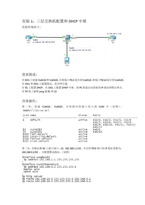
实验环境如下:
需求描述:
在SW1上创建VLAN10和VLAN20,并将端口F0/1划分到VLAN10,将端口F0/14划分到VLAN20。
在SW1和SW2上配置路由,是全网互通。
在R1上配置DHCP,在SW1上配置DHCP中继,使PC机能自动获取到IP地址和默认网关。
在PC机上能够ping通R1和L0.
具体操作:
第一步:创建VLAN10,VLAN20。
并将相应的端口加入到VLAN中(如图)。
第二步:在路由器R2上建立端口:L0:192.168.1.1/32。
并且将F0/0端口的IP地址设置为:192.168.0.2/30 ,并配置静态路由。
(如图)
第三步:将SW1上的VLAN10与VLAN20配上相应的IP(pc与R1的网关地址),如:VLAN10 IP:192.168.10.254/24,VLAN20 IP:192.168.20.254/24.还有F0/15的IP:192.168.0.1/30。
然后再配置一条默认路由指向R2,并在SW1上开启路由功能。
最后在VLAN10的接口模式下键入:IP help-address 192.168.20.1 (如图)
第四部:将R1上的F0/0接口配置IP地址:192.168.20.1/24.并创建DHCP地址池:192.168.10.0/24并配置相关参数。
最后写一条默认路由指向SW1。
(如图)
第五步:验证PC是否得到相应的IP地址并进行全网PING通。
到此本实验全部完成!!!。
如何在三层交换机配置DHCP
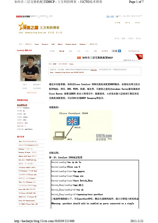
51CTO首页我的博客搜索社区:论坛博客下载读书更多登录注册首页|微软活动|Cisco |Security |VoIP |Office |Windows Server |Windows 7|IT职业生涯51cto 51cto博客之星博客之星 用户名:hackerjx 文章数:61 评论数:489 访问量:232011 无忧币:2031 博客积分:3371 博客等级:7注册日期:2008-05-18[Win 7]原来的桌面属性那.. 追梦五年-我和51CTO的那些事 Windows 7 中的“亮.. Windows XP Mode,发布应.. Office 2010 Beta 简体中.. 802.1X认证+DHCP+ACS Ser.. 配置在一台三层交换上,.. 揭秘Cisco NBAR封杀BT和.. 解密Windows 7中的XP Mode 企业网络中部署Cisco ACS.. 配置多台三层交换VLAN间.. [Win 7]安装Windows 7好.. 大中型企业中部署应用AAA.. Cisco SSL VPN 配置详解 配置Cisco IOS EASY VPN ..ISCW实验3:配置Cisco PP.. Cisco IP Communicator .. 使用SDM配置Cisco Easy VPN博客博客统计统计统计信息信息热门热门文章文章hackerjx 的BLOG写留言邀请进圈子发消息加友情链接进家园 加好友MSN/QQ 论坛 开心 人人 豆瓣 新浪微博 分享到:博主的更多文章>>标签:DHCP 多层交换配置 Cisco原创作品,允许转载,转载时请务必以超链接形式标明文章 原始出处 、作者信息和本声明。
否则将追究法律责任。
/383839/215400通过本实验实验掌握掌握掌握,,如何在如何在Cisco Catalyst Cisco Catalyst Cisco Catalyst 3550 3550 3550交交换机来配置配置DHCP DHCP DHCP服服务,实现对实现对内内网主机分配IP IP地址地址地址,,网关,DNS DNS,,WINS WINS,,租期租期,,域名等域名等。
鸿鹄论坛_思科锐捷三层交换机配置DHCP

需求:vlan 10中的PC能自动获取到192.168.10.0网段,vlan 20中的PC能自动获取到192.168.20.0的网段。
预配:Switch>enSwitch#conf tEnter configuration commands, one per line. End with CNTL/Z.Switch(config)#no ip domain loSwitch(config)#lin con 0Switch(config-line)#exeSwitch(config-line)#exec-timeout 0 0Switch(config-line)#loggSwitch(config-line)#logging sSwitch(config-line)#logging synchronous第一步:在三层交换机上配置VLAN并配IP地址作为网关Switch(config)#vlan 10Switch(config-vlan)#name banggongSwitch(config-vlan)#exitSwitch(config)#vlan 20Switch(config-vlan)#name shengchangSwitch(config-vlan)#exitSwitch(config)#intvlan 10Switch(config-if)#ip add 192.168.10.1 255.255.255.0Switch(config-if)#no shSwitch(config-if)#exitSwitch(config)#intvlan 20Switch(config-if)#ip add 192.168.20.1 255.255.255.0Switch(config-if)#no sh第二步:在三层交换机上配置DHCP服务Switch(config)#ipdhcp excluded-address 192.168.10.1Switch(config)#ipdhcp excluded-address 192.168.20.1排除作为网关的地址Switch(config)#ipdhcp pool vlan10Switch(dhcp-config)#network 192.168.10.0 255.255.255.0Switch(dhcp-config)#default-router 192.168.10.1有DNS服务器的话还要填写DNS服务器的地址Switch(dhcp-config)#dns-serverx.x.x.xSwitch(dhcp-config)#exitSwitch(config)#ipdhcp pool vlan20Switch(dhcp-config)#network 192.168.20.0 255.255.255.0Switch(dhcp-config)#default-router 192.168.20.1第三步:在二层交换机上创建VLAN 10和VLAN 20Switch(config)#vlan 10Switch(config-vlan)#exitSwitch(config)#vlan 20Switch(config-vlan)#exitSwitch(config)#int range f0/2 - 4Switch(config-if-range)#switchport mode accessSwitch(config-if-range)#switchport access vlan 10Switch(config-if-range)#exitSwitch(config)#int range f0/5 - 7Switch(config-if-range)#switchport mode accessSwitch(config-if-range)#switchport access vlan 20锐捷系列与思科配置完全一样,但是要注意配置前一定要开启DHCP服务service dhcp上次在配置的时候忘了配置这条命令,结果怎么也获取不到IP。
锐捷三层交换机DHCP配置实例和思科模拟器上的DHCP配置
S3760(dhcp-config)# network 192.168.3.0 255.255.255.0
S3760(dhcp-config)# dns-server 202.101.115.55
S3760 (config)#ip dhcp ping packets 1 ----在dhcp server分配IP时会先去检测将要分配的IP地址是否已有人使用,如果没人使用则分配,若已有人使用则再分配下一个IP
S3760 (config)#ip dhcp excluded-address 192.168.2.1 192.168.2.10
步骤一:配置VLAN网关IP地址,及将相关端口划入相应的VLAN中
S3760#con t
S3760(config)#vlan 2 ----创建VLAN2
S3760(config-vlan)#exit ----退回到全局配置模式下
S3760 (dhcp-config)# lease infinite ----租期时间设置为永久
S3760 (dhcp-config)# network 192.168.2.0 255.255.255.0 ----给客户端分配的地址段
S3760 (dhcp-config)# dns-server 202.101.115.55 ----给客户端分配的DNS
S3760(config)#vlan 3 ----创建VLAN3
S3760(config-vlan)#exit ----退回到全局配置模式下
S3760(config)#int vlan 2 ----进入配置VLAN2
[原创]Cisco三层交换机与Routeros OSPF+DHCP服务器配置实例
![[原创]Cisco三层交换机与Routeros OSPF+DHCP服务器配置实例](https://img.taocdn.com/s3/m/21bf0b42a8956bec0975e343.png)
[原创]Cisco三层交换机与Routeros OSPF+DHCP服务器配置实例本案例使用Cisco三层交换机结合Mikrotik Routeros配置OSPF动态路由及多Vlan Dhcp服务器中继配置。
使用设备如下三层交换机:Cisco 3550 EMI接入层交换机:HUAWEI Quidway S2008Mikrotik RouterOs 3.13网络拓扑如下:配置目的:验证Routeros OSPF动态路由及DHCP中继配置文档:CISCO 3550ip routing#开启路由功能#ip dhcp excluded-address 10.100.0.100#设置dhcp服务器ip地址#interface FastEthernet0/2switchport trunk encapsulation dot1qswitchport mode trunk#设置与2层交换机互联的trunk端口#interface FastEthernet0/23switchport access vlan 2switchport mode accessspanning-tree portfast#设置与ros连接的端口的vlan#interface Vlan2description serverip address 10.100.0.1 255.255.255.0#设置3层交换机vlan接口ip#!interface Vlan3description officeip address 10.100.3.1 255.255.255.0ip helper-address 10.100.0.100!#设置3层交换机vlan接口ip及配置dhcp中继# interface Vlan4description salesip address 10.100.4.1 255.255.255.0ip helper-address 10.100.0.100!#设置3层交换机vlan接口ip及配置dhcp中继# interface Vlan5description usersip address 10.100.5.1 255.255.255.0ip helper-address 10.100.0.100!#设置3层交换机vlan接口ip及配置dhcp中继# router ospf 10router-id 10.100.0.1log-adjacency-changesnetwork 10.100.0.0 0.0.255.255 area 10.100.0.0 #配置ospf进程及area信息#HUAWEI Quidway S2008 配置:interface Ethernet0/6switchport access vlan 5!#配置用户端口#interface Ethernet0/7switchport access vlan 3!#配置用户端口#interface Ethernet0/8switchport access vlan 4#配置用户端口#interface Ethernet0/9switchport mode trunkswitchport trunk allowed vlan all!#设置与3层交换机互联的trunk端口#Mikrotik Routeros:/ip pooladd name="vlan3" ranges=10.100.3.2-10.100.3.254add name="vlan4" ranges=10.100.4.2-10.100.4.254add name="vlan5" ranges=10.100.5.2-10.100.5.254#设置不同Vlan的地址池#/ip dhcp-serveradd address-pool=vlan3 authoritative=after-2sec-delay bootp-support=static \ disabled=no interface=in lease-time=3d name="vlan3" relay=10.100.3.1 add address-pool=vlan4 authoritative=after-2sec-delay bootp-support=static \ disabled=no interface=in lease-time=3d name="vlan4" relay=10.100.4.1 add address-pool=vlan5 authoritative=after-2sec-delay bootp-support=static \ disabled=no interface=in lease-time=3d name="vlan5" relay=10.100.5.1#设置Dhcp-server 使之支持Dhcp中继#/routing ospf areaadd area-id=0.0.0.0 authentication=none disabled=no name="backbone" \ type=defaultadd area-id=10.100.0.0 authentication=none disabled=no name="area1" \ type=default#配置ospf area#/ip addressadd address=10.100.0.100/24 broadcast=10.100.0.255 comment="" disabled=no \interface=in network=10.100.0.0#配置内部IP地址#/ip dnsset allow-remote-requests=yes cache-max-ttl=1w cache-size=2048KiB \ max-udp-packet-size=512 primary-dns=192.168.100.208 \#配置dns#/ip firewall natadd action=masquerade chain=srcnat comment="" disabled=no \ src-address=10.100.0.0/16#配置NAT#/routing ospfset distribute-default=always-as-type-2 metric-bgp=20 metric-connected=20 \ metric-default=1 metric-rip=20 metric-static=20 mpls-te-area=unspecified \ mpls-te-router-id=unspecified redistribute-bgp=no \redistribute-connected=no redistribute-rip=no redistribute-static=no \router-id=10.100.100.2/routing ospf interfaceadd authentication=none authentication-key="" cost=10 dead-interval=40s \ disabled=no hello-interval=10s interface=in network-type=broadcast \passive=no priority=1 retransmit-interval=5s transmit-delay=1s/routing ospf networkadd area=area1 disabled=no network=10.100.0.0/16#配置OSPF路由协议#。
DHCP服务配置(锐捷三层)
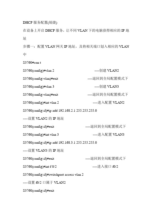
DHCP服务配置(锐捷)在设备上开启DHCP服务,让不同VLAN下的电脑获得相应的IP地址步骤一:配置VLAN网关IP地址,及将相关端口划入相应的VLAN 中S3760#con tS3760(config)#vlan 2 ----创建VLAN2S3760(config-vlan)#exit ----退回到全局配置模式下S3760(config)#vlan 3 ----创建VLAN3S3760(config-vlan)#exit ----退回到全局配置模式下S3760(config)#int vlan 2 ----进入配置VLAN2 S3760(config-if)#ip add 192.168.2.1 255.255.255.0----设置VLAN2的IP地址S3760(config-if)#exit ----退回到全局配置模式下S3760(config)#int vlan 3 ----进入配置VLAN3 S3760(config-if)#ip add 192.168.3.1 255.255.255.0----设置VLAN3的IP地址S3760(config-if)#exit ----退回到全局配置模式下S3760(config)#int f 0/2 ----进入接口f0/2S3760(config-if)#switchport access vlan 2----设置f0/2口属于VLAN2S3760(config-if)#exitS3760(config)#int f 0/3 ----进入接口f0/3S3760(config-if)#switchport access vlan 3 ----设置f0/3口属于VLAN3S3760(config-if)#exit步骤二:配置DHCP serverS3760 (config)#service dhcp ----开启dhcp server功能S3760 (config)#ip dhcp ping packets 1----在dhcp server分配IP时会先去检测将要分配的IP地址是否已有人使用,如果没人使用则分配,若已有人使用则再分配下一个IPS3760 (config)#ip dhcp excluded-address 192.168.2.1 192.168.2.10----设置排斥地址为192.168.2.1至192.168.2.10的ip地址不分配给客户端(可选配置)S3760 (config)#ip dhcp excluded-address 192.168.3.1 192.168.3.10----设置排斥地址为192.168.3.1至192.168.3.10的ip地址不分配给客户端(可选配置)S3760 (config)#ip dhcp pool test2 ----新建一个dhcp地址池名为test2S3760 (dhcp-config)# lease infinite ----租期时间设置为永久S3760 (dhcp-config)# network 192.168.2.0 255.255.255.0S3760 (dhcp-config)# dns-server 202.101.115.55 ----给客户端分配的DNSS3760(dhcp-config)# default-router 192.168.2.1 ----客户端的网关S3760(dhcp-config)#exitS3760(config)#ip dhcp pool test3 ----新建一个dhcp地址池名为test3S3760(dhcp-config)# lease infinite ----租期时间设置为永久S3760(dhcp-config)# network 192.168.3.0 255.255.255.0S3760(dhcp-config)# dns-server 202.101.115.55S3760(dhcp-config)# default-router 192.168.3.1S3760(dhcp-config)#end。
三层交换机配置多VLAN和DHCP服务器实例

三层交换机配置多VLAN和DHCP服务器实例因为公司的网络升级需要划分VLAN,多VLAN下所有的客户端要使用DHCP来自动分配I P地址。
其实DHCP服务器我们使用多的是Windows的DHCP,Linux下的DHCP服务。
但是3 550本身也是可以担当DHCP服务器的。
经过简单配置测试通过。
详细配置过程作为日后参考。
VLAN划分及地址分配:一台3550EMI交换机,划分7个vlan10、vlan20、vlan30、vlan40、vlan50、vlan60、vlan2。
vlan2为服务器所在网络,vlan10、vlan20、vlan30、vlan40、vlan50、vlan60为客户机所在vlan,IP地址段和vlan的对应关系如下:vlan2、 192.168.251.0 255.255.255.0 网关 192.168.251.1vlan10、192.168.10.0 255.255.255.0 网关 192.168.10.1vlan20、192.168.20.0 255.255.255.0 网关 192.168.20.254vlan30、192.168.30.0 255.255.255.0 网关 192.168.30.254vlan40、192.168.40.0 255.255.255.0 网关 192.168.40.254vlan50、192.168.50.0 255.255.255.0 网关 192.168.50.254vlan60、192.168.60.0 255.255.255.0 网关 192.168.60.254/*注意:这里在规划的时候各vlan的网关IP就是将来划分vlan是个vlan的接口IP 地址*/。
端口1-4默认划到VLAN1(保留备用),端口5-6划分到VLAN60,端口7-8划分到VLAN 50,端口9-10划分到VLAN40,端口11-12划分到VLAN30,端口13-14划分到VLAN20,端口1 5-16划分到VLAN10,端口17-24划分到VLAN2。
三层交换机做dhcp实验实例.doc
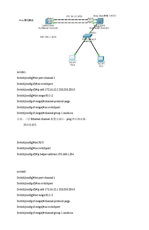
switch1:Switch(config)#int port-channel 1Switch(config-if)#no switchportSwitch(config-if)#ip add 172.16.12.2 255.255.255.0Switch(config)#int range f0/1-2Switch(config-if-range)#channel-protocol pagpSwitch(config-if-range)#no switchportSwitch(config-if-range)#channel group 1 mode on注意:三层Ethernet channel配置完成后,ping两台路由器,测试连通性Switch(config)#int f0/3Switch(config)#no switchportSwitch(config-if)#ip helper-address 192.168.1.254switch0:Switch(config)#int port-channel 1Switch(config-if)#no switchportSwitch(config-if)#ip add 172.16.12.1 255.255.255.0Switch(config)#int range f0/1-2Switch(config-if-range)#channel-protocol pagpSwitch(config-if-range)#no switchportSwitch(config-if-range)#channel group 1 mode onSWitch(config)#ip dhcp pool ccnaSwitch(config-dhcp)#network 192.168.1.0 255.255.255.0Switch(config-dhcp)#default-router 192.168.1.254Switch(config-dhcp)#ip dhcp excluded-add 192.168.1.254注意:(1)当Windows 客户端无法从DHCP 服务器租约到IP 地址时,计算机会自动产生一个169.254.0.0/16 的IP地址。
CISCO三层交换机怎么配置DHCP服务
CISCO三层交换机怎么配置DHCP服务交换机的主要功能包括物理编址、网络拓扑结构、错误校验、帧序列以及流控。
交换机还具备了一些新的功能,如对VLAN(虚拟局域网)的支持、对链路汇聚的支持,甚至有的还具有防火墙的功能。
对于多VLAN的IP地址自动分配,我们可以利用dhcp服务实现,那么在三层交换机上如何配置DHCP服务呢,下面一起来看看方法步骤1、首先将三层交换机开机,电脑telnet 远程连接,并进入全局模式下2、在全局模式下开启DHCP服务,输入“service dhcp”,然后按回车3、指定不通过DHCP 地址池中分配的地址,也就是排除的地址。
这里排除192.168.1.1到192.168.1.10的地址,输入“ip dhcp excluded-address 192.168.1.1 192.168.1.10"4、配置一个名为“cs”的地址池,输入”ip dhcp pool cs"5、指定要通过DHCP分配的网段和掩码,输入”netw ork 192.168.1.0 255.255.255.0"6、为客户机配置DNS服务器,输入“dns-server 218.2.135.1"7、设置地址租用期为”3“,输入”lease 3",租期可以根据实际情况做调整8、为客户机配置网关为“192.168.1.1”,输入“default-router 192.168.1.1”9、这样就设置完成了,只要是属于192.168.1.0/24网段的客户机就可以自动获取IP地址了。
这里注意了,如果存在多个VLAN,每个VLAN都需要设置DHCP服务。
补充:交换机基本使用方法作为基本核心交换机使用,连接多个有线设备使用:网络结构如下图,基本连接参考上面的【方法/步骤1:基本连接方式】作为网络隔离使用:对于一些功能好的交换机,可以通过模式选择开关选择网络隔离模式,实现网络隔离的作用,可以只允许普通端口和UPlink端口通讯,普通端口之间是相互隔离不可以通讯的除了作为核心交换机(中心交换机)使用,还可以作为扩展交换机(接入交换机)来扩展网络放在路由器上方,扩展网络供应商的网络线路(用于一条线路多个IP的网络),连接之后不同的路由器用不同的IP连接至公网相关阅读:交换机硬件故障常见问题电源故障:由于外部供电不稳定,或者电源线路老化或者雷击等原因导致电源损坏或者风扇停止,从而不能正常工作。
三层交换机配置DHCP
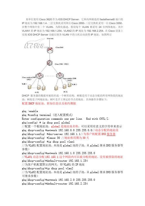
某单位使用Cisco 3620作为IOS DHCP Server,它和内网相连的fastethernet0端口的IP地址为192.168.1.4,二层交换机采用两台Cisco 2950,三层交换机采用一台Cisco 3550。
在整个网络中有二个VLAN,为简化描述,假设每个VLAN都采用24位网络地址,其中VLAN1的IP地址为192.168.1.254,VLAN2的IP地址为192.168.2.254。
在Cisco设备上实现IOS DHCP Server功能以使各VLAN中的主机自动获得IP地址,如图所示DHCP服务器的数据库被组织成一个树形结构,树根是用于动态分配的所有网络段的地址池,树枝是子网地址池,树叶是手工绑定给节点的地址。
具体操作步骤如下:配置DHCP地址池、附加信息以及租约期限ghq >enableghq #config terminal (进入配置模式)Enter configuration commands one per line. End with CNTL/Z.ghq(config) # ip dhcp pool global//配置一个根地址池,global是地址池名称,可以采用有意义的字符串来表示ghq dhcp-config #network 192.168.0.0 255.255.0.0//动态分配的地址段ghq(dhcp-config) #dns-server 192.168.1.1//为客户机配置DNS服务器ghq(dhcp-config) #lease 30 //地址租用期为30天ghq(dhcp-config) #ip dhcp pool vlan1//为VLAN1配置地址池,本池是global池的子池,从global继承DNS服务器等参数)ghq(dhcp-config)#network 192.168.1.0 255.255.255.0//VLAN1动态分配192.168.1这个网段内可以被分配的地址,没有被排除的地址ghq(dhcp-config)#default-router 192.168.1.254//为客户机配置默认的网关,即VLAN1的IP地址ghq(dhcp-config)#ip dhcp pool vlan2//为VLAN2配置地址池,本池是global池的子池,从global继承DNS服务器等可继承参数)ghq(dhcp-config)#network 192.168.2.0 255.255.255.0ghq(dhcp-config)#default-router 192.168.2.254设置不能用于动态分配的IP地址在整个网络中,有些IP地址需要静态的指定给一些特定的设备,例如路由器的端口、DNS服务器、以及VLAN的地址等。
在三层交换机配置DHCP的方法
在三层交换机配置DHCP的方法交换机的主要功能包括物理编址、网络拓扑结构、错误校验、帧序列以及流控。
交换机还具备了一些新的功能,如对VLAN(虚拟局域网)的支持、对链路会聚的支持,甚至有的还具有防火墙的功能。
通过本实验掌握,如何在Cisco Catalyst 3550交换机来配置DHCP效劳,实现对内网主机分配IP地址,网关,DNS,WINS,租期,域名等。
第一步:Catalyst 3550底层配置Switch(config)#no ip do loSwitch(config)#line con 0Switch(config-line)#no exec-tSwitch(config-line)#logg synSwitch(config-line)#host SwitchDhcpSwitchDhcp(config)#int f0/1SwitchDhcp(config-if)#no shSwitchDhcp(config-if)#spanning-tree portfast//连接终端的接口下,开启portfast特性,跳过生成树的选举,接口立即进入转发状态%Warning: portfast should only be enabled on ports connected to a singlehost. Connecting hubs, concentrators, switches, bridges, etc... to thisinterface when portfast is enabled, can cause temporary bridging loops.Use with CAUTION%Portfast has been configured on FastEther0/1 but will onlyhave effect when the interface is in a non-trunking mode.SwitchDhcp(config-if)#end第二步: 开启DHCP效劳,定义分配地址池范围及掩码,网关,DNS,域名,租期等//全局下开启DHCP效劳,该效劳默认是关闭的SwitchDhcp(config)#service dhcp//关闭DHCP分配冲突,日志记录消息SwitchDhcp(config)#no ip dhcp conflict logging//创立DHCP地址池,名称为可以是任意字符SwitchDhcp(config)#ip dhcp pool cisco//指定要通过DHCP分配的网段和掩码,还有另外一种写法(192.168.0.0 255.255.255.0)SwitchDhcp(dhcp-config)#work 192.168.0.0 /24//指定分配的网关地址SwitchDhcp(dhcp-config)#default-router 192.168.0.1//指定DHCP域名,域名可以为任意字符SwitchDhcp(dhcp-config)#domain-name .cisco..//指定PC通过DHCP分配到DNS地址,(这里指定的是当地电信部门的真实地址,全国各地市不一样的)SwitchDhcp(dhcp-config)#dns 218.30.19.40 61.134.1.4//bios效劳器地址,可选的配置SwitchDhcp(dhcp-config)#bios-name-server 192.168.0.10//指定通过DHCP分配到地址,租期为永久SwitchDhcp(dhcp-config)#lease infiniteSwitchDhcp(dhcp-config)#end//指定不通过DHCP 地址池中分配的地址,也就是排除的地址。
实验11 三层交换机和dhcp
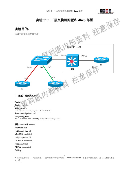
1Router(config)#host sw1 sw1(config)#end*Mar 1 00:09:20.039: %SYS-5-CONFIG_I: Configured from console by consolen添加vlan10和vlan20 sw1#vlan data sw1(vlan)#vlan 10 VLAN 10 modified: sw1(vlan)#vlan 20 VLAN 20 modified: sw1(vlan)#exit APPL Y completed. Exiting....sw1#sh vlan-sVLAN Name Status Ports ---- -------------------------------- --------- ------------------------------- 1 default active110201003 tr 101003 1500 1005 0 - - srb 1 10021004 fdnet 101004 1500 - - 1 ibm - 0 01005 trnet 101005 1500 - - 1 ibm - 0 0sw1#封装trunk链路sw1#conf t*Marsw1(config)#sw1# conf tEnter configuration commands, one per line. End with CNTL/Z.sw1(config)#int f0/0sw1(config-if)#sw mo accsw1(config-if)#sw acc vlan 10sw1(config-if)#int f0/1sw1(config-if)#sw mo accsw1(config-if)#sw acc vlan 20sw1(config-if)#exitsw1(config)#2.配置三层交换机sw2Switch>enSwitch#conf tEnter configuration commands, one per line. End with CNTL/Z. Switch(config)#vlan 103Switch(config-vlan)#exitSwitch(config-vlan)#vlan 20Switch(config-vlan)#exitSwitch(config)#^ZSwitch#Switch#sh vlanVLAN Name1 defaultSwitch(config-if)#end开启路由功能,配置SVI端口,在vlan上部署ip地址Switch(config)#int vlan 10Switch(config-if)#ip add 192.168.10.1 255.255.255.0Switch(config-if)#no shSwitch(config-if)#exitSwitch(config)#int vlan 20Switch(config-if)#ip add 192.168.20.1 255.255.255.0Switch(config-if)#exitSwitch(config)#^ZSwitch#sh ip rout00:09:54: %SYS-5-CONFIG_I: Configured from console by consoleip rouSwitch(config-if)#no shSwitch(config-if)#endSwitch#sw2#sh ip routeCodes: C - connected, S - static, R - RIP, M - mobile, B - BGPD - EIGRP, EX - EIGRP external, O - OSPF, IA - OSPF inter areaN1 - OSPF NSSA external type 1, N2 - OSPF NSSA external type 2E1 - OSPF external type 1, E2 - OSPF external type 2i - IS-IS, su - IS-IS summary, L1 - IS-IS level-1, L2 - IS-IS level-2ia - IS-IS inter area, * - candidate default, U - per-user static routeo - ODR, P - periodic downloaded static routeGateway of last resort is not setC 192.168.10.0/24 is directly connected, Vlan10C 192.168.20.0/24 is directly connected, Vlan2010.0.0.0/24 is subnetted, 1 subnets5C 10.1.1.0 is directly connected, FastEthernet0/11sw2#3.配置R1R2测试路由器Router>Router>enRouter#conf tr1(config)#int e0/0r1(config-if)#no shr1(config-if)#endr1#*Mar 1 00:15:55.551: %SYS-5-CONFIG_I: Configured from console by consoleping*Mar 1 00:15:56.711: %LINK-3-UPDOWN: Interface Ethernet0/0, changed state to up*Marr1#ping 192.168.10.1Type escape sequence to abort.r2(config-if)#ip add 192.168.20.2 255.255.255.0r2(config-if)#no shr2(config-if)#end测试直连邻居r2#ping 192.168.20.1Type escape sequence to abort.Sending 5, 100-byte ICMP Echos to 192.168.20.1, timeout is 2 seconds: .!!!!Success rate is 80 percent (4/5), round-trip min/avg/max = 72/84/96 ms r2#Type escape sequence to abort.Sending 5, 100-byte ICMP Echos to 10.1.1.1, timeout is 2 seconds:.!!!!Success rate is 80 percent (4/5), round-trip min/avg/max = 68/71/72 ms5.部署动态路由协议三层交换机上配置Switch(config)#router eigrp 10Switch(config-router)#net 192.168.10.0Switch(config-router)#net 192.168.20.0Switch(config-router)#net 10.0.0.0Switch(config-router)#end路由器上配置7Router#conf tEnter configuration commands, one per line. End with CNTL/Z. Router(config)#host r3r3(config)#int loop0*Mar 1 00:27:59.703: %LINEPROTO-5-UPDOWN: Line protocol on Interface Loopback0, changed state to upr3(config-if)#ip add 200.1.1.1 255.255.255.0r3(config-if)#exit*Marr3(config-router)#endr3#*Marr3#6.测试路由从R1穿过二层交换机sw1,三层交换机sw2,以及路由器r1#ping 200.1.1.1Type escape sequence to abort.D 200.1.1.0/24 [90/156160] via 10.1.1.2, 00:01:47, FastEthernet0/11 C 192.168.10.0/24 is directly connected, Vlan10C 192.168.20.0/24 is directly connected, Vlan2010.0.0.0/8 is variably subnetted, 2 subnets, 2 masksC 10.1.1.0/24 is directly connected, FastEthernet0/11D 10.0.0.0/8 is a summary, 00:02:58, Null0sw2#r3#sh ip routeCodes: C - connected, S - static, R - RIP, M - mobile, B - BGPD - EIGRP, EX - EIGRP external, O - OSPF, IA - OSPF inter areaN1 - OSPF NSSA external type 1, N2 - OSPF NSSA external type 2E1 - OSPF external type 1, E2 - OSPF external type 2i - IS-IS, su - IS-IS summary, L1 - IS-IS level-1, L2 - IS-IS level-2ia - IS-IS inter area, * - candidate default, U - per-user static routeo - ODR, P - periodic downloaded static routeGateway of last resort is not setC 200.1.1.0/24 is directly connected, Loopback0DCdns-server DNS serversdomain-name Domain nameexit Exit from DHCP pool configuration mode hardware-address Client hardware addresshost Client IP address and masklease Address lease timenetbios-name-servernetbios-node-typenetworknext-servernooptionSwitch(config)#Switch(dhcp-config)#network 192.168.20.0 /24Switch(dhcp-config)#defau 192.168.20.1Switch(dhcp-config)#exitSwitch(config)#ip dhcp exclu 192.168.20.1 192.168.20.10 Switch(config)#Switch#sh ip dhcp ser stMemory usage 5215Address pools 2Database agents 0Automatic bindings 0Manual bindings 0Expired bindings 0Malformed messages 09Message ReceivedBOOTREQUEST 0DHCPDISCOVER 0DHCPREQUEST 0DHCPDECLINEDHCPRELEASEDHCPINFORMMessageBOOTREPL YDHCPOFFERDHCPACKDHCPNAKSwitch#IP address Hardware address Lease expiration…………………….(略)Switch#把路由器R1R2上配置成自动获取地址,查询是否成功。
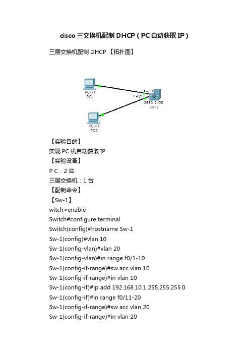
cisco三交换机配制DHCP(PC自动获取IP)
Sw-1(config-if)#ex
Sw-1(config)#ip dhcp pool 10
Sw-1(dhcp-config)#network 192.168.10.0 255.255.255.0 Sw-1(dhcp-config)#default-router 192.168.10.1
三层交换机配制dhcp【拓扑图】【实验目的】实现pc机自动获取ip【实验设备】pc
cisco三交换机配制DHCP(PC自动获取IP)
三层交换机配制DHCP 【拓扑图】
【实验目的】
实现PC机自动获取IP
【实验设备】
P C:2台
三层交换机:1台
【配制命令】
【Sw-1】Hale Waihona Puke witch>enable
Switch#configure terminal
Sw-1(dhcp-config)#dns-server 202.100.192.68
Sw-1(dhcp-config)#do show ru
ip dhcp pool 10
network 192.168.10.0 255.255.255.0
default-router 192.168.10.1
dns-server 221.11.132.2
ip dhcp pool 20
network 192.168.20.0 255.255.255.0 default-router 192.168.20.1
dns-server 202.100.192.680
【测试图】
Sw-1(config-if)#ip add 192.168.10.1 255.255.255.0
- 1、下载文档前请自行甄别文档内容的完整性,平台不提供额外的编辑、内容补充、找答案等附加服务。
- 2、"仅部分预览"的文档,不可在线预览部分如存在完整性等问题,可反馈申请退款(可完整预览的文档不适用该条件!)。
- 3、如文档侵犯您的权益,请联系客服反馈,我们会尽快为您处理(人工客服工作时间:9:00-18:30)。
如对您有帮助,请购买打赏,谢谢您!
如何在设备上开启DHCP服务,让不同VLAN下的电脑获得相应的IP地址?
步骤一:配置VLAN网关IP地址,及将相关端口划入相应的VLAN中
S3760#con t
S3760(config)#vlan 2 ----创建VLAN2
S3760(config-vlan)#exit ----退回到全局配置模式下
S3760(config)#vlan 3 ----创建VLAN3
S3760(config-vlan)#exit ----退回到全局配置模式下
S3760(config)#int vlan 2 ----进入配置VLAN2
S3760(config-if)#ip add ----设置VLAN2的IP地址
S3760(config-if)#exit ----退回到全局配置模式下
S3760(config)#int vlan 3 ----进入配置VLAN3
S3760(config-if)#ip add ----设置VLAN3的IP地址
S3760(config-if)#exit ----退回到全局配置模式下
S3760(config)#int f 0/2 ----进入接口f0/2
S3760(config-if)#switchport vlan 2 ----设置f0/2口属于VLAN2
S3760(config-if)#exit
S3760(config)#int f 0/3 ----进入接口f0/3
S3760(config-if)#switchport vlan 3 ----设置f0/3口属于VLAN3
S3760(config-if)#exit
步骤二:配置DHCP server
S3760 (config)#service dhcp ----开启dhcp server功能
S3760 (config)#ip dhcp ping packets 1 ----在dhcp server分配IP时会先去检测将要分配的IP地址是否已有人使用,如果没人使用则分配,若已有人使用则下一个IP
S3760 (config)#ip dhcp excluded-address
----设置排斥地址为
S3760 (config)#ip dhcp excluded-address
----设置排斥地址为
S3760 (config)#ip dhcp pool test2 ----新建一个dhcp名为test2
S3760 (dhcp-config)# lease ----租期时间设置为永久
S3760 (dhcp-config)# network ----给客户端分配的地址段
S3760 (dhcp-config)# dns-server ----给客户端分配的DNS
S3760(dhcp-config)# default-router ----客户端的网关
S3760(dhcp-config)#exit
S3760(config)#ip dhcp pool test3 ----新建一个dhcp名为test3
S3760(dhcp-config)# lease ----租期时间设置为永久
S3760(dhcp-config)# network
S3760(dhcp-config)# dns-server
S3760(dhcp-config)# default-router
S3760(dhcp-config)#end
S3760#wr。