台湾晶元5050lmw5050w-3规格书18-20lm
5050参数
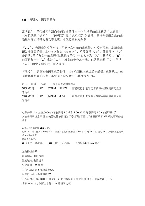
mcd、流明瓦、照度的解释流明瓦”:单位时间光源向空间发出的使人产生光感觉的能量称为“光通量”,其单位就是“流明”。
“流明瓦”是“流明/瓦”的读法,是指光源所发出的光通量与它所消耗的电功率之比,即光源的发光效率。
“mcd”:光通量的空间密度,即单位立体角的光通量,叫发光强度,是衡量光源发光强弱的量,其中文名称为“坎德拉”,符号就是“cd”。
前面那个“m”是词头,是千分之一的意思(就像长度单位,中文名称为“米”,其符号为“m”,前面再加一个“m”成为“mm”,就变成千分之一米,也就是毫米了),所以“mcd”的中文读法为“毫坎德拉”。
“照度”:是指被光源照亮的物体,其单位面积上通过的光通量,通俗地说,就是物体被照亮的程度。
单位是“勒克斯”,其符号为“Lx电压流明功率防水否以及封装类型5050 60灯12V 828LM 14.4W 有滴胶防水,套管防水及防水级别更高的全套管防水3528 60灯12V 240LM 4.8W 有滴胶防水,套管防水及防水级别更高的全套管防水电源参数:12V直流,5050的灯条要用1.5或者2.0A.3528灯条要用1.0A 的就可以了.安装条件和注意事项:安装前物体表面清洁干净,干燥,平整. 灯条背面贴了3M粘胶即可直接粘贴.A类工艺超低光衰LED白光。
此款LED白灯自从2009年2月5日开始老化以来,截至2009年05月28日止,超过2000小时的光衰记录是0%以内光衰。
详细情况如下:1000小时:-4%光衰,2000小时:-1%光衰,外形尺寸:50*50mm贴片光电特性参数:电流越大,电压越高,温度越高,电流越小,发光角度:125度等,正向电流最大不能超过60mA,反向电压最大不能超过5V,工作温度在-35~+60℃之间最好.如果不考虑光衰寿命问题,也可在+85度以下工作,功率:0.18W(与市面上号称0.2W的相同功率),最大承受脉冲电流:250mA, 焊接温度:260±5℃。
5050(GRBW)规格书白光(中文)
Rev.: A
Prepared date: 2015-11-6
Prepared by: calvin chai
Page: 5 of 6
Technical Data Sheet 5050 Top View LEDs
■ 使用说明
1. 过电流保护 客户必须使用电阻来保护,否则电压的漂移会引起电流的大幅度改变 (发生击穿现象). 灯珠使用时电流必须在规定范围之内,避免电流过大造成不良。
Rev.: A
Prepared date: 2015-11-6
发光颜色 红光 绿光 蓝光 白光
表面胶体颜色 白色透明 黄色胶体
Prepared by: calvin chai
Page: 2 of 6
Technical Data Sheet 5050 Top View LEDs
■ 封装尺寸
1. 所有标注尺寸的单位均为毫米 2. 除了特别注明,所有标注尺寸的公差均为±0.10mm
Engineer
Client affirm
Design by 工程部
Date 2015-11-30
深圳市威能照明有限公司
地址: 深圳市宝安区沙井镇新和大道丽城工业园 A 栋 邮编(Postal Code):518000 电话(TEL):0755-27336178 传真(FAX):0755-27336179
█ 绝对最大额定值(Ta = 25℃)
参数
符号
正向电流
IF
峰值正向电流(Duty 1/10 @1KHz)
IFP
功耗
Pd
操作温度
Topr
保存温度
Tstg
回流焊最高温度
Tsol
反向电压
VR
5050参数
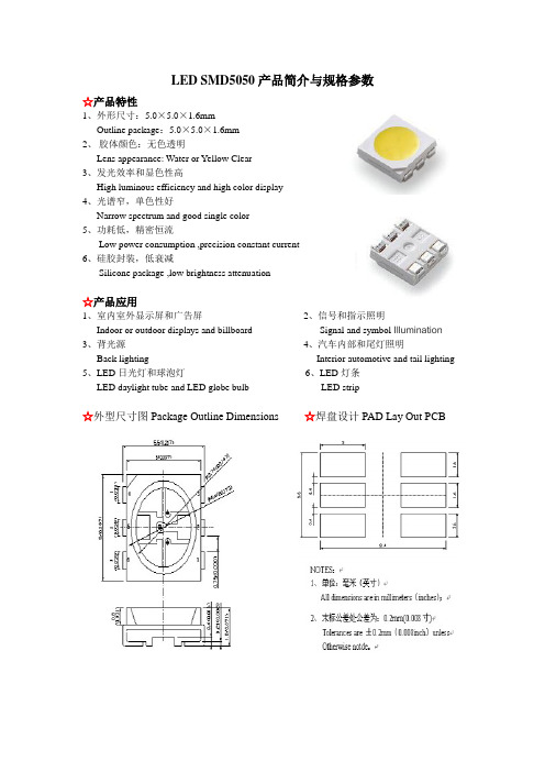
LED SMD5050产品简介与规格参数☆产品特性1、外形尺寸:5.0×5.0×1.6mmOutline package:5.0×5.0×1.6mm2、胶体颜色:无色透明Lens appearance: Water or Yellow Clear3、发光效率和显色性高High luminous efficiency and high color display4、光谱窄,单色性好Narrow spectrum and good single color5、功耗低,精密恒流Low power consumption ,precision constant current6、硅胶封装,低衰减Silicone package ,low brightness attenuation☆产品应用1、室内室外显示屏和广告屏2、信号和指示照明Indoor or outdoor displays and billboard Signal and symbol Illumination 3、背光源4、汽车内部和尾灯照明Back lighting Interior automotive and tail lighting 5、LED日光灯和球泡灯6、LED灯条LED daylight tube and LED globe bulb LED strip☆外型尺寸图Package Outline Dimensions☆焊盘设计PAD Lay Out PCBLED SMD5050 0.2W正白最大绝对额定值Absolute maximum ratings at Ta=25度参数 Parameter 符号Symbol 值Value 单位Unit 功率耗损Power dissipation Pd 200 mW正向电流Forward current If 70 mA反向电压Reverse voltage Vr 5 V 工作温度范围Operating temperature range Topr ﹣40-﹢80 ℃贮存温度范围Storage temperature range Tstg ﹣40-﹢85 ℃最大脉冲电流Peak pulsing current Ifp 100 mA 抗静电能力Electrostatic Discharge ESD 4000 VLED SMD5050 0.2W正白光电特性Electrical optical characteristics at Ta=25度参数Parameter符号Symbol值Value单位Unit测试条件Test Conditions Min Typ Max正向电压Forward voltage VF 3.0 / 3.6 V IF=60 mA 发光强度Luminous intensity IV 3000 4500 Mcd IF=60 mA 角度Viewing angles2θ1/2 120 Dge IF=60 mA 色温Color temperature TC 5500 6500 K IF=60 mA 光通量Luminous flux/ 10 12 Lm IF=60 mA 反向电流Reverse current IR 10 μA VR=5VLED SMD5050 0.2W其他产品光电参数发光颜色Emitting Color 产品型号Model正向电压ForwardVoltage(v)正向电流ForwardCurrent(mA)色温或波段CCT(k) orWD(nm)发光强度LuminousIntensity(Mcd)角度Beanangel(°)蓝色(Blue)SY-5050-BE02 3.0—3.660 460-465600-1800 120 绿色(Green)SY-5050-GN02 3.0—3.660 520-5251800-3000 120 红色(Red )SY-5050-RD02 1.8—2.4 60 620-625800-1500 120 黄色(Yellow)SY-5050-YW02 1.8—2.4 60 585-590600-1500 120RGB SY-5050-RGB021.8—2.4 60 620-625(R)300-500 120 3.0—3.6 60 520-525(G)600-1200 120 3.0—3.6 60 460-465(B)250-600 120温馨提示:所有参数均为实验得出的统计参数,因测试设备、具体使用芯片不同,具体参数以单个产品实验数据为准。
5050三色RGBLED规格书
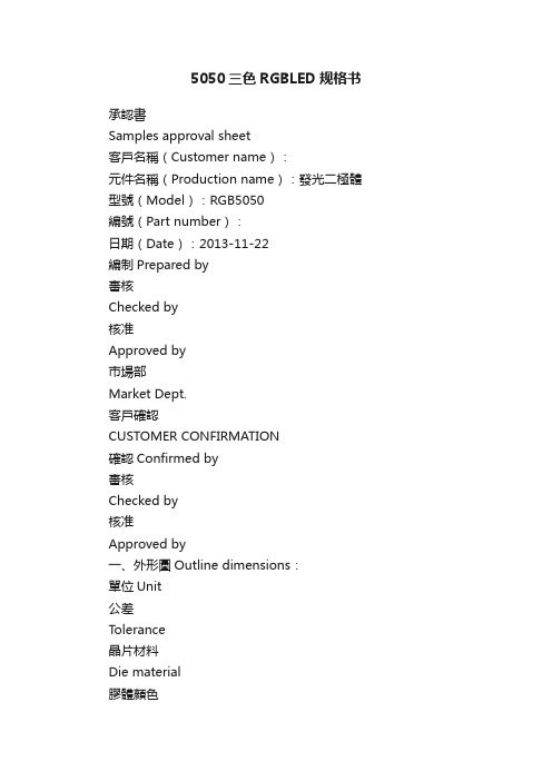
5050三色RGBLED规格书承認書Samples approval sheet客戶名稱(Customer name):元件名稱(Production name):發光二極體型號(Model):RGB5050編號(Part number):日期(Date):2013-11-22編制Prepared by審核Checked by核准Approved by市場部Market Dept.客戶確認CUSTOMER CONFIRMATION確認Confirmed by審核Checked by核准Approved by一、外形圖Outline dimensions:單位Unit公差Tolerance晶片材料Die material膠體顏色Lens color發光顏色Emission colormm ±0.2mm ---- --※備註:承認書之編號和型號可用于查詢,客戶如有需要,請提供相應的編號和型號。
Remark:P/N & Model in samples approval sheet can be used to inquire,please provide corresponding P/N& model if customer need .二、光電參數Photoelectricity Parameter(環境溫度Ambient temperature:25℃濕度humidity:RH60%)項目Item符號Symbol測試條件Testcondition最小值Min典型值Type最大值Max單位Unit正向電壓Forward voltage VF IF=20mA R 1.9 -- 2.1V IF=20mA G 3.0 -- 3.3IF=20mA B 3.0 -- 3.3反向電流Reverse current IR VR=5V -- -- 10 μA發光強度Luminous intensity IV IF=20mA R 700 -- 900MCD IF=20mA G 1500 -- 1700IF=20mA B 500 -- 700主波長Dominant wavelengthλd IF=20mA R 620 -- 625nm IF=20mA G 520 523 525IF=20mA B 460 462 465光譜半寬度Spectrum line half widthΔλIF=20mA -- 60 -- nm 視角Viewing Angle2θ1/2 IF=20mA -- 120 -- deg備註:亮度測試公差±15%、波長測試公差±1nm、正向電壓測試公差±0.05V Remark:The tolerance of intensity:±15%, The tolerance of wave length:±1nm,The tolerance of forwards voltage: ±0.05V. Only reference for above data when testing.三、極限參數Absolute Maximum Rating(環境溫度Ambient temperature:25℃濕度humidity:RH60%)項目Item符號Symbol數值Value單位Unit備註Remark正向電流Forward Current IF 20 mA ---正向峰值電流Peck forward currentIFM 75 mA F=1KHZ,占空比(duty cycle)1/10反向耐壓Reverse Voltage VR 15 V --- 耗散功率Power DissipationPm 80 mW ---工作環境溫度OperationtemperatureTamb -25至+80 ℃--- 貯藏溫度Storage temperatureTstg +40至+60 ℃---焊接溫度Solderin g temperature Tsol 240 ℃焊接,≤3SSoldering,≤3S型號Model:RGB5050頁碼Page: 3/4四、典型光電特性曲線圖T ypical photoelectricity characteristic curve chart型號Model:RGB5050頁碼Page: 4/4R 五、可靠性實驗項目Reliability Test Project判斷標準Judging criterion:項目 Item符號 Symbol實驗條件 Experiment condition判斷標準CriteriaMin.Max.Forward V oltage V F I F =20mA ---- Initial Datex1.1Reverse Current I R V R =5V ---- 30μA Luminous IntensityIVI F =20mAInitial Datex0.8----描述 Description 項目 Item測試標準 T est criterion 測試條件 T est condition 測試時間 T est time 數量 Qty 失效數量 Fail qty 壽命測試 Life test常溫壽命測試Life test(room temperature) JIS7021:B4 T a=25℃±5℃,IF=30mA1000Hrs22環境測試 Ambience test高溫存儲High temperature store JIS7021:B10 MIL-STD-202:210A MIL-STD-750:2031 T a=85℃±5℃ 1000Hrs 22 0低溫存儲Low temperature storeJIS7021:B12 T a= -35℃±5℃ 1000Hrs 22 0 高溫高濕測試High temperature/ humidity testJIS7021:B11 MIL-STD-202:103D T a=85℃±5℃ RH=85% 1000Hrs22冷熱衝擊測試Cold / Heat strike test JIS7021::B4 MIL-STD-202:107D MIL-STD-750:102630min-10℃±5℃←→100℃±5℃ 5min 5min50Cycles 22 0冷熱迴圈測試Cold and heat cycle testJIS7021:A3 MIL-STD-202:107D MIL-STD-705:105E 5min 5min 5min -35℃~25℃~85℃~-35℃ 30min 5min 30min 5min 50Cycles 22 0。
月石三色高性能能效LED光源数据表说明书
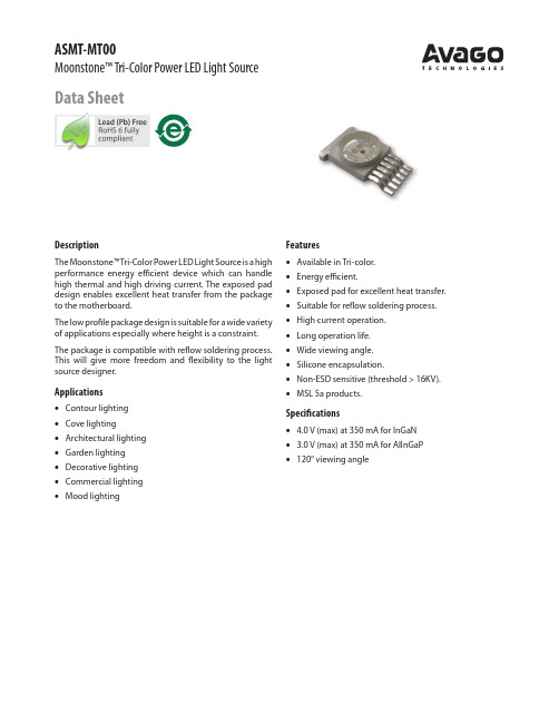
ASMT-MT00Moonstone™ Tri-Color Power LED Light SourceData SheetDescriptionThe Moonstone™ T ri-Color Power LED Light Source is a high performance energy efficient device which can handle high thermal and high driving current. The exposed pad design enables excellent heat transfer from the package to the motherboard.The low profile package design is suitable for a wide variety of applications especially where height is a constraint. The package is compatible with reflow soldering process. This will give more freedom and flexibility to the light source designer.Applications•Contour lighting•Cove lighting•Architectural lighting•Garden lighting•Decorative lighting•Commercial lighting•Mood lighting Features•Available in Tri-color.•Energy efficient.•Exposed pad for excellent heat transfer.•Suitable for reflow soldering process.•High current operation.•Long operation life.•Wide viewing angle.•Silicone encapsulation.•Non-ESD sensitive (threshold > 16KV).•MSL 5a products. Specifications• 4.0 V (max) at 350 mA for InGaN• 3.0 V (max) at 350 mA for AlInGaP•120° viewing anglePackage DimensionsDevice Selection Guide (T j = 25°C)Part NumberColorLuminous Flux, ΦV [1,2] (lm)Test Current (mA)Dice TechnologyMin.Typ.Max.ASMT-MT00Red 33.040.056.0350AlInGaP Green 43.055.073.0InGaN Blue11.513.019.5InGaNNotes:1. ΦV is the total luminous flux output as measured with an integrating sphere at 25ms mono pulse condition.2. Flux tolerance is ±10%.Notes:1. All dimensions in millimeters.2. Tolerance is ±0.1 mm unless otherwise specified.3. Metal slug is connected to the anode of Red.Part Numbering SystemColor Bin SelectionNumber of Flux Bins Starting from Selected x 2Minimum Flux BinASMT-MT00 – 0 x 1 x 2 x 3 x 4Packaging Option Note:1. Please refer to Page 6 for selection details.Absolute Maximum RatingsParameterAllnGaPInGaNUnitsDC Forward Current [1]350350mA Power Dissipation 10501400mW LED Junction Temperature125125°C Operating Metal Slug Temperature Range at 350 mA -40 to +105-40 to +105°C Storage Temperature Range -40 to +120-40 to +120°CSoldering TemperatureRefer to Figure. 10Note:1. Derate linearly based on Figure. 7 for InGaN and Figure. 8 for AlInGaP .Optical Characteristics at 350 mA (T J = 25°C)Part NumberColorPeak Wavelength,λPEAK (nm)Dominant Wavelength, λD [1] (nm)Viewing Angle, 2θ½ [2] (°)Luminous Efficiency (lm/W)Typ.Typ.Typ.Typ.ASMT-MT00Red 63662512048Green 52252712045Blue46547012011Notes:1. The dominant wavelength, λD , is derived from the CIE Chromaticity Diagram and represents the color of the device.2. θ½ is the off-axis angle where the luminous intensity is ½ the peak intensity.Electrical Characteristic at 350 mA (T J = 25°C)Dice TypeForward Voltage,V F (Volts) at I F = 350mAReverse Voltage,V R [1]Thermal Resistance, R θj-ms (°C/W) [2]Min.Typ.Max.Typ.AllnGaP 1.8 2.4 3.0Not recommended23InGaN3.23.54.020Notes:1. Not designed for reverse bias operation.2. R θj-ms is Thermal Resistance from LED junction to metal slug. All 3 colors are lighted up at once during measurement.0.00.10.20.30.40.50.60.70.80.91.0WAVELENGTH - nmR E L A T I V E I N T E N S I T Y00.20.40.60.811.21.41.6DC FORWARD CURRENT - mAR E L A T I V E L U M I N O U S F L U X (N O R M A L I Z E D A T 350 m A )05010015020025030035001234FORWARD VOLTAGE - VF O R W A R D C U R R E N T - m AAlInGaP InGaN0.10.20.30.40.50.60.70.80.91-90-60-300306090ANGULAR DISPLACEMENT - DEGREESN O R M A L I Z E D I N T E N S I T Y-0.30-0.20-0.100.000.100.200.30JUNCTION TEMPERATURE,T J - °CF O R W A R D V O L T AG E SHI F T - V (N O R M A L I Z E D A T 25°C )0.020.040.060.080.0100.0120.0140.0160.0180.0JUNCTION TEMPERATURE,T J - °CR E L A T I V E L I G H T O U T P U T - %(N O R M A L I Z E D A T 25°C )Figure 1. Relative Intensity vs. Wavelength.Figure 2. Relative Luminous Flux vs. Mono Pulse Current.Figure 3. Forward Current vs. Forward Voltage.Figure 4. Radiation Pattern.Figure 5. Forward Voltage Shift vs. Junction Temperature.Figure 6. Relative Light Output vs. Junction Temperature.Figure 7. Maximum Forward Current vs. Ambient Temperature for InGaN. Derated based on T JMAX = 125°C, R θJ-A = 30°C/W, 40°C/W and 50°C/W.Figure 8. Maximum Forward Current vs. Ambient Temperature for AlInGaP . Derated based on T JMAX = 125°C, R θJ-A = 30°C/W, 40°C/W and 50°C/W.Figure 9. Maximum Forward Current vs. Metal Slug Temperature. Derated based on T JMAX = 125°C, R θJ-MS = 20°C/W for InGaN and R θJ-MS = 23°C/W for AlInGaP .050100150200250300350400AMBIENT TEMPERATURE, T A - °CM A X AL L O W A B L E D C C UR R E N T - m A 050100150200250300350400AMBIENT TEMPERATURE, T A - °CM A X A L L O W A B L E D C C U R R E N T - m A050100150200250300350400METAL SLUG TEMPERATURE, T MS - °CM A X A L L O W A B L E D C C U R R E N T -m A T E M P E R A T U R E(Acc. to J-STD-020C)Figure 11. Recommended soldering land pattern.Figure 10. Recommended Reflow Soldering [1].Note:For detail information on reflow soldering of Avago surface mount LEDs, do refer to Avago Application Note AN1060 Surface Mounting SMT LED Indicator Components.Option Selection DetailsASMT-MT00 – 0 x1 x2 x3 x4x1 – Minimum Flux Binx2 – Number of Flux Bins Starting from Selected x1 x3 – Color Bin Selectionx4 – Packaging OptionFlux Bin Selection [x1, x2]Individual reel will contain part from 1 bin only.x1Minimum Flux BinRed Green Blue0Full DistributionA H J Dx2Number of Flux Bins Starting from Selected x1 Red Green Blue0 Full DistributionA222Flux Bin LimitBin IDLuminous Flux (lm) at I F = 350 mAMin.Max.A 5.57.0B7.09.0C9.011.5D11.515.0E15.019.5F19.525.5G25.533.0H33.043.0J43.056.0K56.073.0 Tolerance for each bin limits is ±10%Color Bin Selection [x3]Individual reel will contain part from 1 bin only.x3Color Bin CombinationRed Green Blue0 Full Distribution A, B, C and D B and C Color Bin LimitColor Bin ID Min.Max. Red Full Distribution620.0635.0 Green A515.0520.0B520.0525.0C525.0530.0D530.0535.0 Blue B465.0470.0C470.0475.0 Tolerance: ±1 nmPackaging Option [x4]Selection Option1Tape and Reel ExampleASMT-MT00-00001X1 = 0 – Full DistributionX2 = 0 – Full DistributionX3 = 0 – Red (Full Distribution), Green (A, B, C and D), Blue (B and C)X4 = 1 – Tape and Reel OptionTape and Reel – Option 1Figure 12. Carrier tape dimensions.DimValueA 08.80 ±0.10B 016.45 ±0.10K 0 3.60 ±0.1E 1.75 ±0.10F 11.50 ±0.10W 24.0 ±0.10P 16.0 ±0.10Q'ty/Reel250 unitsAll dimensions in mm.Figure 13. Carrier tape leader and trailer dimensions.POCKETS SEALED WITH COVER TAPE.*Note:Tape & Reel Packaging only applicable as per this datasheet only.+1.00Figure 14. Reel dimensions.For product information and a complete list of distributors, please go to our web site: Avago, Avago Technologies, and the A logo are trademarks of Avago Technologies in the United States and other countries.Data subject to change. Copyright © 2005-2008 Avago Technologies. All rights reserved. Handling PrecautionThe encapsulation material of the product is made of silicone for better reliability of the product. As silicone is a soft material, please do not press on the silicone or poke a sharp object onto the silicone. These might damage the product and cause premature failure. During assembly or handling, the unit should be held on the body only. Please refer to Avago Application Note AN5288 for detail information.Moisture SensitivityThis product is qualified as Moisture Sensitive Level 5a per Jedec J-STD-020. Precautions when handling this moisture sensitive product is important to ensure the reliability of the product. Do refer to Avago Application Note AN5305 Handling of Moisture Sensitive Surface Mount Devices for details.A. Storage before use– Unopened moisture barrier bag (MBB) can be stored at <40°C/90%RH for 12 months. If the actual shelf life has exceeded 12 months and the humidity indicator card (HIC) indicates that baking is not required, then it is safe to reflow the LEDs per the original MSL rating.– It is not recommended to open the (MBB) prior to assembly (e.g. for IQC).B. Control after opening the MBB– The humidity indicator card (HIC) shall be read immediately upon opening of MBB.– The LEDs must be kept at <30°C/60%RH at all time and all high temperature related process including soldering, curing or rework need to be completed within 24 hours.C. Control for unfinished reel– For any unused LEDs, they need to be stored in sealed MBB with desiccant or desiccator at <5%RH.D. Control of assembled boards– If the PCB soldered with the LEDs is to be subjected to other high temperature processes, the PCB need to be stored in sealed MBB with desiccant or desiccator at <5%RH to ensure no LEDs have exceeded their floor life of 24 hours.E. Baking is required if:– HIC “10%” indicator is not blue and “5%” indicator is pink.– The LEDs are exposed to condition of >30°C/60% RH at any time.– The LEDs floor life exceeded 24 hours.Recommended baking condition: 60±5°C for 20hrs.Disclaimer: Avago’s products and software are not specifically designed, manufactured or authorized for sale as parts, components or assemblies for the planning, construction, maintenance or direct operation of a nuclear facility or for use in medical devices or applications. Customer is solely responsible, and waives all rights to make claims against avago or its suppliers, for all loss, damage, expense or liability in connection with such use.。
台湾群创液晶显示屏,参数

0.066(W) X 0.198(H) 0.0529(W)X0.1587(H) 0.077(W)X0.231(H) 50/70/70/70 6 O'Clock 50% 500 500 25 58 40pin FPC, Parallel 24bit RGB -20~70 -30~80 60℃,90% RH MP 50/70/70/70 6 O'Clock 50% 250 500 25 TBD 50pin FPC, Parallel 24bit RGB -20~70 -30~80 40℃,90% RH WS 50/70/70/70 6 O'Clock 50% X 500 25 25 40pin FPC, Parallel 24bit RGB -20~70 -30~80 60℃,90% RH MP
Prepared :MDBU/MKT Update:2013/03/13 Size & Model Name Item Product type Screen Size Aspect Ratio Display Mode Resolution PPI ( Pixel per inch ) Module/Panel Size(mm) Active Area(mm) Dot Pitch(mm) Viewing Angle (Tpy.)θT/ θB/θL/θR Viewing direction NTSC Luminance(nits) Contrast Ratio Response Time(ms) Weight (g) Interface Operation Temperature( ℃ ) Storage Temperature (℃ ) HTHH.(op) Status AT043TN24 V.7 Module+T/P 4.3" 16:9 Transmissive 480X3(RGB)X272 128 105.5 x 67.2 x 4.05 95.04 x 53.856 0.066(W) X 0.198(H) 50/70/70/70 6 O'Clock 50% 400 500 25 58 40pin FPC, Parallel 24bit RGB -20~70 -30~80 60℃,90% RH MP 4.3"D AT043TN25 V.2 Module 4.3" 16:9 Transmissive 480X3(RGB)X272 128 105.5 x 67.2 x 2.9 95.04 x 53.856 5"DN TBD Module 5.0'' 4:3 Transmissive 640X3(RGB)X480 160 117.65 x 88.43 x 5.7 101.568 x 76.176 5.0"DW AT050TN30 FOG 5.0'' 16:9 Transmissive 480X3(RGB)X272 110 117.70 × 72.80 × 1.43 110.88 x 62.832 HE050NA-01F FOG 5.0'' 15:9 Transmissive 800X3(RGB)X480 188 115.6 × 74.38 × 1.43 108 x 64.8 0.045(W) x 0.135(H) 50/70/70/70 6 O'Clock 50% / 500 25 26 50pin FPC, Parallel 24bit RGB -20~70 -30~80 60℃,90% RH MP 5"DH EJ050NA-01G Module 5.0" 15:9 Transmissive 800X3(RGB)X480 188 120.7 x 76.3x 3.1 108 x 64.8 0.045(W) x 0.135(H) 50/70/70/70 6 O'Clock 50% 350 500 25 60 50pin FPC, Parallel 24bit RGB -20~70 -30~80 60℃,90% RH MP AT056TN53 V.1 Module 5.6'' 4:3 Transmissive 640X3(RGB)X480 144 126.5 x 100.0 x 5.7 112.896 x 84.672 0.0588(W) x 0.1764(H) 50/70/70/70 6 O'Clock 50% 350 500 25 83 40pin FPC, Parallel 18bit RGB -20~70 -30~80 40℃,90% RH MP 5.6"D AT056TN52 V.3 Module 5.6'' 4:3 Transmissive 640X3(RGB)X480 144 126.5 x 100.0 x 5.7 112.896 x 84.672 0.0588(W) x 0.1764(H) 50/70/70/70 6 O'Clock 50% 200 500 25 127.5 50pin FPC, Parallel 24bit RGB -20~70 -30~80 40℃,90% RH MP ZE065NA-01B FOG 6.5" 16:9 Transmissive 800X3(RGB)X480 150 152.10 × 86.60 × 1.43 143.40 × 76.70 0.060(W) × 0.160 (H) 50/70/70/70 6 o’clock 50% NA 500 25 TBD 50pin FPC, Parallel 24bit RGB -20~60 -30~70 40℃,90% RH WS 6.57 V.D Module 7" 16:9 Transmissive 480X3(RGB)X234 74 164.9 x 100.0 x 5.7 154.08 x 86.58 0.107(W) X 0.370(H) 40/60/60/60 6 O'Clock 50% 200 300 35 166 Analog(26 Pin FPC) -30~85 -30~85 60℃,90% RH MP AT070TN83 V.1 Module 7" 15:9 Transmissive 800X3(RGB)X480 133 165 x 104 x 4.4 152.4 x 91.44
5050RGB规格书(中文)
标示区有无由蓝色变为粉红色.如漏气或变色现象,请联系厂家或退回厂家高温除湿处理,(高温除湿 环境:120 度,6H)切勿自行处理 2-2. 打开包装前, LEDs 需储存在温度低于 30℃,湿度低于 70%RH 。 2-3. 打开包装后,在温度低于 30℃ ,湿度低于 60%RH 的情况下,且开封到焊接完成控制在 4H。 2-4. 如果吸湿材料 (硅凝胶)已经消退或是 LEDs 已经超过了储存时间, 则需要基于以下条件进行烘烤 处理: 60±5℃ / 24 小时。 3. 回流焊注意事项 3-1. 无铅锡膏的温度曲线
█ 电性与光学特性(Ta=25℃)
参数 正向电压 反向电流 发光角度 波长
光通量
符号
条件
最小 平均 最大 单位
R IF=20mA
2.0
--
2.3
VF G IF=20mA
2.9
--
3.2
V
B IF=20mA
2.9
--
3.2
IR
VR=5V
--
--
5
μA
2θ1/2
IF=3*20mA
--
120
--
deg
R IF=20mA
3-2. 回流焊不能超过两次。 3-3. 焊接期间, 加热时不要在 LEDs 上添加任何压力。 3-4. 焊接后, 正常回温至 40℃以下后才可过电流。 4. 防护措施
用适当的工具从材料侧面夹取,因产品使用硅胶封装避免在应用过程中压伤胶体,损伤内部结构造
成不良。LED 为半导体敏感器件,静电放电(ESD)或脉冲电流(EOS)可能会损害 LED。 作业机台 有效接地、作业中作好静电防护,可有效提升产品品质。贴片 LED 灯珠在生产过程中及灯具使用环境 需避免与硫.卤素.酸.醇.碱.酮肟类挥发性化合物,强氧化物.增塑剂(又名塑化剂,领苯二甲酸二辛酯 DOP 或邻苯二甲酸二丁酯 DBP,PVC 物料即含有大量增塑剂)等腐蚀性物质接触
5050 0.5W规格书

Color bin limit(If=150mA)—◎white
色区范围(IF=150mA) —白光
Bin
X
Y
Bin
X
Y
Bin
0.283 0.284
0.3035 0.332
0.295 0.297
0.315 0.3435
A0
A7
B4
0.298 0.288
0.316 0.332
0.287 0.276
0.306 0.322
Y 0.357 0.3697 0.3568 0.345 0.369 0.3827 0.3697 0.357 0.3812 0.3956 0.3827 0.369 0.321 0.342 0.332 0.3135 0.342 0.355 0.3435 0.332
White CIE Chromaticity Diagram
Our 5050 products, use silica gel packages, effectively improve the heat dissipation performance. Reliability is better than companies in general, it is a complete white combination with high brightness, low-light decay characteristics.
0.316 0.332
0.329 0.33
0.317 A6
0.308
0.319 0.311
0.329 0.345 B3
0.3455 0.3568
0.306 0.322
0.3442 0.3421
X 0.329 0.3466 0.3455 0.329 0.329 0.3478 0.3466 0.329 0.329 0.3489 0.3478 0.329 0.287 0.301 0.3035 0.2895 0.301 0.314 0.315 0.3035
5050灯珠,5050灯珠参数,...
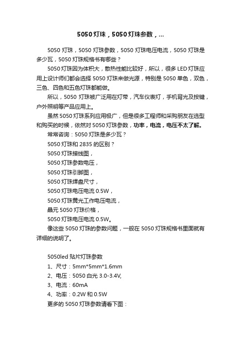
5050灯珠,5050灯珠参数,...5050灯珠,5050灯珠参数,5050灯珠电压电流,5050灯珠是多少瓦,5050灯珠规格书有哪些?5050灯珠因为体积大,散热性能比较好,所以,很多LED灯珠应用上设计师们都会选择5050灯珠来做光源,特别是5050单色,双色,三色、四色和五色灯珠都能做。
所以,5050灯珠被广泛用在灯带,汽车仪表灯,手机背光及按键,户外照明等产品应用上。
虽然5050灯珠系列应用极广,但是很多工程师和采购朋友在选型和购买的时候,依然对5050灯珠参数,功率,电流,电压不太了解。
常常咨询:5050灯珠是多少瓦?5050灯珠和2835的区别?5050灯珠接线图,5050灯珠参数电压,5050灯珠引脚图,5050灯珠焊盘尺寸,5050灯珠电压电流0.5W,5050灯珠黄光工作电压电流,晶元5050灯珠价格,5050灯珠电压电流0.5W。
像这些5050灯珠的参数问题,一般在5050灯珠规格书里面就有详细的说明了。
5050led贴片灯珠参数1、尺寸:5mm*5mm*1.6mm2、电压:5050白光 3.0-3.4V,3、电流:60mA4、功率:0.2W和0.5W更多的5050灯珠参数请看下图:5050灯珠和3030灯珠有什么区别?1、封装尺寸不同:(1)、5050灯珠封装尺寸是长、宽、高为 5.0X5.0X1.6mm。
(2)、3030灯珠封装尺寸是长、宽、高为 3.0X3.0X0.6mm。
2、颜色不同:(1)、3030灯珠一般主要是做单色灯为主。
(特别以白光1W为主)(2)、5050灯珠常做成双、三色全彩,一灯双色、三色用混合效果好。
3、功率不同:(1)、3030灯珠功率为0.2-1W。
(2)、5050灯珠功率为常规是0.2W-0.5W。
以上是5050灯珠,5050灯珠参数,5050灯珠电压电流,5050灯珠是多少瓦,5050灯珠规格书有哪些的常用参数。
5050灯珠,5050灯珠参数,5050灯珠电压电流,5050灯珠是多少瓦,5050灯珠规格书尺寸都是比较多咨询的。
LED G4灯 led g9灯
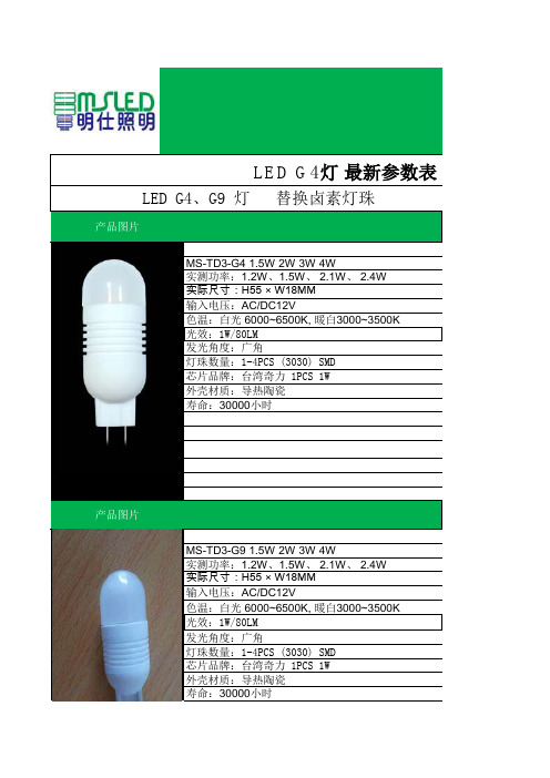
LED G4灯最新参数表 LED G4、G9 灯 替换卤素灯珠产品图片MS-TD3-G4 1.5W 2W 3W 4W实测功率:1.2W、1.5W、 2.1W、 2.4W实际尺寸:H55 × W18MM输入电压:AC/DC12V色温:白光 6000~6500K, 暖白3000~3500K光效:1W/80LM发光角度:广角灯珠数量:1-4PCS (3030) SMD芯片品牌:台湾奇力 1PCS 1W外壳材质:导热陶瓷寿命:30000小时产品图片MS-TD3-G9 1.5W 2W 3W 4W实测功率:1.2W、1.5W、 2.1W、 2.4W实际尺寸:H55 × W18MM输入电压:AC/DC12V色温:白光 6000~6500K, 暖白3000~3500K光效:1W/80LM发光角度:广角灯珠数量:1-4PCS (3030) SMD芯片品牌:台湾奇力 1PCS 1W外壳材质:导热陶瓷寿命:30000小时产品图片产品参数MS-G9-3D-2W 3W实测功率:1.8W 2.4W实际尺寸:H65 × W22MM输入电压:200-240V色温:白光 6000~6500K, 暖白3000~3500K光效:2W(180LM)3W(280LM)发光角度:360度灯珠数量:0.22W 11PCS芯片品牌:台湾晶元 芯片 SMD 5050外壳材质:外航空铝合金 + 内陶瓷寿命:30000小时产品图片MS-1D-G4-3 1W 2W 3W 4W实测功率: 2W、 2.4W实际尺寸:H42 × W18MM输入电压:AC/DC12V色温:白光 6000~6500K, 暖白3000~3500K光效:1W/80LM发光角度:150度灯珠数量:1-4PCS芯片品牌:台湾奇力 3030 SMD外壳材质:高导热铝寿命:30000小时产品图片MS-5D-G4 4W 5W实测功率:4W(2.5W) 5W(2.8W)实际尺寸:H42 × W15MM输入电压:AC/DC12V色温:白光 6000~6500K, 暖白3000~3500K光效:4W(280LM)5W(300LM)发光角度:广角灯珠数量:10PCSX0.5W芯片品牌:台湾奇力 3020贴片外壳材质:高导热铝寿命:30000小时产品图片MS-G4-3D-2.5W实际功率:2W实际尺寸:H42 × W10MM输入电压:AC/DC12V色温:白光 6000~6500K, 暖白3000~3500K光效:2.5W(230LM)发光角度:广角灯珠数量:6PCSX0.5W芯片品牌:台湾奇力 3020贴片外壳材质:高导热铝寿命:30000小时产品图片G9-1D-2W 3W实际功率:3W(2.5W)2W(2W)实际尺寸:H60 × W20MM输入电压:AC/DC-220V色温:白光 6000~6500K, 暖白3000~3500K光效:2W(150LM)3W(200LM)发光角度:120度灯珠数量:1PCSX(3W)(2W)芯片品牌:台湾奇力 COB T10外壳材质:高导热铝寿命:30000小时产品图片G4-C5D-5W实测功率:3W实际尺寸:H42 × W17MM输入电压:AC/DC12V色温:白光 6000~6500K, 暖白3000~3500K光效:5W(330LM)发光角度:广角灯珠数量:5PCSX(1W)芯片品牌:台湾奇力 COB 8.5外壳材质:高导热铝寿命:30000小时产品图片G4-1D-1W 1.5W实测功率:1W 1.5W实际尺寸:H42 × W17MM输入电压:AC/DC12V色温:白光 6000~6500K, 暖白3000~3500K发光角度:120度光效:1W(80LM)1.5W(110LM)灯珠数量:1PCSX(1W)(1.5W)芯片品牌:台湾奇力 COB 8.5外壳材质:高导热铝寿命:30000小时产品图片G4-TP3-4W 6W实测功率:2.7W 3.4W实际尺寸:H35 × W18MM输入电压:AC/DC12V色温:白光 6000~6500K, 暖白3000~3500K光效:4W(280LM)6W(380LM)发光角度:360度灯珠数量:18PCSX(0.2W) 27 PCS(0.2W)芯片品牌:台湾奇力 SMD 5050外壳材质:高导热铝寿命:30000小时产品图片G4-TP3-4W 6W实测功率:2.7W 3.4W实际尺寸:H35 × W18MM输入电压:DC12V色温:白光 6000~6500K, 暖白3000~3500K光效:6W(380LM)发光角度:360度灯珠数量:4PCSX(1.5W)芯片品牌:台湾奇力 COB 9X21 T12外壳材质:高导热铝寿命:30000小时参数表。
5050软灯条规格书

5050-60 灯/米软灯条规格书特征:1 广泛运用,易于安装与维修,寿命长2 柔性极强,易于弯变成不同形状,各种颜色可供选择3 高亮度,广视角4 节能环保5 独立线性LED 贴于带背自黏胶的PCB 板上6 每3颗LED 灯形成一个回路,不影响其他线路7 DC 或导线接头任选8 可根据客户需求定做光电性参数:型号颜色工作电压灯珠数量长度灯的间距色温光通量CHX-BS-5050-60白色12DC 60 1m 8.3mm 3000-3500 13—15LM 每米最大功率14.4W 每米最大电流 1.2A 光源5050(CREE灯珠) 工作湿度30%——85% PCB板厚度0.2mm 每组LED数量 3PCB材料聚酰亚胺最大连接长度5mPCB颜色白与电源连接方式导线发光角度120 包装方式纸箱包装光衰小于15%(一万小时)产品重量0.3KG 使用寿命10万小时防水处理方法防水储存温度-40——+80 工作温度-30——+60灯条的安装方法:1.灯条先连接到电源适配器上然后再连接到电源,从而点亮灯条。
(注意:电源适配器的功率要大于灯条的最大功率)2. 灯条先连接到开关电源的“+”、“-”极上,然后开关电源连接到交流电源上从而点亮灯条。
(注意:开关电源的功率要大于所有灯条的最大功率,开关电源的输出电压要与灯条的的工作电压一致)灯条的应用:1、节日装饰、活动会场布景、展览会场装饰、展馆装饰;2、汽车底盘装饰、车身装饰、车内装饰;3、酒店及KTV等娱乐场所装饰。
注意事项:1.禁止在超过工作电压5%(12V)的环境下使用本产品2.请不要在此产品的两端施加相反的电压3.勿压,勿扭曲;使用寿命 100000 小时4.包装:每卷5米为常规包装5. 包装方式可按照客户要求质保,售后服务说明:凡购买本司产品从出厂日起,质保贰年。
在正常使条件下,质量保证是基于产品正确保存,安装,使用和维护。
基于安装使用不当,违反产品操作过程,而引起的产品损坏,不属于本保证之内。
5050灯珠规格书

0.4386
4000K
Rank
CIE-X
0.3760
40C02 0.3859 (3900-4100K) 0.3920
0.3822
5000K
Rank
CIE-X
0.3444
50C02 0.3469 (4700-5000K) 0.3558
0.3539
6500K
Rank
CIE-X
0.3104
CIE-Y 0.424 0.4116 0.4204 0.4329
条件 =60mA
=60mA =60mA =60mA
最小
18 20 22
2.9 3.0 3.1 3.2 3.3 118
62
最大
20 22 24
3.0 3.1 3.2 3.3 3.4 123
85
单位 lm V deg -
4
4.: 03/01/2013: 03/01/2013 Rev: 01
5050 灯珠规格书
ZT5050W: 03/01/2013 Rev: 01
目录
1.产品描述 2.最大额定值 3.光电参数 4.典型光电特性曲线 5.分光标准 6.可靠性测试 7.产品规格尺寸 8.料盘结构和包装 9.回流焊 10.使用注要事项
240℃ 20-40 秒 最大 6℃/每秒 最大 8 分钟
10.使用注意事项 储存 (1) 打开包装前 在温度不超过 40℃及湿度不超过 90%RH 条件下,LED 可以保存一年,在储存的时候, 建议采用带干燥剂的防潮袋的包装方式。 (2)打开包装后 LED 需要储存在<=40℃&<=60%RH 相对湿度的条件下,我们强烈建议您从打开包装到 完成贴片整个过程在一个星期内完成。 如果有未使用完的剩余 LED,我们建议重新使用出厂时的防潮剂,并且需要重新密封。 如果干燥剂过期了,请将 LED 放在 60℃烤箱烘烤 12 小时。 LED 电极和引线框架是由表面镀了银的铜合金构成,镀银层会受到来自周围环境的破 坏,请把 LED 远离那种会腐蚀 LED 电极镀银层的环境,LED 电极被腐蚀后,会降低它的 焊接能力和光电参数。 请避免 LED 使用在温度快速变化的环境中,尤其是会发生冷凝的高湿环境中。
智能LED控制和光源电路的5050大小包装产品说明书
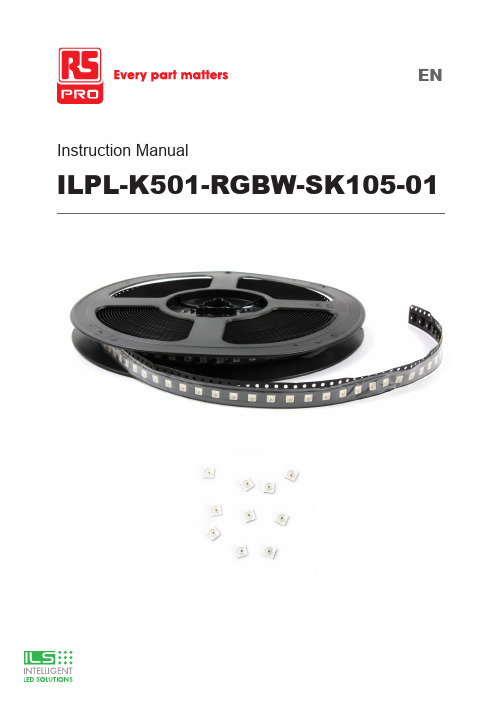
Instruction ManualILPL-K501-RGBW-SK105-01Product OverviewThe ILPL-K501-RGBW-SK105-01 is an Intelligent LED with control and light emitting circuit, all contained in a 5050 sized package.Based on the industry standard SK6182 device, the control circuit consists of signal shaping amplification, built-in constant current source, and a high precision RC oscillator.The data protocol being used is the unipolar NRZ communication mode, where the 32-bit data is transmitted from the controller to DIN of the first LED, after an internal data latch, the remaining data is passed through the internal amplification circuit and sent out of the DO port to the remaining pixels. Using ‘automatic shaping forwarding technology’ means the number of cascaded LEDs is only limited by the signal transmission speed.Applicationsz Task Lightingz Back Lightingz Desk Lightingz Garage Lightingz Accent Lightingz Under Cabinet Lightingz Bar Lightingz Refrigerationz Industrial Applicationsz PhotographyTechnical Featuresz Control circuit and the RGBW die all in one 5050 sized devicez Grey level adjusting control (256 level grey scale)z Red drive special control enhances colour balancez Transmission distance between two points can be up to 10Mz Using a typical data transmission frequency of 800 Kbps, you can achieve refresh rates of 30 frames per secTechnical Drawing (mm)Notes:1. All dimensions are in millimeters.2. Tolerance is ±0.1mm unless otherwise notedPIN configurationAbsolute Maximum Ratings (Ta=25˚,VSS=0V)The electrical parameters (unless otherwise specified, TA=-20 - +70˚C, VDD=4.5 - 5.5V, VSS=0V)The dynamic parameters (Ta=25˚C)The data transmission time (TH+TL=1.25μs±600ns)T0H0 code, high level time0.3μs±0.15μs T0L0 code, low level time0.9μs±0.15μs T1H 1 code, high level time0.6μs±0.15μs T1L 1 code, low level time0.6μs±0.15μs Trst Reset code, low level time80μsTiming waveformmode:ConnectionInputcode:The method of data transmissionThe data structure of 24bitNote: high starting, in order to send data (R7 - R6 - ...... ..W0) The typical application circuit:CIE chromaticity coordinates (ANSI Natural white)ANSI Warm White Color bin structuresStandard LED Performance Graph1020%0.0040%60%80%Forward Current(mA)Forward Voltage(V) Tj=25 °CN o r m a l i z e d L u m i n o u s F l u xF o r w a r dC u r r e n t (m A )Typical Relative Luminous Flux vs. Forward CurrentForward Voltage vs. Forward Current12040608010020%0.0040%60%80%Thermal Pad Temperature (T=25°C)N o r m a l i z e dL u m i n o u s F l u xThermal Pad Temperature vs. Relative Light Output12020%0.0040%60%80%Wavelength (nm)R e l a t i v e E m i s s i o n D i s t r i b u t i o nWavelength Characteristics7590604530150.40.20.60.81.090°Typical Radiation Pattern 120°Radiation Angle1020150150.02050150150%200406080100F o r w a r d C u r r e n t (m A )Thermal Pad Temperature vs. Forward Current200406080100Thermal Pad Temperature (°C)120TOP SMD LED Application Notes1. FeaturesThe Purposes of making OPSCO’s customers and users to have a clear understanding on the ways how to use the LED.2. DescriptionGenerally. The LED can be used the same way as other general purposed semiconductors. When using OPSCO’s TOP SMD LED, the following precautions must be taken to protect the LED.3. Cautions3.1. Dust & CleaningThis emitter has a silicone surface, There are many benefits to the silicone surface in terms of optical properties and improved reliability. However, silicone is a softer material and prone to attract dust. Whilea minimal amount of dust and debris on the LED will not cause significant reduction in illumination, steps should be taken to keep the emitter free of dust.These include keeping the LEDs in the manufacturer’s package prior to assembly and storing assemblies in an enclosed area after installing the emitters.Surface condition of this device may change when organic solvents such as trichloroethylene or acetone were applied.Avoid using organic solvent, it is recommended that isopropyl be used as a solvent for cleaning the LEDs. When using other solvents, it should be confirmed beforehand whether the solvents will dissolve the package and the resin of not.Do not clean the LEDs by the ultrasonic. When it is absolutely necessary, the influence as ultrasonic cleaning on the LEDs depends on factors such as ultrasonic power. Baking time and assembled condition. Before cleaning, a pre-test should be done to confirm whether any damage to the LEDs will occur.3.2. Moisture Proof PackageIn order to avoid the absorption of moisture during transportation and storage, LED are packed in the aluminum envelop, A desiccant is included in the aluminum envelop as it absorbs moisture. When moisture is absorbed into the AMT package it may vaporize and expand during soldering. There is a possibility that this can cause exfoliation of the contacts and damage to the optical characteristics of the LEDs. For this reason, the moisture proof package is used to keep moisture to a minimum in the package.3.3. StorageIn order to avoid the absorption of moisture, It is recommended to store SMD LED (in bulk or taped) inthe dry box (or the desiccator ) with a desiccant, Otherwise to store them in the following environment as recommended.a. Temperature: 5˚C — 30˚Cb. Humidity: 60% RH MaxIt is recommended to solder the LED as soon as possible after unpacking the aluminum envelop, But in case that the LED have to be left unused after unpacking envelop again is requested.The LED should be soldering within 1 hours after opening the package.If baking is required, A baking treatment should be performed as follows:70˚C ±5˚C for more than 24 hours.Reflow Soldering CharacteristicsIn testing, OPSCO has found S50 LEDs to be compatible with JEDEC J-STD-020C,using the parameters listed below. As a general guideline OPSCO recommends that users follow the recommended soldering profile provided by the manufacturer of solder paste used.Note that this general guideline is offered as a starting point and may require adjustment for certain PCB designs and Configurations of reflow soldering equipment.Tem per at ure(°C )L Profile Feature Lead-Based Solder Lead-Free SolderAverage Ramp-Up Rate (Ts max to Tp )3˚C/second max.3˚C/second max.Preheat: Temperature Min (Ts min)100˚C 150˚CPreheat: Temperature Min (Ts max)150˚C 200˚CPreheat: Time ( ts min to ts max )60-120 seconds 60-180 secondsTime Maintained Above: Temperature (TL)183˚C 217˚CTime Maintained Above: Time (t L)60-150 seconds 60-150 secondsPeak/Classification Temperature (T P)215˚C 240˚CTime Within 5˚C of Actual Peak Temperature ( tp)<10 seconds <10 secondsRamp-Down Rate 6˚C/second max.6˚C/second max.Time 25˚C to Peak Temperature <6 minutes max.<6 minutes max.Note: All temperatures refer to topside of the package, measured on the package body surface.Heat GenerationThermal design of the end product is of paramount importance. Please consider the heat generation of the LED when making the system design. The coefficient of temperature increase per input electric power is affected by the thermal resistance of the circuit board and density of LED placement on the board, as wellas components. It is necessary to avoid in tense heat generation and operate within the maximum rating given in this specification. The operating current should be decided after considering the ambient maximum temperature of LEDs.Electrostatic Discharge & Surge CurrentElectrostatic discharge (ESD) or surge current (EOS) may damage LED.Precautions such as ESD wrist strap, ESD shoe strap or antistatic gloves must be worn whenever handling of LED.All devices, equipment and machinery must be properly grounded.It is recommended to perform electrical test to screen out ESD failures at final inspection.It is important to eliminate the possibility of surge current during circuitry design.Moisture Proof PackageCannot take any responsibility for any trouble that are caused by using the LEDs at conditions exceeding our specifications.The LED light output is strong enough to injure human eyes. Precautions must be taken to prevent looking directly at the LEDs with unaided eyes for more than a few seconds.The formal specification must be exchanged and signed by both parties before large volume purchase begins. The appearance and specifications of the product may be modified for improvement without notice.For further information please contact ILSThe values contained in this data sheet can change due to technical innovations. Any such changes will be made without separate notification.。
晶元芯片规格书

InGaN Venus Blue LED Chip
Features:
High radiant flux Long operation life Lambertian radiation
ES-CABHV38
Symbol
Condition
Ta=25ºC Ta=25ºC --chip chip-on-tape/storage chip-on-tape/transportation ---
Rating
450 5 115 -40 ~ +85 0 ~ 40 -20 ~ +65 280(<10sec)
Unit
COPYRIGHT ©2010 Epistar Corporation. All Rights Reserved. 2/2 CC-200810-B
Applications:
Replacement lamps Architectural lighting Residential lighting
Mechanical Specification:
(1) Dimension Chip size : 38 mil x 38 mil (965±25μm x 965±25μm) Thickness :5.9 mil (150 ± 10 µm) P bonding pad x 2 : 3.9 mil (100 ± 10 µm) N bonding pad x 2 : 4.1 mil (105 ± 10 µm) (2) Metallization P electrode : Au alloy N electrode : Au alloy Backside metal : Au alloy
5050RGBLED灯珠全彩规格书88
Max.260℃ for 5 sec Max. (3min from the base of the epoxy bulb)
■Typical Electrical & Optical Characteristics(Ta=25°)
Items Symbol Condition
G,B
Min 3.0 1.9 --620 518 465 700 1800 400 ---
5℃,IF=30mA
Test Item Operating Life Test High Temperature Storage Low Temperature Storage Temp &Humidity Test
Duration 1000h
Units Tested 22
Number of Damaged 0/22
25℃~85 ℃~25℃ 3min -5min30min- 5min
50 Cycles
22
0/22
Mechanical Test
Resistance to Soldering Heat Lead Integrity
260±5℃,
10±1sec
1 time
22
0/22
Load 2.5N 0°~90°~0°
DONGGUAN TONGJIA OPTOELECTRONICS TECHNOLOGY CO., LTD
Typical Electrical/Optical Characteristics Curves (G):
Customer Service Hotline:400-676-8616
TEL:0769-8200 5999 0769-8200 2226 FAX:0769-8200 2777 E-MIAL∶tongjiacn@
LED 5050硬灯条规格书
确认后请回传,谢谢!Please confirm and fax to us ,thank you!XL-5050 LED 硬灯条产品效果展示:LED 硬灯条 5050灯珠效果 LED 硬灯条 5050灯珠效果一、 特点:1、采用高亮度SMD5050 LED 灯珠 , 铝合金外壳 , 每三个LED 为一段。
2、每条的标准长度为1M ,每条灯珠数量分别有 30PCS/M LED 灯珠 ,60PCS/M LED 灯珠 ,72PCS/M LED 灯珠3、发光颜色:红/绿/蓝/黄/白/暖白和长彩等多种颜色可供选择4、工作电压:DC12V/DC24V 两种5、防水型SMD 灯条,表面采用灌胶二、 用途:1、SMD 高亮度硬灯条适用于酒店,超薄灯箱,KTV 娱乐场所等室内装饰。
2、用于广告招牌等精品装饰领域。
3、度假装饰照明灯,显示及展览。
4、商场专柜,珠宝,首饰台及名贵钟表柜台。
三、产品规格:四、参数灯珠类型号: SMD 5050 LED 可选颜色: 红/绿/蓝/黄/白/暖白/RGB发光角度: 120度 灯珠数量: 30PCS / M 60PCS / M 72PCS / M 外形尺寸: 1000*10*2mm 按整体封存装: 裸板 V 型槽 U 型槽硬灯条套V 型槽图示硬灯条裸板图示U 型槽图示五、 注意事项:六、产品应用应用家居装饰应用KTV 装饰珠宝柜装饰●使用说明use manual:1.请先仔细阅读产品规格书,确认其使用环境是否符合规格书上的条件上,方可放心使用. Please read the specificationfirst to make sure the using condition is fit2.将产品接入电源时,请先确保开关处于闭合状态..Please shut off the switch before connect the product, then turn on3.本产品保质期为一年This product warranty for one year4.。
5050RGBW中文规格书
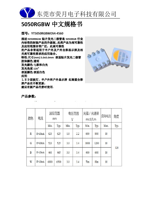
5050RGBW中文规格书型号:YT5050RGBWOS4-4560描述:5050RBGW贴片发光二极管是5050RGB行业内标准的封装产品的升级版,此类产品为高可靠性及应用范围非常广泛,此高可靠性的产品非常适用于半户外及户外全彩显示屏及相关高可靠性要求的应用场合。
特性:尺寸(mm):5.0x5.0mm 表面贴片发光二极管胶体颜色:透明发光颜色:七彩和白光发光角度:120°表面颜色:表面白色应用:LED面板灯,半户外和户外显示屏红绿蓝全彩屏产品在不断更新,建议有新产品代替时使用.产品参数:注意:所有尺寸单位为mm;如无特殊说明误差范围为±0.05mm 。
***应用注意事项特点本文件主要向顾客及用户介绍怎样如何更好的使用我司的SMD LED 产品。
描述一般来说,SMD 5050跟一般的半导体有相同的用法。
当使用荧月电子的SMD5050产品,请遵从以下的使用方法以保护SMD LED 产品。
1.清洁:不要使用不明化学液体清洗SMD LED,不明的化学液体可能会损坏SMDLED。
当必要清洗时,把SMD LED沉浸在酒精里,在正常的室温下少于1 分钟并且自然干燥15 分钟,然后才开始使用。
2.防潮湿包装为避免产品在运输及储存中吸湿,SMD LED 的包装是用防潮的铝包装袋包装,并且包装袋里面含有干燥剂及湿度卡,干燥剂主要起到控制包装袋里的湿度,湿度卡主要是起到监控包装袋里的湿度。
3.储存a.包装袋密封后贮存在条件为温度< 40℃,湿度< 60%RH,保存期为12 个月。
当超过保质期时,需要重新烘烤。
b.在开包装之前,请先检查包装袋有无漏气或湿度指示卡有无变色,如果有漏气或湿度指示卡有变色现象,请重新烘烤后再使用。
c.开封后请在以下条件使用:温度< 30℃、湿度在30%RH 以下;如果使用时间超出24小时,须做以下烘烤处理才可使用。
d.烘烤条件:产品在烘箱在温度为70℃±5℃;相对湿度≤10%RH,时间:24 小时。
5050灯带规格书

特点•5M*10mm贴片软灯条(30L E D/M).•印制电路板厚度:0.2mm•印制电路板宽度:10mm•工作电压:24V 直流.•工作电流:0.3A/M.•LED 可视角度(2θ1/2):120°•使用寿命:50000H•防水等级:IP20.应用户外照明:建筑装饰照明、标致照明、路径和轮廓标识、水下工程照明;广告照明:广告字的背光源、超薄灯箱、发光字、发光招牌;气氛照明:酒吧、KTV、咖啡厅等娱乐场所气氛渲染、工艺品照明。
室内装饰:高档专卖店、商铺等室内商业氛围照明、汽车装饰、楼梯走廊家居装饰照明;实物图静电敏感设备应用场景:LED 灯带3灯带参数光电参数压降说明:发光角度外形尺寸500010033.3310.00FPCSMD LED Res lstcr.501.753M stiker1. 所有的单位为 mm.2. 如无特殊说明,所有的公差均为3 .包装说明注意事项a)富晟LED灯带是静电敏感产品,应采取措施避免静电,诸如在使用过程中戴静电手环或防静电手套,所有的装置、设备仪器接地。
建议对组装后的LED灯带进行测试,确认LED灯带是否受到静电的破坏,确认方法为(参考):低电流或低电压,LED不能点亮或同等条件下亮度较其他LED明显偏暗为缺陷品;b)LED灯带供电电压为12V,过长使用(超过5M)压降上升,导热尾部供电电压不足,造成LED亮暗不均匀,建议使用时,超过5米从中间供电或者两头供电;c)富晟LED灯带为柔性线路板,使用过程中请勿旋转折叠,以免造成线路破坏;d)LED灯带长时间暴露在阳光或偶尔暴露在紫外线下可能导致胶体黄变;e)为保证LED灯带光电性能,请保持LED灯带发光区域表面清洁,避免手指印或其它异物覆盖;f)富晟LED灯带自带双面胶,粘贴前需保证粘贴表面平整.干净.无油;g)富晟LED灯带自带双面胶粘性强,不可在粘贴后又拉起质量保证限制●在正常使用条件下的品质保证:是基于产品的正确保存、安装、使用和维护;●由于客户安装使用不当,违反产品操作规程,而引起的产品损坏;●未经授权的修改或误用;●在指定的环境外操作本产品,或是在非指定的维修点进行配置及维修;●客户自行安装的电路造成的损坏。
- 1、下载文档前请自行甄别文档内容的完整性,平台不提供额外的编辑、内容补充、找答案等附加服务。
- 2、"仅部分预览"的文档,不可在线预览部分如存在完整性等问题,可反馈申请退款(可完整预览的文档不适用该条件!)。
- 3、如文档侵犯您的权益,请联系客服反馈,我们会尽快为您处理(人工客服工作时间:9:00-18:30)。
承认书
Samples approval sheet
客户名称(Customer name):宋生:
组件名称(Production name):贴片发光二极管
型号(Model): LMW5050W-3 编号(Part number):
日期(Date): 2011-5-14
型号Model:LMW5050W-3页码Page: 1/6一、外形图Outline dimensions:
单位Unit
公差
Tolerance
胶体颜色
Lens color
发光颜色
Emission color
mm±White白色white
※备注:承认书之编号和型号可用于查询,客户如有需要,请提供相应的编号和型号。
Remark:P/N & Model in samples approval sheet can be used to inquire,please provide corresponding P/N& model if customer need .
型号Model:LMW5050W-3页码Page:2/6
型号Model:LMW5050W-3页码Page: 3/6
四、典型光电特性曲线图Typical photoelectricity characteristic curve chart
型号Model:LMW5050W-3页码Page: 4/6
型号Model:LMW5050W-3页码Page: 6/6
型号Model:LMW5050W-3页码Page: 5/6
六、注意事项 Note
(一)引脚成形方法Led bracket forming method
(1)必需离胶体2毫米才能折弯支架。
The pin of led can be bent where is at least 2mm out of led colloid.
(2)支架成形必须用夹具或由专业人员来完成。
Must use fixture to deform the led bracket.
(3)支架成形必须在焊接前完成。
Finishing the forming of led bracket must be before soldering.
(4)支架成形需保证引脚和间距与线路板上一致。
Guarantee the gap between two pin of led tallys with LED pads in PCB when forming.(二)烙铁焊接Manual soldering
烙铁(最高30W)尖端温度不超过300℃;焊接时间不超过3秒;焊接位置至少离胶体3毫米。
The tip temperature of soldering iron don’t exceed 320℃;soldering time don’t exceed 3s and soldering position must be 3mm out of led colloid。
可靠性焊接温度(A图、B图)Soldering temperature curve chart(figure A、figure B)
A图
波峰焊
B图
回流焊
Prehea。
