AR9331芯片 2.4G无线WIFI模块用户手册
立锐升2.4G 音频无线管理接口说明书
立锐升 2.4G音频无线管理接口说明书
一、产品介绍
该产品为2.4G无线转串口通讯模块,采用半双工通讯模式,可以代替符合半双工通讯模式的串口线。
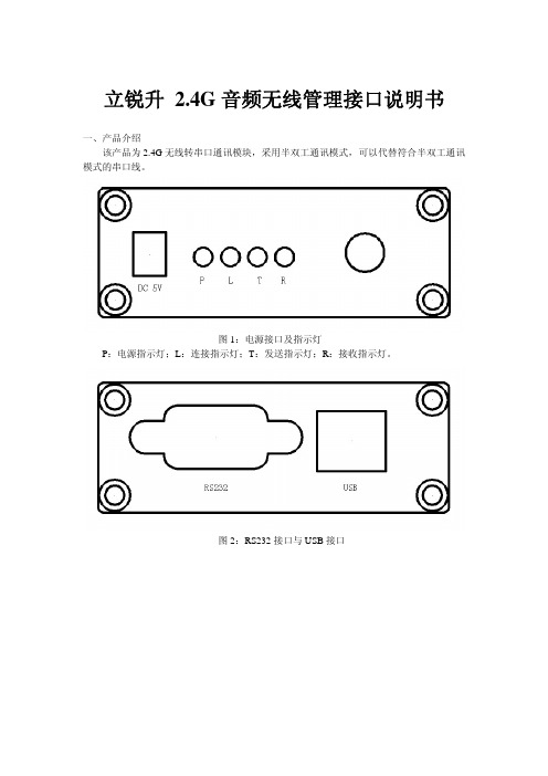
图1:电源接口及指示灯
P:电源指示灯;L:连接指示灯;T:发送指示灯;R:接收指示灯。
图2:RS232接口与USB接口
二、驱动安装
1.用USB线把无线模块与PC机连接上,此时系统会提示“检查到新硬件”如图:
2.选择“从列表或指定位置安装(高级)”然后点击下一步。
3点击“浏览”查找路径打开lrsun drivers并点击一步,驱动安装完毕。
三、使用说明
1.PC机端:用USB线连接PC机与无线模块。
2.下位机端:用串口线连接下位机与无线模块;无线模块接上5V电源。
3.线路连接完成后,电源指示灯点亮,等待4-5秒无线模块自己配对并点亮连接指示灯。
4.当连接指示灯(黄色)点亮后,无线模块即可正常通讯。
三、修改RS232串口通讯速率及无线通讯频率
1.打开RFSettting.exe软件,如图:
口选择可以在设备管理器查找串口号,如图:
3.重新连接2.4G无线模块并在5秒内点击“连接”,结果显示如下图:
注:如果在5秒内没点击“连接”则要断开USB接口并重新接上!!!
4.如图所示:可以RS232串口波特率进行修改,2.4G无线模块通讯频率修改(修改值的范围0-125)
注:修改无线通讯频率一定要两个模块同时修改为同样的数值,否则会导致无线通讯无法配对,不能正常工作。
5.点击“修改设置”参数自动保存,如图:
6.点击“断开”断开连接并拔掉USB连接线。
数字国际XBee RR DigiMesh RF模块使用说明书
DIGI INTERNATIONAL9350 Excelsior Blvd, Suite 700Hopkins, MN 55343, USA+1 (952) 912-3444 | +1 (877) 912-3444XBee RR DigiMesh Release NotesXBee RR DigiMeshVersion 3011 - September 30, 2022INTRODUCTIONThese release notes document changes made to the DigiMesh firmware on the XBee RR RF modules.[Product Information] (Product information page coming soon)DocumentationSupportSUPPORTED PRODUCTSXBRR-24 - XBee RR 2.4 GHz radio moduleMicro (MMT)Surface Mount (SMT)Through Hole (THT)KNOWN ISSUES1. The Diagnostic counts for transmissions (EA and TR) are not always as expected because sometimesthere is an extra network retry. [XBHAWKDM-200]2. The FT flow control threshold may not be calculating number of bytes properly. If FT is set to too low ofa value (less than 0x20), CTS will assert indefinitely. [XBHAWKDM-611]3. If a data transmission is attempted immediately after boot, there is a chance that the packet will bedropped. A small delay after a power cycle should alleviate this issue. [XBHAWKDM-659]4. Duplicate packets can occur if streaming unicast data across multiple synchronous sleep cycles.[XBHAWKDM-739]5. Self-addressed OTA updates may be unreliable. When updating a local device, the serial firmware updateprocess should be used. [XBHAWK-337]6. When using pins P5 and/or P6 for digital outputs the sleep current will be an additional ~15 uA for eachof the pins configured an output. [XBHAWK-926]7. C8 bit 3 is the compatiblity bit to allow synchronous sleep timing to work with legacy XBee S1 modules.But, it no longer works. When it is used, the modules will not stay synchronized, whether or not legacy XBee S1 modules are in the network. [XBHAWKDM-947]UPDATE CONSIDERATIONSXCTU (XBee Configuration and Test Utility) is recommended for updating the firmware of your radio module to the latest firmware version: /xctuInitiating an OTA firmware update will erase the file system of the target device.The file system will need to be formatted after a firmware update before it can be utilized. If a serial firmware update was performed, the file system and bundled code on the device is retained but can only be accessed by the version of firmware that was active at the time it was formatted.Example: If the file system was formatted for version 3010, it would not be accessible after a serial firmware update to 3011. To make use of the file system, it should be formatted for version 3011. If instead the file system is left untouched and the firmware is serially downgraded back to 3010, the file system from before the firmware update would be accessible.The following files are included in XBee RR RF firmware releases:FirmwareGBL: Firmware image for gateways and OEM serial updatesOTA: Firmware image for OTA firmware updatesOTB: Firmware + bootloader image for OTA updatesConfigurationXML: XCTU-NG configuration fileUPDATE BEST PRACTICESDigi recommends the following best practices:1. Test the new release in a controlled environment with your application before you update productiondevices.2. Unless otherwise noted, apply updates in the following order:1. Device firmware2. Modem firmware3. Configuration4. ApplicationDigi recommends Digi Remote Manager for automated device updates. For more information, go tohttps:///products/iot-software-services/digi-remote-manager.If you prefer manually updating one device at a time, follow these steps:Serial firmw are updates:Invoke the bootloader using one of two methods:Issue the %P AT CommandUsing hardware flow control linesInterface with the bootloader at 115200 baud and transfer a bootloader or firmware image as per the user guide.An XBee MultiProgrammer is available for serial firmware updates in a production environment.OTA firmw are/file system updates:Refer to the user guide for information on performing an OTA firmware and file system update.The OTA firmware update process for XBee 3 and XBee RR is the same across all supported RF firmwares and utilizes ZCL frames. To perform an OTA bootloader update, use the supplied *.OTB file, which is a combined firmware + bootloader image. The *.OTA file is just the firmware.The XBee Network Assistant can be used to manage your network and optimize it’s configuration prior to performing an OTA update.TECHNICAL SUPPORTGet the help you need via our Technical Support team and online resources. Digi offers multiple support levels and professional services to meet your needs. All Digi customers have access to product documentation. firmware, drivers, knowledge base and peer-to-peer support forums.Visit us at https:///support to find out more.CHANGE LOG3011 - XBee RR DigiMesh 2.4 (September 30, 2022)This is a recommended releaseBootloader version: 1.11.5MMT Hardware revision: BSMT Hardware revision: ATH Hardware revision: ANEW FEATURESAdded support for the RR Through-Hole variant.ENHANCEMENTSN/ASECURITY FIXESN/ABUG FIXES1. Fixed an issue that would prevent the module from sleeping when SSEL is configured as the wakeup pinand the UART is being used as the communication port. [XBHAWK-953]2. Fixed a watchdog issue that occurred when attempting to sleep with RTS de-asserted and pending datawaiting to be transmitted over the UART. [XBHAWK-955]3010 - XBee RR DigiMesh 2.4 (April 18, 2022)This is the initial releaseBootloader version: 1.11.5MMT Hardware revision: ANEW FEATURESN/AENHANCEMENTS1. The over-voltage detection limit is set for 3.85 volts which will output an API 0x8A Modem status of0x0D value when the voltage limit is exceeded. [XBHAWK-924] Note: Xbee3 DM product has an over-voltage limit of 3.7 volts.SECURITY FIXESN/ABUG FIXESN/ARelease Notes Part Number: 93001361。
RFM76 V1.0 2.4G收发一体模块规格说明书
2.4G收发一体模块RFM76规格说明书目录1产品概述 (3)2模块特点 (3)3应用范围 (4)4模块引脚分布 (5)5极限值 (6)6电气特性 (6)7模块尺寸图 (7)8订购信息 (7)1产品概述RFM76 是一款低成本,高集成度的2.4G的无线收发模块。
集成发射机,接收机,频率综合器,GFSK调制解调器。
发射机支持功率可调,接收机采用数字扩展通信机制,在复杂环境和干扰条件下,可以达到优良的收发性能。
外围电路简单,只需搭配MCU以及少数外围被动器件。
模块传输GFSK信号,发射功率最大可以到3dbm.接收机采用低中频结构,接收灵敏度可以达到***************。
模块的发射接收FIFO寄存器可以和MCU进行通信,存储数据,然后空中传输。
它内置了CRC,重传机制,可以大大简化系统设计并优化性能。
数字基带支持2线I2C接口。
2模块特点⚫频率范围:2400-2482Mhz⚫调制解调方式:GFSK⚫灵敏度:************⚫电压范围:2.2-3.7V⚫接收电流:20mA⚫支持2M调整IIC通讯⚫支持跳频⚫1Mbps时同步位为32bits, 16bits; 250Kbps, 125Kbps, 62.5Kbps时同步位为32bits, 16bits。
推荐使用32bits,容错1bits。
3应用范围⚫遥控⚫无线键盘鼠标⚫无线组网⚫智能家居⚫工业和商用近距离通信⚫IP电话,无绳电话⚫机器间相互通信4模块引脚分布图1模块引脚分布图表1. RFM76 模块脚位定义脚位名称功能说明1 VCC 电源2 GND 地3 CLK I2C 时钟输入脚4 DATA I2C data输入脚5极限值参数符号最小值典型值最大值单位工作电压VDD 2.2 3.3 3.7 V工作温度T -20 85 ℃存储温度T -55 +125 ℃输入射频信号强度Pin 1 +10 dbm IO电压V -0.3 +3.7 VNotes:1输入射频信号极限值表示模块在超出此条件工作时,可能会损坏。
2.4G数字无线教学麦 一拖一
2.4数字无线教学麦一. 特点1. 工作频段:ISM2.4GHz自由频段。
2. 预置信道数20个。
3. 20K采样分辨率16bit4. 频响:20Hz~16KHz5. 音频时延<1.5mS。
6. GFSK数字调制/解调。
7. 信噪比80dB,动态范围81dB,接收灵敏度-90dBm8. 内置PCB天线可减少成本与研发时间。
9. 低耗电量适合移动式产品应用。
10. 信道质量不好,误码率高时自动静音。
11. 10dBm 射频输出功率,可减少干扰相同频段中的其它设备。
12. 信道分离度@1KHz:90dB13. 传输距离空旷地带50米以上(静态)。
14. 带麦克风接口,可做无线麦克风。
二、功能特点:1、性能可靠的配对方式1)、开机自动近距离配对2)、双向配对,自动锁住最近的接收设备3)、每次开机产生新 ID码2、超强抗干扰能力3、超级低功耗10dBm的发射功率,20米的有效使用范围,工作的电流少于 30mA4、自动组网注:(1)、系统里的接收器与接收器的安装距离在8米以上,若无法满足需要申明。
(2)、发射器与接收器的配对请在2米内操作三. 規格操作说明:配对接收设备安装在每间教室,老师上课时,走到接收器的2米内打开发射器电源,听到连接提示就便可使用。
调节音量使用过程中可以通过发射器上面的音量加、减键调节合适的音量外置音频发射上面配有一个外置的音频输入口,使用时需要按中间的“麦克风/音频”切换键。
低电提示:低电提示红灯2.5秒钟闪一下,低电提示开始后,发射器还能再用60分钟后再自动关闭LED状态指示:发射器有两颗灯:蓝灯和红灯蓝灯指示机器工作的状态1)关闭电源:蓝灯熄灭2)打开电源,处于配对状态:蓝灯快闪3)打开电源,处于连接状态:麦克风模式:蓝灯每2.5秒闪两次音乐模式:蓝灯每2.5秒闪一次红灯指示机器充电的状态1)充电时红灯亮2)充满时红灯灭3)低电时红灯2.5秒钟闪一下。
南京物联无线模块使用说明
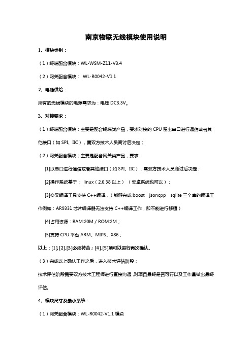
南京物联无线模块使用说明1、模块类别:(1)终端配合模块:WL-WSM-Z11-V3.4(2)网关配合模块:WL-R0042-V1.12、电源供给:所有的无线模块的电源需求为:电压DC3.3V。
3、对接要求:(1)终端配合模块:主要是配合终端类产品,要求对接的CPU留出串口进行通信或者其他接口(如SPI、IIC),需双方技术人员商讨后决定;(2)网关配合模块;主要是配合网关类产品,要求:[1]以串口进行通信或者其他接口(如SPI、IIC),需双方技术人员商讨后决定;[2]操作系统基于:linux(2.6.38以上)(安卓系统也可以);[3]交叉编译工具支持C++编译,(能够完成boost jsoncpp sqlite三个库的编译工作例如:AR9331芯片编译器无法支持C++编译工作,即不能进行移植)[4]占用资源:RAM:20M/ROM:2M;[5]支持CPU平台ARM、MIPS、X86;以上:[1],[2],[3]必须符合;[4],[5]项可以进行再次确认。
(3)完成以上确认工作之后,进入技术评估阶段:技术评估阶段需要双方技术工程师进行直接沟通,对项目最终是否可行以及工作量做出最终评估。
4、模块尺寸及最小系统:(1)网关配合模块:WL-R0042-V1.1模块图2-1WL-R0042-V1.1模块尺寸图2-2WL-R0042-V1.1模块管脚定义及最小系统(2)终端配合模块:WL-WSM-Z11-V3.4图2-3WL-WSM-Z11-V3.4模块尺寸图2-4WL-WSM-Z11-V3.4模块模块管脚定义及最小系统说明:图2-2与图2-4为两种模块的管脚定义与最小系统,图中的红色框部分为板载天线,Dedugport为模块的调试接口!5、PCB布板及焊接要求:考虑到板载天线的信号强弱问题,因此要求在对接项目中将模块直接布在对方PCB上时,给模块的天线留出净空区域(即直接挖空或要求不覆铜),尺寸以天线的大小略大为宜。
DVER 1.0 DL-24PA 远距离 2.4G 无线收发模块说明书
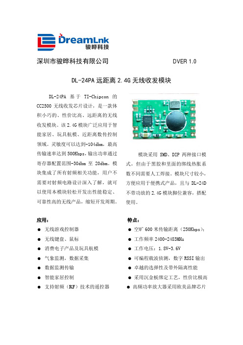
深圳市骏晔科技有限公司DVER 1.0 DL-24PA远距离2.4G无线收发模块DL-24PA基于TI-Chipcon的CC2500无线收发芯片设计,是一款体积小巧的、性价比高、远距离的无线收发模块。
该2.4G模块广泛应用于智能家居、玩具航模、近距离数传控制领域。
灵敏度可以达到-104dbm,最高传输速率达到500Kbps,输出功率通过寄存器配置范围-30dbm至20dbm。
模块集成了所有射频相关功能,用户不需要对射频电路设计深入了解,就可以使用本模块轻松开发出性能稳定、可靠性高的无线产品,缩短开发周期。
模块采用SMD、DIP两种接口模式,但由于黑胶和里面的绑线热胀系数不同需要人工焊接。
模块尺寸较小,方便应用于便携式产品,且与DL-24D 不带功放的2.4G模块脚位兼容,搭配使用。
应用: 特点:● 无线游戏控制器● 空旷600米传输距离(250Kbps);● 无线键盘、鼠标● 工作频率2400-2483MHz● 消费电子产品及玩具航模● 工作电压:1.8V-3.6V● 气象监测,数据采集● 可编程载波侦测,数字RSSI输出● 数据监测传输● 卓越的选择性及带外隔离性能● 智能家居控制● 采用沉金板绑定工艺,性价比极高● 支持射频(RF)技术的遥控器● 高频功率放大器采用欧美品牌芯片使用本模块产品前,注意以下重要事项:仔细阅读本说明文档本模块属于静电敏感产品,安装测试时请在防静电工作台上进行操作。
本模块默认使用外接天线,天线可选用导线天线或者标准的UHF天线,具体天 线的客户请根据实际情况进行选择,如果所应用的终端产品是金属外壳,请务 必把天线安装于金属外壳之外,否则会导致射频信号严重衰减,影响有效使用距离。
金属物体及导线等应尽量远离天线。
安装模块时,附近的物体应保证跟模块保持足够的安全距离,以防短路损坏。
绝不允许任何液体物质接触到本模块,本模块应在干爽的环境中使用。
使用独立的稳压电路给本模块供电,避免与其他电路共用,供电电压的误差不应大于5%。
AR9331模块规格书-4zx
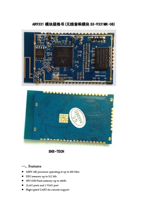
AR9331模块规格书(无线音响模块SX-9331MK-08)SHX-TECH一、Features● MIPS 24K processor operating at up to 400 Mhz.● DD2 memory up to 512 Mb.● SPI NOR Flash memory up to 64Mb.● 1LAN ports and 1 WAN port● High-speed UART for console support● I2S audio interface● USB 2.0 host/device mode support● GPIO/LED support● SPI support.二、Hardware Specifications芯片解决方案CPU:AR9331 RF:AR9331CPU主频400MHzDDR 64Mbyte DDR2闪存8Mbyte SPI FLASH遵循标准IEEE802.3u MDI / MDIX 10/100 快速以太网IEEE802.11b/g 无线LAN接口IEEE 802.11n 无线LAN标准网络接口LAN:1 x 10/100M Auto MDI/MDIX 插针接口WAN:1 x 10/100M Auto MDI/MDIX 插针接口(可以复用为LAN口)软件功能接口I2SUSB 2.0JTAGUART接口47PIN 邮标孔焊盘(PIN 间距为2.0mm)Data rate 11b: 11M, 5.5M, 2M, 1Mbps11g: 54M, 48M, 36M, 24M, 18M, 12M, 9M, 6Mbps11N:6.5M, 13M, 13.5M,19.5M, 26M,27M, 39M, 40.5M,52M, 54M,58.5M, 65M,81M,108M,121.5M,135M,150MbpsTransmission mode DSSSModulation OFDM/BPSK/QPSK/CCK/DQPSK/DBPSK Frequency Range 2412 MHz ~ 2472MHz(channel 1 ~ channel 13) 供电需求 3.3V,1APower consumption ≦3WRF Power @25℃(±2dB) 802.11b 19 ± 2dBm @EVM -20dBm802.11g 6-24Mbps 17 ± 2dBm36-48Mbps 16 ± 2dBm54Mbps 15± 2dBm @EVM -25dBm 802.11n HT20 MCS 7 14± 2dBm @EVM -28dBm HT40 MCS 7 14 ± 2dBm @EVM -28dBmReceiver sensitivity IEEE802.11b11Mbps≦-83dBmIEEE 802.11g54Mbps≦-70dBmIEEE 802.11nHT 20MCS 7≦-65dBmHT 40MCS 7≦-62dBm尺寸53.2*30MM环境Operating Temperature: -10℃~45℃Storage Temperature: -40℃~85℃Operating Humidity: 10%~90% non-condensingStorage Humidity: 10%~90% non-condensing 环保遵循RoHs标准三、Pin Description:四、Dimensions and Footprint:五、接口参考电路:1、以太网接口电路:2、LED指示灯电路:3、复位电路:。
AR9331模块(ITM-AP03)规格书
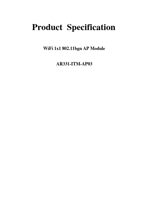
Product Specification WiFi 1x1 802.11bgn AP ModuleAR9331-ITM-AP03General DescriptionThe module ITM-AP03 is a complete, small form factor 802.11 b/g/n Wi-Fi Solution optimized for low power, low-cost, and highly integrated AP and consumer electronic devices, the module integrates all Wi-Fi functionality in a package friendly to low-cost PCB design, requiring only a few external 3.3V power supply and connection to antenna.The module based on the single chip AR9331 which integrates an 802.11n 1x1 MAC/BB/ radio with internal PA and LNA. It supports 802.11n operations up to 72 Mbps for 20 MHz and 150 Mbps for 40 MHz channel respectively, and IEEE 802.11b/g data rates.The module support AP mode and client mode at the same time and include mass service application software to reduce the research and design work of customer.FeaturesMIPS 24K processor operating at up to 400 Mhz. DD2 memory up to 512 Mb.SPI NOR Flash memory up to 64Mb.1LAN ports and 1 WAN portHigh-speed UART for console supportI2S audio interfaceUSB 2.0 host/device mode supportGPIO/LED supportSPI support.RF Performance Tx Power--Pin Description1VDD_3.3V 3.3V input 1000mA, recommended voltage 3.3V,Min2.97V, MAX 3.63V2GND GROUND3GPIO_23KEY_INPUT, be free for customer defined.4WAN_PORT_RX+Ethernet port5I2S_WS(GPIO_19)Word select for stereo6WAN_PORT_RX-Ethernet port7I2S_MICIN(GPIO_22)I2S Data input8WAN_PORT_TX+Ethernet port9I2S_MCK(GPIO_21)Master clock10WAN_PORT_TX-Ethernet port11I2S_SD(GPIO_20)Serial data input/output12LAN_PORT0_RX+Ethernet port13I2S_CK(GPIO_18)Stereo clock14LAN_PORT0_RX-Ethernet port15USB +USB signal, carries USB data to and from the USB 2.0 PHY 16LAN_PORT0_TX+Ethernet port17USB -USB signal, carries USB data to and from the USB 2.0 PHY 18LAN_PORT0_TX-Ethernet port19LED7(GPIO_27)SYSTEM LED20GND GROUND21LED8(GPIO_26)JMP_START LED22VDD_2.0V OUTPUT Power supply output for peripheral network transformer23RESET_CONFIG(UART_CTS) (GPIO_12)resets the firmware to its default configuration, it has a internal 10k drop down resistance, and trigger while Pulling up24VDD_2.0V OUTPUT Power supply output for peripheral network transformer25JUMPSTART(UART_RTS) (GPIO_11)KEY_INPUT to start WPS function, it has a internal 10k drop down resistance, and trigger while Pulling up26GND GROUND27GND GROUND28SPI_MISO SPI serial interface29VDD_3.3V 3.3V input 1000mA, recommended voltage 3.3V,Min2.97V, MAX 3.63V30SPI_CLK SPI serial interface31VDD_3.3V 3.3V input 1000mA, recommended voltage 3.3V,Min2.97V, MAX 3.63V32SPI_MOSI SPI serial interface33LED6 (GPIO_17)WLAN LED34LED2 (GPIO_13)LAN_PORT0_LED35LED1 (GPIO_1)USB LED36LED0 (GPIO_0)Wireless LED37UART_RX (SPI_CS1)Serial data in38UART_TX (SPI_CS2)Serial data out39GND GROUND40GND GROUNDElectrical Characteristics-Absolute Maximum Ratings-Recommended Operation ConditionsMechanical Drawing & Mechanical Sizecustomer can select using the inner antenna or using a external antenna by RF connector receptacle。
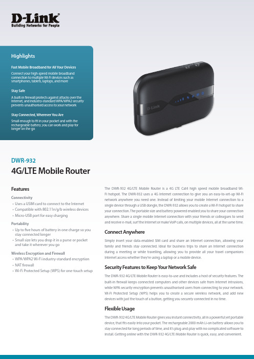
DWR-932 4G LTE 移动路由器用户手册说明书
4G/L TE Mobile RouterDWR-932The DWR-932 4G/LTE Mobile Router is a 4G LTE Cat4 high speed mobile broadband Wi-Fi hotspot. The DWR-932 uses a 4G Internet connection to give you an easy-to-set-up Wi-Fi network anywhere you need one. Instead of limiting your mobile Internet connection to a single device through a USB dongle, the DWR-932 allows you to create a Wi-Fi hotspot to share your connection. The portable size and battery powered enabled you to share your connection anywhere. Share a single mobile Internet connection with your friends or colleagues to send and receive e-mail, surf the Internet or make VoIP calls, on multiple devices, all at the same time.Connect AnywhereSimply insert your data-enabled SIM card and share an Internet connection, allowing your family and friends stay connected. Ideal for business trips to share an Internet connection during a meeting or while travelling, allowing you to provide all your travel companions Internet access whether they’re using a laptop or a mobile device.Security Features to Keep Y our Network SafeThe DWR-932 4G/LTE Mobile Router is easy-to-use and includes a host of security features. The built-in firewall keeps connected computers and other devices safe from Internet intrusions, while WPA security encryption prevents unauthorised users from connecting to your network. Wi-Fi Protected Setup (WPS) helps you to create a secure wireless network, and add new devices with just the touch of a button, getting you securely connected in no time.Flexible UsageThe DWR-932 4G/LTE Mobile Router gives you instant connectivity, all in a powerful yet portable device, that fits easily into your pocket. The rechargeable 2000 mAh Li-on battery allows you to stay connected for long periods of time, and it’s plug-and-play with no complicated software to install. Getting online with the DWR-932 4G/LTE Mobile Router is quick, easy, and convenient.FeaturesConnectivity• Uses a USIM card to connect to the Internet • Compatible with 802.11n/g/b wireless devices • Micro-USB port for easy charging Portability• Up to five hours of battery in one charge so you stay connected longer• Small size lets you drop it in a purse or pocket and take it wherever you go Wireless Encryption and Firewall• WPA/WPA2 Wi-Fi industry-standard encryption • NAT firewall• Wi-Fi Protected Setup (WPS) for one-touch setupD-Link European Headquarters. D-Link (Europe) Ltd., First Floor, Artemis Building, Odyssey Business Park, West End Road, South Ruislip HA4 6QE, United Kingdom. Specifications are subject to change without notice. D-Link is a registered trademark of D-Link Corporation and its overseas subsidiaries. All other trademarks belong to their respective owners. ©2018 D-Link Corporation. All rights reserved. E&OE. Updated January 2018For more information: 。
wifi芯片型号有哪些_wifi芯片型号汇总
标准:802.11a/g/b/n
频段:2.4GHz
最高传输速率:150Mbps
功能:单WiFi
应用:消费类电子设备(TV、DVD播放器、蓝光播放器等)
手机和其他移动应用
4、88W8797
标准:802.11ac
频段:2.4/5GHz
最高传输速率:300Mbps
功能:WiFi+BT4.0+FM
6、BCM4335
标准:802.11a/b/g/n/ac
频段:2.4/5GHz
最大传输速率:433.3Mbps
功能:WiFi+BT4.0+FM
应用:智能手机,平板电脑,网络播放器等
备注:三星手机i9500,note3,19508,Galaxy S4,HTC One有使用
7、BCM4336
标准:802.11b/g/n
2、AR9271
标准:802.11b/g/n
最大传输速率:150Mbps
应用:笔记本无线网卡,外置扩展无线网卡
应用:网关、机顶盒、游戏控制台、打印机、IP摄像机等
3、AR9285
此芯片做的WiFi模组如下:
(1)海华模组AW-NE785H
4、AR9331
标准:802.11n
频段:2.4GHz
功能:单WiFi
标准:802.11 b/g/n
频段:2.4GHz
12、BCM43340
标准:802.11a/b/g/n
频段:2.4/5GHz
功能:WiFi+BT4.0
13、BCM43241
标准:802.11a/b/g/n
频段:2.4/5GHz
最大传输速率:300Mbps
功能:WiFi+BT4.0+FM
2.4G和 5.8G无线网桥资料
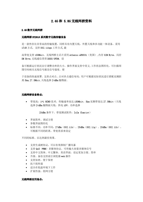
2.4G和 5.8G无线网桥资料2.4G数字无线网桥无线网桥ST2510系列数字无线传输设备是一款性价比非常高的传输装置,同样具有内置天线、外置天线和多功能一体设备。
采用1T1R方式,支持802.11bgn工作方式,最高带宽支持150Mbit。
无线网桥主芯片采用Atheros AR9331(美国),内存32M Byte、闪存8M Byte,无线通信类型DSSS/OFDM。
设备可根据运行状况自行调整功率的大小,操作界面支持中英文,工作状态图形化。
可扫描周围空间相关无线信号源及信号强度,便于设备的快速部署。
支持点对点、点对多点通信布局,用户可根据实际状况进行搭配实测距离5km,27.5Mbit,天线选择24dBm抛物面。
无线网桥设备特点:•带宽高:1*1 MIMO技术,传输速率高达150Mbit,5km实测带宽达27.5Mbit(天线选择24dBm抛物面天线,供电18V,功率选择23dBm条件下,带宽测试软件:IxIa Chariot)•界面简单、调试方便•参数界面图形化•标准不同,功率不同:27dBm(802.11b)、25dBm(802.11g)、23dBm(802.11b),可根据不同的距离、带宽需求来设定不同的标准、以达到最佳效果。
•支持生成树协议,可以有效抑制广播风暴•支持QoS(WMM)多媒体协议,可传输大容量多媒体信号•支持中文简体、中文繁体、英语界面,设定更加方便、简单•升级、备份支持流行浏览器web操作•支持加密,便于保密•抗干扰性强•适合在低温环境下工作•扩展性强、组网方便无线网桥应用场合:建筑工地、矿区、水利、油田、大型水面养殖场所、大型农场、森林防火、部队演习等恶劣环境高清视频监控、多媒体信号传输校园、大型办公场所、商场、酒店等公共场所无线上网信号覆盖建筑物之间的联网可传输视频、音频、网络、数据等大容量数据传输选配天线:18dB 平板天线24dB抛物面天线无线网桥设备参数:外接天线建议:2.4G全向天线5dBi 全向玻璃钢天线(水平360°,垂直32°)8dBi全向玻璃钢天线(水平360°,垂直16°)9dBi全向玻璃钢天线(水平360°,垂直13°)10dBi全向玻璃钢天线(水平360°,垂直10.5°)12dBi全向玻璃钢天线(水平360°,垂直9°)15dBi 全向玻璃钢天线(水平360°,垂直8°)全向天线传输距离大概可达2km左右,能量比较分散,一般不会太远。
捷麦 CW10 型 WiFi 模块用户手册说明书
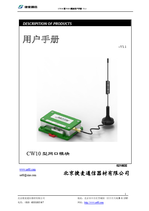
--V1.1CW10型网口模块 DESCRIPITION OF PRODUCTS北京捷麦通信器材有限公司 *************版权声明北京捷麦通信器材有限公司版权所有,并保留对本手册及本声明的最终解释权和修改权。
本手册的版权归北京捷麦通信器材有限公司所有。
未得到北京捷麦通信器材有限公司的书面许可,任何人不得以任何方式或形式对本手册内的任何部分进行复制、摘录、备份、修改、传播、翻译成其它语言、将其全部或部分用于商业用途。
免责声明本手册依据现有信息制作,其内容如有更改,恕不另行通知。
北京捷麦通信器材有限公司在编写该手册的时候已尽最大努力保证其内容准确可靠,但不对本手册中的遗漏、不准确或印刷错误导致的损失和损害承担责任。
我们会经常对手册中的数据进行检查,并在后续的版本中进行必要的更正。
欢迎您提出宝贵意见。
技术支持北京捷麦通信器材有限公司建立了以总部技术支持中心、区域技术支持中心和本地技术支持中心为主体的完善的服务体系,并提供电话热线服务。
您在产品使用过程中遇到问题时可随时与北京捷麦通信器材有限公司技术支持服务热线联系。
此外,您还可以通过北京捷麦通信器材有限公司网站及时了解最新产品动态,以及下载需要的技术文档。
北京捷麦通信器材有限公司:地址:北京市丰台区芳城园一区日月天地B座1505邮编:100017电话:************/6/7传真:************E-mail:****************网站:阅读指南手册目标通过阅读该用户手册,可以了解CW10的外观结构及安装、知道CW10如何与PC计算机连接通信、熟悉CW10的各种工作模式及其参数意义,会使用参数配置软件完成对CW10的参数操作,依据常用功能的调试流程应用CW10产品的基本功能。
使得用户完全能够应用本产品所提供的所有功能。
阅读对象本手册为具有一定工控背景知识的工程人员、安装人员及电气人员编写,其内容涵盖了CW10的安装、功能模式讲解和调试等信息。
泰利特LTE模块- 瑞萨- AR933x- 4.1.4- 发布说明说明书
]IoT AppZone Release NotesRelease Version 4.1.480496DSW10114A r8 – 2019-09-121 6SPECIFICATIONS ARE SUBJECT TO CHANGE WITHOUT NOTICENOTICEWhile reasonable efforts have been made to assure the accuracy of this document, Telit assumes no liability resulting from any inaccuracies or omissions in this document, or from use of the information obtained herein. The information in this document has been carefully checked and is believed to be reliable. However, no responsibility is assumed for inaccuracies or omissions. Telit reserves the right to make changes to any products described herein and reserves the right to revise this document and to make changes from time to time in content hereof with no obligation to notify any person of revisions or changes. Telit does not assume any liability arising out of the application or use of any product, software, or circuit described herein; neither does it convey license under its patent rights or the rights of others.It is possible that this publication may contain references to, or information about Telit products (machines and programs), programming, or services that are not announced in your country. Such references or information must not be construed to mean that Telit intends to announce such Telit products, programming, or services in your country. COPYRIGHTSThis instruction manual and the Telit products described in this instruction manual may be, include or describe copyrighted Telit material, such as computer programs stored in semiconductor memories or other media. Laws in the Italy and other countries preserve for Telit and its licensors certain exclusive rights for copyrighted material, including the exclusive right to copy, reproduce in any form, distribute and make derivative works of the copyrighted material. Accordingly, any copyrighted material of Telit and its licensors contained herein or in the Telit products described in this instruction manual may not be copied, reproduced, distributed, merged or modified in any manner without the express written permission of Telit. Furthermore, the purchase of Telit products shall not be deemed to grant either directly or by implication, estoppel, or otherwise, any license under the copyrights, patents or patent applications of Telit, as arises by operation of law in the sale of a product.COMPUTER SOFTWARE COPYRIGHTSThe Telit and 3rd Party supplied Software (SW) products described in this instruction manual may include copyrighted Telit and other 3rd Party supplied computer programs stored in semiconductor memories or other media. Laws in the Italy and other countries preserve for Telit and other 3rd Party supplied SW certain exclusive rights for copyrighted computer programs, including the exclusive right to copy or reproduce in any form the copyrighted computer program. Accordingly, any copyrighted Telit or other 3rd Party supplied SW computer programs contained in the Telit products described in this instruction manual may not be copied (reverse engineered) or reproduced in any manner without the express written permission of Telit or the 3rd Party SW supplier. Furthermore, the purchase of Telit products shall not be deemed to grant either directly or by implication, estoppel, or otherwise, any license under the copyrights, patents or patent applications of Telit or other 3rd Party supplied SW, except for the normal non-exclusive, royalty free license to use that arises by operation of law in the sale of a product.USAGE AND DISCLOSURE RESTRICTIONSI. License AgreementsThe software described in this document is the property of Telit and its licensors. It is furnished by express license agreement only and may be used only in accordance with the terms of such an agreement.II. Copyrighted MaterialsSoftware and documentation are copyrighted materials. Making unauthorized copies is prohibited by law. No part of the software or documentation may be reproduced, transmitted, transcribed, stored in a retrieval system, or translated into any language or computer language, in any form or by any means, without prior written permission of Telit III. High Risk MaterialsComponents, units, or third-party products used in the product described herein are NOT fault-tolerant and are NOT designed, manufactured, or intended for use as on-line control equipment in the following hazardous environments requiring fail-safe controls: the operation of Nuclear Facilities, Aircraft Navigation or Aircraft Communication Systems, Air Traffic Control, Life Support, or Weapons Systems (High Risk Activities"). Telit and its supplier(s) specifically disclaim any expressed or implied warranty of fitness for such High Risk Activities.IV. TrademarksTELIT and the Stylized T Logo are registered in Trademark Office. All other product or service names are the property of their respective owners.V. Third Party RightsThe software may include Third Party Right software. In this case you agree to comply with all terms and conditions imposed on you in respect of such separate software. In addition to Third Party Terms, the disclaimer of warranty and limitation of liability provisions in this License shall apply to the Third Party Right software.TELIT HEREBY DISCLAIMS ANY AND ALL WARRANTIES EXPRESS OR IMPLIED FROM ANY THIRD PARTIES REGARDING ANY SEPARATE FILES, ANY THIRD PARTY MATERIALS INCLUDED IN THE SOFTWARE, ANY THIRD PARTY MATERIALS FROM WHICH THE SOFTWARE IS DERIVED (COLLECTIVELY “OTHER CODE”), AND THE USE OF ANY OR ALL THE OTHER CODE IN CONNECTION WITH THE SOFTWARE, INCLUDING (WITHOUT LIMITATION) ANY WARRANTIES OF SATISFACTORY QUALITY OR FITNESS FOR A PARTICULAR PURPOSE.NO THIRD PARTY LICENSORS OF OTHER CODE SHALL HAVE ANY LIABILITY FOR ANY DIRECT, INDIRECT, INCIDENTAL, SPECIAL, EXEMPLARY, OR CONSEQUENTIAL DAMAGES (INCLUDING WITHOUT LIMITATION LOST PROFITS), HOWEVER CAUSED AND WHETHER MADE UNDER CONTRACT, TORT OR OTHER LEGAL THEORY, ARISING IN ANY WAY OUT OF THE USE OR DISTRIBUTION OF THE OTHER CODE OR THE EXERCISE OF ANY RIGHTS GRANTED UNDER EITHER OR BOTH THIS LICENSE AND THE LEGAL TERMS APPLICABLE TO ANY SEPARATE FILES, EVEN IF ADVISED OF THE POSSIBILITY OF SUCH DAMAGES.APPLICABILITY TABLE PRODUCTSGE910-QUADGE910-QUAD AUTOUL865 SERIESUL865-N3GUE910 SERIESUE866 SERIESHE910 SERIESCE910-DUALDE910-DUALDE910-SCME910 SERIESLE866 SERIESLE910 SERIESLE920 AUTO SERIESLE910 V2 SERIESLE910 CAT.1 SERIESCONTENTSNOTICE 2COPYRIGHTS (2)COMPUTER SOFTWARE COPYRIGHTS (2)USAGE AND DISCLOSURE RESTRICTIONS (3)I.License Agreements (3)II.Copyrighted Materials (3)III.High Risk Materials (3)IV.Trademarks (3)V.Third Party Rights (3)APPLICABILITY TABLE (4)CONTENTS (5)1.INTRODUCTION (7)2.RELEASE 4.1.4 (9)New Features available and general enhancements (9)Known limitations (9)3.RELEASE 4.1.0 (10)New Features available and general enhancements (10)Known limitations (11)4.RELEASE 4.0.0 (12)New Features available and general enhancements (12)Known limitations (13)5.RELEASE 3.0.3 (15)New Features available and general enhancements (15)6.RELEASE 3.0.2 (17)New Features available and general enhancements (17)7.RELEASE 3.0.1 (18)New Features available and general enhancements (18)8.RELEASE 3.0.0 (19)New Features available and general enhancements (19)9.RELEASE 2.1.4 (20)New Features available and general enhancements (20)10.DOCUMENT HISTORY (21)1. INTRODUCTION1.1. ScopeScope of this document is to detail the corrections, changes or enhancements made to IoT AppZone SDK.1.2. AudienceThis document is intended for Telit customers.1.3. Contact Information, SupportFor general contact, technical support services, technical questions and report documentation errors contact Telit Technical Support at:•*****************•*********************•*****************Alternatively, use:/supportFor detailed information about where you can buy the Telit modules or for recommendations on accessories and components visit:Our aim is to make this guide as helpful as possible. Keep us informed of your comments and suggestions for improvements.Telit appreciates feedback from the users of our information.1.4. Related DocumentsThe following is a list of applicable documents downloadable from the Download Zone or available in the IoT AppZone developer page:•AppZone C User Guide•AppZone C API Reference Guide•AppZone C Sample Apps Guide•AppZone Python User Guide•AppZone Python API Reference Guide•AppZone LUA User Guide•AppZone LUA API Reference Guide•AppZone LUA AT commands Guide•AppZone Linux User Guide•AppZone Linux API Reference Guide1.5. System RequirementsTo install IoT AppZone package, administrator permissions are needed. The installation requires:• 1 GB of RAM• 1.2 GB of free disk space•Java™ SE Runtime Environment 32-bit at least version 1.8 rel 101(*)•Windows 7 (32bit or 64bit), Windows 8, Windows 10(*) Note: Java™ SE Runtime Environment 64-bit is not compatible with AppZone IDE.2. RELEASE 4.1.4New Features available and general enhancementsType DescriptionIDE AZ C Updated AppZone2.0 sample apps for ME910C1IDE AZ C Updated AppZone sample apps for LE910v2, HE910IDE AZ C ME910C1: added new firmware 30.00.xx5IDE AZ C LE910v2: added new firmware 20.00.xx6IDE AZ EMU Enhancements on building for Emulator (AppZone C m2m)IDE AZ EMU Enhancement on USB cable check for printing on emulator console IDE AZ C MCU Jlink debugger support for WiFi module has been addedIDE AZ Linux Windows support for AppZone IDE (Beta)IDE AZ Linux New toolchain included to support LE910C1/C4 new software baseline IDE AZ Linux Password security removed from LE910C1Known limitations•AppZone emulator for ME910C1 is in Beta. Compilation support is full, while emulation and debugging features are under development.•New Toolchain for AZ Linux software baseline is Beta on Windows.3. RELEASE4.1.0New Features available and general enhancementsType DescriptionIDE AZ C Updated documentation and code samplesIDE AZ C AZ Console configuration fix for parityIDE AZ C AZ Perspective reset fixedIDE AZ C Allowing AZ C projects to be fully rebuilt every timeIDE AZ C Adding ME910/ML865 to the list of supported devicesIDE AZ C Added new AppZone M2MB APIs supportIDE AZ C Added new AppZone M2MB APIs code samples for ME910C1IDE AZ C Enabling ME910 static librariesIDE AZ C Adding include paths for LE866 projectsIDE AZ C Enabling static library creation to relevant productsIDE AZ C Fix .bin file upload after non-binary file uploadIDE AZ C Updated SSL demo for LE910v2 20.00.XX4 and newer versionsIDE AZ EMU Improved emulator plugins for LinuxIDE AZ EMU Adding example makefiles for samplesIDE AZ EMU Emulator automatically picks up the product for which the AZ app is built IDE AZ EMU Added extension plug-in for emulator for AT commandsIDE AZ EMU Added extension plug-in for emulator for SPIIDE AZ EMU Added support for M2MB API and ME910 projects (compilation only) IDE AZ EMU Updated documentation and samples for developersIDE AZ EMU Implemented m2m_socket_api for LinuxIDE AZ Install Enhanced installation of WHQL drivers for Windows 10IDE AZ Installer Upgraded to TATC 3.4.1 and XFP 4.0.5IDE AZ Linux Introduced new LE910C1 boot-up script method for automatic start of applicationIDE AZ Lua Added RE866 to list of LUA supported productIDE AZ Lua Added Lua to dev exportKnown limitations•AppZone emulator for ME910C1 is in Beta. Compilation is allowed but only a limited set of APIs are supported.4. RELEASE 4.0.0New Features available and general enhancementsType DescriptionIDE Installer Fixes and improvements in the installerIDE Installer The correct JRE gets installed automatically when missing in the IDE IDE AZ LUA Introducing AZ Lua which supports the BlueMod+S42 BLE module IDE AZ C Introducing integrated Emulator to run and debug applications on PC IDE AZ C Static 3rd party librariesIDE AZ C Various enhancements and bug fixes on AZ ConsoleIDE AZ C UI Button for building the AppZone applications with improved project build logicIDE AZ C Run button for Release will deploy the application to the modem and run it (using different port from AZ Console)IDE AZ C Windows file is unlocked after being uploaded to modemIDE AZ C Removed Update Telit Project, the update happens automatically without user interventionIDE AZ C More informative error dialogs when Run failsIDE AZ C UI improvementsIDE AZ C Emulator UART channel handlingIDE AZ C Emulator handing SGACT, HTTP* AT commandsIDE AZ C Windows implementation of the socket API in EmulatorIDE AZ C Handling of SIM insertion and network registration in the Emulator IDE AZ C Emulator SMS injection supportIDE AZ C Added help for sample applicationsIDE AZ C Added BLE + Cellular sampleIDE AZ C Added samples for Multitasking, OTA and SSLIDE AZ C More information available on splash screenIDE AZ C Enabled the AppZone C console in LinuxIDE AZ C Added mechanism for locking and unlocking the filesystem IDE AZ C Added support for UE866IDE AZ C Added support for UL865IDE AZ C Added support for LE866IDE AZ C Enhanced behavior when product/toolchain/FW are changed on a projectIDE AZ C Added labels of COM ports in the AZ Console SettingsIDE AZ C The AppZone Console uploads non-binary files to current dir IDE AZ C AppZone Console allows filenames up to 63 characters long IDE AZ C Updating visuals. Added information view in the main perspective IDE AZ C Enhanced build processIDE AZ C Upgraded the Lauterbach supportIDE AZ C Removed the need to Update Telit Projects when upgrading to newer version of the SDKKnown limitations•On new AppZone IDE version 4.0.0, Eclipse has been updated to Neon build and selective update of packages is not possible. The installer wizard will reinstall the environment from scratch. Existing workspace will be preserved.•With older versions of JRE the AZ Console might exhibit some issues when downloading application to the module. Please make sure that at least JRE 1.8 rel 101 is installed.5. RELEASE 3.0.3New Features available and general enhancementsType DescriptionIDE Installer Fixed the issue with the uninstaller not registering correctly the final size of the installationIDE Installer Cleaned linux installer unnecessary dependenciesIDE Installer Providing offline installerIDE Installer Prevent Python from being uninstalledIDE Installer Installing documentation of the IDEIDE AZ Py Py AT Console: enhanced launch button functionality IDE AZ Py Py AT_Console: added time logging icon in toolbarIDE AZ C Making "Update Existing Project Wizard" more visible IDE AZ C AZ_C plugin removed pydev dependencyIDE AZ C Updated FW update logic to report errorsIDE AZ C Updated flashing FW procedure to use correct naming IDE AZ C Enhanced behavior of AZ Console when flashing new FW IDE AZ C Getting user to confirm if a file will be overwrittenIDE AZ C Allowing multiple AZ build configurationsIDE AZ C AZ Console: enhanced sending of files with long nameIDE AZ C Updating 3G and 4G AZ library to allow compilation on Linux 32 bit for these modelsIDE AZ C Updated LE910v2 FW version in the help textIDE AZ C Prepending minGW location to PATH variable IDE AZ C Renewed the sample applicationsIDE AZ C Added Remote TCPAT UART sample application IDE AZ C Updated to TATC 3.4.2 and XFP 3.3.1IDE AZ C Documentation updated with new API guide6.RELEASE 3.0.2New Features available and general enhancements Type DescriptionIDE AZ C Improvement in Lauterbach support for GE910IDE AZ C Released new package 121633R4 for HE910_12.00.XX8 containing support of mode 0 (zero) in m2m_hw_sleep_modeIDE AZ C Released new package 201641R2 for LE910V2_20.00.XX2 containing:- Improvement in m2m_ssl_new_connection behavior- improvement using the M2M_SOCKET_BSD_TCP_KEEPALIVEoption - improvement in the mapping of GPIOs with interrupts - improvement in m2m_fs_gets with EOF charIDE AZ C Released new package 121540N3 for HE910_12.00.XX7 and new package 131635N3 for GE910_13.00.XX9 containing:- makefiles alignment to allow debug for 3G PIC type - debug independency from *.bin name, PIC type - infobuild and infobuild_linux aligned with last version as for 4G IDE AZ C New installer contains the latest version of XFP and TATCIDE AZ C Improvement in the selection of packages and toolchain in New Project wizardIDE AZ C Cleaner IDE build (warning removal)IDE AZ C Make file stops immediately the process in case of errorIDE AZ C Added toolchain support for compiling AppZone C apps from Linux IDE AZ C Enhanced project creation on Windows with Java 7IDE Installer Added brief summary for each AppZone environmentIDE Installer Grouped components in the custom installation page to make it easier for the users to choose features7. RELEASE 3.0.1New Features available and general enhancementsType DescriptionIDE AZ C Improvement of the auto-connect function of AZ C Console IDE AZ C Improvement in Lauterbach supportIDE AZ C Improvement in the project creation using the IDE with Windows 32 bits. Released the corresponding packages: 131635N2 for GE910, 121633R3 for HE910_12.00.XX8, 201636R2 for LE910V2_20.00.XX2IDE AZ C Added package 121540N1 for HE910_12.00.XX7IDE AZ C New installer contains the latest version of XFP and TATCIDE AZ C Improvement in the selection of packages and toolchain in New Project wizard8. RELEASE 3.0.0New Features available and general enhancementsType DescriptionIDE general Added support of AppZone AndroidIDE general Added Package and Libraries Management featureIDE general Added firmware update/compatibility functionality to IDE IDE general New link in the welcome page to Create a New ProjectIDE AZ C Add the possibility to upload into the module, thru the AZ C Console, non binary filesIDE AZ C JTAG supportIDE AZ C Project migration wizardIDE AZ CIDE AZ PythonStart App button for AZ C and AZ PY9. RELEASE 2.1.4New Features available and general enhancementsType DescriptionIDE General On-line installer: packages are downloaded during installation based on customer’s selectionsIDE General Unified installer and IDE for AppZone C, AppZone Python, AppZone LinuxIDE General On-line update of the IDE through «Check updates» function IDE General Updated on-line help and API reference guidesIDE General New project WizardIDE AZPythonNew AZ PY consoleIDE AZ C Introduced Support of LE910 V2 SeriesIoT App Zone IDE Release Note - 4.1.410. DOCUMENT HISTORYRevision Date Changes0 2016-06-15 First issue 2.1.41 2016-09-29 3.0.02 2016-10-06 3.0.13 2016-11-18 3.0.24 2017-04-10 3.0.35 2017-11-21 4.0.06 2019-02-20 4.1.07 2019-09-06 4.1.48 2019-09-12 4.1.4 and fix on the document80496DSW10114A r8 Page 21 of 22 2019-09-12[04.2016] Mod. 0809 2016-08 Rev.7。
XBee S2C DigiMesh 2.4 Kit RF 模块入门指南说明书
XBee S2C DigiMesh2.4Kit Radio Frequency(RF)ModuleSet up your XBee devices Step1:Assemble the hardware StepMake sure the board is NOT powered by either the micro USB or a battery when youplug in the XBee module.WARNING!Never insert or remove the XBee device while the power is on!Set up your XBee devices Step2:Download and install XCTUAfter you plug the XBee module into the board,connect the board tomicro USB cables provided.Ensure the loopback jumper is in the UART position.Make sure the board is not powered when you remove the XBee module.StepSet up your XBee devices Step2:Download and install XCTUStepbutton.button.select the7.Click Add selected devices once the discovery process has finished.You should see something similar to the following example in the Radio Modules section:8.Click Finish.button. XBee SMT Grove Development Boardbutton.button.initials in the Search boxexample:button.button. button.Check the networkOnce both XBee modules are configured,use XCTU to check that they are in the same network and can see each other.1.Click the Discover radio nodes in the same network button of XBEE_A.The device searches for devices in the same network.When the discovery process is finished,XCTU lists discovered devices found within the network in the Discovering remote devices dialog.2.Click Cancel.There is no need to add the remote device that has been discovered.Send messages through XCTUUse the XCTU console to have your two XBee modules send messages to each other.1.Switch both XBee modules to the consoles working mode.2.Open a serial connection for each XBee.a.Select XBEE_A and click.b.Select XBEE_B and click.button toopen forStep4:Create a mesh networkThis section describes how to add a third XBee module to create a mesh network.Establish a meshnetwork any time you want to create a network that is larger than the range of each individual device.In these instructions,you first connect a loopback jumper to an XBee module in preparation fortesting your network.If you get stuck,see Troubleshooting.Connect a loopback jumper to an XBee moduleConnecting a loopback jumper to an XBee module lets you send a message to another XBee moduleand have the message loop back to the sender.1.Connect the loopback jumper on XBEE_B so it bridges the pin marked"loopback"and themiddle pin on its development board.2.In the XBEE_A console,click the Clear session button to clear your previous conversation.3.Type"Hello!"Each character loops back in the XBEE_A console log,which indicates that XBEE_A successfullysent the message to XBEE_B.You are now ready to use the loopback jumper to help you test a mesh network consisting ofthree XBee modules.Set up a third XBee module to create a mesh networkTo create a mesh network,move XBEE_B away from XBEE_A until communication is lost.Then,add XBEE_C to relay messages between XBEE_A and XBEE_B.The network automatically adjusts and redirects communications when a pathway becomes available.1.Move XBEE_B out of range of XBEE_A:a.Disconnect XBEE_B from your computer and remove it from XCTU by clicking theRemove the list of remote modules button.b.Connect XBEE_B to a power supply(or laptop or portable battery)and move it awayfrom XBEE_A until it is out of range.The approximate indoor range is100ft(30m),and the approximate outdoor rangeis300ft.(90km).c.Make sure the loopback jumper is connected to XBEE_B.See Connect the loopbackjumper.d.In the XBEE_A console,click to clear your previous conversation with XBEE_B.e.Type"Are you out of range?"In the illustration below,the message does not loopback,which means XBEE_B did not receive it and it is out of range of XBEE_A.f.If the message loops back,move XBEE_B farther away until it no longer loops back.2.Add and configure another XBee module:a.Connect another XBee module to your computer.b.Click the Configuration working modes button.c.Click the Add a radio module button.d.In the Add a radio module dialog,select the USB Serial Port for this XBee moduleand click Finish.e.Configure this XBee module as follows:ID:D161NI:XBEE_Cf.Click the Write radio settings button.XBEE_B:mode.removebutton.insteadtoBefore you perform other tasks,change the loopback jumper on XBEE_B so it no longer bridges the two pins on its development board.It should look like this:Step5:Use API mode to talk to XBee modulesThis section shows you how to configure an XBee module in API mode,which gives you flexibility,speed,and reliability in your data transmissions.If you get stuck,see Troubleshooting.For more information on API mode,see the XBee S2C DigiMesh2.4User Guide.Configure an XBee module in API mode1.Select XBEE_A and click the Configuration working modes button.2.Add this configuration:AP:API Mode13.Click the Write radio settings button.The Port indicates XBEE_A is in API mode.Send an API Tx frame from an XBee module to another moduleAPI Tx frames are the instructions that allow one XBee module to send data to another XBee module.In these instructions,XBEE_A uses the API frame type"Transmit Request"to send some text data to XBEE_B.1.Reconnect XBEE_B to your computer.2.Make sure the loopback jumper on XBEE_B no longer bridges the two pins on its developmentboard.3.In XCTU, rediscover XBEE_B.4.Switch XBEE_A and XBEE_B to console mode:a.Select XBEE_A and click.Then click to open a serial connection.b.Select XBEE_B and click.Then click to open a serial connection.5.Select XBEE_A.6.In the Send a single frame area,click the Add new frame to the list button.7.In the Add API frame to the list dialog,click the Create frame using'Frames Generator'tool button.8.In the XBee API Frame generator dialog,configure the following parameters:Protocol:DigiMeshMode:API1Frame type: 0x10-Transmit Request64-bit dest.address:MAC address of XBEE_BRF data:Type"Hello XBee_B!"in the ASCII tab9.Click OK.10.In the Add API frame to the list dialog,type a name for your frame.11.Click Add frame.12.In the Send frames area,make sure your frame is selected.13.In the Send a single frame area,click Send selected frame.14.In the Frames log area,select Transmit Request and then Transmit Status to look at theFrame details for each.For example,select Transmit Status and scroll down in the Frame details area to see that your Delivery status is a success.15.In the Radio Modules area,select XBEE_B."Hello XBee_B!"appears in the Console log.Do more with your XBee devices Update the firmware of your XBee modules Update the firmware of your XBee modulesRadio firmware is the program code stored in the device's persistent memory that provides thecontrol program for the e XCTU to update the firmware.1.Click the Configuration working modes button.2.Add local and remote XBee modules to your computer.See Add XBee modules to XCTU andConfigure remote XBee modules.3.Select a local or remote XBee module from the Radio Modules list.4.Click the Update firmware button.The Update firmware dialog displays the available and compatible firmware for the selectedXBee module.5.Select the product family of the XBee module,the function set,and the latest firmware version.6.Click Update.A dialog displays update progress.Configure remote XBee modulesYou can communicate with remote devices over the air through a corresponding local device.Configure the local device in API mode because remote commands work only in API mode.Configure remote radio modules in either API or transparent mode.These instructions show you how to configure the LT(Associate LED blink times)parameter on aremote module.Do more with your XBee devices Configure remote XBee modules1.Add two XBee modules to XCTU.See Add XBee modules to XCTU.2.Configure the first XBee module in API mode and name it XBEE_A.See Configure an XBeemodule in API mode.3.Configure the second XBee module in either API or transparent mode,and name it XBEE_B.See Configure the first two XBee modules in transparent mode.4.Disconnect XBEE_B from your computer and remove it from XCTU by clicking the Remove thelist of remote modules button.5.Connect XBEE_B to a power supply(or laptop or portable battery).Your Radio Modules area should look something like this.6.Select XBEE_A and click the Discover radio nodes in the same network button.7.Click Add selected devices in the Discovering remote devices dialog.The discovered remotedevice appears below XBEE_A.8.Select the remote device XBEE_B,and configure the following parameter:LT:FF(hexidecimal representation for2550ms)9.Click the Write radio settings button.The remote XBee module now has a different LED blink time.10.To return to the default LED blink times,change the LT parameter back to0for XBEE_B.Set up and perform a range testThis section shows you how to set up two XBee modules to perform a range test,which demonstrates the real-world RF range and link quality between two XBee modules in the same network.Performinga range test gives an initial indication of the expected communication performance of the kitcomponents.When deploying an actual network,perform multiple range tests to analyze varyingconditions in your application.Configure the XBee modules for a range testFor XBee modules to communicate with each other,you configure them so they are in the samenetwork.You also set the local device to API mode to obtain all possible data of the remote XBeemodule.1.Add two XBee modules to XCTU.See Step3:Add the XBee modules to XCTU.2.Select the first XBee module and click the Load default firmware settings button.3.Configure the following parameters:ID:D161NI:XBEE_AAP:API enabled[1]4.Click the Write radio settings button.5.Select the other XBee module and click.6.Configure the following parameters:ID:D161NI:XBEE_BAP:API disabled[0]button.computer button.work in menu and window opens.2.Select XBEE_A and click the Discover remote devices button.The discovery of remote devices starts.When the discovery process finishes,the other device (XBEE_B)appears in the Discovering remote devices dialog.3.Click Add selected devices.4.Select XBEE_B from the Discovered device drop-down menu in the Device Selection area.5.For Range Test type,select Cluster ID0x12.6.Click the Start Range Test button.7.If a notification dialog asks you to close the loopback jumper in the remote device,click OK.8.Test the signal interference by doing one of the following:n Place your hands over one of the XBee modules.n Block line-of-sight with your body.n Place a metal box over an XBee module.n Move the remote XBee module to a different room or floor of the building.The Received Signal Strength Indicator(RSSI)value will decrease and some packets may even be lost.9.Observe how XCTU represents the retrieved data:n Range Test chart represents the RSSI values of the local and remote devices during the range test session.The chart also shows the percentage of total packets successfullysent.n Local and Remote bar graphs represent the signal strengths of the local and remote XBee modules.These values are retrieved for the last packet sent/received.RSSI ismeasured in dBm.A greater negative value in dBm indicates a weaker signal.Therefore,-50dBm is better than-60dBm.n Packets sent and Packets received area shows the total number of packets sent, packets received,transmission errors,and packets lost.The percentage bar graphindicates the percentage of packets that are successfully sent and received during arange test session.In the following illustration,the percentage of packets successfully sent is69%and received is 64%.The actual percentage of packets successfully sent or received may be higher.10.Click the Stop Range Test button to stop the process at any time.11.When you have completed the range test,click the Remove the list of remote modulesbutton to remove the remote XBee modules from XCTU.Troubleshooting Cannot find the serial port for the module Cannot find the serial port for the moduleYou can remove the XBee Grove Development Board from the USB port and view which port name no longer appears in your port list.The name that no longer appears is your XBee board.To use XCTU to determine the correct serial port:1.Open XCTU,Click the Discover radio modules button.2.Select all ports to be scanned.3.Click Next and then Finish.Once the discovery process completes,a new window notifies you of the devices discovered and the details.The serial port and the baud rate appear in the Port label.Cannot identify XBee modulesTo identify modules you have added to XCTU,read the device settings of each module and check the Rx and Tx LEDs of the XBee Grove Development Boards.The LEDs indicate that the XBee module isreceiving(Rx)or transmitting(Tx)information through the serial port.When you read or write the settings of a module,the Rx and Tx LEDs blink so you can identify whichmodule is connected to each serial port.The following example shows the LED for a port already inuse.The serial port where the local XBee module is connected can only be in use by one application.Check to make sure the connection with the module in the XCTU console is closed and there are no otherapplications and no other instances of XCTU using the port.Cannot install device driverThe device driver software was not successfully installed.Potential causeSometimes when you connect an XBee Grove board to your computer,the operating system does not install the driver.Troubleshooting Use LEDs to identify XBee modulesResolutionTry the following,in order.If one of the steps resolves the issue,you're done.1.Remove and re-insert the XBee module into your computer.2.If the OS is still unable to install the driver,remove and re-insert the XBee module into anotherUSB port.3.If your computer fails during the driver initialization problem and you are still unable to installthe drivers,complete the following steps:a.Open the Device Manager.b.In the Other Devices section,right-click on the device T232R USB UART and clickuninstall.c.Plug in your device and allow your system to reinstall the drivers.Use LEDs to identify XBee modulesYou want to force LEDs to blink so you can easily locate an XBee module.ResolutionTo locate an XBee module using LEDs:1.In XCTU,select one of your XBee modules and click the Read radio settings button.2.Observe which XBee module has the Rx and Tx LED lights blinking green and yellow on itsdevelopment board.No remote devices to select for a range testIf there are no remote XBee modules to select in the Radio Range Test dialog,try one of the following resolutions.Check cablesThe USB cables should be firmly and fully attached to both the computer and the XBee development board.When attached correctly,the association LED on the adapter is lit.Check that the XBee module is fully seated in the XBeedevelopment boardWhen the XBee module is correctly installed,it is pushed fully into the board and no air or metal isvisible between the plastic of the adapter socket and the XBee module headers.Also,check that all ten pins on each side of the XBee module are in a matching hole in the socket.Check the XBee module orientationThe angled"nose"of the XBee module should match the lines on the silk screening of the board and point away from the USB socket on the XBee development board.Troubleshooting Port in usePortXCTU cannot discover devicesIf XCTU doesn't discover an XBee module or doesn't display any serial ports,try the followingresolutions.Check the configuration of your USB serial converter1.On the Start menu,click Computer>System Properties>Device Manager.2.Under Serial Bus controllers,double-click the first USB Serial Converter to open the USB SerialConverter dialog.3.Click the Advanced tab,make sure Load VCP is selected,and click OK.4.Repeat steps2and3for each USB Serial Converter listed in the Device Manager.Check cablesDouble-check all cables.The USB cable should be firmly and fully attached to both the computer and the XBee development board.When attached correctly,the association LED on the adapter will be lit.Check that the XBee module is fully seated in the XBeedevelopment boardWhen the XBee module is correctly installed,it should be pushed fully into the board and no air ormetal should be visible between the plastic of the adapter socket and the XBee module headers.Also, double-check that all ten pins on each side of the XBee module made it into a matching hole in thesocket.Check the XBee module orientationThe angled"nose"of the XBee module should match the lines on the silk screening of the board and point away from the USB socket on the XBee development board.Check that the XBee modules are in the same networkCheck that the Network ID(ID)and the Channel(CH)settings have the same value for both XBeemodules.Check driver installationDrivers are installed the first time the XBee development board is plugged in.If this process is notcomplete or has failed,see Cannot install device driver.Check if the modules are sleepingThe On/Sleep LED of the Grove Development Board indicates if the XBee module is awake(LED on)or asleep(LED off).When an XBee module is sleeping,XCTU cannot discover it,so press the Commissioning button to wake it up for30seconds.XBee TH Grove Development BoardXBee SMT Grove Development BoardCheck the loopback jumperThe loopback jumper should not be connected when XCTU is trying to find the module.Make sure the loopback jumper is not connected to the loop-back pins.defaultbutton. In theandRegulatory information Europe(CE) Europe(CE)The XBee S2C DigiMesh2.4Kits have been tested for European compliance and CE markedaccordingly,refer to /resources/certifications.If the XBee S2C DigiMesh2.4Kits are incorporated into a product,the manufacturer must ensurecompliance of the final product with articles3.1a and3.1b of the Radio Equipment Directive2014/53/EU.An EU Declaration of Conformity must be issued in accordance with the Radio Equipment Directive2014/53/EU and supplied with the product when it is placed on the European market.A copy of the EU Declaration of Conformity must also be kept on file as described in the Radio EquipmentDirective.Furthermore,the manufacturer must maintain a copy of the XBee S2C DigiMesh2.4Kit user manual documentation and ensure the final product does not exceed the specified power ratings,antennaspecifications,and/or installation requirements as specified in the user guide.Maximum power and frequency specificationsFor the through-hole device:n Maximum power:9.82mW(9.92dBm)Equivalent Isotropically Radiated Power(EIRP)at normal condition.n Frequencies:5MHz channel spacing,beginning at2405MHz and ending at2480MHz.For the surface-mount device:n Maximum power:12.65mW(11.02dBm)EIRP.n Frequencies:5MHz channel spacing,beginning at2405MHz and ending at2480MHz.。
G1 WIFI 网关用户手册说明书
SensorPush® is a registered trademark of Cousins & Sears LLC ©2017PO Box 211, Garrison, New York, 10524, USA All Rights Reserved G1 WIFI GATEWAYUSER MANUALAnleitung auf DeutschManual en españolManuel en françaisManuale in italiano한국어 안내서/manualsManual in EnglishWiFiADD DEVICEOnce installed, open the app and start by tapping the Add Device button in the upper right.DOWNLOAD OR UPDATE APPto download or update the SensorPush app.ADD GATEWAY & LOG INTap Add Gateway. Your mobile device will form a temporary connection to the Gateway. It may take a minute or two.If it takes longer than that, please restart the mobile device and also the Gateway and then try again.You will then get the option to signup for an account (or log in if you are notcurrently logged in to an existing account). If you don’t get the option to sign up and you don’t have an existing account, see “Basic Troubleshooting” below.CONNECT TO WIFIAfter you have created or logged in to yourSensorPush account, choose a WiFi network to use with your Gateway and enter your WiFi password. If your WiFi password is not accepted or if your WiFi network is not among the list of availableSTATUS: ONLINEIf the Gateway does not show up as ‘online’ within a few minutes, see “Basic Troubleshooting” below.1364SET UPPlug in to a power outlet and raise the antenna.(If light remains unlit or is red, see the “Basic Troubleshooting” section below.)BLUETOOTHMake sure Bluetooth is ON on your mobile device so you can add the Gateway to the app.25GET STARTED7IF AT ANY POINT YOU GET STUCK:• Try restarting your mobile device and the Gateway • See the “Basic Troubleshooting” section below • Visit the FAQ or Support pages at •**********************************************WE’RE HERE TO HELP!If you continue to experience difficulties after reviewing these basic troubleshooting tips below, please review our FAQ sectionand/******************************************* and a member of the engineering team will get you back to you ASAP.POWER LIGHT IS RED OR NOT ONIf there are issues during set up and the light on the front of the Gateway is not blue and is instead red or there is no light, stop now and reach out using the Help link on our website ().WIFI PASSWORD ISN’T ACCEPTEDIf the WiFi network password isn’t accepted, return to the “Devices” screen using the back arrow in the upper left corner of the app. Then scroll to the bottom of the Devices list and select the Gateway. Then choose the “Configure” option. This will restart the network selection and password entry process. If you have an Android phone and a few attempts with the above method does not work, try the same process from the beginning but turn off Bluetooth for the mobile device first. Note: If you have a hex-based WEP password, you must have the prefix “0x” in front of the password (and the “0” in “0x” is a zero). These are usually found on older WiFi networks.WIFI NETWORK DOES NOT APPEAR AMONG LIST OF AVAILABLE WIFI NETWORKSIf your WiFi network does not appear among the available WiFi networks, please verify that the router is communicating via 2.4 GHz or is in “dual band” mode, because the Gateway requires 2.4 GHz. If not, then please turn on dual band/2.4GHz and try again. If your network uses a hidden SSID, use the “Join other network” option to enter it manually.NO ‘SIGN UP’ OPTION FOR NEW GATEWAY ACCOUNT If you do not already have an existing SensorPush Gateway account and the app does not give you the option to “Sign Up” for a new one (you only get the option to “Log In” to an existing account)********************************************. SECOND GATEWAY IS NOT FOUNDIf you are setting up multiple Gateways and the second unit is not found by the app, you might need to restart your phone so its Bluetooth is reset. Then try again.YOU GET AN ALERT THAT THE GATEWAY IS OFFLINE OR MISSINGThis means that the Gateway has not communicated with the SensorPush cloud for an hour or more. A couple of things to consider are:1) Does the breaker for the Gateway still have power?2) Is the power cord to the Gateway unplugged (oraccidentally connected to a switch that was turned off)?3) Is the internet source down or unavailable (the wifi routeror modem needs to be rebooted)?If you are unable to determine the cause, please contact**********************.GATEWAY STATUS IS “UNKNOWN” OR “OFFLINE”If you have not received an alert that the Gatewayis offline, then the “unknown” or “offline” statusmight just be a normal delay. If you see this, trydoing a pull-down refresh on the main “Devices”screen of the app. A pull-down refresh is thesame thing you can do in an email app where youuse a finger to pull down on the screen to checkthe server for new emails. This should load any newsensor and Gateway data from the cloud.Once you start using a SensorPush WiFi Gateway in conjunction with your sensors, the monitoring pipeline moves mostly to the Gateway and to the cloud, so this reduces what the app hasto do by a lot. What happens is the Gateway relays the dataof any in-range SensorPush sensors to the internet using your local WiFi or Ethernet, and the Gateway also monitors these sensor readings for alert conditions (to see if the readings have exceeded one of the boundaries you’ve set). If you have selected to receive alerts, then a push notification is sent via the cloud to your mobile device. All of that happens outside the app, and this is whether the app is onscreen or not.When you open the app, the app checks in with the SensorPush cloud to fetch updated data. It’s kind of like an email app checking a server for new emails. There can be a few moments before it gets its update. If so, this is a normal delay. If youdo a pull-down refresh and it does not update within a few moments,********************************.BASIC TROUBLESHOOTINGRESET GATEWAY TO START OVER, OR REMOVE GATEWAY FROM APPThe process is the same whether you need to reset the Gateway (e.g. want to create a new account) or if you simply want to remove the Gateway from your app. Please follow these steps below (Important note: There is a small hole under the Gateway. This is not for resetting the device.):1) Make sure you are within range of the Gateway(e.g. same room).2) Go to app settings inside the SensorPush app and verifythat you are logged in. Here’s how:• Open the app, and from the main screen (the screen with the word “Devices” at the top) select the button in the top left to open app settings.• Once in app settings you’ll notice a section called“Account.” If your account email is listed there, you arelogged in. If not, please log in now.You need to be logged in to reset the Gateway. If you nolonger have the login email and password, contact us at**********************3) Verify also that the Bluetooth for the mobile device is ON.4) Return to the main screen of the app and select theGateway you want to remove from the account.5) Then select the “Remove Gateway” option and wait forthe app to connect to the gateway. Once connected,choose “Remove and Unlock.” Do NOT choose “remove without unlocking” because that will remove it from your account, but the Gateway will not be usable.Once finished, the Gateway is removed from the appand it can be used with a different account.CHECKING THE DATAWhen you open the app, the app checks in with the SensorPush cloud to fetch updated data. It’s similar to an email app checking a server for new emails. There can be a few moments before your device receives the update. Sometimes, you might see a delay before it updates. This is normal. During that delay, the Gateway might still display “Offline” and the sensors may not update, but they willupdate once the app has fresh data from the cloud.You can also force the SensorPush app to check the cloud. To do this try a pull-down refresh (a.k.a. “swipe-down-to-refresh”) on the main screen of the app. The main screen is the screen where the sensors are listed with the word “Devices” at the top. A pull-down refresh is the same thing you can do in an email app where you use a finger to pull down on the screen to check the server for new emails. This will load any new sensor and Gateway data from the cloud, including current conditions, historical data, andGateway status.HOW IT WORKS:YOUR MOBILE DEVICE NOW WORKS VIA THE CLOUDThe app on your mobile device will now go to the cloud for sensor data instead of getting that data directly from the sensor devices.If you have selected to receive alerts, the Gateway also instructs the cloud to send out a push notification which is then sent to any mobile devices logged into your account. If you have activated the email alert feature, they are also triggered when push notifications are sent. Email alerts can be activated through the SensorPush Gateway Cloud web dashboard ().All of this, including the push notifications and email alerting, is done outside the SensorPush app, whether the app is onscreen or not.SENSORS COMMUNICATE WITH THE GATEWAY The Gateway uses Bluetooth to pick up the signal from in-range SensorPush sensors and then it relays that sensor data to the cloud using your WiFi or Ethernet.The Gateway device also checks sensor readings for alert conditions to see if the readings have exceeded one of theboundaries you’ve set.ADDING MULTIPLE SENSORS AND GATEWAYSAnytime you need to add more sensors and/or more Gateways, they only need to be added to one of the mobile devices logged into the account. Within a few minutes, the new units will appear on all the other mobile devices logged into the account.MULTIPLE GATEWAYSAccounts can have multiple Gateways. The Gateways can beat the same location on the same network, or they can beat different locations entirely. If you are setting up multiple Gateways, power off your mobile device each time before setting up additional Gateway.RENAMING GATEWAYTo change the name of the Gateway, open the SensorPush app to the main “Devices” screen. Scroll to the Gateways sectionof the Devices list and select the Gateway. On the screen that appears, tap the edit button to begin editing. GATEWAY RANGEWireless range from the sensors to the Gateway is affectedby a combination of distance and obstacles (e.g. walls, floors, windows, etc). Put the Gateway in a location central to the sensors, or make sure the Gateway is as close to the sensors as possible. If a sensor is inside a container like a freezer or safe, its wireless signal can be reduced by quite a bit, so consider putting the Gateway near the opening of that container and locating the sensor just inside that opening. ADDITIONAL MOBILE DEVICESAdditional mobile devices can simultaneously log into the same account. You will need to use the same email and password. You will not need to add the sensors, nor the Gateway to these additional mobile devices. This is because the sensor(s) and Gateway(s) are already associated with the account. Just download the app to an additional mobile device. Open the app to the main screen (the screen with the word “Devices” at the top), and then select the settings button in the far upper left. Once in the settings screen you will see the option to login. After you log in using the same login credentials, turn off the Bluetooth switch below in the “Configuration” section. Then return to the main screen of the app where you will see the sensor(s) and Gateway(s) on that account.It can take several minutes to download all the data from the cloud. It can take even longer for very large accounts with lots of sensors or long data history. Try to keep the app open until this process completes.WEB BROWSER DASHBOARDA web browser dashboard is available so you can interactwith your SensorPush Gateway and your sensor data from a desktop or laptop computer. You can also use the dashboard to set up email alerting and other features exclusive to Gateway monitoring. Using a standard web browser like Google Chrome visit: https://GATEWAY CLOUD APIThere is a Gateway cloud API. Information on this is available at: /gateway-cloud-api BLUETOOTH AUTO-SHUTOFFOnce you set up your Gateway, the app’s Bluetooth monitoring is automatically switched off for improved battery life. You can turn it back on at any time through the settings section inside the SensorPush app.If you have some sensors that you still wish to monitor using your phone’s Bluetooth instead of using the Gateway (e.g. you carry a sensor with you in a backpack), you still can.It will not interfere with the Gateway. Just make sure your phone’s Bluetooth is on, and also that the Bluetooth is on inside the settings section of the SensorPush app. Important Note: any sensor data collected through the phone using only Bluetooth will not get pushed to the cloud. It will only be on that mobile device.ETHERNET CONNECTION OPTIONYou can use Ethernet to connect the Gateway to your router instead of WiFi. Once the Gateway is added to your account using Bluetooth and your mobile device, instead of choosinga WiFi network, just plug an Ethernet cable from your network into the Gateway.CELLULAR HOTSPOT CONNECTION OPTIONYou can choose to use a standard cellular hotspot as the internet connection for the Gateway instead of WiFi or Ethernet. Just be sure its wifi is 2.4GHz, which is common. USB POWER OPTIONThe USB port is an alternative method for powering the Gateway. If you have a male-to-male USB cable anda phone charger with 5 volts / 2 amps you can power the Gateway via its USB port. This is handy when using the Gateway in a vehicle.NOW THAT THE GATEWAY IS SET UPADVANCED NETWORKINGWith WiFi, you’ll be able to use WPA/WPA2, WEP, or open networks. Web-based WiFi authentication (like you often see in a hotel, for instance) is not supported.Whether using WiFi or Ethernet, your network needs to be able to configure clients automatically via DHCP. Static IP addresses and other custom settings are not available at this time.We utilize standard methods for securing the Gateway. All network connections are encrypted and no incoming ports are required to be opened on the Gateway.FIREWALL SETTINGSThe Gateway uses outbound ports 80, 443, and UDP port 123 (NTP), and incoming connections are not required.You can get MAC address information in the app duringset up. It will appear once the Gateway has connected tothe mobile device during configuration.TERMS AND WARRANTYUp-to-date Terms, Warranty Information and Additional Terms for Commercial Use or API Usage are available at /legal/info.SUPPORT AND FAQWe update the support section of our websiteregularly with answers to frequently asked questions (/support). Also, feel free to****************************************and a member of our engineering team will bein touch with you within one business day.PRODUCT SPECIFICATIONSThe most up-to-date specifications for each SensorPush sensor and Gateway model are detailed in the productsection of our website: /products SPECIFICATIONSADDITIONAL INFORMATIONWidth141 mm / 5.6 inHeight20 mm / 0.8 inDepth107 mm / 4.2 inWeight149 g / 5.3 ozPower DC 5V / 2AWiFi Frequency Band 2.4 GHz SensorPush® is a registered trademark ofCousins & Sears LLC ©2017PO Box 211, Garrison, New York, 10524, USAAll Rights Reserved。
2.4G无线模块说明书
User ManualThank you select our productREAD AND SAVE THESE INSTRUCTIONS FOR FUTURE REFERENCEFORNote: The module is limited to OEM installation ONLY; The OEM integrator is responsible for ensuring that the end-user has no manual instructions to remove or install module)The module is limited to installation in mobile or fixed applicationThe separate approval is required for all other operating configuration, including portable configuration with respect to Part 2.1093 and different antenna configurationOEM/Integrators Installations User ManualProduct Name:2.4G Wireless module 1、 General Description2、 Characteristics··························0.4V~+3.6V ·····················-40℃~+85℃DCPAGE:1 of 08Working voltage characteristicsStorage TemperatureTYD-2496B-1-RFlow power consumption ,Widely used wireless mouse in,Smart Home and so on.3、Pin AssignmentPAGE:2 of 084、 Pin Descriptio n5、:PIFAAntenna TypePAGE:3 of 08FCC Warning:If the FCC identification number is not visible when the module is installed inside another device,then the outside of the device into which the module is installed must also display a label referring to the enclosed module.This exterior label can use wording such as the following:“Contains Transmitter Module FCC ID:2AI4Y-TYD2496B1RF ”when the module is installed inside another device,the user manual of this device must contain below warning statements;1.This device complies with Part15of the FCC Rules.Operation is subject to the following two conditions:(1)This device may not cause harmful interference.(2)This device must accept any interference received,including interference that may cause undesired operation.2.Changes or modifications not expressly approved by the party responsible for compliance could void the user's authority to operate the equipment.FCC statement:This device complies with part15of the FCC Rules.Operation is subject to the following two conditions:(1)This device may not cause harmful interference,and(2)this device must accept any interference received,including interference that may cause undesired operation.Any Changes or modifications not expressly approved by the party responsible for compliance could void the user's authority to operate the equipment.This equipment has been tested and found to comply with the limits for a Class B digital device,pursuant to part15of the FCC Rules.These limits are designed to provide reasonable protection against harmful interference in a residential installation.This equipment generates uses and can radiate radio frequency energy and,if not installed and used in accordance with the instructions,may cause harmful interference to radio communications.However,there is no guarantee that interference will not occur in a particular installation.If this equipment does cause harmful interference to radio or television reception,which can be determined by turning the equipment off and on,the user is encouraged to try to correct the interference by one or more of the following measures:-Reorient or relocate the receiving antenna.-Increase the separation between the equipment and receiver.-Connect the equipment into an outlet on a circuit different from that to which the receiver is connected.-Consult the dealer or an experienced radio/TV technician for help.That separate approval is required for all other operating configurations, including portable configurations with respect to Part 2.1093 and different antenna configurations.This product is mounted inside of the end product only by professional installers OEM. They use this module with changing the power and control signal setting by software of end product within the scope of this application. End user can not change this setting.The equipment complies with RF exposure limits. This module is limited to installation in mobile or fixed applications. The antenna used for this transmitter must not be co-located or operating in conjunction with any other antenna or transmitter.This equipment complies with the FCC RF radiation exposure limits set forth for an uncontrolled environment. This equipment should be installed and operated with a minimum distance of 20cm between the radiator and any part of your body.Page:1/7。
亿佰特-2.4G 无线模块 nRF24l01P E01-ML01DP5软件操作指南
1.文章简述E01-ML01DP5是一款成都亿佰特公司标志性产品,其工作在2.4G无线模块,是当今市面上最优秀的nRF24l01P+PA+LNA射频模块,芯片方案采用挪威Nordic公司原装进口的nRF24l01P,配备美国进口的20dBm功率放大芯片,同时将接收灵敏度提升3dB,使得模块超过nRF24l01P自身8倍以上的通信距离,硬件设计上带有抗干扰屏蔽罩,使得模块的抗干扰能力大大提升。
本文将介绍E01-ML01DP5软件开发流程及操作方式。
E01-ML01DP5是一款硬件模块,可通过外部MCU使用标准串行外设接口SPI通讯协议对射频芯片nRF24l01进行配置及操作。
2.nRF24l01P简介nRF24L01P是由NORDIC生产的工作在2.4GHz~2.5GHz的ISM频段的单片无线收发器芯片。
无线收发器包括:频率发生器、增强型“SchockBurst”模式控制器、功率放大器、晶体振荡器、调制器和解调器。
输出功率频道选择和协议的设置可以通过SPI接口进行设置。
几乎可以连接到各种单片机芯片,并完成无线数据传送工作。
当工作在发射模式下发射功率为0dBm时电流消耗为11.3mA,接收模式时为12.3mA,掉电模式和待机模式下电流消耗1uA。
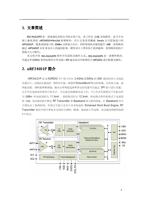
其内部结构主要由RF Transmitter和Baseband两大板块构成,在Baseband块中主要包含了射频控制、外部交互接口及芯片本身集成的Enhanced Short Burst Engine,RF Transmitter板块中则主要包含无线信号调制、解调、滤波放大等电路,其功能结构框图如图1-1所示:图1-13.nRF24l01功能及控制2.1控制引脚从编程控制的角度看,我们只需要用外部单片机控制框图1-1中右边的6个引脚,其主要功能如下:CSN:芯片的片选线,CSN为低电平芯片工作。
SCK:芯片控制的时钟线(SPI时钟)MISO:芯片控制数据线(Master input slave output)MOSI:芯片控制数据线(Master output slave input)IRQ:中断信号。
基于WiFi可移动视频监控小车的设计
基于WiFi可移动视频监控小车的设计张路;姚向国【摘要】文章设计一个基于WiFi的Arduino平台视频监控小车.文中对小车的摄像头、WiFi模块、Arduino控制板和驱动模块等硬件进行具体分析及小车系统的通信协议与下位机的软件设计,最后进行系统实施性测试.整个系统安全可靠,具有较好的实用性.【期刊名称】《南方农机》【年(卷),期】2018(049)012【总页数】2页(P88,90)【关键词】WiFi;arduino;视频回传【作者】张路;姚向国【作者单位】无锡职业技术学院物联网技术学院,江苏无锡 214121;无锡职业技术学院物联网技术学院,江苏无锡 214121【正文语种】中文【中图分类】TN92现实生活中,对于小区或工厂区的日常安全巡查依然采用人工方式,或对于个别现场,由于空间狭小或不便施工监管人员接近巡查,特别在天气情况较为恶略的情况下,人为因素容易减少巡查次数或范围,容易带来安全隐患。
目前解决此类问题通常采用现场人员或安装固定摄像头,这样依然存在人为因素或巡查死角。
当前随着载体机器人大量涌现,以及各种控制技术的成熟,使得利用WiFi组网以较低成本解决此类问题。
本文设计的WiFi视频监控小车就应用于此,通过PC端连接WiFi 远程控制小车,工作人员通过电脑端的控制,让小车行进整个区域进行视频监控,然后实时传输视频数据到 PC 端 [1]。
1 硬件系统设计该系统把Arduino控制板、WiFi模块、摄像头、电机驱动模块等集成为一体,PC 端通过WiFi模块与小车进行无线通信,利用WiFi网络发送相关的控制指令,控制小车执行相应操作。
小车摄像头采集视频数据,通过WiFi网络将采集到的数据再传递给PC控制端。
该系统就是以WiFi模块为媒介,实现上位机与下位机之间相互通信,如图1所示小车系统框架图[2]。
图1 系统框架图WiFi视频小车以带有4个12V供电的电磁干扰直流电机及轮子的底盘为车身,车身安装摄像头、WiFi模块、电机驱动模块和Arduino控制板以及用来供电的12V 的电池组。
- 1、下载文档前请自行甄别文档内容的完整性,平台不提供额外的编辑、内容补充、找答案等附加服务。
- 2、"仅部分预览"的文档,不可在线预览部分如存在完整性等问题,可反馈申请退款(可完整预览的文档不适用该条件!)。
- 3、如文档侵犯您的权益,请联系客服反馈,我们会尽快为您处理(人工客服工作时间:9:00-18:30)。
产品名称密级
LC930型WIFI模块用户手册公开
产品版本
共15页
V100
AR9331芯片2.4G无线WIFI模块用户手册
V1.0
拟制:JOHN日期:2013-04-22
审核:日期:
审核:日期:
批准:日期:
修订记录
日期修订版本描述作者2013-8-4 1.0首次建立John
深圳市灵卡技术科技有限公司
版权所有侵权必究
目录
1概述(Introduction) (4)
2特性列表(Feature List) (4)
3指标性能列表 (5)
4接口定义 (6)
5外观尺寸 (9)
6控制协议 (9)
7应用电路 (9)
AR9331芯片2.4G无线WIFI模块用户手册
关键词:
摘要:本文描述。
缩略语清单:对本文所用缩略语进行说明,要求提供每个缩略语的英文全名和中文解释Abbreviations缩略Full Spelling英文全拼Chinese Explanation中文解释ETHERNET以太网
NTSC北美地区电视标准
PAL中国大陆地区电视标准UART Universal Asynchronous通用异步接收/发送
WiFi无线局域网络通信标准
VGA图像分辨率640x480 QVGA图像分辨率320x240
GPIO通用输入输出端口
PWM脉冲宽度调制
1概述(Introduction)
LC930是深圳灵卡技术推出的低成本,较低功耗,高性能嵌入式WiFi模块。
采用高通AR9331一体化单芯片WIFI无线SOC解决方案.内部集成CPU,WIFI基带,PA,使产品体积显著减小。
LC930引出了众多功能接口,例如:串口,SPI主设备口,网口,USB口,I2S接口,GPIO口等,使得LC930可以广泛应用在无线数据传输,多媒体音视频传输,无线数据存储等应用场合。
LC930是一款基于高通Atheros ARA9331的芯片,8MB Flash,64MB DDR2的全新功能WIFI核心模块。
采用IEEE802.11n,1T1R最高可达150Mbps,具有1个USB2.0,1个高速UART串口,多个GPIO接口。
1WAN+4LAN10/100Mbps接口,方便用户灵活扩展外围接口主板,可广泛应用于各种家,商,工业嵌入式无线产品。
LC930应用广泛:
●无线WiFi音箱,无线WiFi存储,。
●智能家居,智能插座,工业控制。
●3G转WIFI,路由器。
图1LC930模块实物图和引脚
2特性列表(Feature List)
●超小体积,长宽仅40mm×28mm。
●邮票孔接口,方便安装。
●PCB天线和I-PEX接口。
● 3.3V单电源供电。
●有线+无线路由器方案
●支持802.11b/g/n协议,最高150Mbps。
●有线支持1WAN或1LAN,10M/100M自适应。
●适中的RF功率消耗。
●64MB工业级DDR2,8MB/16M SPI FLash。
●480Mbps高速USB接口。
●1路UART。
●IIS数字音频接口(192K/24bits)、IIC通讯接口、PWM、SPI master。
●丰富的GPIO。
3指标性能列表
表1模块的电气特性
电气特性
参数典型值备注
输入电压 3.3V
串口电压 3.3V
GPIO电压 3.3V
网络变压器电压 2.0V
表2无线性能参数
无线性能
1无线通讯IEEE802.11b/g/n
2频率范围 2.400~2.4835GHz
3WiFi启动时间<5s
4最大信号范围≤80m空旷距离
5802.11b输出功率11Mbps:15.5±1.5dBm 802.11g输出功率54Mbps:13.5±1.5dBm 802.11n输出功率135Mbps:11.5±1.5dBm
6802.11b接收灵敏度11M:-84dBm@8%PER 802.11g接收灵敏度54M:-73dBm@10%PER 802.11n接收灵敏度135M:-72dBm@10%PER
7频道1~11(美国,加拿大),1~13(中国,欧洲),1~14(日本)
表3其他参数
其他参数
模块天线外置天线
模块尺寸28mm*40mm
存储温度-40–70摄氏度
工作温度-20–50摄氏度
ESD耐压4KV
4接口定义
LC930预留了很多接口供用户扩展使用,主要有:
●SPI主接口;
●网络接口;
●USB接口;
●I2C接口
●GPIO接口
●I2S接口
这些接口全部采用2.0mm规格邮票口输出,如下图。
插针的具体信号如下表:
图2LC930模块接口定义
下表具体定义接口含义:
表4LC930管脚功能定义
管脚网络名信号类型说明
1GND G地
2ANTENNA天线需要主板跳线设置3GND0G地
4GND1G地
5GPIO3(SPI_CLK)I/O GPIO
6GPIO2(SPI_CS_O)I/O GPIO
7GPIO5(SPI_MISO)I/O GPIO
8GPIO4(SPI_MOSI)I/O GPIO
9GPIO17(WAN_LED)I/O GPIO
10GPIO16(LAN4_LED)I/O GPIO
11GPIO15(LAN3_LED)I/O GPIO
12GPIO14(LAN2_LED)I/O GPIO
13GPIO13(LAN1_LED)I/O GPIO
14GPIO1(USB_LED)I/O GPIO
15GPIO0(WLAN_LED)I/O GPIO
16GPIO9(UART_RX)I/O默认做调试口
17GPIO10(UART_TX)I/O默认做调试口
18GND2G地
19GND3G地
20GPIO23(SPDIF)A,I/O GPIO/数字音频输出
21GPIO20I/O I2S数据输入/GPIO
22GPIO19I/O I2S数据输出/GPIO
23GPIO18I/O I2S左右声道对齐/GPIO 24GPIO22I/O I2S时钟/GPIO
25GPIO21G I2C时钟/GPIO
26WAN_RX+A网口RX+
27WAN_RX-A网口RX-
28WAN_TX+A网口TX+
29WAN_TX-A网口TX-
30LAN3_TX+A网口RX+
31LAN3_TX-A网口RX-
32LAN3_RX+A网口TX+
33LAN3_RX-A网口TX-
34VDD_2.0V_OUTPUT Power 2.0V输出,用于网卡变压器35GPIO12I/O请留空
36GND4G地
37VDD_3.3V_IN2Power 3.3V电压输入
38VDD_3.3V_IN1Power 3.3V电压输入
39GND1G地
40USB-USBM
41USB+USBP
42GND14G地
43GPIO26(LED8)I/O GPIO
44GPIO27(LED7)I/O GPIO
45GND13I/O地
46GND12G地
47GND11G地
48GND10G地
49GND9G地
注:1、红色标记信号用于启动系统配置,外部不可驱动,不要上下拉。
5外观尺寸
图3LC930尺寸标注
6控制协议
7应用电路。
