安讯士摄像机安装调试指南V1
AXISM1054网络摄像机安装指引-AxisCommunications
该产品符合 EN 55024 办公和商用环境抗干 扰要求。 澳大利亚/新西兰 该数字设备 符合 AS/NZS CISPR 22 B 类限制 的射频辐射要求。产品应当使用正确接地的屏 蔽网线 (STP) 进行连接。
安全
该产品符合 IEC/EN 60950-1信息技术设备安 全标准。如果连接线在室外布置,本产品必须 通过屏蔽网线(STP)或其它方法正确接地。 本产品使用的电源应该满足 IEC/EN/UL 60950-1的安全极低电压 (SELV) 及有限电源 (LPS) 的要求。
AXIS M1054 网络摄像机 安装指南
法律考虑事项 视频和音频监控可能会受法律管制,各个国 家/地区的法律会有所不同。如将本产品用于 监控目的,需要先检查是否符合你所在区域 内的法律规定。 本产品包括一个(1)H.264解码器许可和一个 (1)AAC 解码器许可。要购买更多许可,请 与您的经销商联系。
• 重新定向或重新定位接收天线。 • 增加设备与接收器的间隔距离。 • 将设备连接到不与接收器相连的回路的
插座上。
• 请咨询经销商或有经验的收音机/电视机
技术人员。 产品应当使用正确接地的屏蔽网线 (STP) 进 行连接。 加拿大 本数字设备符合 CAN ICES-3 (B 类)要 求。本产品必须连接一个正确接地的屏蔽网线 (STP)。 Cet appareil numérique est conforme à la norme CAN NMB-3 (classe B).Le produit doit être connecté à l'aide d'un câble réseau blindé (STP) qui est correctement mis à la terre. 欧洲 该数字设备符合 EN 55022 B 类限制的射频 辐射要求。产品应当使用正确接地的屏蔽网 线 (STP) 进行连接。 该产品符合 EN 61000-6-1 住宅、商用和轻工 业环境的抗扰度要求。 该产品符合 EN 61000-6-2 工业环境的抗扰 度要求。
监控摄像机基本使用方法和安装操作本月修正简版

监控摄像机基本使用方法和安装操作监控摄像机基本使用方法和安装操作监控摄像机是一种广泛应用于各种场合的安全设备,它可以通过录像或实时监视的方式提供监控和防护。
本文将介绍监控摄像机的基本使用方法和安装操作。
一、监控摄像机的基本使用方法1. 开启监控摄像机要开始使用监控摄像机,需要将其连接到电源并打开电源开关。
通常,摄像机会附带一个电源适配器,您只需将其插入适配器插座,并将另一端插入摄像机的电源接口。
一旦接通电源,摄像机就会自动启动。
2. 连接监控摄像机监控摄像机通常支持有线和无线两种连接方式。
如果您选择有线连接,只需将摄像机的网线插入摄像机的网络接口,然后将另一端插入路由器或网络交换机的网络接口。
如果您选择无线连接,需要将摄像机与无线路由器进行配对,具体的配对方式可以参考您所使用摄像机的说明书。
3. 设置监控摄像机一旦摄像机成功连接到网络,您可以通过访问摄像机的IP地质或域名来配置和管理摄像机。
通常,您可以使用方式、电脑或平板电脑上的相关应用或软件来进行配置。
登录后,您可以设置摄像机的分辨率、图像质量、录像模式、移动侦测等功能。
4. 进行实时监控和录像配置完成后,您可以通过相关应用或软件来进行实时监控。
只需打开应用或软件,并选择您要监控的摄像机,您就可以在设备上查看实时画面。
如果您需要录像,大多数监控摄像机都支持定时、移动侦测等录像模式,您可以根据需要进行设置。
二、监控摄像机的安装操作1. 确定安装位置在安装监控摄像机之前,您需要确定合适的安装位置。
,您需要考虑监控范围和监控目的,选择一个合适的覆盖范围。
,您需要确保安装位置可以提供稳定的支撑,以避免摄像机晃动或移位。
2. 安装支架和摄像机安装摄像机之前,您需要安装支架。
通常,支架会附带摄像机,并配有安装螺丝。
,您需要使用螺丝将支架固定在合适的位置上,然后将摄像机与支架连接起来。
确保连接牢固并定位准确。
3. 连接电源和网络安装完成后,您需要将摄像机连接到电源和网络。
Hikvision 手机视频录像机快速上手指南及安装指南说明书

Mobile Video RecorderQuick Start GuideLegal Information©2022 Hangzhou Hikvision Digital Technology Co., Ltd. All rights reserved.About this ManualThe Manual includes instructions for using and managing the Product. Pictures, charts, images and all other information hereinafter are for description and explanation only. The information contained in the Manual is subject to change, without notice, due to firmware updates or other reasons. Please find the latest version of this Manual at the Hikvision website (https:///).Please use this Manual with the guidance and assistance of professionals trained in supporting the Product.Trademarksand other Hikvision’s trademarks and logos are the properties of Hikvision in various jurisdicti ons. Other trademarks and logos mentioned are the properties of their respective owners.DisclaimerTO THE MAXIMUM EXTENT PERMITTED BY APPLICABLE LAW, THIS MANUAL AND THE PRODUCT DESCRIBED, WITH ITS HARDWARE, SOFTWARE AND FIRMWARE, ARE PROVIDED “AS IS” AND “WITH ALL FAULTS AND ERRORS”. HIKVISION MAKES NO WARRANTIES, EXPRESS OR IMPLIED, INCLUDING WITHOUT LIMITATION, MERCHANTABILITY, SATISFACTORY QUALITY, OR FITNESS FOR A PARTICULAR PURPOSE. THE USE OF THE PRODUCT BY YOU IS AT YOUR OWN RISK. IN NO EVENT WILL HIKVISION BE LIABLE TO YOU FOR ANY SPECIAL, CONSEQUENTIAL, INCIDENTAL, OR INDIRECT DAMAGES, INCLUDING, AMONG OTHERS, DAMAGES FOR LOSS OF BUSINESS PROFITS, BUSINESS INTERRUPTION, OR LOSS OF DATA, CORRUPTION OF SYSTEMS, OR LOSS OF DOCUMENTATION, WHETHER BASED ON BREACH OF CONTRACT, TORT (INCLUDING NEGLIGENCE), PRODUCT LIABILITY, OR OTHERWISE, IN CONNECTION WITH THE USE OF THE PRODUCT, EVEN IF HIKVISION HAS BEEN ADVISED OF THE POSSIBILITY OF SUCH DAMAGES OR LOSS.YOU ACKNOWLEDGE THAT THE NATURE OF THE INTERNET PROVIDES FOR INHERENT SECURITY RISKS, AND HIKVISION SHALL NOT TAKE ANY RESPONSIBILITIES FOR ABNORMAL OPERATION, PRIVACY LEAKAGE OR OTHER DAMAGES RESULTING FROM CYBER-ATTACK, HACKER ATTACK, VIRUS INFECTION, OR OTHER INTERNET SECURITY RISKS; HOWEVER, HIKVISION WILL PROVIDE TIMELY TECHNICAL SUPPORT IF REQUIRED.YOU AGREE TO USE THIS PRODUCT IN COMPLIANCE WITH ALL APPLICABLE LAWS, AND YOU ARE SOLELY RESPONSIBLE FOR ENSURING THAT YOUR USE CONFORMS TO THE APPLICABLE LAW. ESPECIALLY, YOU ARE RESPONSIBLE, FOR USING THIS PRODUCT IN A MANNER THAT DOES NOT INFRINGE ON THE RIGHTS OF THIRD PARTIES, INCLUDING WITHOUT LIMITATION, RIGHTS OF PUBLICITY, INTELLECTUAL PROPERTY RIGHTS, OR DATA PROTECTION AND OTHER PRIVACY RIGHTS. YOU SHALL NOT USE THIS PRODUCT FOR ANY PROHIBITED END-USES, INCLUDING THE DEVELOPMENT OR PRODUCTION OF WEAPONS OF MASS DESTRUCTION, THE DEVELOPMENT OR PRODUCTION OF CHEMICAL OR BIOLOGICAL WEAPONS, ANY ACTIVITIES IN THE CONTEXT RELATED TO ANY NUCLEAR EXPLOSIVE OR UNSAFE NUCLEAR FUEL-CYCLE, OR IN SUPPORT OF HUMAN RIGHTS ABUSES.IN THE EVENT OF ANY CONFLICTS BETWEEN THIS MANUAL AND THE APPLICABLE LAW, THE LATTER PREVAILS.Regulatory InformationFCC InformationPlease take attention that changes or modification not expressly approved by the party responsible for compliance could void the user’s authority to operate the equipment.FCC ComplianceThis equipment has been tested and found to comply with the limits for a Class A digital device, pursuant to part 15 of the FCC Rules. These limits are designed to provide reasonable protection against harmful interference when the equipment is operated in a commercial environment. This equipment generates, uses, and can radiate radio frequency energy and, if not installed and used in accordance with the instruction manual, may cause harmful interference to radio communications. Operation of this equipment in a residential area is likely to cause harmful interference in which case the user will be required to correct the interference at his own expense.FCC ConditionsThis device complies with part 15 of the FCC Rules. Operation is subject to the following two conditions:1.This device may not cause harmful interference.2.This device must accept any interference received, including interference that may causeundesired operation.EU Conformity StatementThis product and - if applicable - the supplied accessories too are marked with "CE" andcomply therefore with the applicable harmonized European standards listed under the EMC Directive 2014/30/EU, the LVD Directive 2014/35/EU, the RoHS Directive 2011/65/EU, RE Directive 2014/53/EU.2012/19/EU (WEEE directive): Products marked with this symbol cannot be disposed of as unsorted municipal waste in the European Union. For proper recycling, return this product to your local supplier upon the purchase of equivalent new equipment, or dispose of it at designated collection points. For more information see: 2006/66/EC (battery directive): This product contains a battery that cannot be disposedof as unsorted municipal waste in the European Union. See the product documentation for specific battery information. The battery is marked with this symbol, which may include lettering to indicate cadmium (Cd), lead (Pb), or mercury (Hg). For proper recycling, return the battery to your supplier or to a designated collection point. For more information see: Industry Canada ICES-003 ComplianceThis device meets the CAN ICES-3 (A)/NMB-3(A) standards requirements.Symbol ConventionsTABLE OF CONTENTSChapter 1 Panel Introduction (1)Front Panel (1)Rear Panel (2)Chapter 2 Installation and Connections (4)Environment (4)Install HDD (4)Install SIM Card (8)Install SD Card (9)Install Antenna (10)Chapter 3 Device Wiring (12)Power Cord Wiring (12)3.1.1 Shutdown Delay (12)3.1.2 Scheduled Shutdown (13)Alarm Input/Output Connection (14)3.2.1 Alarm Input Connection (14)3.2.2 Alarm Output Connection (14)Sensor-in Wiring (15)Power-on (15)Chapter 1 Panel Introduction Front PanelFront PanelNo. Name Description1 Dummy HDD Two HDDs can be installed.2 Network interface 10M/100M/1000M RJ45 Ethernet interface.3 USB 3.0 USB 3.0 interface.4 PWR indicator●Solid green: Device is powered on.●Solid red: Device is standby.RDY indicator ●Solid green: Device starts up normally. REC indicator●Recording indicator.●Solid green: Device is recording normally. GNSS indicator●Unlit: Positioning module is abnormal.●Solid green: Device is positioning.●Flashing green: Positioning succeeded. ANT indicator●Unlit: Dialing module is abnormal.●Solid green: Device is dialing.●Flashing green: Dialing up succeeded. ALM indicator Red: Alarm occurs.Rear PanelRear Panel5IR receiver IR receiver for remote control. 6Dummy HDD lock Lock/unlock the dummy HDD. 7 SD card slot Slot for SD card.No. NameDescription 1RS-485 interface RS-485 interface for connecting devices like speed dome. 2RS-232 interface RS232-1 is for debugging. 3RS-232 interface RS232-2 is for connecting external devices. 4EXT.DEV RS-485 communication interface, two-way audio interface, and CVBS video output 5VGA VGA video output interface 6 USB interface USB interface of 5-pin aviation plug.Chapter 2 Installation and ConnectionsEnvironmentTo ensure the device can ventilate well, find a position with enough space. Recommended installation space is shown in Figure 2-1.Recommended Installation SpaceInstall HDDBefore You Start:Prepare the tools and components for installation:●Factory recommended 2.5-inch HDD.●Antistatic gloves.●Key to dummy HDD (delivered with device).●Cross screwdriver.●Screws (delivered with device).ToolsPurpose:Perform the following steps to install the HDD on the device. Figures in following steps are only for reference.Wear antistatic gloves.Insert the key and turn counterclockwise to unlock dummy HDD.Unfasten the two screws of dummy HDD and pull dummy HDD out of device.Dummy HDDUnfasten ScrewsPull Dummy HDD outUse cross screwdriver to loosen the two screws and remove them, and then take the dummy HDD apart.Place the first HDD into the dummy HDD, with the PCB facing down.Place HDDPush the HDD along the direction shown in Figure 2-6 to connect HDD with socket of dummyHDD.Push HDDUse four sunk screws to fix HDD with dummy HDD.Fix HDDRepeat step 4 to 6 to install the secondary HDD in the other socket of dummy HDD.Install the Other HDDReassemble the dummy HDD.Reassemble Dummy HDDPlug the dummy HDD back to the device and then tighten the screws clockwise.Turn the key clockwise to lock dummy HDD.Install SIM CardPurpose:Pluggable 4G/5G wireless communication module is designed for the device and you should install the SIM card to realize the wireless communication function.Before You StartPrepare the tools and components for installation:●SIM card●WrenchPhillips ScrewdriverWear antistatic gloves.Use wrench to unfasten and remove the two screws fixing the 4G/5G and Wi-Fi module.Unfasten ScrewsPull out the 4G/5G and Wi-Fi module. Press the yellow button on the 4G/5G slot and then pull the SIM card tray out.Place the SIM card on SIM card tray with the metal side facing upwards.Insert the SIM card tray back to SIM card slot.Install the 4G/5G module back to the device and tighten the set screw.Install SD CardBefore You StartPrepare the tools and components for installation:● Key to dummy HDD (delivered with device)● SD cardToolsWear antistatic gloves.Insert the key and turn counterclockwise to unlock dummy HDD.Unfasten the two screws of dummy HDD and pull dummy HDD out of device.Unfasten ScrewsDummy HDDUnfasten ScrewsOpen the cover of SD card slot.Insert SD card into SD card slot with gold contacts facing down till you hear a click.Plug the dummy HDD back to the device, close the cover of SD card slot, and then tighten the screws clockwise.Turn the key clockwise to lock dummy HDD.Install AntennaThis section is only applicable to the device supporting 4G/5G and Wi-Fi.Connect antennas to corresponding antenna interfaces.Antenna InterfaceInterface Corresponding AntennaM-ANT/Main 4G/5G antennaAUX Aux Wi-Fi antennaWIFI/Main Wi-Fi antennaGNSS/Positioning antennaPlace antenna vertically with its signal receiving end facing upward.If the cable is too long, you can roll them up to prevent signal receiving from being affected.Install 4G/5G antenna in car windshield, seat backrest, or other non-metallic objects. Keep away from metal objects for at least 50 cm.Vertically install positioning antenna on the automobile roof with no shelter.Install Positioning Antenna on Automobile RoofFollow the instructions below in case that you need to install positioning antenna inside your automobile.1)Install antenna on platform under the front windshield.Install Positioning Antenna Inside Automobile2)Fix antenna with neutral silica gel.3)When adjusting the antenna position, ensure that at least 4 satellites have a signalstrength above 35 dB. You can go to Configuration > Vehicle > Position Settings > Location Status to view positioning signal status.Chapter 3 Device WiringPower Cord WiringIn order to ensure the safety of your automobile and device, a fuse is required for wiring of automobile power and device power.Do not connect the power cord to the device before all the cables are connected.Purpose:The device starts up when your automobile ignites and shuts down after automobile is off. Automobile ignition startup and shutdown are realized by automobile positive pole ignition switch (providing high level signal when the switch closes). The wire connection of the device varies with the automobile ignition models.Ignition switch is connected to the positive pole of +12/24 VDC of automobile batteries. Make sure that the connection is correct, and then perform the following steps:Connect the DC IN + of the device to the positive pole of automobile batteries, jumping over the switch of normal automobile power.Connect the DC IN - of the device to the negative pole of automobile batteries.Connect the ACC of the device to the automobile ignition switch.Place the fuse into the fuse holder.What to do next: For detailed time settings of time-delay shutdown, see the Chapter “Configure Delayed Shutdown” in user manual.Install Fuse for Two Types of Power SupplyACC DC IN +-Automobile Ignition SwitchDeviceAutomobileBattery Automobile Power System Wiring of DevicePoint of Connection Positive PoleNegative PoleAutomobile Power SwitchShutdown Delay● Please contact the automobile manufacturer for the connection information of ignitionswitch.● The automobile ignition switch, also called car key, controls the startup and shutdown ofyour automobile . Most of automobiles adopt positive pole ignition switch currently.● The normal automobile power refers to the main power of the automobile power supplysystem. After the automobile is off, the normal automobile power still provides direct-current source for the other devices inside and generally a main switch is used to turnon/off it.Connect the DC IN + and KEY + of the device to the positive pole of automobile batteries. Connect the DC IN - and KEY - of the device to the negative pole of automobile batteries. Place the fuse into the fuse holder.What to do next: For detailed time settings of time-delay shutdown, see the Chapter “Enable Scheduled Startup/Shutdown” in user manual.Install Fuse for Power SupplyACC DC IN+-DeviceAutomobileBattery Automobile Power SwitchAutomobile Power System Wiring of DevicePoint of Connection Negative PolePositive PoleScheduled Shutdown Alarm Input/Output ConnectionThe device adopts the high/low-level electrical signals triggering (high level: 6 to 36 VDC; low level: 0 to 5 VDC) to realize alarm input. And in order to avoid error report caused by voltage fluctuation, no alarm will be triggered by voltage ranging of 5 to 6 VDC.Alarm 1IO Alarm 2Alarm 3Alarm 4121516Alarm Input Connection Follow the figure bellow to wire alarm output.n and n# are a pair of alarm output. You can connect them with a relay alarm device. When the voltage of connected alarm device exceeds the valid alarm output range, you need to connect a relay to protect alarm output.RelayOutput nn#Load GND Power Output JQC-3FG Relay (10 A/250 VAC)~ 220 VAC NeutralLive Relay Output n#n Alarm Powered by Direct Current Alarm Powered by Alternating CurrentAlarm Output Connection Sensor-in WiringConnect the delivered extension cable to I/O interface.Connect the automobile braking, reversing, left-turn, and right-turn signals to sensor-in interface.IOBrakingReversing121516Left-turn Right-turnSensor-in Wiring Power-onThe indicator types vary with different models. Here the most comprehensive indicators are introduced.Connect the device to power supply after all the installations above are finished. You can view the indicators to get knowledge of the device status. For details, see descriptions in Table 1-1UD 16。
摄像机安装调试的规范要求和作业指导书
摄像机安装调试的规范要求和作业指导书1.目的本作业指导书用于指导现场安装调试摄像机。
(1)指导如何确定安装位置/高度/朝向/角度以得到满足规范要求的图像。
(2)指导安装镜头并调整摄像机和镜头的状态,使摄像机图像达到预期的效果。
(3)不包括使用立竿支架护罩等设施和相应的工具完成摄像机固定的工作。
(4)不包括使用软件连接摄像机观察到视频图像的具体方法,请阅读产品说明书。
2.范围1.适用于本公司技术支持人员和客户单位工程安装调试人员。
2.适用于数字摄像机。
3.安装调试工具1.螺丝刀,转接环,镜头纸,手套。
2.笔记本电脑,网络线缆。
3.工程宝便携式调试仪器。
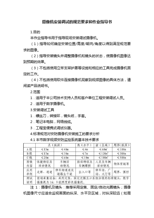
4.标准规范对安防摄像机安装施工的要求分析4.1本市数字视频安防监控系统基本技术要求注1:摄像机及镜头:推荐采用定焦、固定/自动光圈镜头;摄像机图像尺寸应适合监视画面的纵深、水平及区域,对纵深较远(如周界)的监视画面应选用4:3的图像尺寸。
注2:布点设计室外以1080P为主室内视实际情况而定。
数字视频安防监控系统的布控应根据所监视区域的点(纵深)、线(水平)、面(区域)进行分别设计,应充分考虑数字摄像机较模拟摄像机对监视环境适应性不同的优劣和特征。
同一数字视频监控系统的清晰度可根据所选用摄像机清晰度的不同而允许存在多种分级。
用于特征性场合摄像机(如:电梯等),带云台变焦镜头摄像机可采用模拟摄像机,系统组成方式,可沿用原有模拟摄像机+视频电缆(控制和电缆)+硬盘录像设备等方式独立搭建,系统指标应不低于270线;重要场合摄像机(除小区楼栋出入口外)的选型应保证系统清晰度指标不低于600线,网络型摄像机应安装存储介质,且不宜采用POE供电方式。
电梯轿厢采用模拟摄像机的,应安装在电梯轿箱顶部、电梯控制面板的上方,应配置电梯楼层信号叠加显示器;采用数字摄像机的,应具有抗逆光功能,应安装在电梯轿箱顶部、电梯控制面板的对角处。
网络型摄像机应具有网络中断、设备故障、报警状态的本地视(音)频信息存储功能,存储图像的性能指标应符合《本市视频安防监控用彩色数字摄像机技术规范》4.4条的要求。
AXIS P1264网络针孔摄像机说明书
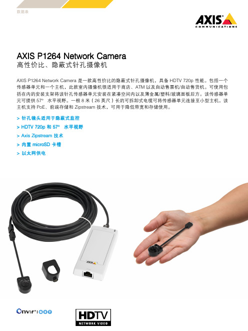
表数据AXIS P1264Network Camera高性价比、隐蔽式针孔摄像机AXIS P1264Network Camera是一款高性价比的隐蔽式针孔摄像机,具备HDTV720p性能。
包括一个传感器单元和一个主机,此款室内摄像机很适用于商店、ATM以及自动售票机/自动售货机。
可使用包括在内的安装支架将该针孔传感器单元安装在紧凑空间内以及薄金属/塑料/玻璃面板后方。
该传感器单元可提供57°水平视野。
一根8米(26英尺)长的可拆卸式电缆可将传感器单元连接至小型主机。
该主机支持PoE、前端存储和Zipstream技术,可用于降低带宽和存储使用。
>针孔镜头适用于隐蔽式监控>HDTV720p和57°水平视野>Axis Zipstream技术>内置microSD卡槽>以太网供电AXIS P1264Network Camera 摄像机图像传感器1/4''(有效)逐行扫描RGB CMOS镜头固定光圈、固定焦距、针孔3.7毫米,F2.5水平视野:57°垂直视野:31°最低照度颜色:0.5lux快门时间1/24500s至1/6s视频视频压缩H.264(MPEG-4Part10/AVC)Baseline、Main和HighProfileMotion JPEG分辨率1280x720至480x270帧速率25/30fps(50/60Hz)视频流提供多个可单独配置的H.264和Motion JPEG格式的视频流采用H.264格式的Axis Zipstream技术可控制的帧速和带宽VBR/ABR/MBR H.264图像设置压缩、颜色、亮度、锐度、对比度、白平衡、曝光值、曝光控制、曝光区域、局部对比度、旋转、走廊模式、WDR、文本和图像叠加、隐私遮罩、图像成像网络安全密码保护、IP地址过滤、HTTPS a加密、IEEE802.1X(EAP-TLS)a网络访问控制、摘要式身份验证、用户访问日志、集中式证书管理、强力延迟保护、签名固件支持的协议IPv4、IPv6USGv6、HTTP、HTTPS a、SSL/TLS a、QoS Layer3DiffServ、FTP、CIFS/SMB、SMTP、Bonjour、UPnP TM、SNMPv1/v2c/v3(MIB-II)、DNS、DynDNS、NTP、RTSP、RTP、SFTP、TCP、UDP、IGMPv1/v2/v3、RTCP、ICMP、DHCP、ARP、SOCKS、SSH、LLDP、MQTT v3.1.1系统集成应用程序编程接口用于进行软件集成的开放API,包括VAPIX®和AXIS Camera Application Platform(ACAP);规格请参见一键云连接ONVIF®Profile G、ONVIF®Profile S和ONVIF®Profile T,规格请参见事件触发分析前端存储事件事件动作文件上传:电子邮件、FTP、HTTP、HTTPS、网络共享通知:电子邮件、HTTP、HTTPS和TCP报警前和报警后视频缓冲发送SNMP陷阱、WDR模式内置安装帮助像素计算器数据流事件数据分析应用随附AXIS Motion Guard、AXIS Fence Guard、AXIS Loitering Guard、AXIS视频移动侦测支持AXIS Cross Line Detection支持AXIS Camera Application Platform,能够安装第三方应用,请参见/acap常规外壳AXIS P12Mk II Main UnitUnit::钢和塑料AXIS F1004Pinhole Sensor UnitUnit::金属外壳(铝)存储器512MB RAM,256MB闪存电源以太网供电IEEE802.3af/802.3at1型2类最大4.0W,标准2.5W接口用于10BASE-T/100BASE-TX PoE的内孔RJ45用于传感器单元的RJ12存储支持microSD/microSDHC/microSDXC卡和加密录制到网络附加存储(NAS)有关SD卡和NAS的建议,请参见工作条件-20°C至50°C(-4°F至122°F)湿度10-85%RH(非冷凝)存放条件-40°C至65°C(-40°F至149°F)湿度5-95%RH(非冷凝)认证EMCEN55022B类、FCC第15部分B子部分B类、ICES-003B类、VCCI B类安全IEC/EN/UL60950-1、IS13252环境IEC60068-2-1、IEC60068-2-2、IEC60068-2-6、IEC60068-2-14、IEC60068-2-27网络NIST SP500-267尺寸AXIS P12Mk II Main UnitUnit::16x46x109毫米(0.6x1.8x4.3英寸)AXIS F1004Pinhole Sensor UnitUnit::27x20x18毫米(1.1x0.8x0.7英寸)传感器单元电缆:8米(26英尺)重量AXIS P12Mk II Main UnitUnit::72克(0.16磅)AXIS F1004Pinhole Sensor UnitUnit::14克(0.03磅)传感器单元电缆:128克(0.28磅)所含附件安装指南、Windows®解码器单用户许可证AXIS F8206Pinhole Mounting Bracket8米(26英尺)黑色电缆可选附件AXIS T812015W Midspan1-portAXIS T8129PoE ExtenderNetwork cable coupler indoor slimAXIS Surveillance CardsAXIS F7315Cable White15mAXIS F8204Mounting BandAXIS F9201Black Height Strip HousingAXIS F9201Silver Height Strip Housing有关更多附件的信息,请参见视频管理软件AXIS Companion、AXIS Camera Station、Axis应用开发合作伙伴的视频管理软件可在/vms上获得质保有关5年保修的信息,请参见/warrantya.本产品包括由OpenSSL Project开发的用于OpenSSL工具包的软件(/)以及由Eric Young(*****************)编写的加密软件。
安迅宝 NVR4 8CH 网络硬盘录像机 快速操作指南说明书
NVR 硬盘录像机1 声明非常感谢您购买网络硬盘录像机产品,如果您有什么疑问或需要请随时联系我们。
本手册适用的产品型号:MINI 4/8CH2 注意事项9路以上NVR必须接入千兆交换机,否则会出现丢失视频或卡顿的现象;局域网内所有网络设备的IP地址不能冲突;网关需要与IP地址匹配,设置正确。
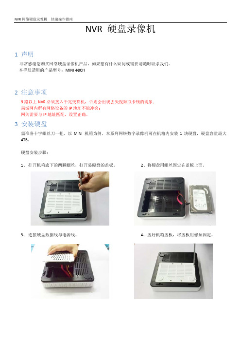
3 安装硬盘需准备十字螺丝刀一把。
以MINI 机箱为例,本系列网络数字录像机可在机箱内安装1块硬盘,硬盘容量最大4TB。
硬盘安装步骤:1、拧开机箱底下的两颗螺丝,打开装硬盘的盖板。
2、将硬盘用螺丝固定在盖板上面。
3、连接硬盘数据线与电源线。
4、盖好机箱盖板,将盖板用螺丝固定。
4 后面板接口说明MINI 4/8CH5 主机操作5.1 开机插上电源线,按下后尾板电源开关,NVR 开机。
开机完成后视频输出默认为多画面输出模式,若开机启动时间在录像设定时间内,系统将自动启动定时录像功能。
注意:请使用与网络数字录像机配套提供的电源,不得使用其它类型或品牌的电源代替原配电源。
5.2 登陆系统正常开机后,会出现开机向导画面。
管理员默认密码为:123456 鼠标单击“下一步”进入到设置向导5.3 设置向导此页面可以设置设备名称、系统语言、系统时间 等;设置完成后鼠标单击“下一步”进入到向导网络 设置;HDMI 高清接口USB 接口电源输入5.4 网络设置进入网络参数界面,设置网络参数,设置好NVR 的IP 地址、子网掩码、网关等。
可以通过用局域网内的PC 主机运行命令ping 命令去ping NVR 的IP 检测NVR是否已经连接进局域网。
注意:IP 地址存在冲突风险,请正确设置网关。
否刚将导致NVR 工作不正常,请确保局域网内所 有网络设备IP 地址的唯一性。
单击“完成”按钮进入到NVR 主界面。
5.5 关机主界面点击下方状态栏 “关闭系统”按钮, 1. 注销:注销当前用户名,锁定NVR ; 2. 关机:设备自动关机; 3. 重启:设备自动重启;(提示:关机时建议使用 此方式,以避免意外断电时对设备造成的损害)。
Hikvision 移动网络摄像头安装指南说明书

·Mobile Network CameraInstallation GuideLegal Information©2022 Hangzhou Hikvision Digital Technology Co., Ltd. All rights reserved.About this ManualThe Manual includes instructions for using and managing the Product. Pictures, charts, images and all other information hereinafter are for description and explanation only. The information contained in the Manual is subject to change, without notice, due to firmware updates or other reasons. Please find the latest version of this Manual at the Hikvision website (https:///).Please use this Manual with the guidance and assistance of professionals trained in supporting the Product.Trademarksand other Hikvision’s trademarks and logos are the properties of Hikvision in various jurisdictions. Other trademarks and logos mentioned are the properties of their respective owners.DisclaimerTO THE MAXIMUM EXTENT PERMITTED BY APPLICABLE LAW, THIS MANUAL AND THE PRODUCT DESCRIBED, WITH ITS HARDWARE, SOFTWARE AND FIRMWARE, ARE PROVIDED “AS IS” AND “WITH ALL FAULTS AND ERRORS”. HIKVISION MAKES NO WARRANTIES, EXPRESS OR IMPLIED, INCLUDING WITHOUT LIMITATION, MERCHANTABILITY, SATISFACTORY QUALITY, OR FITNESS FOR A PARTICULAR PURPOSE. THE USE OF THE PRODUCT BY YOU IS AT YOUR OWN RISK. IN NO EVENT WILL HIKVISION BE LIABLE TO YOU FOR ANY SPECIAL, CONSEQUENTIAL, INCIDENTAL, OR INDIRECT DAMAGES, INCLUDING, AMONG OTHERS, DAMAGES FOR LOSS OF BUSINESS PROFITS, BUSINESS INTERRUPTION, OR LOSS OF DATA, CORRUPTION OF SYSTEMS, OR LOSS OF DOCUMENTATION, WHETHER BASED ON BREACH OF CONTRACT, TORT (INCLUDING NEGLIGENCE), PRODUCT LIABILITY, OR OTHERWISE, IN CONNECTION WITH THE USE OF THE PRODUCT, EVEN IF HIKVISION HAS BEEN ADVISED OF THE POSSIBILITY OF SUCH DAMAGES OR LOSS.YOU ACKNOWLEDGE THAT THE NATURE OF THE INTERNET PROVIDES FOR INHERENT SECURITY RISKS, AND HIKVISION SHALL NOT TAKE ANY RESPONSIBILITIES FOR ABNORMAL OPERATION, PRIVACY LEAKAGE OR OTHER DAMAGES RESULTING FROM CYBER-ATTACK, HACKER ATTACK, VIRUS INFECTION, OR OTHER INTERNET SECURITY RISKS; HOWEVER, HIKVISION WILL PROVIDE TIMELY TECHNICAL SUPPORT IF REQUIRED.YOU AGREE TO USE THIS PRODUCT IN COMPLIANCE WITH ALL APPLICABLE LAWS, AND YOU ARE SOLELY RESPONSIBLE FOR ENSURING THAT YOUR USE CONFORMS TO THE APPLICABLE LAW. ESPECIALLY, YOU ARE RESPONSIBLE, FOR USING THIS PRODUCT IN A MANNER THAT DOES NOT INFRINGE ON THE RIGHTS OF THIRD PARTIES, INCLUDING WITHOUT LIMITATION, RIGHTS OF PUBLICITY, INTELLECTUAL PROPERTY RIGHTS, OR DATA PROTECTION AND OTHER PRIVACY RIGHTS. YOU SHALL NOT USE THIS PRODUCT FOR ANY PROHIBITED END-USES, INCLUDING THE DEVELOPMENT OR PRODUCTION OF WEAPONS OF MASS DESTRUCTION, THE DEVELOPMENT OR PRODUCTION OF CHEMICAL OR BIOLOGICAL WEAPONS, ANY ACTIVITIES IN THE CONTEXT RELATED TO ANY NUCLEAR EXPLOSIVE OR UNSAFE NUCLEAR FUEL-CYCLE, OR IN SUPPORT OF HUMAN RIGHTS ABUSES.IN THE EVENT OF ANY CONFLICTS BETWEEN THIS MANUAL AND THE APPLICABLE LAW, THE LATTER PREVAILS.Regulatory InformationFCC InformationPlease take attention that changes or modification not expressly approved by the party responsible for compliance could void the user’s authority to operate the equipment.FCC ComplianceThis equipment has been tested and found to comply with the limits for a Class A digital device, pursuant to part 15 of the FCC Rules. These limits are designed to provide reasonable protection against harmful interference when the equipment is operated in a commercial environment. This equipment generates, uses, and can radiate radio frequency energy and, if not installed and used in accordance with the instruction manual, may cause harmful interference to radio communications. Operation of this equipment in a residential area is likely to cause harmful interference in which case the user will be required to correct the interference at his own expense.FCC ConditionsThis device complies with part 15 of the FCC Rules. Operation is subject to the following two conditions:1.This device may not cause harmful interference.2.This device must accept any interference received, including interference that may causeundesired operation.EU Conformity StatementThis product and - if applicable - the supplied accessories too are marked with "CE" andcomply therefore with the applicable harmonized European standards listed under the EMC Directive 2014/30/EU, the LVD Directive 2014/35/EU, the RoHS Directive 2011/65/EU.2012/19/EU (WEEE directive): Products marked with this symbol cannot be disposed of as unsorted municipal waste in the European Union. For proper recycling, return this product to your local supplier upon the purchase of equivalent new equipment, or dispose of it at designated collection points. For more information see: 2006/66/EC (battery directive): This product contains a battery that cannot be disposedof as unsorted municipal waste in the European Union. See the product documentation for specific battery information. The battery is marked with this symbol, which may include lettering to indicate cadmium (Cd), lead (Pb), or mercury (Hg). For proper recycling, return the battery to your supplier or to a designated collection point. For more information see: Industry Canada ICES-003 ComplianceThis device meets the CAN ICES-3 (A)/NMB-3(A) standards requirements.Applicable ModelsSymbol ConventionsSafety Instructions●Proper configuration of all passwords and other security settings is the responsibility of theinstaller and/or end-user.●In the use of the product, you must be in strict compliance with the electrical safety Inputvoltage should meet limited power source or PS2 requirements regulations of the nation and region. Please refer to technical specifications for detailed information.●Input voltage should meet limited power source or PS2 requirements according to theIEC60950-1 or IEC 62368-1 standard. Please refer to technical specifications for detailedinformation.●Do not connect several devices to one power adapter as adapter overload may cause over-heating or a fire hazard.●Please make sure that the plug is firmly connected to the power socket.●If smoke, odor or noise rise from the device, turn off the power at once and unplug the powercable, and then please contact the service center.TABLE OF CONTENTSChapter 1 Packing List and Cable Description (1)Packing List (1)Cable Description (3)Chapter 2 Installation (4)Installation Requirements (4)2.1.1 Installation Position Requirements (4)2.1.2 Installation Surface Requirements (4)2.1.3 Water Proof Requirements (4)Vertical Installation (4)2.2.1 Vertical Installation Method 1 (4)2.2.2 Vertical Installation Method 2 (7)Horizontal Installation (11)Chapter 3 Angle Adjustment (15)Adjust With Wrench (15)Adjust the Body of the Camera (16)Chapter 1 Packing List and Cable DescriptionBefore You BeginBefore unboxing, check if the package is intact. Refer to the list to make sure that all the assembly parts are included. The 3 types of packing lists of the mobile network camera is shown below.Packing ListThere are 3 type of cable available, differing on their support for power, alarm and internet interface. Please choose according to your actual need.Packing List of Type I CameraNoPicture Name Number 1Camera 12Wrench 13ST4.8×25 Screws 1 4QSG 1 5Tape 3 6Water Proof Suit(Only Available forRJ45 Cable)1Packing List of Type II CameraNoPicture Name Number 1Camera 12Wrench 13ST4.8×25 Screws 1 4QSG15Tape 3NoPicture Name Number 1Camera 12Wrench 13ST4.8×25 Screws 14QSG 1 5Tape 3Cable DescriptionThere are 3 types of cables for the network camera, as shown in the following figures. Please refer to the relevant instructions according to the physical equipment.Rj45 Cable4 Core Cable6 Core Cable ● Power Interface: the camera supports 9V-36V power supply. Please connect the positive and negative poles of the power supply correctly.● Internet Interface: network signal output.● Alarm Interface: support alarm input and output.Chapter 2 InstallationInstallation RequirementsBefore you beginPuncture a hole on the body of the vehicle for the cable of the camera to go through. Match the sheet metal fixed support with the hole when installing the camera.The camera can be installed both horizontally and vertically, though the later is preferred. Typically, horizontal installation is recommended for the police vehicle, and the vertical installation is recommended for school bus and ambulance.To install the camera vertically, two requirements should be met for the best capture performance and the ease of installation:●The height of installation should be between 1-1.6 m●The surface of installation should be vertical to the ground.When both requirements can be met, refer to 2.2.1 Vertical Installation Method 1. If not and camera is to be installed on a tilted surface, refer to 2.2.2 Vertical Installation Method 2. On the tilted surface, the camera requires further calibration of its angle.For the stability of the camera, two further requirements of the material of the surface of the installation should be met:●When the camera is installed on the sheet metal, its thickness should be more than 1.2 mm. Ifthe thickness is bellow this number, it is recommended to strengthen the sheet metal with a reinforcing plate.●When the camera is installed on a plastic surface, it is recommended to strengthen the surfacewith a reinforcing plate.The throwing line of the camera should not be exposed outside of the vehicle. It is recommended to get the cable connection part water-proof treatment.Vertical InstallationSince the installation process of cameras with differing cables are the same, we take one type to illustrate the installation process.Use the hexagon wrench in the package to unfasten the two the screws at the back of the camera.Unfasten the ScrewsTake off the sheet metal from the camera, and the rubber seal of the cable from the sheet metal.Take Off the Sheet Metal and Rubber SealVertically place the sheet metal fixed support on the place where the camera is to be installed, and then fix it with the screw.Fix the Sheet Metal Fixed SupportGuide the cable through the cable hole, seal the hole with the rubber seal, and install the camera back to the sheet metal fixed support.Reinstall the Camera to the Fixed SupportTighten the two screw on the back of the camera.Tighten the ScrewsLoose the screw on the two sides of the camera with the hexagon wrench, adjust the angle of the camera for the best vision and tighten the two fixation screw to avoid wobble.Adjust the Angle of the CameraUse the hexagon wrench in the package to unfasten the two the screws at the back of the camera.Unfasten the ScrewsTake off the sheet metal from the camera, and the rubber seal of the cable from the sheet metal.Take Off the Sheet Metal and Rubber SealVertically place the sheet metal fixed support on the place where the camera is to be installed, but do not tighten the screw to the end.Fix the Sheet Metal Fixed SupportGuide the cable through the cable hole, seal the hole with the rubber seal.Reinstall the Camera to the Fixed SupportInstall the camera back to the sheet metal fixed support, adjust and record the angle of the camera for best vision. For details, see Chapter 3 Angle Adjustment.Adjust the Angle of the CameraTighten the two screw on the back of the camera.Tighten the ScrewsAgain guide the cable through the cable hole, seal the hole with the rubber seal.Organize the CableRe-install the camera back to the sheet metal fixed support, adjust the angle of inclination of the camera to the angle recorded, and tighten the two fixation screw to avoid wobble.Reinstall the CameraHorizontal InstallationUse the hexagon wrench in the package to unfasten the two the screws at the back of the camera.Unfasten the ScrewsTake off the sheet metal from the camera, and the rubber seal of the cable from the sheet metal.Take Off the Sheet Metal and Rubber SealHorizontally place the metal sheet on the position of installation and then fasten the screws.Guide the cable through the cable hole, seal the hole with the rubber seal, and install the camera back to the sheet metal fixed support.Install the Camera to the Fixed SupportTighten the two screw on the back of the camera.Tighten the ScrewsLoose the screw on the two sides of the camera, adjust the angle of the camera for the best vision, and tighten the two fixation screw to avoid wobble.Adjust the Angle of the CameraChapter 3 Angle AdjustmentAdjust With WrenchThe angle of the camera can be adjusted in 2 ways: adjust with the wrench and adjust the angle that it is installed on the surface of the vehicle. If the installation surface is vertical to the ground, then no need for adjusting the body of the camera.Loose the screw on the two sides of the camera with the hexagon wrench.Adjust the Angle With the WrenchAdjust the angle of the camera for the best vision. The range is 80°and the scales differ by 10°. After the adjustment, tighten the two fixation screw to avoid wobble.Range And ScaleAdjust the Body of the CameraWhen installed on a tilted surface, loosen the two screws at the back of the camera and adjust the body of the camera before adjusting the camera itself.Loosen the ScrewsThe metal sheet can be opened up to 30° and both sides are supported.Range of the Inclination AngleAdjust the vertical vision by the moving the camera around the screw in the metal sheet.Adjust the Vertical VisionUD30023B 0。
安讯士基础课程实验手册

2. 在弹出的对话框中,选择“是”。
3. 选择“分配下列IP地址”,并输入IP地址。 您的讲师将提供子网掩码和默认路由器的地 址。 单击“确定”。 屏幕上将出现一个进度条。 分配地址需要一些时间,请耐心等待。 分配完成后,屏幕上将出现一个“结果”对话框(右下角),以确认该操作已完成。
13.在“名称”中输入“admin”, 在“密码”中输入‘pass’。 在 这一步中,您还需要为这个用户 创建一个访问级别的角色。 选择 “Administrator” 。
14.在列表中,点击活动链接(在“地址”下面)或您的摄像机。 这将打开一个浏览器窗口, 这样您便可以访问您的摄像机。
实验结束
12
1. 在 您 的 电 脑 上 分 配 静 态 IP 地 址 5. 点击“使用以下IP地址”单选按钮,输入您的静态IP地址的相应数值,然后点击“确
定”。 这样即可将您电脑的IP地址设为一个静态数值。
实验结束
7
2. 基 本 摄 像 机 安 装
2. 基本摄像机安装
2.1 连接摄像机
目的 本练习的目的是访问将在“网络视频基础知识”的整个实验练习中使用的摄像机。 为让练习有一个良好的开端,您应该先在摄像机上启动出厂默认设置。 然后您将使 用AXIS Camera Management来查找和访问摄像机。
5. 视频分析与I/O能力 5.1 本地存储配置 5.2 使用摄像机防篡改功能设置事件 5.3 配置I/O实验室套件 5.4 端口设置——常开还是常闭? 5.5 移动侦测 5.6 将红外滤光片配置为按计划运行
5 5
9 9 13 15 18 19 20 22 24
10
7. 翻转摄像机,找到带序列号/MAC地址的标签。
智能安防系统安装与调试操作规程

智能安防系统安装与调试操作规程第一章智能安防系统概述 (4)1.1 系统简介 (4)1.2 系统功能 (5)第二章安装前的准备工作 (5)2.1 环境检查 (5)2.1.1 检查安装现场的环境条件,保证符合智能安防系统的安装要求。
主要包括: (5)2.1.2 对不符合安装要求的环境,提出整改意见,待整改完成后进行安装。
(6)2.2 设备准备 (6)2.2.1 根据智能安防系统设计方案,准备所需的设备,主要包括: (6)2.2.2 对设备进行外观检查,保证设备无损坏、变形等问题; (6)2.2.3 检查设备说明书、合格证明等资料是否齐全; (6)2.2.4 对设备进行功能测试,保证设备功能稳定、可靠。
(6)2.3 工具与材料准备 (6)2.3.1 准备安装过程中所需的工具,主要包括: (6)2.3.2 准备安装过程中所需的材料,主要包括: (6)2.3.3 对工具与材料进行检查,保证数量充足、质量可靠。
(7)第三章设备安装 (7)3.1 摄像机安装 (7)3.1.1 准备工作 (7)3.1.2 安装过程 (7)3.1.3 安装注意事项 (7)3.2 录像机安装 (7)3.2.1 准备工作 (7)3.2.2 安装过程 (7)3.2.3 安装注意事项 (8)3.3 控制设备安装 (8)3.3.1 准备工作 (8)3.3.2 安装过程 (8)3.3.3 安装注意事项 (8)第四章网络布线 (8)4.1 网络规划 (8)4.1.1 根据智能安防系统的需求,进行网络规划,保证网络覆盖范围、带宽及稳定性满足系统运行要求。
(8)4.1.2 考虑未来网络扩展的可能性,预留一定数量的网络接口和路由器端口,以应对后期系统升级和设备增加。
(9)4.1.3 分析网络拓扑结构,合理布局交换机、路由器等网络设备,保证数据传输高效、稳定。
(9)4.1.4 确定网络布线方案,包括线缆类型、长度、路由等,以满足智能安防系统对网络传输功能的要求。
安讯士AXIS P11系列网络摄像机安装指南说明书
AXIS P11系列网络摄像机AXIS P1125–ZAXIS P1126–ZAXIS P1125–ZLAXIS P1126–ZL安装指南AXIS P11系列网络摄像机法律考虑事项责任本文档在制作时已力求审慎。
如发现任何不准确或遗漏的内容,请及时告知您当地的安讯士办事处。
安讯士网络通信有限公司不承诺对任何技术或印刷错误承担责任,并保留对产品及手册进行变更的权利,恕不另行通知。
安讯士网络通信有限公司不对本文档中包含的材料做出任何形式的担保,包括但不限于为特定目的而对适销性和适用性做出的暗示担保。
安讯士网络通信有限公司对于与该材料的提供、执行或使用相关的偶然或间接损坏不承担任何责任,也不负责。
该产品仅可按其使用意图使用。
商标声明AXIS COMMUNICATIONS、AXIS、ETRAX、ARTPEC和VAPIX 是安讯士网络通讯有限公司在全球各个国家的商标和注册商标。
所有其他公司名称和产品是其各自公司的商标或注册商标。
Apple、Boa、Apache、Bonjour、Ethernet、Internet Explorer、Linux、Microsoft、Mozilla、Real、SMPTE、QuickTime、UNIX、Windows、Windows Vista和WWW均为各自持有者的注册商标。
Java和所有基于Java的商标和标识均为Oracle公司和/或其下属公司的商标或注册商标。
UPnP TM是UPnP TM Implementers 公司的认证标志。
SD、SDHC和SDXC是SD-3C,LLC在美国和/或其他国家和地区的商标或注册商标。
另外,miniSD、microSD、miniSDHC、microSDHC、microSDXC是SD-3C,LLC在美国和/或其它国家/地区的商标或注册商标。
支持支持如果您需要任何技术帮助,请与您的安讯士经销商联系。
如果不能立即回答您的问题,经销商将会通过适当的渠道上报您的疑问,以获得快速响应。
AXIS P33网络摄像机系列用户手册说明书
AXIS P33Network Camera SeriesAXIS P3374-V Network CameraAXIS P3374-LV Network CameraAXIS P3375-V Network CameraAXIS P3375-LV Network CameraAXIS P3375-VE Network CameraAXIS P3375-LVE Network Camera 用户手册目录关于本手册 (3)解决方案概述 (4)开始 (5)在网络上查找设备 (5)访问设备 (5)网页概览 (6)其他设置 (8)调节对焦和变焦 (8)图像质量 (8)查看并录制视频 (10)设置规则和警报 (11)添加音频 (14)故障排查 (15)重置为出厂默认设置 (15)检查当前固件 (15)升级固件 (15)技术问题、线索和解决方案 (16)性能考虑 (17)了解更多 (18)视点区域 (18)叠加 (18)码流传输和存储 (18)应用程序 (20)规格 (21)产品概述 (21)LED指示灯 (26)SD卡槽 (26)按钮 (26)连接器 (26)关于本手册关于本手册本用户手册描述了几种产品。
这意味着您可能会找到不适用于您产品的说明。
解决方案概述解决方案概述1AXIS P3374-V、AXIS P3375-V、AXIS P3374-LV或AXIS P3375-LV Network Camera2AXIS P3375-VE或AXIS P3375-LVE Network Camera3监控中心开始开始在网络上查找设备若要在网络中查找安讯士设备并为它们分配Windows®中的IP地址,请使用AXIS IP Utility或AXIS设备管理器。
这两种应用程序都是免费的,可以从/support上下载。
有关如何查找和分配IP地址的更多信息,请参阅设备页上的文档如何分配一个IP地址和访问您的设备。
监控安装教程---八步安装好摄像机图解
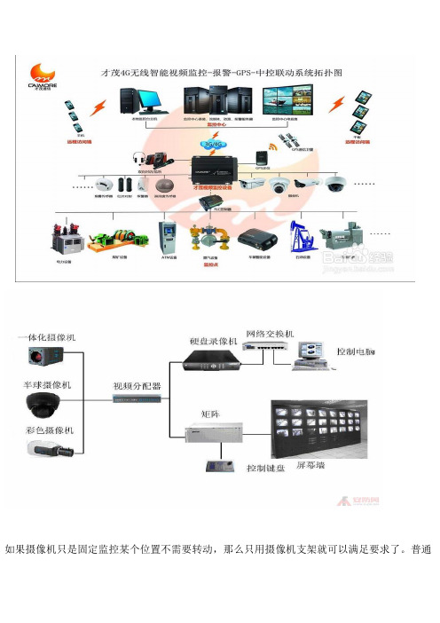
如果摄像机只是固定监控某个位置不需要转动,那么只用摄像机支架就可以满足要求了。
普通摄像机支架安装简单,价格低廉,而且种类繁多。
普通支架有短的、长的、直的、弯的,根据不同的要求选择不同的型号。
室外支架主要考虑负载能力是否合乎要求,再有就是安装位置,因为从实践中我们发现,很多室外摄像机安装位置特殊,有的安装在电线杆上,有的立于塔吊上,有的安装在铁架上……由于种种原因,现有的支架可能难以满足要求,需要另外加工或改进,这里就不再多说了。
室内摄像机的安装高度以2.5~5m为宜,室外以3.5~10m为宜;电梯轿箱内安装在其顶部,与电梯操作器成对角处,且摄像机的光轴与电梯的两壁及天花板成45度。
摄像机的安装注意事项摄像机的使用很简单,通常只要正确安装镜头、连通信号电缆,接通电源即可工作。
但在实际使用中,如果不能正确地安装镜头并调整摄像机及镜头的状态,则可能达不到预期使用效果。
应注意镜头与摄像机的接口,是C型接口还是CS型接口(这一点要切记,否则用C型镜头直接往CS接口摄像机上旋入时极有可能损坏摄像机的CCD芯片)。
安装镜头时,首先去掉摄像机及镜头的保护盖,然后将镜头轻轻旋入摄像机的镜头接口并使之到位。
对于自动光圈镜头,还应将镜头的控制线连接到摄像机的自动光圈接口上,对于电动两可变镜头或三可变镜头,只要旋转镜头到位,则暂时不需校正其平衡状态(只有在后焦聚调整完毕后才需要最后校正其平衡状态)。
调整镜头光圈与对焦关闭摄像机上电子快门及逆光补偿等开关,将摄像机对准欲监视的场景,调整镜头的光圈与对焦环,使监视器上的图像最佳。
如果是在光照度变化比较大的场合使用摄像机,最好配接自动光圈镜头并作摄像机的电子快门开关置于OFF。
如果选用了手动光圈则应将摄像机的电子快门开关置于ON,并在应用现场最为明亮(环境光照度最大)时,将镜头光圈尽可能开大并仍使图像为最佳(不能使图像过于发白而过载),镜头即调整完毕。
装好防护罩并上好支架即可在以上调整过程中,若不注意在光线明亮时将镜头的光圈尽可能开大,而是关得比较小,则摄像机的电子快门会自动调在低速上,因此仍可以在监视器上形成较好的图像;但当光线变暗时,由于镜头的光圈比较小,而电子快门也已经处于最慢(1/50s)了,此时的成像就可能是昏暗一片了。
AXIS 固定半球网络摄像机(通用版) - 用户手册说明书

固定半球网络摄像机(通用版)用户手册责任本文档在制作时已力求审慎。
如发现不准确的内容或遗漏,请及时告知您当地的安讯士办事处。
Axis Communications AB不承诺对技术或印刷错误承担责任,并保留对产品及手册进行变更的权利,恕不另行通知。
Axis Communications AB不对本文档中包含的材料做出担保,包括但不限于为特定目的而对适销性和适用性做出的暗示担保。
Axis Communications AB对于与该材料的提供、执行或使用相关的偶然或间接损坏不承担责任,也不负责。
该产品仅可按其使用意图使用。
知识产权安讯士公司拥有与本文档中所述产品包含的技术相关的知识产权。
特别是(但不限于),这些知识产权可能包括/patent中列出的一项或多项专利,以及美国和其他国家的一项或多项附加专利或待定专利。
本产品包含获得许可的第三方软件。
有关更多信息,请参阅产品用户界面中的菜单项“关于”。
本产品包含符合Apple Public Source License2.0条款的源代码版权Apple Computer,Inc.(请参见/apsl)。
该源代码可从/bonjour/上获取。
设备改造必须严格按照用户文档中给出的说明安装和使用本设备。
本设备不含用户可维修的部件。
未经授权的设备更改或改造将使适用的法规认证和认可无效。
商标声明AXIS COMMUNICATIONS、AXIS和VAPIX是Axis AB在各个辖区的注册商标或商标申请。
其它的公司名称和产品均为其各自公司的商标或注册商标。
Apple、Apache、Bonjour、Ethernet、Internet Explorer、Linux、Microsoft、Mozilla、Real、SMPTE、QuickTime、UNIX、Windows和WWW是其各自持有人的注册商标。
Java 和基于Java的商标和徽标是Oracle和/或其分支机构的商标或注册商标。
摄像机的安装和调试

②④ ⑥
四、安装中出现旳问题以及处理措施
1,视频输出时,影响跳动,原因是线接触不良, 需要重新检验接线。
2,控制键盘无法控制摄像机旳转动,原因是 RS-485线旳正负极接反了,需要重新接线。。
调试成功
枪式摄像机旳安装与调试
(二)接线 5.连接视频线接头
接法:将视频线接头旳芯线 接在正极上,撮紧旳金属 屏蔽线接在负极上,正确旳
位置,如图所示:
枪式摄像机旳安装与调试
(三)测试视频输出
回环节
枪式摄像机旳安装与调试
三、安装中轻易出现旳问题与处理措施
1,电源旳正负极接反,会烧坏摄像机,所以通电前 一定要检验好电源是否接错!
枪式摄像机旳安装与调试
(二)接线
3.制作视频线接头
把BNC接头旳另一端,用 剪刀剥掉最外面旳护套, 约2cm左右。然后把屏蔽金 属丝紧紧地缠绕起来。
枪式摄像机旳安装与调试
(二)接线 3. 制作视频线接头
用剪刀将露出来旳绝缘介质(白色旳塑料管)剪掉约
1.5cm左右,(注意不要太用力,以免剪断里面旳芯线)。
Zoom FoCom 公共C
相当于菜单
在这个类型摄像 机上,紫色线, 没有用到,此类 摄像机能够自动 调整光圈大小, 是傻瓜摄像机一 类。
SW2 地址开关位号 把地址转化为二进制,若 二进制位为1,就把相应旳 开关拨上去,若为0,就不 用拨上去。 例:我们组为6号,即为 01100000.则把2,3号拨 上去。
注意:下面旳正极接上面旳负极, 一样,下面旳负极接上面旳正极。
三‘连接到电视墙
摄像机 拍摄图像
连接
控制键盘 控制摄像 机旳工作
电视墙上 输出视频
回目录
摄像机安装调试步骤

画面亮度,可在60-90范围内调节 对比度建议30,对比度越高,亮的地方越亮暗的地方越暗,白 天层次感越强,晚上需要稍微调低一点,可以更多的显示 暗处的
日夜转换
日夜模式选择白天模式,使其保持彩色效果
数字降噪
数字降噪使用专家模式,建议时域50,空域20
降噪在滤除噪点的同时可能也会将有效信息特别是车牌信息细节滤除, 所以不宜太高,具体根据噪点和车牌效果寻找一个平衡点即可
Байду номын сангаас
“摄像机前端参数配置”
曝光
曝光时间选择自定义8000us,也可根据需要在1/100S-1/250S设置 曝光时间越短图像整体亮度越低,但是对快速运动的车辆看车牌越清 晰,不易出现拖影
镜头光圈
镜头光圈 选择手动光圈模式
视频参数---对比度、亮度
亮度建议70,亮度参数夜间在快门较低的情况下可以提高整体
建议10-15°
补光灯
补光灯位置尽量对着监控区域压低压近
补光灯与摄像机也尽量有一个水平距离(1-2米),避免灯光直射
安装示意图
调试-1 聚焦
变焦镜头先使用W-T选好焦距场景,再使用F-N聚焦调节, 手动光圈将光圈调至最大, 聚焦距离建议设备离车牌观测 点直线水平距离15-25米,选定场景中心点为参考,聚焦至 最佳位置,锁紧螺钉
调试-2 前端参数配置
摄像机安装聚焦完毕后一般白天都没有问题,前端参数配 置主要针对夜晚情况
前端参数主要需要调试的包括以下几项:
曝光(快门时间) 镜头模式(光圈模式) 对比度 亮度 3D降噪 日夜转换
进入前端参数配置 在预览画面里鼠标右击,选择“摄像机前端参数配置”
网络摄像机
——安装、调试指南
安讯士h4a-bo高清枪机安装手册-中文说明书

安装指南Avigilon™ H4 高清子弹型摄像机型号:H4A-BO1-IR(-B)、H4A-BO2-IR(-B)、H4A-G-BO1-IR(-B)、H4A-G-BO2-IR(-B)重要安全信息本手册针对本摄像机的使用提供有关安装与操作信息以及预防措施。
安装不当可能导致意外故障。
安装本设备之前,请仔细阅读本手册。
请为设备用户提供本手册,以备日后使用。
l安装设备仅限合格人员来完成,且必须符合当地所有法规。
l本产品的专用电源是标有“2 级”或“LPS”或“有限功率电源”的 UL 认证电源单元,额定输出电压为 12 VDC 或24 VAC,最小功率为 13 W,或采用太网供电 (PoE),额定电压为 48 VDC,最小功率为 13 W。
l与本产品连接的任何外部电源只能与同型号系列的其他 A vigilon 产品连接。
外部电源接头必须进行适当绝缘。
l严禁与市供电源直接连接。
l请勿将摄像机直接暴露于高水平的 x 光、激光或 UV 辐射。
直接曝光可能会导致图像传感器永久损坏。
l请勿安装在任何热源附近,比如散热器、热风口、炉灶或其他热源。
l请勿使设备电缆压力过大、 负荷过重或挤压过度。
l请勿拆开或拆解设备。
产品不含用户可自行维修部件。
l将所有设备维修交给合格人员。
可能需要维修的情况有以下几种:摄像机损坏(比如,因液体溅湿或坠落物而损坏),受雨淋或受潮,不正常运行或者掉落。
l清洁设备机身时,请勿使用强效洗涤剂或腐蚀性洗涤剂。
l仅使用 Avigilon 推荐的附件。
l本产品应安装在受限制的接触位置。
合规声明本设备符合 FCC 规则的第 15 部分规定。
摄像机运行遵守以下两个条件:(1)本设备不会产生有害干扰;(2)本设备必须承受收到的任何干扰,包括可能导致意外运行的干扰。
本 B 类数码设备符合加拿大 ICES-003 标准。
测试结果表明,根据 FCC 规程第 15 部分,本设备符合 B 类数码设备的规定。
这些规定用于提供合理保护,以免在住宅区安装过程中受到有害干扰。
安讯士 AXIS P3125-Z 室内型半球网络摄像机说明书

数据表AXIS P3125-Z网络摄像机小巧灵活的嵌入式高清半球摄像机AXIS P3125-Z室内型半球网络摄像机,可提供HDTV1080p的高清视频质量。
AXIS P3125-Z网络摄像机支持觅光者技术,在低光照条件下实现了更好的彩色重现。
此款摄像机支持H.265和安讯士Zipstream 技术,在保证视频质量的同时能够大幅降低带宽和存储要求。
AXIS P3125-Z网络摄像机小巧、灵活,独特的嵌入式设计,能直接嵌入射灯的位置,露出吊顶部分的高度仅42毫米,与天花板吊顶装饰浑然一体。
同时,集成了音频、I/O和电源接口,满足多种不同的使用需求。
AXIS P3125-Z网络摄像机,是零售店、酒店、学校等进行24小时视频监控的更佳选择。
>HDTV高清视频质量>安讯士觅光者技术>安讯士Zipstream技术>双向音频,I/O,本地电源>支持H.265AXIS P3125-Z网络摄像机摄像机图像传感器逐行扫描RGB CMOS1/2.8”镜头手动变焦镜头,2.8–6毫米,F2.0水平视角100°–53°垂直视角73°–40°日夜可自动移除的红外截止滤光片最低照度彩色:0.15lux、F2.0、黑/白:0.04lux、F2.0快门时间1/62500秒至1/6秒平移/倾斜/变焦水平转动±178°,垂直转动±60°,旋转±178°视频视频压缩H.264Main和High ProfileH.265Motion JPEG分辨率1920x1080至240x135帧速率高达50/60fps(50/60Hz)视频流多路可分别配置的H.264、H.265和Motion JPEG格式的视频流采用安讯士Zipstream技术可控帧速与带宽VBR/CBR H.264、H.265多视点视频流8个分别裁剪的视点图像设置压缩率、色彩、亮度、锐度、对比度、白平衡、曝光控制(包含自动增益控制)、曝光区域、背光补偿、在不同光照级别下的行为微调、局部对比度、文本和图像叠加、图像镜像、隐私遮罩、宽动态范围—对比技术旋转度:0°、90°、180°、270°,包括走廊格式平移/倾斜/变焦数字PTZ音频音频流双向、全双工音频压缩AAC-LC8/16kHz、G.711PCM8kHz、G.726ADPCM8kHz可配置的比特率音频输入线路输入接口音频输出线路输出接口网络安全密码保护、IP地址过滤、HTTPS a加密、IEEE802.1X a网络访问控制、摘要式身份验证、用户访问日志、集中式证书管理支持的协议IPv4/v6、HTTP、HTTPS a、SSL/TLS a、QoS Layer3DiffServ、FTP、CIFS/SMB、SMTP、Bonjour、UPnP TM、SNMP v1/v2c/v3(MIB-II)、DNS、DynDNS、NTP、RTSP、RTP、SFTP、TCP、UDP、IGMP、RTCP、ICMP、DHCP、ARP、SOCKS、SSH系统集成应用程序编程接口用于软件集成的开放式API,包括VAPIX®和安讯士摄像机应用平台,规范网址:ONVIF®Profile S和ONVIF®Profile G,规范网址:智能分析AXIS Video Motion Detection4、主动防篡改报警音频侦测支持AXIS摄像机应用平台,能够安装第三方应用,请访问/acap事件触发智能分析、前端存储事件,外部输入事件动作外部输出文件上传:FTP、SFTP、HTTP、HTTPS、网络共享和电子邮件通知:电子邮件、HTTP、HTTPS、TCP和SNMP自陷视频录制到前端存储中报警前和报警后视频缓冲发送视频剪辑叠加文本数据流事件数据内置安装帮助像素计数器常规存储器512MB RAM,256MB闪存电源12V DC,24V AC以太网供电,符合IEEE802.3af Class2标准最大4W接口RJ4510BASE-T/100BASE-TX PoE接口*1,12V DC/24VAC电源接口*1,音频接口*1,I/O接口*2存储支持microSD/microSDHC/microSDXC卡支持录制到网络附加存储(NAS)有关SD卡的更多信息,请访问工作条件0°C至55°C湿度10-85%相对湿度(无冷凝)存放条件–40°C至65°C认证型检报告尺寸高度:153毫米露出吊顶的高度:42毫米直径:88毫米安装开孔直径:64毫米重量192克所含附件安装指南、Windows解码器单用户许可证、装配卡环视频管理软件AXIS Companion、AXIS Camera Station、AVMS、安讯士的应用开发合作伙伴的视频管理软件可在/support/downloads上获得质保安讯士3年保修和安讯士延期保修选项,详情请访问/warrantya.本产品包含由OpenSSL Project开发用于OpenSSL Toolkit()的软件,以及由Eric Young(*****************)编写的加密软件。
监控摄像机基本使用方法和安装操作
监控摄像机基本使用方法和安装操作目录:1.引言2.摄像机选择与安装2.1 摄像机类型2.2 选择摄像机2.3 安装位置选择2.4 安装步骤3.连接与配置摄像机3.1 网络连接3.2 配置IP地址3.3 设置摄像机参数4.监控系统软件操作4.1 软件安装4.2 登录系统4.3 实时监控4.4 录像回放5.监控摄像机维护5.1 摄像机定期检查5.2 固件升级5.3 存储设备管理5.4 故障排除6.附件7.法律名词及注释8.结束1.引言本文档旨在详细介绍监控摄像机的基本使用方法和安装操作,帮助用户快速上手使用和配置摄像机。
2.摄像机选择与安装2.1 摄像机类型根据需求选择合适的摄像机类型,包括室内摄像机、室外摄像机、固定球机、云台球机等。
2.2 选择摄像机根据监控区域的大小和需求选择适合的摄像机型号和性能指标,如分辨率、变焦倍数等。
2.3 安装位置选择根据监控区域的结构和特点选择合适的安装位置,确保覆盖范围和监控效果。
2.4 安装步骤按照摄像机的安装说明进行安装,包括固定安装支架、连接电源和网络等。
3.连接与配置摄像机3.1 网络连接将摄像机与网络交换机或路由器连接,确保摄像机与监控系统能够互相通信。
3.2 配置IP地址根据实际情况配置摄像机的IP地址,确保能够与其他设备正常通信。
3.3 设置摄像机参数根据需求设置摄像机的参数,如视频分辨率、帧率、码率等,以及图像增强和移动侦测等功能。
4.监控系统软件操作4.1 软件安装安装监控系统软件,并按照软件说明进行配置和登录。
4.2 登录系统使用正确的用户名和密码登录监控系统,获取实时监控和录像回放等功能。
4.3 实时监控通过监控系统软件查看摄像机实时画面,并进行云台控制、图像调整和拍照等操作。
4.4 录像回放查看和回放录像文件,并进行搜索、导出和保存等操作。
5.监控摄像机维护5.1 摄像机定期检查定期检查摄像机的工作状态和图像质量,确保正常运行。
5.2 固件升级及时升级摄像机的固件,以获取最新的功能和修复已知的问题。