BTP-1000PTII用户手册VER2
BTP-1000PTII用户手册VER2

BTP-1000PTII标签打印机用户手册山东新北洋信息技术股份有限公司声明本手册内容未经同意不得随意更改,山东新北洋信息技术股份有限公司(以下简称新北洋)保留在技术、零部件、软件和硬件上变更产品的权利。
用户如果需要与产品有关的进一步信息,可与新北洋或经销商联系。
未得到新北洋的书面许可,本手册的任何章节不得以任何形式、通过任何手段进行复制或传送。
本手册内容如有任何变动,恕不另行通知。
版权本手册于2007年印制,版权属于新北洋。
中国印制。
2.0版本。
商标新北洋使用的注册商标是警告、注意警告必须遵守,以免伤害人体,损坏设备。
注意给出了打印机操作的重要信息及提示。
新北洋质量管理体系通过下列认证:挪威船级社(DNV)ISO9001:2000 认证本产品已通过下列认证:安全须知在操作使用打印机之前,请仔细阅读下面的注意事项。
安全警告警告:打印头为发热部件,打印过程中和打印刚结束不要触摸打印头以及周边部件。
警告:不要触摸打印头表面和连接插件,以免因静电损坏打印头。
注意事项1)打印机应安装在一个平整、稳固的地方;2)在打印机的周围留出足够的空间,以便操作和维护;3)打印机应远离水源并避免阳光、强光和热源的直射;4)不要在高温、高湿以及污染严重的地方使用或保存打印机;5)避免将打印机放在有振动或冲击的地方;6)避免打印机表面结露,一旦形成,待露水消失后才可打开电源;7)将打印机的电源适配器连接到一个适当的接地插座上。
避免与大型电机或其它能够导致电源电压波动的设备使用同一插座;8)如果较长时间不使用打印机,请断开打印机电源;9)避免水或导电的物质(例如:金属)进入打印机内部,一旦发生,应立即关闭电源;10)打印机不得在无纸状态下打印,否则将严重损害打印头和胶辊;11)连接/断开各接口时,必须关闭电源,避免打印机控制电路损坏;12)在打印效果满足使用要求的前提下,建议设置尽可能低等级的打印浓度,以提高打印头的使用寿命;13)在压下打印头组件前必须先压下压纸组件,否则不能正常打印;14)用户不得自行拆卸打印机进行检修。
袋牌打印机配置手册新北洋btp1000pt②安装使用说明
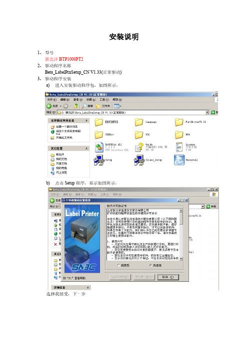
安装说明1、型号新北洋BTP1000PT22、驱动程序名称Beta_LabelPrnSetup_CN V1.33(正常驱动)3、驱动程序安装a) 进入安装驱动程序包,如图所示:b) 点击Setup程序,显示如图所示:选择我接受,下一步标签打印机选择BTP-6200I,点击下一步如图:下一步如图:再点击下一步如图:选择端口号每秒位数选择:19200 其他默认,之后点击安装。
成功提示:c) 安装打印机驱动成功4、配置打印机打开开始菜单,选择打印机和传真。
图1.1打印机和传真5、配置袋牌打印机的纸张右键如图:图1.1打印机和传真空白处。
弹出如图所示:选择创建新格式,填写表格名:BTY-daipai并填写宽度为:5.00高度为:8.10点击确定。
纸张配置完毕。
6、配置打印机的属性右键打印机弹出框,选择属性,如图:点击属性后如图显示:并修改如上图红色部分,修改DPprinter名字。
选择端口选项,如图:端口号选择插入的端口,每秒的位数:19200 其他默认确定。
选择设备设置:选择设置东纸张大小,Envelope-daipai。
7、打印机首选项设置,右键DPprinter,显示如图:选择打印首选项,上述图选择打印选项,图形旋转选择旋转180度打印。
切换到布局,选择高级,弹出如下图:纸张规格选择设计的上述设计的。
北洋打印机调试软件使用1.打开通讯和调试选择端口设置。
点击端口设置,显示如下图:配置串口名称,选择终端的接口,每秒位数为:19200其他默认确定。
2.点击工具选择配置设置,如下图:点击读打印机,在点击读文件。
,选择武汉上海路邮政1000pt2标准配置。
之后点击更新配置。
之后回到主页面点击复位。
重新启动打印机。
打印机安装配置完成。
谢谢观看!。
RP1000P2SFP 系列万兆以太网适配器 用户手册说明书
RP1000P2SFP系列万兆以太网适配器用户手册北京网迅科技有限公司版权声明本手册所有内容,其版权属于北京网迅科技有限公司(以下简称北京网迅)所有,未经北京网迅许可,任何单位和个人不得仿制,拷贝,转译或者任意引用。
版权所有不得翻印文件更改历史记录初始信息文件名称RP1000P2SFP系列万兆以太网适配器用户手册初始版本号V1.00 发布日期2019.11编写人章圣表批准人杨友华更改记录版本号更改要点修改人批准人批准发布日期V1.00 初始版本章圣表杨友华2019.11.22 V1.01 驱动程序安装章节修改章圣表杨友华2020.6.1 V1.02 驱动程序安装章节修改高登奎杨友华2020.7.3 V1.03 驱动程序安装章节修改高登奎杨友华2021.1.7 V1.04 驱动程序安装章节修改高登奎杨友华2021.6.1V1.05 增加文件修改历史记录,驱动程序章节修改,增加产品型号章圣表杨友华2021.6.23V1.06 光模块支持列表增加两个型号章圣表杨友华2021.12.22第1章 RP1000P2SFP系列万兆以太网适配器简介RP1000P2SFP系列万兆以太网适配器(以下简称以太网适配器)是基于北京网迅自主设计的企业级以太网控制器主芯片SP1000A,拥有自主知识产权,它能满足企业数据中心对网络最新需求,应用在服务器上,支持管理程序分流数据排序功能,通过有效地平衡网络负载在CPU核上,提高数据吞吐量和CPU使用率,,在多CPU处理器系统中表现出极佳的性能。
RP1000P2SFP系列万兆以太网适配器具有优良的噪声抗扰性,同时还支持300米距离光纤连接,适用于服务器和高端设备,它可轻松将任何PCI Express X8集成到万兆网络中,并且对性能进行了优化,使系统I/O不再是高端网络应用的瓶颈。
RP1000P2SFP系列万兆以太网适配器带有两个完全集成的万兆以太网媒体存取控制(MAC)和SFP+端口,它是部署在企业级多个网络以及在高性能服务器上部署关键网络应用环境的理想解决方案。
Parker Pneumatic PDN1000-2US 产品说明书
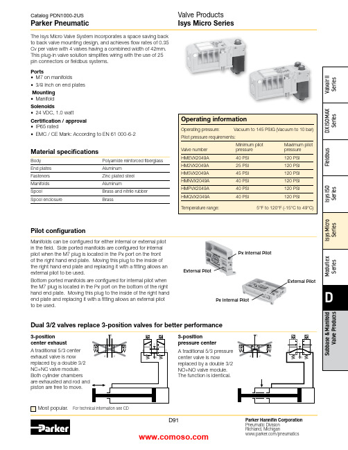
Material specificationsBody Polyamide reinforced fiberglass End plates Aluminum Fasteners Zinc plated steel Manifolds AluminumSpoolBrass and nitrile rubber Spool enclosureBrassMost popular.For technical information see CDThis plug-in valve solution simplifies wiring with the use of 25 pin connectors or fieldbus systems.Ports• M7 on manifolds• 3/8 Inch on end platesMounting • ManifoldSolenoids• 24 VDC, 1.0 wattCertification / approval • IP65 rated• EMC / CE Mark: According to EN 61 000-6-2Manifolds can be configured for either internal or external pilot in the field. Side ported manifolds are configured for internal pilot when the M7 plug is located in the Px port on the front of the right hand end plate. Moving this plug to the inside of the right hand end plate and replacing it with a fitting allows an external pilot to be used.Bottom ported manifolds are configured for internal pilot when the M7 plug is located in the Px port on the bottom of the right hand end plate. Moving this plug to the inside of the right hand end plate and replacing it with a fitting allows an external pilot to be used.External PilotPx Internal PilotPx Internal PilotExternal Pilot3-positioncenter exhaustA traditional 5/3 center exhaust valve is now replaced by a double 3/2 NC+NC valve module. Both cylinder chambers piston are free to move.Dual 3/2 valves replace 3-position valves for better performance3-positionpressure center A traditional 5/3 pressure center valve is nowreplaced by a double 3/2 NO+NO valve module. The function is identical.Pilot configurationPlug-in valve manifolds Part numbers Side port Bottom port Single solenoid outputs onlyPSM21JAPPSM22JAP Double or single solenoid outputsPSM21MAPPSM22MAPIsys Micro ValvesSymbolTypeCv Operator Part numberInternal Pilot End Plate KitsElectrical option Porting Side port Bottom portSimple Manifold Assemblies** Requires fitting “P”.BOLD OPTIONS ARE MOST POPULAR.N 7D 1516Valve Position A - Character 9Fitting Position A - Character 10Valve Position C - Character 13Fitting Position C - Character 14Valve Position B - Character 11Fitting Position B - Character 12Valve Position D - Character 15Fitting Position D - Character 16ACDACDBBIncludes a valve manifold with 4 valves and fittings installed. End Plates must be ordered separately.1. List Add-A-Fold Assembly call out. This automatically includes the end plate kit assembly.2. List Simple Manifold Assemblies. List left to right, LOOkING AT ThE CyLINDER PORTS on the manifold.Maximum Number of Solenoids(Maximum Energized Simultaneously)25-pinD-sub Moduflex Isysnet*Turck16Outputs32Outputs 24VDC24 (24)16 (16)32 (32)16 (16)32 (32) * Maximum of 32 solenoids per manifold. With Bus Extension functionality,4 manifolds with up to 32 solenoids each can be connected on the same network.Add-A-Fold Assembly Model NumberHow To Order Plug-in Add-A-Fold AssembliesNote:BSPP fittings can only be used with BSPP Manifolds.NPT fittings can only be used with NPT Manifolds.Sandwich RegulatorFlow Controls2-position and Dual 3/2 valves, and 0.17 for 3-position APB valves.Note: The sandwich regulator passes full pilot pressure from the manifold,allowing the regulated pressure to adjusted down to 5 PSI without affecting valve functionality.25-pin, D-Sub ManifoldsComponent LevelItem Qty Description Part number 01125-pin, D-sub, end plate PSML25AP0224Single solenoid valveHMEVX2049A 036Manifold, side ported, single address PSM21JAP 04501/4" Tube fittings (in box quantity)PS56792505103/8" Tube fittings (in box quantity)PS5683380613/8" Exhaust muffler P6M-PAB30711/8" Exhaust mufflerP6M-PAB1Add-A-FoldManifold is factory assembled and tested for pneumatic leaks and electrical continuity.Item Qty Description Part number 01124 valve Add-A-Fold with end platesAAHMD5249M0M 0264 valve simple manifold slices #1-6PSM31JAPE7E7E7E725-pin, D-Sub Cable (Female)DescriptionLengthPart number25-pin, D-sub cable, IP20 3 meters P8LMH25M3A 25-pin, D-sub cable, IP209 meters SCD259D 25-pin, D-sub cable, IP65 3 meters SCD253W 25-pin, D-sub cable, IP659 meters SCD259WE24 Single Solenoid ValvesManifold Slice #1Manifold Slice #2Manifold Slice #3Manifold Slice #5Manifold Slice #4Manifold Slice #6MufflersFittings – Must be ordered in multiples of 10ThreadTube O.D.Part numberPSM0001 –All ports open. Common pressure for front and rear mon exhausts.Standard gasket included with each manifold and end plate.Back Row OpenCommon Front Row OpenPSM0001PSM0001PSM0002 –Rear manifold blocked for separate pressure mon exhausts.Flip gasket to block front of manifold.Back Row BlockedCommon Front Row OpenPSM0002PSM0002Intermediate* Qty. (2) PSM0002 Gaskets are required.Remainder are PSM0001 Gaskets (Not shown)Internal Pilot Pressure from P1 InletPSM0003 –Rear manifold blocked for separate pressure supply.Exhaust blocked also.Flip gasket to block front of manifold.If used with bottom ported end plates, second exhaust must be piped from the side of the right end plate.Back Row Blocked Common Front Row OpenIntermediatePSM0003PSM0003PSM0002PSM0002* Qty. (1) PSM0003 and Qty. (1) PSM0002 Gaskets are required.Remainder are PSM0001 Gaskets (Not shown)Internal Pilot Pressure from P1 Inlet PSM0004 –All galleys blocked.Two pressure zones and two exhaust zones.If used with bottom ported end plates, second exhaust must be piped from the side of the right end plate.PressurePressureExhaustExhaustBack Row Blocked Common Front Row BlockedIntermediate * Qty. (1) PSM0004 Gasket is required.Remainder are PSM0001 Gaskets (Not shown)PSM0004PSM0001PSM0004PSM0001Internal Pilot Pressure from P2 InletMultiple Pressure ZonesReplacement ScrewsManifold to Manifold Gaskets*Valve Labels*Replacement Solenoid Kit Replacement Override Caps Replacement Regulator GaugeReplacement Protective CoverReplacement Gaskets and Valve ScrewsReplacement PlugsDescription Part numberDimensionsA 4.88 (124.0)B 4.41 (112.0)C 2.95 (75.0)D 1.65 (42.0)E 1.22 (31.0)F 1.02 (26.0)G 0.71 (18.0)H 0.49 (12.5)J 2.28 (58.0)K 3.44 (87.5)M 0.24 (6.1)N 0.21 (5.2)P 0.41 (10.5)per ManifoldBottom PortedDetail25-pin, D-Sub with Isys Micro Valves, Bottom Ported25-pin, D-Sub with Isys Micro Valves, Side PortedInches (mm)Inches (mm)per ManifoldSide Portedn = Number of manifoldsn = Number of manifoldsDimensionsA 4.88 (124.0)B 4.41 (112.0)C 2.95 (75.0)D 1.65 (42.0)E 1.22 (31.0)F 1.02 (26.0)G 0.71 (18.0)H 0.49 (12.5)J 2.28 (58.0)K 3.44 (87.5)L 1.69 (43.0)M 0.24 (6.1)N 0.21 (5.3)P 0.62 (15.8)Q 1.03 (26.3)R 1.45 (36.8)S 0.64 (16.40)T 1.14 (29.0)U 3.73 (94.9)V 4.23 (107.4)Isysnet with Isys Micro Valves, Bottom PortedDimensionsA 5.67 (144.0)A 14.88 (124.0)B 4.41 (112.0)B 15.24 (133.0)B 24.02 (102.0)C 2.95 (75.0)D 1.65 (42.0)E 0.91 (23.0)G 0.71 (18.0)H 0.49 (12.5)J 2.72 (69.0)K 7.32 (186.0)M 0.24 (6.1)N 2.83 (72.0)Q 1.81 (46.0)R 4.72 (120.0)S 2.01 (51.0)T 2.01 (51.0)DimensionsA 5.67 (144.0)A 14.88 (124.0)B 4.41 (112.0)B 15.24 (133.0)B 24.02 (102.0)C 2.95 (75.0)D 1.65 (42.0)E 0.91 (23.0)G 0.71 (18.0)H 0.49 (12.5)J 2.72 (69.0)K 7.32 (186.0)L 1.69 (43.0)M 0.24 (6.1)N 2.83 (72.0)Q 1.81 (46.0)R 4.72 (120.0)S 2.01 (51.0)T 2.01 (51.0)U 4.41(112)per ManifoldInches (mm)Inches (mm)n = Number of Manifolds m = Number of Modulesn = Number of Manifolds m = Number of ModulesModuflex with Isys Micro Valves, Bottom Ported0.25 (6.4) per Manifold0.25 (6.4) DimensionsA 4.88 (124.0)B 4.41 (112.0)C 2.95 (75.0)D 1.65 (42.0)E 1.22 (31.0)F 1.02 (26.0)G 0.71 (18.0)H 0.49 (12.5)J 2.28 (58.0)K 6.10 (155.0)L 1.69 (43.0)M 0.24 (6.1)N 2.40 (61.0)P 2.36 (60.0)Q 2.07 (52.55)Inches (mm)Inches (mm)n = Number of manifoldsn = Number of manifoldsDimensionsA 4.88 (124.0)B 4.41 (112.0)C 2.95 (75.0)D 1.65 (42.0)E 1.22 (31.0)F 1.28 (32.5)G 0.71 (18.0)H 0.49 (12.5)J 2.28 (58.0)K 6.10 (155.0)M 0.24 (6.1)N 2.40 (61.0)P 2.36 (60.0)Q 2.07 (52.55)Catalog PDN1000-2US Parker PneumaticParker Hannifin Corporation Pneumatic Division Richland, Michigan /pneumaticsD101Valve Products Isys Micro Series Dimensions Turck with Isys Micro Valves, Side PortedDimensions A 7.48 (190)B 5.51 (140)C 5.71 (145)D 0.20 (5)F 1.28 (32.5)G 3.79 (96.5)H 5.06 (128.5)J 2.53 (64.5)K 1.26 (32)L 2.54 (64)M See note 1N 2.28 (58)P 1.65 (42)Q .19 (4.9)R 4.41 (112)S 4.88 (124)Note 1: M =J+L+n 2xk, where n 2 = Number of Turck input / output modules Inches (mm)。
1000P Non-Powered Short Haul Modem 使用手册说明书

1
Date Rates: Transmission Format: Transmission Mode: Connectors - RS-232:
Connectors - Line:
Surge Protection: Factory Switch Setting:
Cable Type:
19,200 bps (according to the RS232 interface)
With an externally accessible DCE/DTE switch, the Model 1000P allows easy connection to any device without opening the unit. Three enclosure options allow terminations to be via RJ-11, RJ-45 or terminal blocks. A unique strain relief prevents thin twisted pairs from breaking or pulling loose.
Compliant with IEC 801.5 level 2, 1kV (Model 222NS Only)
DCE; data is received from the remote short range modem via RX+ and RX-, and is sent to the DTE from the Model 222N via pin 3 of the RS-232 interface; (the RS232 interface is the DB-25 connector closest to the DTE/DCE switch).
Philips 芯片电子刮胡子系列1000 BT1005 10用户手册说明书

Beardtrimmer series1000Pro Skin Trimmmer4 built-in length settingsAA battery operatedUp to 2 months of usage*BT1005/10Pro Skin TrimmerLong lasting performance, no skin compromiseThe Philips Beardtrimmer Series 1000 delivers skin friendly trimming results timeafter time. Use the trimmer up to 2 months with one set of batteries.Skin-friendly trimmerSkin-friendly rounded tips for smooth skin contactLength settings from 1.5mm to 7mm, 0.5mm without the combContour following comb for a precise and even trimLong lasting performanceUp to 120 min cordless useBuilt to last2 year world wide warranty, no oil neededPop open head makes it easy to clean with the added brushBeard trimmerBT1005/10HighlightsSpecificationsSkin-friendly high-performanceBlades stay extra-sharp to always cut hairs neatly and effectively, but have rounded blade tips and combs to prevent irritation.4 built-in length settingsSlide the comb up to the desired length setting,from 1.5 to 7mm or use it without the comb for a 0.5mm stubble.Built to lastAll of our grooming products are built to last.They come with a 2 year worldwide warranty and they never need to be oiled.Easy to cleanSimply pop the trimmer head open and use the cleaning brush included to sweep away loose hairs.Long lasting battery lifeUp to 2 months of usage with one set of batteries, 120 minutes cordless power. (AA batteries are not included)Contour following combFlexing guide comb that follows every curve of your face for getting an even trim in an easy and comfortable way.Cutting systemCutting element: Stainless steel blades Non-scratching teeth: For more comfort AccessoriesMaintenance: Cleaning brush Ease of useCleaning: Pop open headDesignColor: BlackPowerBattery Type: AA battery (not included)Service2-year warranty No oil needed* With Alkaline AA, LR6, 1.5V batteries© 2019 Koninklijke Philips N.V .All Rights reserved.Specifications are subject to change without notice. Trademarks are the property of Koninklijke Philips N.V . or their respective owners.Issue date 2019‑07‑02Version: 1.3.1EAN: 08 71010 37240 70。
【VIP专享】袋牌打印机配置手册:新北洋btp1000pt②安装说明

安装说明1、型号新北洋BTP1000PT22、驱动程序名称Beta_LabelPrnSetup_CN V1.33(正常驱动)3、驱动程序安装a)进入安装驱动程序包,如图所示:b)点击Setup程序,显示如图所示:选择我接受,下一步标签打印机选择BTP-6200I,点击下一步如图:下一步如图:再点击下一步如图:选择端口号每秒位数选择:19200 其他默认,之后点击安装。
成功提示:c)安装打印机驱动成功4、配置打印机打开开始菜单,选择打印机和传真。
图1.1打印机和传真5、配置袋牌打印机的纸张右键如图:图1.1打印机和传真空白处。
弹出如图所示:选择创建新格式,填写表格名:BTY-daipai并填写宽度为:5.00高度为:8.10点击确定。
纸张配置完毕。
6、配置打印机的属性右键打印机弹出框,选择属性,如图:点击属性后如图显示:并修改如上图红色部分,修改DPprinter名字。
选择端口选项,如图:端口号选择插入的端口,每秒的位数:19200 其他默认确定。
选择设备设置:选择设置东纸张大小,Envelope-daipai。
7、打印机首选项设置,右键DPprinter,显示如图:选择打印首选项,上述图选择打印选项,图形旋转选择旋转180度打印。
切换到布局,选择高级,弹出如下图:纸张规格选择设计的上述设计的。
北洋打印机调试软件使用1.打开通讯和调试选择端口设置。
点击端口设置,显示如下图:配置串口名称,选择终端的接口,每秒位数为:19200其他默认确定。
2.点击工具选择配置设置,如下图:点击读打印机,在点击读文件。
,选择武汉上海路邮政1000pt2标准配置。
之后点击更新配置。
之后回到主页面点击复位。
重新启动打印机。
打印机安装配置完成。
谢谢观看!。
Philips 无线蓝牙小型音箱 BT1000 说明书

PhilipsEnceinte portable sans filBluetooth ®Micro intégré pour la prise d'appelBatterie rechargeable 2 WBT100BVotre musique avec vous en permanenceD'une compacité pratique en déplacement, offrant un excellent son, tout un choix de couleurs ainsi qu'une fonction de streaming sans fil Bluetooth ®, le BT100 est idéal pour le globe-trotter féru de mode qui sommeille en vous.Un son impressionnant•Performances audio de pointe et design compact•Filtre anti-distorsion pour un son puissant, non saturéSimplicité d'utilisation•Micro intégré pour des appels téléphoniques en mains libres•Entrée audio, pour une connexion facile à la plupart des appareils •Profitez de votre musique sans fil grâce au Bluetooth ®Prêt à l'emploi•Batterie intégrée pour une utilisation en tout lieuDate de publication 2017-09-09Version: 2.1.512 NC: 8670 001 12964EAN: 08 71258 17145 12© 2017 Koninklijke Philips N.V.Tous droits réservés.Les caractéristiques sont sujettes à modification sans préavis. Les marques commerciales sont la propriété de Koninklijke Philips N.V. ou de leurs détenteurs CaractéristiquesEnceinte portable sans filBluetooth® Micro intégré pour la prise d'appel, Batterie rechargeable, 2 WPoints fortsProfitez de votre musique sans filLe Bluetooth ® est une technologie decommunication sans fil à courte portée fiable et peu gourmande en énergie. Cette technologie permet une connexion sans fil facile à un iPod/iPhone/iPad ou d'autres appareils Bluetooth ® tels que des smartphones, des tablettes ou même desordinateurs portables. Ainsi, cette enceinte pourra diffuser facilement sans fil vos musiques préférées et le son de vos jeux ou vidéos.Filtre anti-distorsionLe filtre anti-distorsion vous permet d'écouter de la musique plus fort sans baisse de qualité, même lorsque la batterie est presque déchargée. Elleaccepte les signaux d'entrée compris entre 300 mV et 1 000 mV, et évite que la distorsion n'endommage vos enceintes. Cette fonction intégrée contrôle le signal musical transmis par l'amplificateur en faisant en sorte que les pics restent dans la gamme de fréquences de l'amplificateur, afin d'éviter ladistorsion due à l'écrêtage sans affecter le volume. La capacité d'une enceinte portable à reproduire les pics sonores diminue avec le niveau de charge de la batterie, mais le filtre anti-distorsion réduit les pics causés par ce faible niveau.Microphone intégréAvec son micro intégré, cette enceinte permet également de prendre des appels en mains libres. Lorsque l'on vous appelle, la musique est mise en pause, et vous pouvez parler via l'enceinte. Réalisez une conférence téléphonique au travail, ou appelez un ami pendant une soirée. Quelles que soient les circonstances, vous ne serez pas déçu.Entrée audioEntrée audio, pour une connexion facile à la plupartdes appareilsCompatibilité•iPad: iPad 1, iPad 2, nouvel iPad, iPad mini, iPad avec écran Retina•iPhone: iPhone 3, iPhone 3GS, iPhone 4, iPhone 4S, iPhone 5, iPhone 5C, iPhone 5S•iPod Touch: 3e génération ou ultérieur •Tablettes et smartphones Android: avec Android 2.1 et Bluetooth ® 2.1 ou supérieur •compatible avec: Bluetooth ® 4.0 ou inférieur •autre appareil BluetoothDesign et finition•Couleur: Noire Connectivité•Profils Bluetooth ®: A2DP, AVRCP, HFP •Portée Bluetooth ®: 10 m (champ libre)•Entrée audio (3,5 mm)•Rechargeable via USBPratique•Microphone intégré: pour des appels en conférence via l'enceinteSon•Puissance de sortie (RMS): 2 W •Système audio:MonoEnceintes•Haut-parleur: 1 x 1,75"Alimentation•Autonomie pile: 8 h•Type de batterie: Lithium-polymère (intégrée)Accessoires•Accessoires fournis: Câble USB de recharge PC, Livret de garantie internationale, Guide d'installation rapideDimensions•Dimensions du produit (l x P x H): 63 x 63 x 82 millimètre•Dimension de l'emballage (l x P x H): 99 x 99 x 121 mm•Poids du produit: 0,18 kg•Poids (emballage compris): 0,3 kg。
Blonder Tongue BTPRO-1000设备快速指南说明书
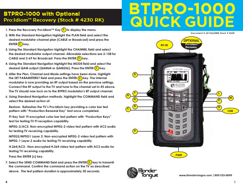
5. After the Plan, Channel and Mode settings have been done, highlight the SET PARAMETERS? field and press the ENTER C key. The internal modulator is now providing an RF output based on the previous settings. Connect the RF output to the TV and tune to the channel set in #3 above. The TV should now lock on to the BTPRO modulator’s RF output channel.
Functions Table
Main Function
Secondary Function (press and hold for 2s)
A Main switch (ON/OFF):
Level/Ch. Power meas. (press once)
RESET (press and hold for 10s)
MPEG2/MPEG1 Layer 2: Non-encrypted MPEG-2 video test pattern with MPEG-1 Layer 2 audio for testing TV receiving capability.
PT二次压降测试仪说明书
PT二次压降测试仪说明书由于输入输出端子、测试柱等均有可能带电压,在插拔测试线、电源插座时,会产生电火花,小心电击,避免触电危险,注意人身安全!安全要求请阅读下列安全注意事项,以免人身伤害,为了避免可能发生的危险,只可在规定的范围内使用。
只有合格的技术人员才可执行维修。
—防止火灾或人身伤害使用适当的电源线。
只可使用专用并且符合规格的电源线。
正确地连接和断开。
当测试导线与带电端子连接时,请勿随意连接或断开测试导线。
注意所有终端的额定值。
为了防止火灾或电击危险,请注意所有额定值和标记。
在进行连接之前,请阅读使用说明书,以便进一步了解有关额定值的信息。
使用适当的保险丝。
只可使用符合规定类型和额定值的保险丝。
避免接触裸露电路和带电金属。
有电时,请勿触摸裸露的接点和部位。
请勿在潮湿环境下操作。
请勿在易爆环境中操作。
-安全术语警告:警告字句指出可能造成人身伤亡的状况或做法。
目录一概述 (5)二主要特点 (5)三主要技术指标 (6)四工作原理 (7)五软件主要功能介绍 (7)六使用方法及注意事项 (10)七附一:检定方法 (21)一.概述电能计量综合误差过大是电能计量中普遍存在的一个关键问题,电能计量综合误差是由电压互感器的合成误差、电流互感器的合成误差、电度表的误差、电压互感器二次导线压降所引起的计量误差所组成。
在这四项误差中,电压互感器二次导线压降引起的计量误差往往是最大的。
电能计量装置检定规程《SD109-83》和有关技术法规,对电压互感器二次回路压降引起的误差均有规定,必须准确、快速、方便、可靠地测量出来。
电压互感器二次回路压降包括电缆、端子接触电阻、熔线、中间继电器接点、空气小开关等电压降之总和。
所谓电压互感器二次电压降引起的误差,就是指电压互感器二次端子和负载端子之间电压的幅值差相对于二次实际电压的百分数,以及两个电压之间的相位差的总称。
电压互感器二次回路压降测量方法通常有间接测量法和直接测量法两种(无线测量属于间接测量法),由于间接测量法准确度不太高,不能满足测量要求,一般不采用此种方法,而直接测量法(校验仪测量法)采用测差原理,准确度高,测量可靠,因此在实际测量中大量采用。
02-新北洋产品介绍
混合打印扫描产品及专用扫描产品
身份证卡专用复印机及证卡扫描仪
BST-2008E/BSTBST-2008E/BST-2008ER
BSTBST-2008S
BSTBST-3100/3300
自助服务系统及设备
自助服务系统及设备 以公司的关键基础部件为基础, 以公司的关键基础部件为基础,为各新兴领域提供自 助识别、查询、缴费、取单取卡、 助识别、查询、缴费、取单取卡、展示等自助服务系 统及设备
收据/日志打印机
1、热敏收据/日志打印机 热敏收据/
(1)50mm热敏收据/日志打印机 50mm热敏收据/ 热敏收据
BTPBTPBTP-R356II/ BTP-N58
BTPBTP-R358
BTPBTP-N58II
收据/日志打印机
(2)80mm热敏收据/日志打印机 80mm热敏收据/ 热敏收据
BTPBTP-2002CP BTPBTP-98NP BTPBTP-R580
山东新北洋信息技术股份有限公司
Brief introduction of Shan Dong New Beiyang Information Technology Co., Ltd
2011.10
关键基础零部件
具有打印、扫描、磁读写、RFID读写 读写、 具有打印 、 扫描 、 磁读写 、 RFID 读写 、 货币和支票识别 等功能, 等功能,可作为关键基础零部件嵌入到整机设备
主要包括:高速铁路售检票设备、通信自助服务、交通处罚自助查询缴费、 主要包括:高速铁路售检票设备、通信自助服务、交通处罚自助查询缴费、社保自助缴 费查询系统等各种新兴领域的自助服务系统及设备。 费查询系统等各种新兴领域的自助服务系统及设备。
自助服务系统及设备
BTP-1000PTII用户手册VER2

BTP-1000PTII标签打印机用户手册新北洋信息技术股份声明本手册容未经同意不得随意更改,新北洋信息技术股份(以下简称新北洋)保留在技术、零部件、软件和硬件上变更产品的权利。
用户如果需要与产品有关的进一步信息,可与新北洋或经销商联系。
未得到新北洋的书面许可,本手册的任何章节不得以任何形式、通过任何手段进行复制或传送。
本手册容如有任何变动,恕不另行通知。
本手册于2007年印制,属于新北洋。
中国印制。
2.0版本。
商标新北洋使用的注册商标是警告、注意警告必须遵守,以免伤害人体,损坏设备。
注意给出了打印机操作的重要信息及提示。
新北洋质量管理体系通过下列认证:挪威船级社(DNV)ISO9001:2000 认证本产品已通过下列认证:安全须知在操作使用打印机之前,请仔细阅读下面的注意事项。
➢安全警告警告:打印头为发热部件,打印过程中和打印刚结束不要触摸打印头以及周边部件。
警告:不要触摸打印头表面和连接插件,以免因静电损坏打印头。
➢注意事项1)打印机应安装在一个平整、稳固的地方;2)在打印机的周围留出足够的空间,以便操作和维护;3)打印机应远离水源并避免、强光和热源的直射;4)不要在高温、高湿以及污染严重的地方使用或保存打印机;5)避免将打印机放在有振动或冲击的地方;6)避免打印机表面结露,一旦形成,待露水消失后才可打开电源;7)将打印机的电源适配器连接到一个适当的接地插座上。
避免与大型电机或其它能够导致电源电压波动的设备使用同一插座;8)如果较长时间不使用打印机,请断开打印机电源;9)避免水或导电的物质(例如:金属)进入打印机部,一旦发生,应立即关闭电源;10)打印机不得在无纸状态下打印,否则将严重损害打印头和胶辊;11)连接/断开各接口时,必须关闭电源,避免打印机控制电路损坏;12)在打印效果满足使用要求的前提下,建议设置尽可能低等级的打印浓度,以提高打印头的使用寿命;13)在压下打印头组件前必须先压下压纸组件,否则不能正常打印;14)用户不得自行拆卸打印机进行检修。
PET1000N 电子式互感器校验仪使用说明书

本手册是北京博电新力电气股份有限公司的出版物。
任何形式的复制均需征得北京博电新力电气股份有限公司的同意。
本手册只代表出版时的技术动态。
手册中的产品信息、说明以及所有技术数据均不具有合同约束力。
北京博电新力电气股份有限公司保留随时对技术、配置进行修改而不另行通知的权利。
北京博电新力电气股份有限公司对本手册中可能发生的错误不承担责任。
目录1.产品概述 (5)1.1产品功能和特点 (5)1.2系统配置 (6)1.3面板说明 (7)1.3.1前面板 (7)1.3.2左面板71.3.3右面板 (8)2.技术参数 (9)2.1模拟量指标 (9)2.2数字输入电压 (9)2.3数字输入电流 (9)2.4通信接口 (9)2.5FT3信号参数 (10)2.6同步信号输入参数 (10)2.7同步信号输出参数 (10)2.8安全性能 (10)2.9环境条件与影响量 (10)2.10外壳与防护 (11)2.11机械参数 (11)3.测试软件 (12)3.1概述 (12)3.2程序主界面 (12)3.3工具栏使用说明 (14)3.4参数设置说明 (15)3.5小信号谐波输出功能说明 (20)3.6FT3输出功能说明 (20)4.测试过程说明 (22)4.1PET1000N校验系统框图 (22)4.2接线 (23)4.2.1信号源接线 (23)4.2.2被测互感器接线 (23)附录A装置可能出现的异常现象 (25)附录B互感器误差限值 (26)注意事项1.本仪器为高精度测试仪器,为保证测量精度,装置开机后建议预热10分钟以上再进行测试。
2.该仪器供电电源为交流220V(50Hz,5A),请勿将直流电压或交流380V电源接入到电源输入端,否则可能会造成仪器损坏。
3.外接笔记本电脑测试进行时,笔记本与测试仪通过以太网双绞信号线连接,应保证信号线可靠连接,不要随意拉扯信号线或晃动信号线连接端。
4.仪器配套的联机软件建议运行在Windows XP或Window7操作系统下。
SENTRONIC Brite-X 1000P 操作指南说明书
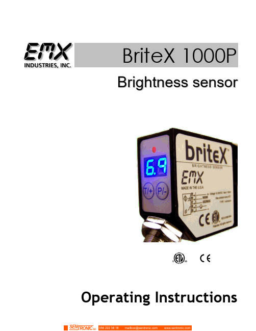
B r i t e X 1000PB r i g h t n e s s s e n s o rOperating InstructionsCAUTIONS AND WARNINGSWARNING:1.The Brite-X is not intended for use in personal safety applications.2.The Brite -X is not an explosion-proof enclosure. Do not use in an environment where flammable materials arepresent.3.The Brite -X sensor uses a high intensity, blue LED, do not look directly into this light source.CAUTION: The discrete output must not be connected to outputs from other sensors (i.e.outputs from multiple sensors must not be connected in parallel). Parallelconnections may damage sensor output circuitry.IMPORTANT:This product is an accessory or part of a system. Always read and follow the manufacturer’s instructions for the equipment before connecting this product. Comply with all applicable codes and safety regulations. Failure to do so may result in damage, injury or death.CERTIFICATIONS: CE, CSA, ULReg.# 9901994PRODUCT OVERVIEWBrite-X 1000P sensor was designed to measure the relative brightness of paper, board and pulps. The brightness is a reflectance factor of diffused blue light (457nm) as defined by ISO 2470. Brite-X 1000P uses a blue LED to emit modulated light that is projected on to a test surface. This light is then reflected back to the Brite-X 1000P optics and measured by the sensor software.The output is provided as an analog, 0 – 5 V signal with high, 20mV resolution. A PLC or a computer can process the analog output, or the reflected level can be set on the Brite-X 1000P to trigger a discrete output.The Brite-X 1000P is a compact sensor with a range of operation exceeding 36 inches. Two seven segment displays provide visual representation of the relative brightness from 00 to 99. The calibration feature, and 3 LED intensity settings provide for flexible operation over wide range of distances and materials.SpecificationsBlue Light source 457nm LED, min.100,000 hoursLED Intensity 3 levelsRelative Brightness Display Range 00 to 99Sensitivity AdjustableDetection Range Up to 36 inches (900mm)Switching Frequency 5 kHzBrightness level Two 7 segment digitsBrightness threshold Two 7 segment digitsAnalog Output 0 – 5 V (20mV resolution)Digital Output Auto-Detect PNP / NPNExtend Output Pulse 0 - 90 mS (10 steps)Output Function NO/NC selectableOn/Off Delay <150 uSDetect indicator Red LEDProgramming indicator Yellow LEDData retention EEPROM non—volatile memoryDimensions 2” (51mm) x 4” (100mm) x 1” (25mm)Weight .26 lbs. (117g)Supply Voltage 10…24 VDCOperating Current 60 mAShort Circuit Protection Yes (Outputs)Overload / Reverse Polarity Protection Yes (Supply Voltage)Operating temperature -20ºC…55ºCStorage temperature -20ºC…70ºCHousing Metal alloyMechanical protection IP65 NOT FOR PRESSURE WASHDOWNConnector M12 5 pinQUICK START GUIDE1.The display range is 00 through 99. The decimal points indicate the LED intensity level. The REDLED above the display indicates that the intensity level exceeds the threshold setting.2.Connect cable to power supply observing correct polarity. Reference wiring diagram.3.Apply power; sensor will initialize and perform its power up sequence.4.The relative intensity will be displayed. By aiming the sensor away from any objects the displaywill indicate 00. Aim the sensor at a white piece of paper and the display will indicate an intensity measurement. Move the paper further away from the sensor to decrease the intensity level.5.Various adjustments may be made to increase or decrease sensitivity; refer to the SectionsCalibration Adjustment and LED Intensity Level. Refer to Section: Threshold, to alter threshold setting.er programmable parameters are discussed in detail in the following sections.OperationPower upUpon power up, the sensor initializes by turning on all segments on the display and sequencing through red, amber and green on the status LED located above the display.Intensity display modeDuring normal operation the sensor display will indicate the relative intensity of a target its field of view. The range of the relative intensity display is 00 through 99. The decimal points on the display indicate the LED output intensity. No decimal points indicate low, one decimal point indicates medium and two decimal points indicate high intensity.Calibration AdjustmentThe calibration feature allows the displayed measurement to be adjusted to the desired value by the user.Adjusting the measured value:1.Place target in sensor’s field-of-view. The sensor will display the current reading.2.Press either key (for less than 3 seconds); while the current reading is displayed the valueis flashed slowly indicating that the sensor is in the adjustment mode.3.Press T/+ to increment the reading and P/- to decrement the reading.4.Stop pressing either key and sensor returns to normal operating mode in 3 seconds.Note:While adjusting the reading, when a limit is reached the display flashes at a faster rate.The selected gain is stored in memory and is retained when power is removed.Local LockThe local lock feature allows the sensor to be locked out, preventing adjustments by unauthorized personnel. To lock the sensor, press the P/- and T/+ buttons for 3 seconds until LL is displayed.To un-lock the sensor, press the T/+ and P/- for 3 seconds until LL is not displayed. While the sensor is locked, pressing either P/- or T/+ will result in LL (L ocal L ock) indication on the display.Programmable ParametersAll adjustments made to these parameters are stored in memory and are retained when power is removed. To enter programming mode press and hold the P/-key for several seconds, the current threshold setting will be displayed. Press and release the P/- key to scroll through the various settings. Press and release the T/+ key to change a particular setting. Press and hold the P/- for several seconds to return to the normal intensity display mode. The user programmable items are described below.ThresholdWhen the relative intensity level exceeds the threshold setting the red status LED will turn on and the discrete output will activate, indicating detection of the target. When the relative intensity level drops below the threshold (as determined by the hysteresis setting), the red LED will extinguish and the discrete output will de-activate. The threshold setting allows the user to select the detection level. The default setting is 15.To adjust the threshold, enter programming mode, press and hold the P/- key for several seconds, the current threshold setting will be displayed. Press and release the T/+ key to increase the threshold level, to decrease the threshold level, continue to hold the T/+ key until the value approaches 99 then wraps around to 00.LED Intensity Level (U)The LED intensity is indicated on the display as U1, U2 and U3 for low, medium and high intensity.Press and release the T/+ key to toggle through the 3 intensity levels.The default setting is U2, medium intensity.Hysteresis Level (H)The hysteresis setting is indicated by H0 through H9. The hysteresis level is how far below the threshold the signal must fall to de-activate or un-detect. The hysteresis can be set from 0 to 9.For example, if the threshold is set at 25 and the intensity exceeds 25, the sensor will detect and activate its output. With the hysteresis set to 5, the signal must drop to 20 to un-detect. This feature is useful in cases where there may be variation within a target that might cause the intensity to drop below the threshold slightly; the hysteresis allows the output to remain activated until the level drops significantly. Press and release the T/+ key to change the hysteresis setting.The default setting is 2.Discrete Output ConfigurationThis setting allows the user to select either normal open (no) or normally closed (nc) configuration. The normally open configuration de-activates the output during normal un-detect operation, and activates the output upon detect. The normally closed configuration activates the output during normal un-detect operation, and de-activates the output upon detect. Press and release the T/+ key to toggle through the selections. Default is normally open.Extend Output Pulse (P)This feature allows extending the minimum length of time that the discrete output remains active following target detection. The sensor response can be in the 100uS (microsecond) range, i.e. a target can move through the sensing range in 100uS and the discrete output would active for only that duration. A slower acquisition system (PLC) may not sample its inputs at a fast enough rate to capture the signal. The discrete output pulse can be extended from 0 to 90mS (milliseconds) in10 mS increments as indicated by P0 though P9 on the display. Press and release the T/+ key totoggle through the selections.Null Offset (nu)The null feature allows the sensor to be “zeroed”. For example, when the target is not in view and there is a background that causes a reading above zero, the null feature allows this level to be subtracted out, allowing the display to indicate 00. Press and hold the T/+ key to null the sensor. The display will flash the value that is being subtracted. To set the sensor back to a true zero, aim the sensor away from any target and repeat the null process.Output SignalsDiscrete OutputThe discrete output is a PNP/NPN configuration allowing the user to provide a load on this output that is either pulled high to VDC or low to ground. The sensor monitors this level and automatically determines whether to operate the PNP/NPN driver. This output is typically connected to a PLC. The output remains active as long as the intensity level exceeds the threshold, in high-speed applications it may be useful to use the Extend Output Pulse feature to lengthen the signal duration to meet acquisition requirements of the PLC.CAUTION: The discrete output must not be connected to outputs from other sensors (i.e.outputs from multiple sensors must not be connected in parallel). Parallelconnections may damage sensor output circuitry.Analog OutputThe analog output is 0-5V with 20mV resolution (8-bit). Any standard analog input channel typically available on a PLC may monitor this output. The analog output signal is useful in applications where simply triggering on the threshold is insufficient. For example, constant real-time monitoring of intensity in process allows minor fluctuations or trends to be detected permitting corrective action to be taken. In applications where minor differences in color are to be detected, variations in brightness producing discernable level changes in the analog output can be used to differentiate between similar colors.Remote Lock/Unlock InputThe remote lock feature allows the user to lock out the local controls (keys) to prevent operators from making unauthorized adjustments. This signal line must be connected to VDC to lock the sensor. This line may be left unconnected if the lock feature is not used. While the sensor is locked, pressing either P/- or T/+ will result in rL (r emote L ock) indication on the display.Display IndicatorsIndicatorsGreen LED Red LED DetectYellow LEDDisplay decimal pointsNone illuminated LED low intensity Two illuminated LED high intensityM12 connector pin assignmentsOrdering informationBrite-X 1000PBrightness sensor, 457nmAccessoriesUVX300-BRKT UVX 300-CBracket5-meter cable with M12 5 pin connectorDimensional Details4.00(100.0 mm)0.0000.6250.1500.6508-32 UNC0.800(20.3 mm)Warranty。
AP1000技术手册-PT2
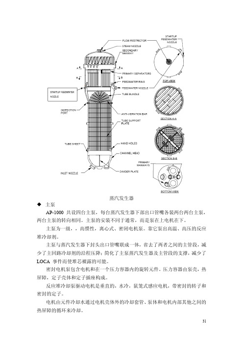
蒸汽发生器主泵AP-1000 共设四台主泵,每台蒸汽发生器下部出口管嘴各装两台两台主泵,两台主泵的转向相同。
主泵的安装不同于通常,而是泵在上电机在下。
主泵为一级,,高惯性,离心式、密闭电机泵。
靠它泵出高温、高压的反应堆冷却剂。
主泵与蒸汽发生器下封头出口管嘴联成一体,省去了两者之间的主管段,减少了主回路冷却剂的沿程压降;简化了主泵蒸汽发生器及主管段的支撑,减少了LOCA 事件而使堆芯裸露的可能。
密封电机泵包含电机和在一个压力容器内的旋转元件。
压力容器由泵壳,热屏障,定子壳体和定子插座构成。
反应堆冷却泵驱动电机是垂直的,水冷,鼠笼式感应电机,带密封的转子和密封的定子。
电机由元件冷却水通过电机壳体外的冷却套管、泵体和电机内部其他之间的热屏障的循环来冷却。
泵电机由可变速驱动器驱动。
可变速驱动器由隔离变压器、电力转换器、冷却系统和控制系统组成。
泵装有振动检测系统来检测泵结构的振动。
四个电阻温度探测器检测冷却循环水的温度。
传感器检测转子的转向和速度。
此外,电压,电流传感器提供电机负荷和输入电。
主泵布置图主冷却剂管道主冷却剂管道包括连接压力容器,蒸汽发生器、主泵的热端和冷端管段。
为双回路布置,每个回路有一条31英寸内径的热段将冷却剂运到蒸发器,和两条22英寸内径的冷段将冷却剂运回压力容器,完成一个循环。
蒸汽发生器/主泵的竖向支撑与蒸汽发生器的下封头相联并生根在平台上。
蒸汽发生器下封头采用一体锻制而成。
主泵吸入口焊在蒸汽发生器下封头底部的出口上,省去了与冷却剂回路的连管从而避免了潜在的在小LOCA 后,回路密封放气而致的堆芯裸露风险。
此外还减少了阻尼器,防甩装置。
RCS管道也包括连接到主管道和主要元件的管道。
RCS的边界包括到两个隔离阀或关闭阀中的第二个阀以及之间管道。
紧凑而简化的布置还带来另外一些好处。
每条回路中的两条冷段所带的弯管减少了流动阻力以及因冷热段胀差而引起的应力。
管道先扎制成直段而后通过感应加热成型工艺制成弯管。
btp2000TG维护手册
强烈建议一. 打印机的联接1.必须保证打印机可靠接地。
2.关闭打印机和计算机,按要求将打印机和计算机用通讯电缆联接。
3.严禁在打印机和计算机未关闭的情况下带电插拔通讯电缆。
4.保证打印机电源线和打印机电源插座联接紧密。
5.保证通讯电缆线和计算机、打印机联接紧密。
二. 打印机的开机1.首次使用打印机前,请使用纸张校准功能。
(参照第三章3.5节)2.由于各种票纸的不一致性,为避免废票的出现,正式打印前需由具有维护、维修资格的专业人员对驱动程序进行安装。
同时对票纸参数进行校准,打印机参数(切纸位置、上纸位置、首张位置、左右位置等)的设置予以确认。
(参照第三章3.3节)3.打印机和计算机的开启顺序是:先开打印机,再开计算机。
4.打印机的关机和开机的时间间隔不得少于20秒。
5.联机后,若由于某些原因使打印机关电,而计算机没有关闭,在售票前一定要重新初始化打印机,否则打印机将报警“指令语法错误”。
1.2 技术参数功能指标打印方式:热敏/热转印打印分辨率: 200 DPI有效打印宽度:104 mm打印速度: 125、100、80、60 mm/s打印范围: 104 mm ×108 mm出纸方式:连续出纸方式、自动切纸方式打印参数设置:打印浓度 -8 ~ +7切纸位置 -32 ~ +31上纸位置 -32 ~ +31首张位置 -32 ~ +31左右位置 -32 ~ +31打印字符种类:ASCⅡ字符、Times New Roman 字符、 OCRB字符、外加图形(最多512个)打印条码种类:128码、PDF417码打印纸规格:最大宽度 110mm最大外径 180mm标准纸卷内径 50mm厚度 0.065~0.2mm热转印碳带:温度范围 +65~+80℃最大外径 65mm标准碳带卷内径 25mm类型石蜡系列、树脂系列厚度 5.7±0.5µm/4.5±0.5µm带基材料聚脂薄膜外形尺寸: 275mm(H)×235mm(W)×380mm(D) 重量: 13kg电气指标电源电压: AC 176V - 264V频率: 50/60Hz功率:待机时 25 VA最大 270VA对地漏电流:小于 3.5mA耐电强度:电源插头与机壳间承受50Hz、 1500V交流电历时1分钟无击穿、飞弧现象。
TBS1000 用户手册介绍

TBS1000 系列 数字存储示波器
ZZZ
用户手册
*P077076700*
077-0767-00
xx
TBS1000 系列
数字存储示波器
ZZZ
用户手册
077-0767-00
Copyright © Tektronix. 保留所有权利。许可软件产品由 Tektronix、其子公司或提供商所有,受国 家版权法及国际条约规定的保护。
本保证声明不适用于由于使用不当或者维护保养不当或不足所造成的任何缺陷、故障或损坏。 Tektronix 在本保证声明下没有义务提供以下服务:a) 修理由非 Tektronix 服务代表人员对产品进行安装、修理 或维护所导致的损坏;b) 修理由于使用不当或与不兼容的设备连接造成的损坏;c) 修理由于使用非 Tektronix 提供的电源而造成的任何损坏或故障;d) 维修已改动或者与其他产品集成的产品(如果这 种改动或集成会增加产品维修的时间或难度)。
本保证由 TEKTRONIX 关于本产品而订立,用于替代任何其他的明示或暗示的保证。 TEKTRONIX 及其供 应商拒绝对用于特殊目的的适销性或适用性做任何暗示的保证。 对于违反本保证的情况,TEKTRONIX 负责修理或更换有缺陷产品是提供给客户的唯一和独有的补救措施。 无论 TEKTRONIX 及其供应商是否 被预先告知可能发生任何间接、特殊、意外或引发的损坏,TEKTRONIX 及其供应商对这些损坏都不负有 责任。
[W19 – 03AUG12]
TPP0101 和 TPP0201 探头
保修
Tektronix 保证本产品自发货之日起一年内,不会出现材料和工艺方面的缺陷。如果在保修期内证实任 何此类产品有缺陷,Tektronix 将自主决定,是修复有缺陷的产品(但不收取部件和人工费用)还是提 供替换件以换回有缺陷的产品。Tektronix 在保修工作中使用的部件、模块和替代产品可能是新的,也 可能是具同等性能的翻新件。所有更换的部件、模块和产品均归 Tektronix 所有。
Philips 1000系EN用户手册说明书
1000 series235 sec.413460 min.PhilipsPenguap Kain GenggamSTH1000220-240V~, 50-60Hz, 820-980W Diimpor oleh:PT Philips Domestic Appliances Indonesia CommercialGedung Cibis Nine Lantai 10Jl. T.B. Simatupang No. 2 RT. 001 RW. 005 Kel. Cilandak Timur, Kec. Pasar Minggu Jakarta Selatan 12560 – Indonesia Negara Pembuat: CinaApplicable for Indonesia only設備名稱:飛利浦手持式蒸汽掛燙機型號(型式):STH1000 Equipment name: Type designation (Type):單元Unit限用物質及其化學符號鉛Lead(Pb)汞Mercury(Hg)鎘Cadmium(Cd)六價鉻Hexavalentchromium(Cr)多溴聯苯Polybrominatedbiphenyls(PBB)多溴二苯醚Polybrominateddiphenyl ethers(PBDE)電源線組O O O O O O上蓋O O O O O O主體O O O O O O水箱O O O O O O加熱元件O O O O O O備考1. “超出0.1 wt %”及“超出 0.01 wt %”係指限用物質之百分比含量超出百分比含量基準值。
Note 1:“Exceeding 0.1 wt %” and “exceeding 0.01 wt %” indicate that the percentage content of the restricted substance exceeds the reference percentage value of presence condition.備考2. “○”係指該項限用物質之百分比含量未超出百分比含量基準值。
- 1、下载文档前请自行甄别文档内容的完整性,平台不提供额外的编辑、内容补充、找答案等附加服务。
- 2、"仅部分预览"的文档,不可在线预览部分如存在完整性等问题,可反馈申请退款(可完整预览的文档不适用该条件!)。
- 3、如文档侵犯您的权益,请联系客服反馈,我们会尽快为您处理(人工客服工作时间:9:00-18:30)。
BTP-1000PTII用户手册VER2BTP-1000PTII标签打印机用户手册山东新北洋信息技术股份有限公司声明本手册内容未经同意不得随意更改,山东新北洋信息技术股份有限公司(以下简称新北洋)保留在技术、零部件、软件和硬件上变更产品的权利。
用户如果需要与产品有关的进一步信息,可与新北洋或经销商联系。
未得到新北洋的书面许可,本手册的任何章节不得以任何形式、通过任何手段进行复制或传送。
本手册内容如有任何变动,恕不另行通知。
版权本手册于2007年印制,版权属于新北洋。
中国印制。
2.0版本。
商标新北洋使用的注册商标是警告、注意警告必须遵守,以免伤害人体,损坏设备。
注意给出了打印机操作的重要信息及提示。
新北洋质量管理体系通过下列认证:挪威船级社(DNV)ISO9001:2000 认证本产品已通过下列认证:安全须知在操作使用打印机之前,请仔细阅读下面的注意事项。
➢安全警告警告:打印头为发热部件,打印过程中和打印刚结束不要触摸打印头以及周边部件。
警告:不要触摸打印头表面和连接插件,以免因静电损坏打印头。
➢注意事项1)打印机应安装在一个平整、稳固的地方;2)在打印机的周围留出足够的空间,以便操作和维护;3)打印机应远离水源并避免阳光、强光和热源的直射;4)不要在高温、高湿以及污染严重的地方使用或保存打印机;5)避免将打印机放在有振动或冲击的地方;6)避免打印机表面结露,一旦形成,待露水消失后才可打开电源;7)将打印机的电源适配器连接到一个适当的接地插座上。
避免与大型电机或其它能够导致电源电压波动的设备使用同一插座;8)如果较长时间不使用打印机,请断开打印机电源;9)避免水或导电的物质(例如:金属)进入打印机内部,一旦发生,应立即关闭电源;10)打印机不得在无纸状态下打印,否则将严重损害打印头和胶辊;11)连接/断开各接口时,必须关闭电源,避免打印机控制电路损坏;12)在打印效果满足使用要求的前提下,建议设置尽可能低等级的打印浓度,以提高打印头的使用寿命;13)在压下打印头组件前必须先压下压纸组件,否则不能正常打印;14)用户不得自行拆卸打印机进行检修。
目录1概述 (1)1.1简介 (1)1.2主要特点 (1)2主要技术指标 (2)2.1主要技术规格 (2)2.2介质技术规格 (3)3外观和组件 (3)3.1外观和组件 (3)3.2主要组件功能介绍 (5)3.3电源、告警指示灯和蜂鸣器 (6)4打印机的安装 (8)4.1打印机开箱 (8)4.2连接AC电源适配器 (8)4.3连接接口电缆 (8)4.4纸卷的安装 (8)4.5碳带的安装 (10)5打印机的启动 (12)5.1打印机开机与自检 (12)5.2打印方式的选择 (12)5.3打印机校验 (12)5.4打印自检样张 (13)5.5打印机常用参数的调整 (14)5.6透射传感器位置调整 (17)6打印机的日常维护 (18)6.1打印头清洁 (18)6.2传感器清洁 (18)6.3打印胶辊清洁 (19)7常见故障处理方法与维护 (20)附录 (21)附录1打印机配置信息 (21)附录2介质的技术规格 (26)附录3接口说明 (29)1概述1.1简介BTP-1000PTII标签打印机采用模块化设计,具有结构简单、操作方便等特点,可广泛适用于交通、邮政、商业物流等领域。
BTP-1000PTII标签打印机可以通过标准并行接口或串行接口与其他设备连接,同时提供WINDOWS95 /98/2000/NT4.0/XP操作系统下的通用驱动程序及基于DLL的软件开发包。
1.2主要特点➢热敏/热转印打印➢Easy-Media-Loading结构设计,操作简便、舒适➢模块化设计,满足不同的应用需求➢温度自适应控制2主要技术指标2.1主要技术规格项目参数物理特性外形尺寸235 mm (W)×364 mm (D)×238 mm (H)重量约9Kg2.2介质技术规格本打印机支持连续纸和非连续纸两种纸张类型。
➢连续纸类型包括:无黏合剂条状卷筒纸➢非连续纸类型包括:●无黏合剂标记卷筒纸●无黏合剂穿孔卷筒纸各类介质的技术规格详见附录2。
3外观和组件3.1外观和组件图3.1.1 图3.1.21—电源开关2—电源插孔3—标准并口插座4—9针RS-232串行接口插座5—按键6—电源(告警)指示灯7—出纸通道8—打印机上盖9—碳带压力调整旋钮10—碳带发放轴11—碳带回收轴图3.1.3 图3.1.412—碳带传感器13—打印头组件14—左侧逼纸块15—右侧逼纸块16—打印头组件扳手17—压纸组件扳手18—压纸组件19—纸卷支撑架组件20—打印头微动开关21—前逼纸块22—透射传感器23—定位柱224—定位柱1 25—调节旋钮26—打印胶辊3.2主要组件功能介绍A----电源开关(1)按下“O”关闭电源,按下“|”开启电源;B----按键(5)➢进纸按键功能●按住进纸按键并打开电源开关,与电源指示灯配合功能如下表:指示灯/按键状态按键功能指示灯闪烁一次松开按键打印配置样张指示灯连闪两次松开按键校验纸张恢复默认通讯(9600,N,8,1,硬握手,无自指示灯连闪三次松开按键动上纸)关机不保存●其它状态下进纸按键功能✧打印机待机状态下按此键:打印机前进一个票面;✧打印机出错状态下按此键:排除打印机错误,恢复打印机到待机状态;✧撕离模式打印时电源指示灯将闪烁,等待用户按下进纸按键确认打印此票面,此时按此键,打印机将退纸到打印头下并开始打印。
➢暂停按键功能打印过程中按下此键,打印机进入暂停状态,此时可以抬起打印头,调整介质位置或更换介质,按下并锁紧打印头,再按下暂停按键,打印机继续打印。
C----电源(告警)指示灯(6)检测电源的开关状态和反映打印机是否处于正常的状态;D----碳带传感器(12)探测打印机碳带的存在状态;E----逼纸块(14,15,21)将介质夹在逼纸块之间,防止介质在通道中左右滑动,否则打印机将无法正常判别介质状态;F----压纸组件(18)减轻介质在出纸通道中上下波动,以免造成打印机定位不准确。
G----打印头微动开关(20):检测打印头位置(抬起/压下)状态;H----纸标记传感器包括透射传感器(22)和反射传感器,反射传感器位于前逼纸块(21)下面,距通道左边缘5mm,用于检测介质的存在状态及标记。
3.3电源、告警指示灯和蜂鸣器3.3.1电源和告警指示灯状态功能表指示灯名称状态说明电源指示灯(绿色)常亮打印处于开机正常状态快闪打印机忙慢闪在线升级监控程序出错指示灯(红色)灭打印机正常状态常亮暂停状态闪烁出错报警3.3.2告警指示灯和蜂鸣器状态功能1)蜂鸣器短鸣:打印机在开机或复位正确时,蜂鸣器短鸣一声;2)打印机错误信息与蜂鸣器鸣叫、指示灯闪烁对照表:错误信息蜂鸣器鸣叫/错误灯闪烁打印头抬起指令语法错误打印机缺纸串口通讯错误纸张检验错误打印头电压/温度异常打印机缺碳带打印机切刀错打印机碳带将尽系统错误4打印机的安装4.1打印机开箱打开打印机包装,对照装箱单检查物品是否缺少或损坏。
如果出现物品缺少或损坏现象,请立即与经销商联系。
4.2连接AC电源适配器1)确认打印机的电源开关处于关闭状态;2)将电源适配器电缆插头平直的一面向上,插入打印机侧面的电源接口内;3)接通电源适配器的输入电源。
注意:⏹应采用厂家推荐的电源适配器或等同产品;⏹插拔电源适配器插头时,应手持插头的连接器外壳,不要用力拉拔电缆;⏹避免拖动电源适配器的电缆,否则会损坏电缆,引起火灾和电击;⏹避免将电源适配器放置在过热的设备周围,防止电缆表面融化,引起火灾和电击;⏹如果较长时间不使用打印机,请断开打印机电源适配器的电源。
4.3连接接口电缆1)确认打印机的电源开关处于关闭状态;2)将接口电缆插入相配的接口内,并用插头的螺丝钉或卡簧固定;3)将接口电缆的另一端连接到主机上。
注意:请勿带电插拔接口电缆!4.4纸卷的安装4.4.1打印介质类型的确认介质安装前首先应确认打印机使用的纸张类型。
默认的纸张类型为袋牌纸,如果采用其它类型的打印纸张,应首先通过指令集中的命令设置相应纸张类型。
设置方法参见《条码打印机编程手册》。
4.4.2安装打印纸卷1)打开打印机的上盖;2)如图4.1所示,依次抬起打印头组件、压纸组件;3)如图4.2所示,将纸卷装在支撑杆上,两侧安装逼纸板,然后装在支撑架中;4)按图4.3所示,将纸张夹在两个逼纸块之间,调整逼纸块,使其距纸张的间隙不超过1mm;图4.1 图4.2 图4.3 图4.45)将纸前端放在打印胶辊上;6)如图4.4所示,确认纸正确地安装在通道内后,依次压下压纸组件、打印头组件;7)合上打印机上盖。
注意:⏹纸的打印面应朝上,若为黑标记纸,请将黑标记朝下;⏹打印头组件及压纸组件必须锁紧可靠,否则会影响打印机的正常工作;⏹装纸前,应确认纸张符合下图正确的要求:4.4.3 清除塞纸依次打开打印机上盖、打印头组件、压纸组件,沿走纸通道清除塞纸。
4.5 碳带的安装1) 按如图4.5所示,确定碳带内、外置方式后,将碳带装入碳带发放芯轴上;图4.52) 按图4.6所示将碳带发放轴与碳带压力调整旋钮内侧的前端配合在一起;图4.63) 压下碳带发放轴的另一侧,使其卡入右侧锁紧槽内; 4) 将空的碳带芯轴装到碳带回收轴上,并装配到相应的位置;5) 如图4.7所示抬起打印头组件,将碳带从打印头组件下面绕过并拉向碳带回收轴;6) 按图4.8所示将碳带头用胶带粘贴在碳带芯轴上,并旋转压力调整旋钮使其缠绕数圈;外置碳带的安装 内置碳带的安装图4.7 图4.87)旋转碳带压力调整旋钮,将碳带呈平整的绷紧状态。
注意:⏹确定打印方式:选择热转印方式,需要安装碳带;选择热敏方式,不需要安装碳带;⏹正常情况下,选用碳带应宽于打印介质的宽度;⏹安装碳带过程中应防止碳带起皱或破损。
5打印机的启动5.1打印机开机与自检1)确认电源线和通讯线已正确连接,打开打印机电源开关;2)打印机自检(初始化),初始化完毕后,蜂鸣器鸣叫一声;3)当蜂鸣器鸣叫一声后,打印机自检结束;非连续型介质且打印机允许自动上纸,打印机会自动上纸到打印位置。
注意:若打印机不能启动或启动后不能正常工作,请及时与经销商联系。
5.2打印方式的选择用户可根据介质的类型,确认打印方式和纸标记传感器类型。
打印机默认的打印方式是热转印方式;默认的纸标记传感器类型是透射传感器。
打印方式的设置方法参见《条码打印机编程手册》。
注意:应根据不同的纸张类型选择正确的打印方式。
5.3打印机校验➢手动校验功能1)关闭打印机;2)将介质安装好;3)按住进纸键不放,将电源开关扳至“|”位置,当电源指示灯连续闪烁两次后,松开进纸键,打印机进纸并校验标记;4)如果在校验后,打印机报警,说明校验失败,请查找:●介质安装是否正确;●安装介质类型与打印机设置介质类型是否一致。
