UU简明使用手册
Texas Instruments SLUU068C 用户指南说明书

IMPORTANT NOTICETexas Instruments Incorporated and its subsidiaries (TI) reserve the right to make corrections, modifications, enhancements, improvements, and other changes to its products and services at any time and to discontinue any product or service without notice. Customers should obtain the latest relevant information before placing orders and should verify that such information is current and complete. All products are sold subject to TI’s terms and conditions of sale supplied at the time of order acknowledgment.TI warrants performance of its hardware products to the specifications applicable at the time of sale in accordance with TI’s standard warranty. T esting and other quality control techniques are used to the extent TI deems necessary to support this warranty. Except where mandated by government requirements, testing of all parameters of each product is not necessarily performed.TI assumes no liability for applications assistance or customer product design. Customers are responsible for their products and applications using TI components. T o minimize the risks associated with customer products and applications, customers should provide adequate design and operating safeguards.TI does not warrant or represent that any license, either express or implied, is granted under any TI patent right, copyright, mask work right, or other TI intellectual property right relating to any combination, machine, or process in which TI products or services are used. Information published by TI regarding third−party products or services does not constitute a license from TI to use such products or services or a warranty or endorsement thereof. Use of such information may require a license from a third party under the patents or other intellectual property of the third party, or a license from TI under the patents or other intellectual property of TI.Reproduction of information in TI data books or data sheets is permissible only if reproduction is without alteration and is accompanied by all associated warranties, conditions, limitations, and notices. Reproduction of this information with alteration is an unfair and deceptive business practice. TI is not responsible or liable for such altered documentation.Resale of TI products or services with statements different from or beyond the parameters stated by TI for that product or service voids all express and any implied warranties for the associated TI product or service and is an unfair and deceptive business practice. TI is not responsible or liable for any such statements.Mailing Address:Texas InstrumentsPost Office Box 655303Dallas, Texas 75265Copyright 2001, Texas Instruments IncorporatedEVM IMPORTANT NOTICETexas Instruments (TI) provides the enclosed product(s) under the following conditions:This evaluation kit being sold by TI is intended for use for ENGINEERING DEVELOPMENT OR EVALUATION PURPOSES ONLY and is not considered by TI to be fit for commercial use. As such, the goods being provided may not be complete in terms of required design-, marketing-, and/or manufacturing-related protective considerations, including product safety measures typically found in the end product incorporating the goods. As a prototype, this product does not fall within the scope of the European Union directive on electromagnetic compatibility and therefore may not meet the technical requirements of the directive.Should this evaluation kit not meet the specifications indicated in the EVM User’s Guide, the kit may be returned within 30 days from the date of delivery for a full refund. THE FOREGOING WARRANTY IS THE EXCLUSIVE WARRANTY MADE BY SELLER TO BUYER AND IS IN LIEU OF ALL OTHER WARRANTIES, EXPRESSED, IMPLIED, OR STATUTORY, INCLUDING ANY WARRANTY OF MERCHANTABILITY OR FITNESS FOR ANY PARTICULAR PURPOSE.The user assumes all responsibility and liability for proper and safe handling of the goods. Further, the user indemnifies TI from all claims arising from the handling or use of the goods. Please be aware that the products received may not be regulatory compliant or agency certified (FCC, UL, CE, etc.). Due to the open construction of the product, it is the user’s responsibility to take any and all appropriate precautions with regard to electrostatic discharge.EXCEPT TO THE EXTENT OF THE INDEMNITY SET FORTH ABOVE, NEITHER PARTY SHALL BE LIABLE TO THE OTHER FOR ANY INDIRECT, SPECIAL, INCIDENTAL, OR CONSEQUENTIAL DAMAGES.TI currently deals with a variety of customers for products, and therefore our arrangement with the user is not exclusive.TI assumes no liability for applications assistance, customer product design, software performance, or infringement of patents or services described herein.Please read the EVM User’s Guide and, specifically, the EVM Warnings and Restrictions notice in the EVM User’s Guide prior to handling the product. This notice contains important safety information about temperatures and voltages. For further safety concerns, please contact the TI application engineer.Persons handling the product must have electronics training and observe good laboratory practice standards. No license is granted under any patent right or other intellectual property right of TI covering or relating to any machine, process, or combination in which such TI products or services might be or are used.Mailing Address:Texas InstrumentsPost Office Box 655303Dallas, Texas 75265Copyright 2001, Texas Instruments IncorporatedEVM WARNINGS AND RESTRICTIONSIt is important to operate this EVM within the input voltage range of 85 V to 265 V and the output voltage of 12 V +/− 5%.Exceeding the specified input range may cause unexpected operation and/or irreversible damage to the EVM. If there are questions concerning the input range, please contact a TI field representative prior to connecting the input power.Applying loads outside of the specified output range may result in unintended operation and/or possible permanent damage to the EVM. Please consult the EVM User’s Guide prior to connecting any load to the EVM output. If there is uncertainty as to the load specification, please contact a TI field representative.During normal operation, some circuit components may have case temperatures greater than 50°C. The EVM is designed to operate properly with certain components above 50°C as long as the input and output ranges are maintained. These components include but are not limited to linear regulators, switching transistors, pass transistors, and current sense resistors. These types of devices can be identified using the EVM schematic located in the EVM User’s Guide. When placing measurement probes near these devices during operation, please be aware that these devices may be very warm to the touch.Mailing Address:Texas InstrumentsPost Office Box 655303Dallas, Texas 75265Copyright 2001, Texas Instruments IncorporatedContentsContents. . . . . . . . . . . . . . . . . . . . . . . . . . . . . . . . . . . . . . . . . . . . . . . . . . . . . . . . . . . . .1General Information1-1 . . . . . . . . . . . . . . . . . . . . . . . . . . . . . . . . . . . . . . . . . . . . . . . . . . . . . . . . . . . . . . . . . .1.1Features1-2. . . . . . . . . . . . . . . . . . . . . . . . . . . . . . . . . . . . . . . . . . . . . . . . . . . . . . . . . . . . . . . .1.2Description1-2. . . . . . . . . . . . . . . . . . . . . . . . . . . . . . . . . . . . . . . . . . . . . . . . . . . . . . . .1.3Operating Guidelines1-3. . . . . . . . . . . . . . . . . . . . . . . . . . . . . . . . . . . . . . . . . . . .1.3.1Step 1. Load Connections1-3. . . . . . . . . . . . . . . . . . . . . . . . . . . . . . . . . . . . . . . . .1.3.2Step2. Applying Input Power1-3. . . . . . . . . . . . .1.3.3Step 3. Evaluating the Demonstration’s Boards Performance.1-3. . . . . . . . . . . . . . . . . . . . . . . . . . . . . . . . . . . . . . . . . . . . . . . .1.3.4Additional Information1-3. . . . . . . . . . . . . . . . . . . . . . . . . . . . . . . . . . . . . . . . . . . . . . . . .1.4DM38500 EVM Performance1-5. . . . . . . . . . . . . . . . . . . . . . . . . . . . . . . . . . . . . . . . . . . . . . . . . . . . . . . . . . . . . . . . . . . . . . .2Reference2-1. . . . . . . . . . . . . . . . . . . . . . . . . . . . . . . . . . . . . . . . . . . . .2.1DM38500 EVM Part Descriptions2-2. . . . . . . . . . . . . . . . . . . . . . . . . . . . . . . . . . . . . . . . . . . . . . . . . . . .2.2DM38500 Board Layouts2-4Figures. . . . . . . . . . . . . . . . . . . . . . . . . . . .1−1.DM38500 Evaluation Module Application Schematic1-4. . . . . . . . . . . . . . . . . . . . . . . . . . . . . . . . . . . . . .1−2.DM38500 EVM Response, VCC = +15 V1-5. . . . . . . . . . . . . . . . . . . . . . . . . . . . . . . . . . . . . . . . . . .1−3.DM38500 Response, VCC = +15 V1-5. . . . . . . . . . . . . . . . . . . . . . . . . . . . . . . . . . . . . . . . . . .1−4.DM38500 Response, VCC = +15 V1-6. . . . . . . . . . . . . . . . . . . . . . . . . . . . . . . . . . . . . .2−1.DM38500 EVM PC Board: Top Assembly2-4Chapter 1GeneralInformationThis chapter details the Texas Instruments (TI) DM38500 PFC/PWM Combination Controller 100W Power Factor Correction Preregulator Evaluation Module (EVM) SLUU068. It includes a list of EVM features, a brief description of the module illustrated with a pictorial, schematic diagrams, and EVM specifications.Topic Page . . . . . . . . . . . . . . . . . . . . . . . . . . . . . . . . . . . . . . . . . . . . . . . . . . . . .1.1Features1−2. . . . . . . . . . . . . . . . . . . . . . . . . . . . . . . . . . . . . . . . . . . . . . . . . . .1.2Description1−2 1.3Operating Guidelines1−3. . . . . . . . . . . . . . . . . . . . . . . . . . . . . . . . . . . . . . . . . .1.4DM38500 EVM Performance1−5. . . . . . . . . . . . . . . . . . . . . . . . . . . . . . . . . . . .General Information1-1Features1.1FeaturesUCC38500 PFC/PWM Combination Controller 100W Power Factor Correc-tion Preregulator include:J Combines PFC and 2nd Stage Down Converter ControlsJ Controls Boost Preregulator to Near-unity Power FactorJ Accurate Power LimitingJ Improved Feedforward Line RegulationJ Peak Current Mode Control in Second StageJ Programmable OscillatorJ Leading Edge/Trailing Edge Modulation for Reduced Output RippleJ Low Startup Supply CurrentJ Synchronized Second Stage with Programmable Soft-startJ Programmable Second Stage Shut-down1.2DescriptionThe UCC38500 provides all the functions necessary for active power factorcorrection and a second stage dc-to-dc converter all in one integrated circuit.The control IC uses leading edge modulation for the boost stage and trailingedge modulation for the step down converter to reduce the RMS current in theboost capacitor. The dc-to-dc controller uses peak current mode control foreasy loop compensation.The UCC38500 evaluation board is designed to illustrate the performance ofthe IC in a complete off-line 100W two-stage power converter using power fac-tor correction. The demonstration board was designed to operate with a uni-versal input voltage range (i.e. 85−265 Vac) with a regulated 12V dc output.CautionHigh-voltage levels are present on the evaluation module whenever it isenergized. Proper precautions must be taken when working with theEVM. The output capacitor has high levels of energy storage and it mustbe discharged before the load is removed. Serious injury can occur ifproper safety precautions are not followed.1-2Description1-3General Information 1.3Operating GuidelinesThe operating guidelines for the evaluation board are provided with reference to the schematic in Figure 1−1 and the component layout in Figure 2−1.1.3.1Step 1. Load ConnectionsA resistive or electronic load can be applied to the output terminals labeled OUT− and OUT+.Note: For safety reasons the load should be connected before power is sup-plied to the demonstration board.1.3.2Step2. Applying Input PowerA 60 Hz AC power source not exceeding 265 V RMS needs be applied across terminals AC−N and AC−L for proper operation.1.3.3Step 3. Evaluating the Demonstration’s Boards Performance.With the AC source set between 85−265 V RMS the output voltage should be regulated and the input current should track the input voltage shape with near unity power factor. The operation of the circuit is verified over the line and load range and shows efficiency as high as 85%. At lighter loads, there may be some distortion in the line current due to Discontinuous Conduction Mode (DCM) operation. Please refer to Figures 1−2, 1−3 and 1−4 for typical EVM performance.1.3.4Additional InformationFor more information, pin description and specifications for the UCC38500PFC/PWM Combination Controller, please refer to the datasheet or contact the Texas Instruments Semiconductor Product Information Center at 1-800-336-5236 or 1-972-644-5580. Product Information can also be found on the World Wide Web at .Description1-4Figure 1−1.DM38500 Evaluation Module Application SchematicUDG−000941210952611137843116171518191420O V P /E N B L V S E N S E V A O U T I S E N S E M O U TC A O U T I A C V F FP K L I M I T V R E F G T 1G T 2V C C C T R T G N D P W R G N D S S 2V E R R I S E N S E 2U C C 38500V R E FQ 5R 25V C CR 7R 6G T 1G T 2D 10D 9C 27P K L I M I TC 28R 17C 19C 22R 28C 25R 23R 34R 21R 22R 33R 20C 2R 15R 5L 1D 3D 1G T 1R 14R 29P K L I M I TR 19C 26V R E F R 18R 24C 29C 30I S E N S E 2G T 2R 13R 2C 5P W R G N D G T 212 V 100 W +−L 2T 1Q 2Q 1Q 3D 11V A C 85−265V R M SD 6D 4T 2D 8U 4C 7S G N DS G N D S G N DP G N D 2P G N DP G N DP G N DP G N DS G N D P G N D D 5D 7C 12C 20L 1V C C B I A S C I R C U I TV C CV C C B I A S C I R C U I TP G N D C 23P G N D 2P G N D 2R 26D 14R 36R 16C 14R 35R 32R 27D 13R 31C 8R 30R 10R 12R 11C 21C 16C 3P G N D C 24D 2R 1C 4C 18R 4D 15D 12D 16A C −NA C −LO U T +O U T −V R E FR 3R 39C 13I S E N S E 2C 17H 11A V 1321456U 3S G N D C 6C 38H I G H V O L T A G E −S E E E V M W A R N I N G S A N D R E S T R I C T I O N SH I G H T E M P E R A T U R E −S E E E V M W A R N I N G S A N D R E S T R I C T I O N SH I G H V O L T A G E −S E E E V M W A R N I N G S A N D R E S T R I C T I O N S H I G H T E M P E R A T U R E −S E E E V M W A R N I N G S A N D R E S T R I C T I O N S Note: High-Voltage component. See EVM Warnings and Restrictions at the back of this document. Note: High-T emperature component. See EVM Warnings and Restrictions at the back of this document.DM38500 EVM Performance1-5General Information 1.4DM38500 EVM PerformanceFigure 1−2 through 1−4 shows the typical evaluation module performance.Figure 1−2.DM38500 EVM EfficiencyUCC38500 EFFICIENCYvsOUTPUT POWER 505560657075808590201040306050807090100V IN = 85 VV IN = 175 VV IN = 265 VP OUT − WE f f i c i e n c y −%Figure 1−3.DM38500 Power FactorUCC38500 PFvsOUTPUT POWERP OUT − WP o w e r F a c t o r0.852010403060508070901000.900.951.00V IN = 85 V V IN = 175 VV IN = 265 VDM38500 EVM Performance1-6Figure 1−4.DM38500 Total Harmonic Distortion5101520253020104030605080709010035UCC38500 TOTAL HARMONIC DISTORTIONvsOUTPUT POWERP OUT − WT o t a l H a r m o n i c D i s t o r t i o nV IN = 85 VV IN = 175 VV IN = 265 V2-1ReferenceReferenceThis chapter includes a parts list and PCB layout illustrations for the DM38500EVM.TopicPage2.1DM38500 EVM Part Descriptions 2−2. . . . . . . . . . . . . . . . . . . . . . . . . . . 2.2DM38500 Board Layouts 2−4. . . . . . . . . . . . . . . . . . . . . . . . . . . . . . . . . . Chapter 2DM38500 EVM Part Descriptions2-22.1DM38500 EVM Part DescriptionsTable 2−1.DM38500 Part DescriptionsDescriptionReference Qty Value/Type Number Manufacturer Part Number C12, C20,C293 1 µF, 50 V, polypropylene Panasonic ECQ−V1H105JL C13147 pF, 50 V, ceramic Panasonic ECU−S2A470JCA C7, C16,C14310 nF, 50 V, ceramic Panasonic ECU−S1H103JCB C17, C382100 pF, 50 V, ceramic Panasonic ECU−S1H101JCA C191 2.2 nF, 50 V, ceramic Panasonic ECU−S1H222JCB C21470 nF, 400 V, polypropylenePanasonic ECQ−E4474KZ C211680 pF, 50 V, ceramic Panasonic ECU−S1H681JCB CapacitorsC221390 pF, 50 V, ceramic Panasonic ECU−S1H391JCA C241100 pF, 50 V, ceramic Panasonic ECU−S1H101JCA C251150 nF, 50 V, ceramicPanasonic ECU−S1H154KBB C26147 nF, 600 V, polypropylene Panasonic ECQ−E6473KF C27, C182100 pF, 50 V, ceramic Panasonic ECU−S1H105KBB C28, C232 2.2 µF, 50 V, ceramicPanasonic ECU−S1H225MEB C31100 µF, 450 V, electrolytic Panasonic ECO−S2WB101BA C3011800 µF, 25 V, electrolytic Panasonic ECA−IEFQ182C4, C5, C830.1 µF, 50 V, ceramic Panasonic ECU−S1H104KBB C61100 µF, 25 V, electrolytic Panasonic EEU−FCIE101S D11 6 A, 600 V, GI756CTGeneral Inst.GI756CT D111 6 A, 600 V, bridge rectifier,PB66Diodes Inc.PB66D121 1 A, 40 V, Shottky SR103CT D131TL431CLPTITL431C D14110 V, 1 W, Zener 1N4740D15, D2218 V, 1 W, Zener 1N4746DiodesD31 6 A, 600 V, ultra fast IR HFA08TB60−ND D4, D62 1 A, 600 V, fast recovery PhilipsBYV26C D5,D7,D9,D10, D165 1 A, 40 V, Shottky 1N5819D81 6 A, 600 V, full wave rectifierIRHBR2045FH1, FH223AG Fuse clip Fuses F11 6 A, 250 V HS31For Q3Aavid 513201HS4, HS52For D3 and D8Aavid 579302 B 0 00 00Heat sinks HS1, HS22For Q1 and Q2Avid 593002 B 0 34 00L11 1.7 mH, 2.5 A, coupled Cooper CTX08−14730Inductors L2135 µH, 8.3 ACooper CTX08−14279Q1,Q228 A, 500 V, n−channel IR IRF840Q3114 A, 500 V, n−channel IRIRFP450MOSFETsQ51NPN transistor MJE13005Not usedQ4, R8, R9,C9, C15,C106Not usedDM38500 EVM Part Descriptions2-3Reference DescriptionReference Qty Value/Type Number ManufacturerPart Number R1, R122ShortR10, R362200 Ω, ¼ W R25, R29,R27310 k Ω, ¼ WR131 2 k Ω, ¼ W R141 1.5 k Ω, ¼ W R15, R192 3.92 k Ω, ¼ W R161750 Ω, ¼ W R1717.5 k Ω, ¼ W R18, R242392 k Ω, ¼ W R2, R112 1 k Ω, ¼ W R20122.1 k Ω, ¼ W R2118.25 k Ω, ¼ W R22, R332562 k Ω, ¼ W ResistorsR231200 k Ω, ¼ W R261100 Ω, ¼ WR281100 k Ω, ¼ W R30130.1 k Ω, ¼ W R31133.2 k Ω, ¼ W R321 4.75 k Ω, ¼ W R341221 k Ω, ¼ W R35116.2 k Ω, ¼ W R391 1 k Ω, 1 W R41 1 Ω, 1 W, ±5%R510.33 Ω, 3 W, ±5%R6, R7220 Ω, ¼ WR3151 k Ω, 2 W, 400 VT118 mH, 10 A, 10.8:1Cooper CTX08−14226Transformers T21560−990 µH, 1:1 gate drive Cooper CTX08−14225U41BiCMOS PFC/PWM combination controller TexasInstrumentsUCC38500N ICsU31Opto-isolator4N36X13Thermal pad TO−220(@ Q1, Q2, D8)X21Thermal pad TO−247(@ Q3)MiscellaneousX34Screw pan head #4−40 X 7/16 (@Q1, Q2, Q3, D8)X44Nut #4x40X53Nylon shoulder washer #4(@Q1, Q2, D8)X61Bevel washer #4 (@Q3)PCBPCB1Bare boardUCC38500 PCBNotes:1)The values of these components are to be determined by the user in accordance with the applica-tion requirements.2)Unless otherwise specified, all resistors have a tolerance of ±1%.3)Capacitor C38 is located at reference designator R38 on the PCB.。
uUOS教程第1章

第一章: 第一章:范例在这一章里将提供三个范例来说明如何使用 µC/OS-II。
笔者之所以在本书一开始就写 这一章是为了让读者尽快开始使用 µC/OS-II。
在开始讲述这些例子之前,笔者想先说明一 些在这本书里的约定。
这些例子曾经用 Borland C/C++ 编译器(V3.1)编译过,用选择项产生 Intel/AMD80186 处理器(大模式下编译)的代码。
这些代码实际上是在 Intel Pentium II PC (300MHz)上 运行和测试过,Intel Pentium II PC 可以看成是特别快的 80186。
笔者选择 PC 做为目标系 统是由于以下几个原因:首先也是最为重要的,以 PC 做为目标系统比起以其他嵌入式环境, 如评估板,仿真器等,更容易进行代码的测试,不用不断地烧写 EPROM,不断地向 EPROM 仿 真器中下载程序等等。
用户只需要简单地编译、链接和执行。
其次,使用 Borland C/C++产 生的 80186 的目标代码(实模式,在大模式下编译)与所有 Intel、AMD、Cyrix 公司的 80x86 CPU 兼容。
1.00 安装 µC/OS-II C/OS本书附带一张软盘包括了所有我们讨论的源代码。
是假定读者在 80x86,Pentium,或者 Pentium-II 处理器上运行 DOS 或 Windows95。
至少需要 5Mb 硬盘空间来安装 uC/OS-II。
请按照以下步骤安装: 1.进入到 DOS(或在 Windows 95 下打开 DOS 窗口)并且指定 C:为默认驱动器。
2.将磁盘插入到 A:驱动器。
3.键入 A:INSTALL 【drive】 注意『drive』是读者想要将 µC/OS-II 安装的目标磁盘的盘符。
INSTALL.BAT 是一个 DOS 的批处理文件,位于磁盘的根目录下。
它会自动在读者指定的 目标驱动器中建立\SOFTWARE 目录并且将 uCOS-II.EXE 文件从 A: 驱动器复制到\SOFTWARE 并 且运行。
UU融合通讯软件使用手册

UU融合通讯软件使用手册目录1. 安装软件 (2)2.软件注册 (2)3. 通讯录管理 (3)3.1 通讯录编辑 (3)3.2 通讯录导入导出 (4)3.3 搜索 (10)3.4 分组设置 (11)3.5 浏览模式 (13)3.6 数据备份、恢复与合并 (14)3.6.1 数据备份 (15)3.6.2 数据恢复 (16)3.6.3 数据合并 (16)3.7 网络备份 (17)3.8 发送邮件 (20)4. 通讯服务 (20)4.1 注册登录 (21)4.2 充值方法 (23)4.3 多方电话会议 (25)4.4 短信群发 (26)4.5 邮件群发 (28)4.6 传真群发 (29)4.7 Skype通话 (30)5. 日程管理 (33)6. 帮助和关于 (34)1. 安装软件安装过程:双击“setup.exe”进行安装,并根据安装向导的提示完成安装软件。
注意事项:在安装软件的同时请阅读许可证协议,并且同意接受许可证中的条款方可对软件进行安装。
安装机系统需求:--系统需求--“UU融合通讯软件”有以下系统需求:Windows 98 / ME /2000 /XP /2003 /Vista/windows 7PC 166MHz 以上128MB 内存128MB硬盘空间2.软件注册安装完成后,在桌面上会生成UU图标,免费试用期为十天。
试用期过后,此时分两种情况连接网络和未连接网络。
未连接网络:双击图标,会先弹出提示:请连接网络注册该软件,谢谢!连接网络:双击图标,会先弹出提示:请输入CD Key注册该软件(CD Key 在Memory 盘中)如下图:此时单击【确定】,弹出如下注册界面,此时需要输入有效的序列号方式完成注册方可使用,共五段,每段五个字符。
卸载软件重新安装时,需要重新输入有效的序列号来完成注册。
3. 通讯录管理融合本地通讯录和手机通讯录于一体进行统一管理。
3.1 通讯录编辑通讯录的编辑包括:通讯录的新增、修改、删除操作等操作。
UU 口协议介绍

网络协议结构
网络协议结构
网络协议结构 网络协议结构
L2/L3通讯协议包括接入层(Access Stratum)与非接入层(Non Access Stratum)两大部分。接入层的通讯协议都与无线接入相关, AS层存在于UE和RNC中。相对地,与无线接入无关的高层协议就是 非接入层协议,NAS层存在于UE和CN中,主要处理与业务相关的功 能。
AS层:包括 RRC、RLC、MAC、PDCP、BMC 等层,其主要的服务为: 无线资源管理、QoS 控制、无线信道传输格式设置、业务数据分割 组装、安全处理等。 NAS层:包括 MM、GMM、CC、SM、SMS、SS等层,其主要的服务为: 用户身份注册与认证管理、移动性管理、CS/PS 呼叫服务管理、以 及 CS/PS 呼叫参数设置等。
UU interface 无线协议栈模块
RABM CM
SM
SMS
CC
SS
MM GMM NAS AS MM
RRC
PDCP BMC 控制
RLC
MAC
PHY
NAS and AS
从协议栈的层面来说,可以分为接入层的信令流 程和非接入层的信令流程
非接入层:在协议栈中,与无线接入无关的高层协议模 块我们通称为非接入层(NAS),NAS层存在于UE和CN中,主要 处理与业务相关的功能。 接入层:在协议栈中,RRC和RANAP层及其以下的协议 层称为接入层,它们之上为非接入层。
PDCP 分组数据会聚协议 PDCP层仅存在于用户平面,用于支持分 组数据业务的传输 用户数据传递 IP数据流的头部压缩和解压缩 在无损SRNC重定位时,维持PDCP序号 BMC 广播消息控制 – 小区广播消息的接收和管理
MAC
UUPK-需求规格说明书
Soft Requirements Specification _UUPK_软件需求规格说明书Revision Record修订记录1Introduction 简介1.1Purpose 目的编写此文档的目的是进一步确定页面设计的细节问题,希望能使制作页面工作更具体。
它说明了网站中各个页面所需要展示的内容。
1.2Scope 范围随着近年网络游戏产业的爆炸式增长,虚拟物品的交易需求也随之出现,为满足这部分需求,网络游戏交易平台成为一种应运而生的新生事物而迅猛发展,就像随着房地产业的快速发展,房地产中介也水涨船高一样。
UUPK是专门为网络游戏提供相关交易服务的电子商务平台,主要包括网络游戏帐号交易、游戏币交易、点卡交易等业务。
2General description 总体概述定位:网络游戏交易网站风格:商务用户人群:喜欢网游的群体产品:网站2.1Soft perspective 软件概述2.1.1About the Project 项目介绍UUPK游戏服务网是一个专业安全快捷的网络游戏交易平台,为广大玩家提供各种网络游戏的点卡、游戏币、游戏账号、装备等交易服务。
2.2Soft function 软件功能UUPK游戏服务网基本包括的静态页面有:首页、购买游戏点卡页面、登录页面、注册页面。
首页主要的内容如图1所示。
图1 首页购买游戏点卡页面的主要内容如图2所示。
图2的购买游戏点卡页面登录页面的主要的内容如图3所示。
图3 登录注册页面3Functional Requirements 功能需求3.1首页首页的效果如图4所示。
图4 首页首页实现的功能如下所述:1.提供网站LOGO和菜单导航。
如图5所示。
图5 LOGO和菜单导航2.显示页面横幅、基于UUPK网站的重要交易数据以及提供快速购买的通道。
如图6所示。
图6 横幅、交易数据及快速购买的通道3.显示游戏列表。
如图7所示。
图7 游戏列表4.罗列常见问题的解答和最新发布的商品的名称及价格。
用友U8+V16.0产品发版说明

U8+V16.0产品发版说明U8产品本部2020年5月目录U8+V16.0产品发版说明 (1)一、产品概述 (5)二、产品范围及新业务特性 (6)2.1产品范围 (6)2.2多语言的支持 (8)2.3演示期控制规则 (12)2.4新业务特性 (18)2.4.1采购三单匹配 (18)2.4.2总账月结机器人 (19)2.4.3流程自动化 (20)2.4.4税务风险自查 (20)2.4.5我要融资 (21)2.4.6商业智能分析 (21)2.4.7服务圈 (22)三、重要注意事项 (24)3.1关于U8与云服务集成(混合云应用)的重要说明 (25)3.1.1 税务云与U8 集成配置流程 (25)3.1.2友报账与U8集成配置流程 (29)3.1.3友空间与U8集成配置说明 (45)3.2安装及环境注意事项 (49)3.3U8+WEB产品使用注意事项 (49)3.3.1 WEB产品范围及支持的浏览器 (49)3.3.2 U8+V15.1 WEB产品使用注意事项 (49)3.4CAD兼容性说明 (53)四、主要功能变化 (53)4.1公共平台 (53)4.2发票管理 (53)4.3平行记账 (54)4.4车间管理 (54)五、系统特点 (55)5.1应用特点 (55)5.2技术特点 (56)六、其他集成应用及合作 (58)6.1有关产品的合作伙伴 (58)6.1.1领域合作伙伴 (58)6.1.2网络应用合作伙伴 (59)6.1.3硬件合作伙伴 (59)6.1.4 Epson打印机与应用功能模块适配推荐 (60)6.1.5 U8+网上银行 (61)七、系统配置 (61)7.1U8+环境系统配置 (61)7.1.1软件环境 (61)7.1.2硬件配置 (63)7.2I SD用友绿色服务桌面系统配置 (66)7.3商业分析系统配置 (66)八、产品安装说明 (66)8.1安装盘目录结构和文件说明 (66)8.2安装说明 (68)8.2.1安装说明 (68)8.2.2 U8+V16.0服务列表 (68)8.3UU安装说明 (69)8.3.1 服务端 (69)8.3.2 PC客户端 (69)8.4商业分析安装说明 (70)8.4.1安装盘目录结构及说明 (70)8.4.2安装说明 (70)8.4.3注意事项 (70)8.5U8远程安装说明 (71)8.5.1 安装环境 (71)8.5.2 集成安装说明 (72)8.5.3 独立安装说明 (76)8.5.4 U8远程服务配置说明 (78)8.5.5 客户端安装和使用说明 (82)8.5.6 U8+远程授权许可加密说明 (84)8.6 I SD用友绿色服务桌面安装说明 (84)8.6.1安装盘目录及结构说明 (84)8.6.2加密方式说明 (84)8.6.3安装说明及步骤 (84)九、加密方式说明 (91)9.1在线加密方式说明 (91)9.2离线加密方式说明 (92)9.3加密注意事项 (93)9.4加密与环境部署注意事项 (94)9.5加密重注册 (94)十、数据升级 (95)10.1U8+V16.0支持U8+系统下述版本的产品向U8+V16.0升级 (95)10.2U8+V16.0不支持直接升级的产品 (96)10.3升级过程 (97)10.4注意事项 (100)10.4.1环境数据库升级 (100)10.4.2账套升级 (101)10.5商业分析升级方案 (102)10.5.1商业分析平台升级 (102)10.5.2 U8+升级后,商业分析的操作步骤 (102)10.6T系列升级/转换说明 (102)10.6.1低版本T系列升级 (102)10.6.2 T+数据转换 (107)10.6.3 T系列升级/转换工具获取方式 (113)十一、系统接口说明 (114)一、产品概述2020年是中国IT产业发展的重要时期,智能制造、互联网+、大数据、智慧城市、一带一路、安全可控,国家政策的带动,给IT行业发展提供了前所未有的商机。
向日葵 UUPro 用户手册说明书

向日葵UUPro用户手册V1.2.1202109181442声明Copyright©2021上海贝锐信息科技股份有限公司版权所有,保留所有权利。
未经本公司明确书面许可,任何单位和个人不得擅自摘抄、复制本书内容的部分或全部,并不得以任何形式传播。
本手册所提到的产品规格和资讯仅供参考,如有内容更新,恕不另行通知。
除非有特殊约定,本手册仅作为使用指导,所作陈述均不构成任何形式的担保。
目录1产品简介 (1)1.1功能简介 (1)1.2接口与按键展示 (2)1.3指示灯状态说明 (2)1.4产品规格 (4)2使用步骤 (5)2.1安装向日葵客户端APP (5)2.2蓝牙配对并连接 (7)2.3安卓客户端授权 (8)2.4实现远程控制 (11)3注意事项 (13)4常见问题解决指引 (14)5温馨提示 (17)5.1控制安卓手机 (17)5.2控制iOS手机 (18)6用户使用须知 (18)1产品简介1.1功能简介向日葵UUPro是一款不受ROOT权限与系统厂商限制的,用于辅助远控安卓、IOS 设备的智能硬件。
用户将UUPro通过蓝牙方式连接至需被远控安卓/iOS设备后,通过向日葵远程控制软件即可实现远程管理,无需手机root或开启辅助服务等操作,更加简单便利。
它精致轻巧,携带便捷,支持Type-C的方式接入充电续航;而且操作简单,通过蓝牙连接被控安卓/iOS设备,摆脱线材束缚,实现随时随地使用电脑、手机远程控制安卓/iOS 设备。
1.2接口与按键展示(1)Type-C:用于设备充电,与Type-C充电口接入进行充电续航;(2)重置按钮:轻按可以设备启动/查看指示灯状态,长按5秒后可以重置设备;(3)指示灯:显示UUPro当前的状态,详情请见本文内容【1.3指示灯状态说明】1.3指示灯状态说明UUPro固件版本v1.2的指示灯状态有2种,分别是:触摸模式、指针模式,UUPro 处于蓝牙等待配对模式下(蓝灯/白灯快闪)时,短按一次物理按键可切换为指针模式或触摸模式。
海尔电动滑动门使用手册说明书

Controls Opening/Closing the Power Sliding DoorsThe power sliding doors can be operated by pressing the power sliding door buttonon the keyless remote, pressing the power sliding door switches on the dashboardor door pillars, or using the door handle.The power sliding doors can be operated when:•The sliding door main switch is in the ON position.•The power sliding door is unlocked.•The fuel fill door is closed (on the driver’s side sliding door only).•The power mode is in VEHICLE OFF or the remote engine start mode is active withuse of the keyless remote.•The transmission is in P, the brake pedal is depressed, or the parking brake isapplied (with the power mode in ON) when using the power sliding door switcheson the dashboard.1Opening/Closing the Power Sliding DoorsIf the transmission is in a position other than P, andrelease the brake pedal and the parking brake:While opening – The sliding door stops and is leftajar.While closing – The beeper sounds until the doorcloses.Check that passengers, especially children, do nothave their hands on the sliding doors or on the doorpillars before its operation. If someone is caught inthe opening or closing sliding door, it can causeserious injury.Before replacing a rear tire, turn the power slidingdoor main switch to OFF.Operate the power sliding doors only when thevehicle is at a complete stop. Make sure you apply thebrake when rear passengers are boarding or exiting.ControlsAutomatic operation: Select the ON position of the sliding door main switch.Manual operation: Select the OFF position of the sliding door main switch.2Opening/Closing a Sliding Door P.173■Switching between manual and automatic operations1Opening/Closing the Power Sliding DoorsDo not turn the main switch off while the power sliding door is in operation on a slope. The power sliding door’s fail-safe mode activates and the beeper sounds continuously.When the fail-safe mode is active, turn the main switch on and close the door automatically.The following can deactivate the fail-safe mode and the sliding door may close by its own weight:•Using the door handle•Turning the main switch from ON to OFF If you replace the battery or the power sliding door fuse while the door is open, the power sliding door may be disabled. The power sliding door resumesonce you manually close the door.OFFONControlsthe OPENside of theWhile the power sliding door is in operation, ifyou press the switch that corresponds to thatpower sliding door, the beeper sounds andthe operation stops.To resume the power sliding door operation,press the same switch again.■Power Sliding Door Switches1Opening/Closing the Power Sliding DoorsAuto ReverseDo not touch the pinch sensor located at the frontedge of the power sliding door. Do not damage thesensor. The power sliding door may not operateproperly.If the power sliding door senses resistance whenclosing automatically, it will stop closing and reversedirection. The beeper sounds.Before the power sliding door operation, make surethere are no people or obstacles near the door. Theauto reverse function should be activated in case ofemergency only. If someone is caught in the openingor closing sliding door, it can cause serious injury. Payspecial attention to children.Closing a power sliding door on someone’s hand orfingers can cause serious injury. Some parts of thedoor edge do not sense resistance when the door isnear closing.PinchSensorControlsPress the power sliding door button for more than one second to operate.While the power sliding door is in operation, if you press the button that corresponds to that power sliding door, the beeper sounds and the operation stops.If you press the same button again, the sliding door reverses its direction.■Customizing when to open the sliding doorsAnytime: The power sliding door unlocks and opens at the same time. This is the default setting.When Unlocked: The door opens when all doors are unlocked.2Customized Features P.413■Remote Transmitter1Remote TransmitterWhen you press the power sliding door button to open the door, the front door on the same side unlocks.Passenger’s Side Power SlidingDoor Button1Customizing when to open the sliding doorsIn When Unlocked , trying to operate the power sliding door without unlocking the door triggers the beeper to sound.Controls■Outer handlesPull the outer handle toward you. The slidingdoor starts opening or closing.When the power sliding door is locked, pullingthe outer handle unlocks all the doors andtailgate while the keyless remote is in yourpossession.The power sliding door handle you pulloperates the door automatically.While a power sliding door is in operation, ifyou pull its handle, the beeper sounds and theoperation stops.Pull the same handle again, the power slidingdoor reverses direction.■Door Handles1Opening/Closing the Power Sliding DoorsThe beeper will sound and the power sliding door willnot open if you pull the inner or outer handle underthe following conditions:•The power mode is in ON.•The transmission is not in P.•The brake pedal is released.•The parking brake is released.If you leave the power sliding door half open on asteep hill with the engine off, the door starts to slidedown toward the hill bottom after 30 minutes. Whilethe door slides down, the beeper sounds.Outer HandleControls■Inner handlesPull it rearward to automatically open the sliding door, and pull it forward to automatically close the door.While a power sliding door is in operation, if you pull its handle, the beeper sounds and the operation stops.To resume the power sliding door operation, pull the same handle in the same direction again.Inner HandleCloseOpenControls Auto-CloserIf you manually close the power sliding door, it latches automatically.The auto-closer feature activates with or without the main switch ON.1Auto-CloserKeep your hands away from the power sliding door.The manually closed door latches automatically whenit is half-shut.The auto-closer feature does not activate if you keeppulling the inner or outer handle while the slidingdoor is closing.Do not put any force on the power sliding door whilethe door is latching.Handling the Unexpected If either power sliding door does not latch when closed, use the followingprocedure.1.Set the sliding door main switch in the OFFposition.2Switching between manual andautomatic operations P.1752.Push front edge of the cover on handpocket of the power sliding door to pop itout, and remove it as shown in the image.3.Pull the rear latch reset cable (yellow)towards the front of the vehicle until itbottoms out (about 9/16 inch [15 mm]).4.Manually close the door and confirmlatches engage.■What to Do When Unable to Close the Power Sliding Doors1When You Cannot Close the Power Sliding DoorsAfter taking these steps, contact a dealer to haveyour vehicle checked.Cover Rear LatchReset Cable。
南墙 WEB 应用防火墙使用手册说明书

密级:限定发布南墙WEB应用防火墙使用手册V1.8“不撞南墙不回头”版权声明© 2005-2022,有安科技本文中出现的任何文字叙述、文档格式、插图、照片、方法、过程等内容,除另有特别注明,版权均属有安科技所有,受到有关产权及版权法保护。
任何个人、机构未经书面授权许可,不得以任何方式复制或引用本文件的任何片断。
目录1产品概述 (1)1.1产品介绍 (1)1.2技术优势 (2)1.2.1先进语义引擎 (2)1.2.2智能0day防御 (2)1.2.3高级规则引擎 (2)2使用介绍 (3)2.1登录管理 (3)2.1.1登录界面 (3)2.1.2安全态势 (4)2.2功能介绍 (5)2.2.1规则管理 (5)2.2.2攻击查询 (6)2.2.3站点管理 (7)2.2.4用户设置 (7)2.2.5系统信息 (8)3规则介绍 (9)3.1高级规则 (9)4关于我们 (16)4.1技术能力 (16)4.2团队力量 (17)1产品概述1.1产品介绍南墙WEB应用防火墙(简称:uuWAF)是有安科技推出的一款全方位网站防护产品。
通过有安科技专有的WEB入侵异常检测等技术,结合有安科技团队多年应用安全的攻防理论和应急响应实践经验积累的基础上自主研发而成。
协助各级政府、企/事业单位全面保护WEB应用安全,实现WEB服务器的全方位防护解决方案。
手册适合的对象:《南墙WEB应用防火墙使用手册》适用于希望了解本产品功能,并熟练掌握产品的配置及日常操作维护的运维人员。
公司联系方式 :用户可以通过如下的联系方式详细了解该产品:⚫市场销售:邮箱:***************⚫支持服务:邮箱:***************⚫官方站点:网址:1.2技术优势1.2.1先进语义引擎南墙采用业界领先的SQL、XSS、RCE、LFI 4种基于语义分析的检测引擎,结合多种深度解码引擎可对base64、json、form-data等HTTP内容真实还原,从而有效抵御各种绕过WAF的攻击方式,并且相比传统正则匹配具备准确率高、误报率低、效率高等特点,管理员无需维护庞杂的规则库,即可拦截多种攻击类型。
向日葵uu用法
向日葵uu用法
向日葵UU是一款可实现远程控制的硬件设备,以下是其用法:
1. 设备开机后,在手机端开启蓝牙,寻找到名称为“UUPro_3bc”的设备点击接自动配对连接。
2. 在受控的手机端安装“向日葵客户端”,根据系统提示进行授权操作。
3. 进入到“UUPro”主界面,可以查看设备的剩余电量和进行设置操作。
支持“触摸模式”和“指针模式”,可以根据需要进行选择。
4. 通过安装了“向日葵远程控制”APP的手机,可以进行远程桌面控制、桌面观看、查看摄像头、远程传输文件等操作。
向日葵UU的使用方法可能会因具体版本不同而有所差异,建议你根据实际情况选择适合的使用方法。
UUM数据同步接口使用指南(下发)v3.8.8
UUM数据同步接口使用指南版本:3.8.8日期:2007年4月3日编写:普元软件文档修订记录文档审批信息目录1.前言 (5)1.1编写目的 (5)1.2定义 (5)1.3参考资料 (5)2.总体功能介绍 (5)2.1数据同步途径 (6)2.2数据同步方式 (7)2.2.1数据全同步 (7)2.2.1数据增量同步 (7)2.2.3同步数据过滤 (7)2.4接口运行原理 (8)3.接口清单 (9)3.1 组织机构数据同步接口 (9)3.2 用户数据同步接口 (9)3.3 应用授权接口 (9)3.4 数据字典同步接口 (10)3.5 附加基础数据接收接口 (10)4.接口使用说明 (10)4.1 准备工作 (11)4.1.1接口调用权限申请流程 (11)4.1.2系统初始化 (11)4.2 BizService接口介绍 (12)使用Java通过BizService调用业务逻辑的Sample (12)4.3 通过BizService调用各数据接口的说明 (14)4.3.1 组织机构数据同步接口 (14)4.3.2 用户数据同步接口 (16)4.3.3 应用授权接口 (19)4.3.4 数据字典同步接口 (22)4.3.5 附加基础数据接收接口 (24)4.4表结构说明 (31)4.4.1用户表(UUM_USERINFO) (31)4.4.2组织表:(UUM_ORGANIZATIONINFO) (32)4.4.3用户异动表(UUM_USERINFO_LOG) (33)4.4.4组织异动(UUM_ORGANIZATIONINFO_LOG) (33)4.4.5业务字典明细表(BNDICT_T_Dictionary) (34)4.4.6 关键字段描述 (34)5.同步系统接入指引 (35)6.异常情况处理 (36)附录A:主动写入同步方式 (37)附录B:FAQ (38)1.前言1.1编写目的本文是UUM数据同步接口的使用指南文档,文档从总体功能、接口清单、使用说明等几方面对UUM数据同步接口进行了详细的介绍,其目的是指导接入UUM的各应用系统的开发及维护人员如何使用UUM提供的接口进行数据的同步。
UU代理手册
代理手册代理商政策 (1)1 UU定制网概况 (2)1.1 UU定制网简介 (2)2 市场前景 (2)2.1 1、国际国内环境扫描: (2)2.1.1 国际环境 (2)2.1.2 国内环境: (3)3 核心优势 (4)3.1 稀缺资源,井喷效益! (5)3.2 零库存!低风险!高收益! (5)3.3 全球领先的技术平台,使您一劳永逸,坐收无限财富! (5)3.4 特有的CRM管理系统让您:一次开发、无限受益!买一次、赚一生! (6)3.5 快乐经营!轻松经营! (6)3.6 产品丰富,创意领先! (6)3.7 独有资源产品:邮票、金银币、书刊! (6)3.8 是您一生中把握成为百万富翁的绝佳机会! (6)4 收益分析 (7)4.1 销售开始你的UUDIY代理旅程: (7)4.1.1 场景一:婚庆 (7)4.1.2 场景二:孕婴、儿童 (7)4.1.3 场景三:生日、友情 (8)4.1.4 场景四:旅游、纪念 (8)4.1.5 场景五:团队、团体商务 (9)5 代理政策 (9)5.1 代理资质 (9)5.2 代理政策 (9)5.3 配送政策 (10)6 强势支持 (11)7 问答节选 (11)UU定制网概况1.1 UU定制网简介北京海芘红网络科技有限公司成立于2006年,投资并运营UU定制网,致力于为社会公众提供更温暖更感动的个性化商品和服务。
通过UU定制网提供的个性化书刊、个性化邮票、个性化金银币、个性化家居生活用品,人们能够更方便的记录生活、讲述故事、分享快乐。
UU定制网是中国领先的个性化定制互动平台,是中国邮政授权的个性化邮票官方合作网站,是中国少年儿童新闻出版总社、童趣出版社等众多知名出版机构和版权方个性化书刊网络定制技术平台和客户服务平台,是百度在个性化定制领域的合作伙伴。
UU定制网理念使命:让人们更方便的做自己的产品。
目标:定制一切。
核心理念:分享,更快乐。
人才观:诚实、能干、勤奋、创新。
Uu接口信令详解
9
10
专用传输信道格式: Tti:40ms numberOfTbSizeList:传输块数目 信道编码为 1/3 卷积编码;
11
上行内环同步的控制 信息。
工作频点
上行最大发 射功率
闭环功控上行目标信噪比和歩长
基站 PCCPCH 信道上最大 允许发射功率
12
标识使用的上行时隙 标识使用上行时隙对 应的 Midamble 码
RB 映射方式:此处 给出了两套映射: DCH 和 RACH/FACH 上。
是否采用丢 弃模式,不 采用
该定时器用 于触发 RESET PDU 的重传, 此处为 500ms
见页面底部备注信息。
接收窗口大小, 一般 情况下接收窗口大小 应设置为等于发送窗 口大小
备注信息—轮训信息: timerPoll tp200:发送端发送某个包含 Poll 的 AMD PDU 后, 如果在该定时器超时后, 还没有 收到响应, 则重新触发 Poll,此处为 200ms poll-SDU sdu1:轮询间隔 SDU 数,该参数给出了一个触发轮询的门限值, 发送了 Poll_SDU 个 SDU 后触发一个轮询 lastTransmissionPDU-Poll TRUE:发送缓冲区中最后一个 PDU 是否触发轮询如果该 AMD PDU 是发送缓冲区中最后一个 AMD PDU, 要触发一次 Poll lastRetransmissionPDU-Poll TRUE:重传缓冲区中最后一个 PDU 是否触发轮询如果该 AMD PDU 是重 传缓冲区中最后一个 AMD PDU, 是否触发一次 Poll pollWindow pw70 :窗口轮训的窗长
ii
鼠标操作
格式 单击 双击 拖动
意义 快速按下并释放鼠标的一个按钮。 连续两次快速按下并释放鼠标的一个按钮。 按住鼠标的一个按钮不放,移动鼠标。
uu主机加速器一天口令
uu主机加速器一天口令【原创版】目录1.UU 加速器概述2.UU 加速器的功能3.一天口令的使用方法4.一天口令的优缺点5.总结正文1.UU 加速器概述UU 加速器是一款网络加速软件,能够有效提高网络速度,减少延迟和丢包率,让用户在游戏、视频等应用中享受更快速的网络体验。
UU 加速器通过优化网络线路、智能选择最佳路径等技术手段,实现网络加速的效果。
2.UU 加速器的功能UU 加速器具有以下主要功能:(1)游戏加速:针对各种热门游戏进行优化,降低游戏延迟,提高游戏体验。
(2)视频加速:加速在线视频播放,减少视频缓冲时间,实现更快的观看体验。
(3)跨区域访问:突破网络地域限制,实现跨区域访问国内外网站。
(4)安全防护:提供加密传输,保护用户隐私安全。
3.一天口令的使用方法一天口令是 UU 加速器提供的一种免费试用方式。
用户只需在 UU 加速器官网下载并安装软件,然后获取一天口令,在软件中输入口令即可激活并使用 UU 加速器一天。
使用一天口令后,用户可以体验到 UU 加速器的所有功能,但在一天口令有效期结束后,需要购买会员才能继续使用。
4.一天口令的优缺点优点:(1)让用户免费体验 UU 加速器的功能,了解软件是否符合自身需求。
(2)提供一个短期的解决方案,适用于偶尔需要网络加速的用户。
缺点:(1)一天口令有效期较短,仅为一天,不能满足长期用户需求。
(2)需要定期获取新的口令,较为繁琐。
5.总结UU 加速器通过提供一天口令的方式,让用户免费体验其网络加速功能。
这种方式有利于吸引潜在用户,提高软件的市场占有率。
然而,一天口令的时效性和获取过程的繁琐性也存在一定的局限性。
铃木摩托车UU125T商品说明市场版讲课稿

超级“芯” 超安电喷
故障代码
项目
24
点火信号( 点火线圈)
32
燃油喷射器
40
怠速空气控制阀(ISCV 线圈)
41
燃油泵
42
点火开关信号(防盗)
44
热氧传感器(HO2S)
检测到的故障状况
CKP 传感器(探知线圈)信号已产生,但从 火线圈发出的信号持 续中断8 次或更多次。
CKP 传感器(拾波线圈)信号已产生,但燃 油喷射器信号持续中 断8次或更多次。 在这种情况下,显示代码C32。
燃油喷射 基本原理
超级“芯” 超安电喷
燃油喷射 基本原理
超级“芯” 超安电喷
EFI诊断系统
EFI系统具有自我诊断功能,当各传感 器或线路发生异常时, MIL警告灯亮或 闪烁,告知EFI系统·点火系统发生异常 情况。 该功能有两种模式:用户模式和经销商 模式。
超级“芯” 超安电喷
故障代码
项目
12
发动机运行时怠速空气控制阀步进电机 线圈电压不正常。 点火开关打开时,燃油泵上无电压,或点火开关关闭时燃油泵上 有电压。
点火开关信号无法输入ECM。
铃木独特可以双启动电喷摩托车!
新产品政策—UU125T优友
日系独立品牌电喷踏板车 10000
车体小
价格新标杆
9000
8000
Y1 SDH1
车体大
WH2
HS2
Y2 SDH2
WH1
UM125
UA125
HS1
UU125
RMB (元)
12000 11000
10000
9000
8000
7000 6000
5000
UU125 FI
解脲支原体(UU)核酸检测试剂盒(PCR荧光法)说明书
解脲支原体(UU)核酸检测试剂盒(PCR荧光法)说明书【产品名称】通用名:解脲支原体(UU)核酸检测试剂盒(PCR荧光法)英文名:Ureaplasma Urealyticum polymerase chain reaction (PCR) Fluorescence Diagnostic Kit【包装规格】32人份/盒【预期用途】可作为临床实验室对男性尿道拭子样本或女性宫颈拭子样本中解脲支原体核酸定性检测,为临床早期发现尿道炎或子宫颈炎及性病高危人群的筛查提供分子生物学上的参考依据。
适应症:由解脲支原体感染引起的尿道炎及宫颈炎【检验原理】本试剂盒选用解脲支原体(UU)保守基因片段设计特异引物及特异Taqman 探针,该探针能与引物扩增区域中间的一段DNA模板发生特异性结合,在PCR延伸反应过程中,Taq酶的外切酶活性将5’端荧光基团从探针上切割下来,使之游离于反应体系中,从而脱离了3’端荧光淬灭基团的屏蔽,即能接受光刺激而发出可供仪器检测的荧光,从而实现在全封闭反应体系中对解脲支原体(UU)核酸的自动化检测。
【主要组成成份】注:不同批号试剂盒中各组份不可以互换【储存条件及有效期】试剂-20℃可保存12个月,未使用完的试剂继续冷冻保存不影响其稳定性,但试剂反复冻融不得超过三次。
【适用仪器】具有FAM荧光通道的ABI7000型荧光PCR扩增仪。
【样本要求】1. 标本:男性尿道拭子样本或女性宫颈拭子样本2. 采集容器:应当选用国家批准生产的一次性使用的男性拭子或女性拭子,拭子应当包括套管、棉签杆、塞子,棉签杆与塞子都应连接牢固。
3. 采集:样本采集具体方法请参考《微生物标本采集手册》一书。
【男性】先清洁尿道口,要求病人在采样前2小时不能排尿。
取尿道分泌物或细小棉拭子伸入尿道约2-4cm,略捻拭子取出分泌物(应略带黏膜)。
将分泌物或棉拭子置入无菌玻璃管,密闭送检。
【女性】先用棉/麻拭子将宫颈口过多的分泌物擦去,用扩阴器扩阴,再换取棉拭子伸入宫颈,通过上皮交界处,直到看不到拭子头,旋转10-20秒,取出拭子,将拭子置入无菌玻璃管中,密闭送检。
UU核酸检测试剂盒产品使用说明书
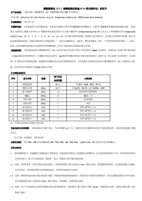
解脲脲原体(UU)核酸检测试剂盒(PCR-荧光探针法)说明书【产品名称】通用名称:解脲脲原体(UU)核酸检测试剂盒(PCR-荧光探针法)英文名称:Detection Kit for Nucleic Acid of Ureaplasma urealyticum (PCR-fluorescence probing)【包装规格】 32人份/盒【预期用途】本试剂盒用于定性检测尿道、生殖道分泌物拭子样本中的解脲脲原体核酸成分,主要用于解脲脲原体感染的临床辅助诊断。
根据相关文献研究,解脲支原体有14 株脲原体标准血清型可分为微小脲原体(Ureaplasma parvum,UP)1、3、6、14 和解脲脲原体(Ureaplasma urealyticum,UU)2、4、5、7、8、9、10、11、12、13,其中UP为条件致病菌,致病性与其含量有关,且普通人也有携带少量UP。
UU是引起非淋球菌性尿道炎、阴道炎等病症的主要致病菌之一,也是引起输卵管炎、盆腔炎、慢性前列腺炎、流产、产后热等的重要病原菌之一。
目前,临床上常用的脲原体检测方法有液体培养和核酸检测,但其并不能鉴别出其病菌是UP还是UU。
【检验原理】本试剂盒选用针对解脲脲原体(UU)特异性基因片段设计特异引物及特异Taqman荧光探针,该探针能与引物扩增区域中间的一段DNA摸板发生特异性结合,在PCR延伸反应过程中,Taq酶的外切酶活性将5´端荧光基团从探针上切割下来,使之游离于反应体系中,从而脱离了3´端荧光淬灭基团的屏蔽,即能接受光刺激而发出可供仪器检测的荧光,从而实现在全封闭反应体系中对解脲脲原体(UU)核酸的自动检测,发出荧光信号的强度与UU-DNA的量呈正相关。
【主要组成成份】注:不同批号试剂盒中各组份不能互换。
【储存条件及有效期】试剂应储存在-20℃保存,产品有效期为12个月,未使用完的试剂继续冷冻保存不影响其稳定性,但试剂反复冻融不得超过3次。
0I-F简明调试手册

编
第二轴 码 (K17)
器 编
第一轴 码 (K17)
器
JF3(N)
JF2(M)
(K27)
JF1(L)
制动器控制
(Z轴有抱闸的情况下需连接)
MCC
交流220V 交流220V
24V模块
DC 24V
交流220V 交流220V 交流220V
控
控
制
制
接触器
交流220V 交流220V 交流220V
电抗器
交流220V输 出
2
1. 0i-F 常见机型整体硬件连接
1.1 FS 0i-F αi-B 放大器+串行主轴
3
1.2 FS 0i-F βiSVSP-B 一体型放大器+串行主轴
0i MF/TF 综合接线图(βi -B一体型放大器+串行主轴)
BEIJING-FANUC
(K1) DC24V
CP1 CP2
FANUC 标准机床操作面板
2. 电缆明细 ................................................................................................................................................ 8 3. 通电前的检测项目 .............................................................................................................................. 21
第一轴电机编码器 第二轴电机编码器 第三轴电机编码器 主轴电机励磁状监控
UU简明使用手册

UUDynamics公司i STAR™产品客户端用户简明手册目的:通过SSL VPN产品安全的访问江西联通内部信息资源。
客户端访问设置步骤如下:步骤1:打开IE ,输入所需访问的地址。
自2010年4月21日零时起,市分电信宽带接入的营业厅通过https://218.64.57。
96访问vpn平台接入BSS系统,使用方法不变,原地址将不能访问。
利用联通宽带接入营业厅仍通过访问https://118。
212.189.2 访问vpn平台接入BSS系统。
步骤2:出现下面图1时候,请点击"是(Y)”.图1出现图2,显示下载ActiveX控件图2。
步骤3:当出现图3显示信息,为正常现象。
(XP等操作系统将所需要安装的插件屏蔽)步骤4:按照图4所示,点击安装ActiveX控件.图4.步骤5:出现图5信息,此为安装ActiveX控件提示信息,按照要求点击”安装(I)”,。
图5。
步骤6:ActiveX控件完毕,出现图6.1)使用USB KEY登录的用户,选择“UU 证书用户"的安全域,然后请查看步骤7图6。
步骤7 :点击图6中更多按钮,根据图7中的显示,点击安装,进行UUKey驱动的安装. (注意驱动安装过程中,请不要插入USB KEY)图7.步骤8:a:安装好UUKey驱动后,插上UUKey 。
b:选择您所需要登录的安全域(如图8.1所示),选择使用的证书(图8中为用户).图8.1.c:按照图8.2中显示点击高级,选择自动登录和自动登出,点击确定。
(以后插入UUKey,将实现自动登录,拔掉UUKey,将实现自动登出)。
图8。
2.步骤9:点击确定按钮,此时出现图9,要求输入USB KEY的PIN码(默认为111111),输入PIN码后,才可以访问内部应用程序。
如需更改PIN码,请看本文档末尾的注意事项二。
.图9输入完毕后,方可访问内部应用程序访问结束后,只需将USB Key拔出,就可以自动登出.客户端访问应用程序步骤如下:正确输入密码后,将可访问应用程序,如图A所示:图A一.访问Oracle系统程序步骤一右击Oracle系统图标,跳出菜单,选择“配置"如下图所示:跳出如下图所示的配置对话框,步骤二选择“浏览”,找到Oracle客户端软件的.exe文件,按“确定" 步骤三双击运行Oracle图表二访问“综合营帐系统"步骤1:双击运行工作台上的“综合营帐系统”图标,出现访问如下页面使用注意事项:1:所有应用程序运行后,第一个打开的主窗口都不能关闭.此窗口如下2:使用USB KEY访问的用户,可自己修改USB KEY的PIN码。
- 1、下载文档前请自行甄别文档内容的完整性,平台不提供额外的编辑、内容补充、找答案等附加服务。
- 2、"仅部分预览"的文档,不可在线预览部分如存在完整性等问题,可反馈申请退款(可完整预览的文档不适用该条件!)。
- 3、如文档侵犯您的权益,请联系客服反馈,我们会尽快为您处理(人工客服工作时间:9:00-18:30)。
UUDynamics公司iSTAR ?产品客户端用户简明手册
目的:通过SSL VPN产品安全的访问江西联通内部信息资源。
客户端访问设置步骤如下:
步骤1:
打开IE,输入所需访问的地址。
自2010年4月21日零时起,市分电信宽带接入的营业厅通过
https://218.64.57.96访问vpn平台接入BSS系统,使用方法不变,原地址将不能访问。
利用联通宽带接入营业厅仍通过访问https://118.212.189.2访问vpn平台接入BSS系统。
步骤2:
出现下面图1时候,请点击”是(丫)
图1
出现图2,显示下载ActiveX控件
图2
步骤3:
当出现图3显示信息,为正常现象°XP等操作系统将所需要安装的插件屏蔽)
,上― 聲再售下利h tfc*:畢自'亠"LEfk Tfcr "的L TT J U. r^h Exr-r.Ei ur. (.筆fB皑l1?!云1童离UUDEb 口一律化灾塞尊逮弊公霍咅
T豪U *'■/!Tm <iF汕迫liI 疋室邮由1・&晞
ic f er j TTw^urMWr^rtiT r ■干•予订师■督 *尹閒讦刃h
苦in. "tti迂眉的吃■,石疋!*下BE g® fli^. 三||中曲I3I・”工«—>51>5曲"1・「■■山狂,,5Edf 虫戛*览円凤壬_二皿・” 5'-H-正銓・卸中M 电■鼻■寻曙■昌1i世■?斜;
區i I■芳!<■;■〒竄Mr呵- ”冷
«dt SlULTfi—狎■Mfl=UUO”dmHlr4z££「■皐严下鼻下期事酗‘心第哉初、爭仝晋• il«£空歩珂詡皆矗理«:<-
"■幅師T屮
5 <| Tbranoi
步骤4:按照图4所示,点击安装ActiveX控件图4.
UUD/nanriQ ' -休比畫全善站办蓟萨台"EM
千.LLCSzma」乩]nc更啊心“般愛
K-fUlffif3 u 上审■岀音砂番邓円1卜irt * 1 Eitsi^ 1T«IT r*.
xtl- LldiefiPilEl^^LFT®!; JkJ&r:皇iE:晌團ii!ft 豊-Jl JI ->EntifinEtErt "・臣“H* Eli■兰吕盂亠□七1^ 步炮U 在袖■•山“
”住“r■:呻片■£*”關■*西“卩•畠耳r-円*•于■』虐“蜀-幅峠、
M下雹一『阳11电-日■也自丄伽2恥占•阳•】“宴£ •豪更丁下ITT辭砂止也瞰强昭0W - I res StfRtaflSfli ^te«3S •«.
WSiMfi TAPT
J m# _2
步骤5:
出现图5信息,此为安装ActiveX控件提示信息,按照要求点击”安装(I)”,。
图5.
UU&zn^ffme^
叵:Eff-OJG 栩
■ij 5
Pmnlo^dng. phw w*it・.
I ** I"«R屯黑则啊•耳i TAI ■p.simil wit頁匸TRiQ FXL
1___ J *l?l 池■仲■,八啊丄iLkr
f 1|?岀
JE―右址摘*TF"・ HZ 工白H»辱乂- *3 ™wv.Mib?i . rrw 卯母百e 帀打卅E&nm « *ttei址W
―佯优主辛藝繭卉金¥-占
步骤6:
ActiveX控件完毕,出现图6。
1)使用USB KEY登录的用户,选择“ UU证书用户”的安全域,然后请查看步骤7
图6.
步骤7 :
点击图6中更多按钮,根据图7中的显示,点击安装,进行UUKey驱动的安装。
(注意驱动安装过程中,请不要插入USB KEY)
图7.
步骤8:
a:安装好UUKey驱动后,插上UUKey。
b:选择您所需要登录的安全域(如图8.1所示),选择使用的证书(图8中为用户)。
图8.1.
用户认註偿J&
c:按照图8.2中显示点击高级,选择自动登录和自动登出,点击确定。
(以后插入UUKey,将实现自动登录,拔掉UUKey,将实现自动登出)
图8.2.
步骤9:点击确定按钮,此时出现图9,要求输入USB KEY的PIN码(默认为111111),输入PIN码后,才可以访问内部应用程序。
如需更改PIN码,请看本文档末尾的注意事项二。
.图9
甜+沏阖苞晞| 字帶)
放弃]
输入完毕后,方可访问内部应用程序
访问结束后,只需将USB Key 拔出,就可以自动登出
客户端访问应用程序步骤如下:
访问Oracle
系统程序
正确输入密码后,将可访问应用程序,如图 A 所示:
一芮甘十誓和升处T-[S
步骤一右击Oracle系统图标,跳出菜单,选择“配置” 如下图所示:
跳出如下图所示的配置对话框,
步骤二选择“浏览”,找到Oracle客户端软件的.exe文件,按“确定”
步骤三双击运行Oracle图表
二访问“综合营帐系统” 步骤1:双击运行工作台上的“综合营帐系统”图标,出现访问如下页面
f:e.isrts.FW,正云n否反E
dift 1J
使用注意事项:
1:所有应用程序运行后,第一个打开的主窗口都不能关闭。
此窗口如下
2:使用USB KEY访问的用户,可自己修改USB KEY的PIN码。
在Windows 右下角有个驱动在运行。
如图所示,
双击右下角图标后,如下图所示:
选择“修改用户密码”,出现如下对话框:
3:所有安装3721或者其他屏蔽工具的用户,请打开下载ACTIVX功能以及允许弹出式窗口。