美能达x700维修手册 第三部分
美能达复印机故障代码及维修模式中英文对照
美能达复印机故障代码及维修模式中英文对照美能达故障代码故障名称检测时机柯美数码复印机维修代码、维修模式C0000 主马达故障• 主马达开始运转1秒钟后的任何时候,主马达(M1)锁定信号会连续维持1 秒钟的高电平(HIGH)。
C0044ADF 冷却风扇故障(仅在安装选购件AFR-19 时)• 具体内容请参考选购件维修手册(AFR-19)。
C0045 定影冷却风扇马达故障• 在定影冷却风扇马达全速或减速运转期间,定影冷却风扇马达(M3) 锁定信号会连续维持1 秒钟的高电平(HIGH)。
C004E 电源冷却风扇马达故障• 在电源冷却风扇马达的远程信号维持在ON(表示全速动转)或OFF (表示减速动转)期间,电源冷却风扇马达(M4) 的锁定信号会连续维持1 秒钟的高电平(HIGH)。
C0070 主加粉马达故障• 在碳粉瓶正在转动期间,碳粉瓶原位感应器(PC7) 会连续3.5 秒钟输出高电平(HIGH) 信号。
• 在碳粉瓶正在转动期间,碳粉瓶原位感应器(PC7) 会连续2 秒钟输出低电平(LOW) 信号。
C0210 图像转印电压异常• 在PC 感光鼓保持静止状态时,图像转印电压在规定时间连续维持在100 V 以上。
C03FF 模式设置不当• 对维修模式中“调整”的“模式设置”设置不正确。
C0500 预热故障• 预热循环期间,在规定的时间过后,定影辊的表面温度仍未达到规定的水平。
从室温到100C: 35 秒从100C 到140C: 25 秒从140C 到完成预热循环:20 秒C0500预热故障(对于具有两个定影辊加热灯的型号)* 仅限于Di2011 • 预热循环开始后30 秒内,定影辊热敏电阻未检测到预定的温度,因而未完成预热循环。
• 预热循环期间,在规定的时间过后,定影辊的表面温度仍未达到规定的水平。
从室温到6OC: 4 秒从6OC 到10OC: 2 秒从10OC 到13OC: 1 秒从13OC 到155C: 0.5 秒C0501预热故障2 (对于具有两个定影辊加热灯的型号)* 仅限于Di2011• 预热循环开始后30 秒内,定影辊副热敏电阻未检测到预定的温度,因而未完成预热循环。
美能达Di152_183Main维修手册概述

FrameMaker Ver5.5E(PC) Di152/Di18301.06.19索引(概述)概述机械/电气FrameMaker Ver5.5E(PC) Di152/Di183 GENERAL01.08.27概述14413FrameMaker Ver5.5E(PC) Di152/Di183 GENERAL01.08.31目录1.技术规格...........................................................................................................G-12.安装注意事项....................................................................................................G-52-1.安装场所...................................................................................................G-5 2-2.电源...........................................................................................................G-5 2-3.接地...........................................................................................................G-53.使用注意事项....................................................................................................G-63-1.确保在最适当的条件下使用主机...............................................................G-6 3-2.操作环境...................................................................................................G-6 3-3.电源规格要求............................................................................................G-6 3-4.注意...........................................................................................................G-64.耗材的操作处理.................................................................................................G-75.其他注意事项....................................................................................................G-86.系统选购件........................................................................................................G-9iFrameMaker Ver5.5E(PC) Di152/Di183 GENERAL 01.08.27G-11.技术规格复印介质连续复印速度(张/分钟)类型原稿扫描系统光电导元件复印系统分辨率送纸系统曝光系统显影系统充电系统图像转印系统纸张分离系统定影系统纸张放电系统原稿最大尺寸::::::::::::::落地式/台式CCD 行感应器有机光电导元件静电干粉图像被通过激光被转印到普通纸上600× 600dpi2路系统手送进纸......单张纸盒......250张反射镜扫描MT-HG 系统带Scorotron 系统的梳状电极(1)DC 负电晕。
美能达技术维修模式精修订

美能达技术维修模式 SANY标准化小组 #QS8QHH-HHGX8Q8-GNHHJ8-HHMHGN#4.技术维修模式技术维修模式用来检查、设定、调整或注册各种维修功能。
4.1维修模式功能树_安装选购件时显示。
ServiceMode(维修模式)一、SERVICE'SCHOICE(技术维修选择)1、SHIPMENTDESTINATION(市场地区)2、MAINTENANCECOUNTER(保养计数器)3、IULIFESTOPMODE(IU寿命终止模式)4、IDADJUST(ID调整)5、VGADJUST(VG调整)6、FUSERTEMP.Ad(PLAIN)(定影温度调整(普通纸))7、FUSERTEMP.Ad(THICK)(定影温度调整(厚纸))8、FUSERTEMP.Ad(OHP)(定影温度调整(OHP))9、LEADINGEDGEERAGE(前边缘消除)10、TRAILINGEDGEERAGE(后边缘消除)11、VERTICALEDGEERAGE(上下边缘消除)12、LOOPADJUST(TRAY1)(波幅调整(第1纸盒))13、LOOPADJUST(TRAY2TOTRAY5)*(波幅调整(第2纸盒到第5纸盒)*)14、LOOPADJUST(DUPLEX)(波幅调整(双面))15、LOOPADJUST(BYPASS)(波幅调整(手送进纸))16、FLSPAPERSIZE(FLS纸张尺寸)17、CCDAPSSIZE(CCDAPS尺寸)18、GDITIMEOUT(GDI超时)二、ADJUST(调整)1、PRNMAINREGIST(打印主对位)2、PRNSUBREGIST(打印次对位)3、CCDMAINZOOM(CCD主缩放)4、CCDSUBZOOM(CCD次缩放)5、CCDMAINREGIST(CCD主对位)6、CCDSUBREGIST(CCD次对位)7、ADFSUBZOOM(ADF次缩放)8、ADFMAINREGIST(ADF主对位)9、ADFSUBREGIST1(ADF次对位1)10、ADFSUBREGIST2(ADF次对位2)11、ADFREG.LOOP1(ADF对位波幅1)12、ADFREG.LOOP2(ADF对位波幅2)13、ATDCGAIN(ATDC增益)14、MODELSETTING(模式设定)三、COUNTER(计数器)1、TOTALCOUNTER(总计数器)2、SIZECOUNTER(尺寸计数器)3、PMCOUNTER(PM计数器)4、MAINTENANCECOUNTER(保养计数器)5、SUPPLIESLIFECOUNT.(使用寿命计数)6、APPLICATIONCOUNTER(应用计数器)7、SCANCOUNTER(扫描计数器)8、PAPERSIZECOUNTER(纸张尺寸计数器)9、MISFEEDCOUNTER(卡纸计数器)10、TROUBLECOUNTER(故障计数器)四、DISPLAY(显示)1、TONERDENSITYLEVEL(碳粉浓度水平)2、PROCESSCONTROL(过程控制)3、MAINF/WVER.(主机固件版本)4、ENGINEF/WVER.(引擎固件版本)5、PCLF/WVER.*(PCL固件版本*)6、NICF/WVER.*(网卡固件版本*)7、ADFF/WVER.*(ADF固件版本*)8、MAINRAMSIZE(主内存大小)9、PCLRAMSIZE*(PCL内存大小*)10、SERIALNO.(序列号)11、CUSTOMERID(用户识别码)五、FUNCTION(功能)1、PAPERFEEDTEST(送纸测试)2、PROCESSCHECK(过程检查)3、ATDCAUTOADJUST(ATDC自动调整)4、PRINTTESTPATTERN(打印测试图案)5、ADFFEEDTEST(ADF输稿测试)6、COPYADFGLASSAREA(复印ADF玻璃区域)7、CCDMOVETOHOME(CCD移到原位)8、SCANTEST(扫描测试)9、ADFWIDTHADJ.(MAX)*(ADF宽度调整(最大)*)10、ADFWIDTHADJ.(MIN)*(ADF宽度调整(最小)*)11、ADFSENSORADJUST*(ADF感应器调整*)六、ADMIN.REGISTRATION(管理员注册)七、FIXEDZOOMCHANGE(固定缩放修改)1、REDUCTION2(缩小2)2、REDUCTION1(缩小1)3、EXPANSION1(放大1)4、EXPANSION2(放大2)七、FIXEDZOOMCHANGE(固定缩放修改)八、FACTORYTEST(出厂测试)1、PANELBUZZERTEST(面板蜂鸣器测试)2、RAMTEST(RAM测试)九、CLEARDATA(清除数据)1、MEMORYCLEAR(清除内存数据)2、PMCOUNTER(PM计数器)3、MAINTENANCECOUNTER(保养计数器)4、SUPPLIESLIFECOUNT.(使用寿命计数)5、APPLICATIONCOUNTER(应用计数器)6、SCANCOUNTER(扫描计数器)7、PAPERSIZECOUNTER(纸张尺寸计数器)8、MISFEEDCOUNTER(卡纸计数器)9、TROUBLECOUNTER(故障计数器)10、ADFBACKUPCLEAR*(ADF备份数据清除*)十、SECURITY(安全性)1、TOTALCOUNTERCOUNT(总计数器计数)2、SIZECOUNTERCOUNT(尺寸计数器计数)3、PLUG-INCOUNTERCOPY(接插式计数器复印)4、MACHINECOUNTER(机器计数器)注意必须注意只有专业维修人员才能进入维修模式。
技巧关于美能达X700手动系统
不容错过的135手动系统——美能达X700随着AF的应用,相信坛子里的烧友很少用手动的MinoltaX-700了,渐渐地卷入了NCMP的大战。
在这里我想把无忌泡菜曾经谈过的X-700的话题综合起来,便于大家交流,不为别的,就因为他的性价比非常适合于工薪及学生使用,但它决不是一款低档机。
而且它的功能并不见得少,质量也可靠。
有说错之处,请指正。
如果你是一个非常喜欢手动聚焦,并想全程控制曝光的低收入爱好者,我建议你用X-700。
或者你是一个低收入的严肃摄影爱好者,建议你用X-700。
因为X-700能满足你的要求。
首先,价格在1700~1850元间的低价位一般都能接受,当年该机与NikonFM2一同进入中国时,其价格大约1500元左右,还曾有一段时间价格超过FM2。
毕竟它不是金属机身,也不是纵走钛合金快门,也没有0秒的闪光同步,落到今天的地步。
但它的确是一款名机,曾有许多名家认为它是一款够得上专业的专业机。
X-700的黑色外观棱角分明,有一种坚固感,美中不足是它的外壳是非金属的,让人有几分不放心。
它的体积也不大,重量只有505克,右边的小把手小巧不滑,单手握持舒适稳当。
该机的主要功能有手动曝光(MF)、光圈先决(A)、程序自动(P)、TTL闪光、B门等。
(一)手动曝光使用该挡可全程控制光圈、快门,但它的最快速度只有00秒,与现在的相机比显得不够快,甚至还赶不上凤凰303的00秒。
实际上,在平时1/1000、00秒的快门都很少遇到。
一来,X-700的用家用28-70/3.5-4.5或70-210/4.5-5.6的变焦较多,即使使用f/1.4-f/2的大光圈的镜头,00秒的速度也勉强够用。
二来,普通用家一般选择的胶卷为10,00秒也能对付。
个人认为,本着够用的原则,不必去追求平时很少用的功能。
另外,如果你有独立的测光表,想按照独立测光表的曝光值曝光,就得用MF。
使用大型闪光灯、或M级、MF级、EP级闪光灯泡时也得用MF。
Uniden DCX 700 说明书

UU869BH_TCX700 OM.fm Page 2 Wednesday, June 2, 2004 10:46 AM WelcomeCongratulations on your purchase of the Uniden DCX700 optional handset and charger. This expansion handset is for use with the Digital Spread Spectrum series: DCT746, DCT748, and DCT7488 (model numbers may vary). Each model within this series will support up to four handsets. You can place a fully featured cordless handset anywhere in your home as long as you have AC power is available to connect the handset charging cradle. IMPORTANTThe DCX700 expansion handset will not operate unless it has been registered to your main base. This manual describes how to set up and connect your new handset; for instructions on operating your new handset, refer to the owner's manual supplied with your main base.To purchase expansion handsets (DCX700), visit our web site at .Backward / Forward CompatibilityYour phone may be compatible with other Uniden 2.4 GHz Digital**************************************************.com<>.Checking the Package ContentsMake sure you have received the following items in the package.If any of these items are missing or damaged, contact the Uniden Parts Department.•Cordless Handset•Charging Cradle•Battery Pack (BT-446)(Capacity: 800 mAH, 3.6V)•AC Adapter (AD-0005)(INPUT: 120V AC 60Hz) (OUTPUT: 9V DC 210 mA)•Beltclip•This Owner’s Manual•Other Printed MaterialUniden Parts Department at (800) 554-3988Hours: M-F 8:00 a.m. to 5:00 p.m. CST.or visit our website at– 2 –– 3 –Installing Your Expansion HandsetFollow these three easy steps before using your new cordless handset.1Install the battery pack.2Connect the charger and charge your new handset for 15-20 hours.3Register your new handset to the main base.Step 1: Install the Battery Pack 1Press down on the handset battery case cover (use the finger indention for a better grip) and slide the cover downward to remove.2Plug the battery pack connector (red & black wires) into the jack inside the battery compartment. (The connector notches fit into the grooves of the jack only one-way.) Match the wire colors to the polarity label in the battery compartment, and push the connector in until you hear a click.3Make sure you have a good connection by slightly pulling on the battery wires. If the connection is secure, the battery jack will remain in place.4Place the battery case cover back on the handset by sliding it upwards until it clicks into place.5Place the handset in the charging cradle with the keypad facing forward.Use only the Uniden battery (BT-446) supplied with your phone. Replacement batteries are also available through the Uniden Parts Department. (See page 2.)•Recharge your handset on a regular basis by returning the handset to the charger after each phone call.Rechargeable Nickel-Metal-Hydride BatteriesMust Be Recycled or Disposed of ProperlyUU869BH_TCX700 OM.fm Page 3 Wednesday, June 2, 2004 10:46 AM– 4 –Step 2: Connect the Charger 1Connect the AC adapter to the DC IN 9V jack and to a standard 120V AC wall outlet.2Set the charger on a desk or tabletop, and place the handset in the charger with the keypad facing forward.3Make sure the charge LED illuminates. If the LED does not illuminate, check good contact with the charger charging e only the supplied AD-0005 AC adapter. Do not use any other AC adapter.Place the charger close to the AC outlet so that you can unplug the AC adapter easily.4Charge the handset for 15-20 hours before using.Step 3: Register the HandsetYOU NEED TO REGISTER THE DCX700 TO THE MAIN BASE BEFORE USE!1Be sure the handset battery is fully charged.2 For DCT746 and DCT748 models (model numbers may vary)With the main base in standby mode (i.e., not being used), place the extra handset in the main base to begin registration.For DCT7488 (corded base model)1) With the main base in standby mode, press the MENU soft key on 2) Press or on the base to selectHS , and then press the OK soft key.3) Base LCD screen will display the following prompt:-On handset press & hold "#" key for 2 sec 4) On the handset, press and hold # for 2 seconds. To cancel registration, press the CANCEL soft key on the base.For compatible models (DCT6 series) (model number may vary)1)Disconnect the AC adapter.2)While holding find handset (or intercom for DCT6485 models), connect the AC adapter. Keep pressing the key until the CHARGE LED starts to blink.3)On the handset, press and hold # until you hear beep.3While the handset is registering, Handset Registering will appear in the handset LCD. When Registration Complete is displayed, the handset has been registered to the base.If Registration Failed appears, please try these steps again.UU869BH_TCX700 OM.fm Page 4 Friday, June 4, 2004 5:22 PM– 5 –Using Your Expansion HandsetNow that your new handset is registered, it can perform all the same functions as the handsets originally included with your phone. With your new handset, you can •Transfer calls or intercom between handsets and base (depending on model)•Use two handsets as 2-way radios in DirectLink mode •Use two handsets as a baby/room monitor •Hold 3 or 4-way conference calls (depending on model) •Access your main base's integrated answering device (if available)•Access voice mail using handsets or main base (depending on model)See the owner's manual that came with your main base for complete instructions on operating your new expanded digital phone.Battery InformationLow battery alertWhen the batteries are very low and need to be charged, the phone is programmed to eliminate functions in order to save power.The batteries need to be charged when:- The empty battery icon appears.- Low Battery appears in the display.If the phone is in standby mode, none of the keys will operate.If you are on a call, complete your conversation as quickly as possible, and return the handset to the charging cradle.Cleaning the battery charging contacts To maintain a good charge, it is important to clean the charging contacts on the handset once a month. Using water only, dampen a cloth to clean the charging contacts. Then make returning the handset to the charger to charge.Caution: Do not use paint thinner, benzene, alcohol, or other chemical products. Doing so may discolor the surface of the telephone and damage the finish.UU869BH_TCX700 OM.fm Page 5 Wednesday, June 2, 2004 10:46 AM– 6 –I.C. NoticeTERMINAL EQUIPMENTNOTICE: This equipment meets the applicable Industry Canada Terminal Equipment TechnicalSpecifications. This is confirmed by the registration number. The abbreviation, IC, before theregistration number signifies that registration was performed based on a Declaration ofConformity indicating that Industry Canada technical specifications were met. It does notimply that Industry Canada approved the equipment.NOTICE: The Ringer Equivalence Number (REN) for this terminal equipment is marked on theequipment itself. The REN assigned to each terminal equipment provides an indication of themaximum number of terminals allowed to be connected to a telephone interface. Thetermination on an interface may consist of any combination of devices subject only to therequirement that the sum of the Ringer Equivalence Numbers of all the devices does not exceedfive.RADIO EQUIPMENTThe term “IC:” before the radio certification number only signifies that Industry Canadatechnical specifications were met.Operation is subject to the following two conditions: (1) this device may not causeinterference, and (2) this device must accept any interference, including interference that maycause undesired operation of the device. “Privacy of communications may not be ensured whenusing this telephone.”As an Energy Star Partner, Uniden has determined that this product or productmodels meets the Energy Star guidelines for energy efficiency.Energy Star is a U.S. registered mark.THE FCC WANTS YOU TO KNOWChanges or modifications to this product not expressly approved by Uniden, or operation ofthis product in any way other than as detailed by the owner's manual, could void yourauthority to operate this product.This device complies with part 15 of the FCC rules. Operation is subject to the following twoconditions: (1) This device may not cause harmful interference, and (2) This device mustaccept any interference received, including interference that may cause undesired operation.Privacy of communications, may not be ensured when using this phone.To insure the safety of users, the FCC has established criteria for the amount of radio frequencyenergy various products may produce depending on their intended usage. This product hasbeen tested and found to comply with the FCC's exposure criteria. For body worn operation, theFCC RF exposure guidelines were also met when used with the Uniden accessories supplied ordesigned for this product. Use of other accessories may not ensure compliance with FCC RFexposure guidelines and should be avoided.Uniden works to reduce lead content in our PVC coated cords in our products and accessories.Warning!The cords on this product and/or accessories contain lead, a chemical known to the State ofCalifornia to cause birth defects or other reproductive harm. Wash hands after handling .UU869BH_TCX700 OM.fm Page 6 Wednesday, June 2, 2004 10:46 AMUU869BH_TCX700 OM.fm Page 7 Wednesday, June 2, 2004 10:46 AMOne Year Limited WarrantyImportant: Evidence of original purchase is required for warranty service.WARRANTOR: UNIDEN AMERICA CORPORATION (“Uniden”)ELEMENTS OF WARRANTY: Uniden warrants, for one year, to the original retail owner, this Uniden Product to be free from defects in materials and craftsmanship with only the limitations or exclusions set out below. WARRANTY DURATION: This warranty to the original user shall terminate and be of no further effect 12 months after the date of original retail sale. The warranty is invalid if the Product is (A) damaged or not maintained as reasonable or necessary, (B) modified, altered, or used as part of any conversion kits, subassemblies, or any configurations not sold by Uniden, (C) improperly installed, (D) serviced or repaired by someone other than an authorized Uniden service center for a defect or malfunction covered by this warranty, (E) used in any conjunction with equipment or parts or as part of any system not manufactured by Uniden, or (F) installed or programmed by anyone other than as detailed by the owner’s manual for this product.STATEMENT OF REMEDY: In the event that the product does not conform to this warranty at any time while this warranty is in effect, warrantor will either repair or replace the defective unit and return it to you without charge for parts, service, or any other cost (except shipping and handling) incurred by warrantor or its representatives in connection with the performance of this warranty. Warrantor may replace the unit with a new or refurbished unit. THE LIMITED WARRANTY SET FORTH ABOVE IS THE SOLE AND ENTIRE WARRANTY PERTAINING TO THE PRODUCT AND IS IN LIEU OF AND EXCLUDES ALL OTHER WARRANTIES OF ANY NATURE WHATSOEVER, WHETHER EXPRESSED, IMPLIED OR ARISING BY OPERATION OF LAW, INCLUDING, BUT NOT LIMITED TO ANY IMPLIED WARRANTIES OF MERCHANTABILITY OR FITNESS FOR A PARTICULAR PURPOSE. THIS WARRANTY DOES NOT COVER OR PROVIDE FOR THE REIMBURSEMENT OR PAYMENT OF INCIDENTAL OR CONSEQUENTIAL DAMAGES. Some states do not allow this exclusion or limitation of incidental or consequential damages so the above limitation or exclusion may not apply to you.LEGAL REMEDIES: This warranty gives you specific legal rights, and you may also haveother rights which vary from state to state. This warranty is void outside the United States of America and Canada.PROCEDURE FOR OBTAINING PERFORMANCE OF WARRANTY: If, after following the instructions in the owner’s manual you are certain that the Product is defective, pack the Product carefully (preferably in its original packaging). Disconnect the battery from the Product and separately secure the battery in its own separate packaging within the shipping carton. The Product should include all parts and accessories originally packaged with the Product. Include evidence of original purchase and a note describing the defect that has caused you to return it. The Product should be shipped freight prepaid, by traceable means, to warrantor at:Uniden America CorporationParts and Service Division4700 Amon Carter Blvd.Fort Worth, TX 76155(800) 297-1023, 8 a.m. to 5 p.m. Central, Monday through FridayMay be covered under one or more of the following U.S. patents:4,523,0584,595,7954,797,9165,381,4605,426,6905,434,905 5,491,7455,493,6055,533,0105,574,7275,581,5985,650,7905,660,269 5,661,7805,663,9815,671,2485,696,4715,717,3125,732,3555,754,407 5,758,2895,768,3455,787,3565,794,1525,801,4665,825,1615,864,619 5,893,0345,912,9685,915,2275,929,5985,930,7205,960,3585,987,330 6,044,2816,070,0826,125,2776,253,0886,314,2786,418,209– 7 –。
柯尼卡美能达bizhubC300C352维修手册现场维修道
柯尼卡美能达bizhub C300 C352维修手册现场维修道现场维修总目录安全和重要警告事项 ................................................................. ........................................S-1 重要注意事项 ................................................................. ..........................................................S-1 危险、警告和注意事项说明 ................................................................. ..................................S-1 安全警告 ................................................................. ..................................................................S-2 机器上的警告标识 ................................................................. ................................................S-18发生事故时的措施 ..................................................................... .....................................S-20维修手册的组成 ..................................................................... .......................................... C-1维修手册中使用的符号 ..................................................................... ...............................C-2bizhub C300/C352 主机概述 ................................................................. ........................................................................ ...... 1 维修保养 ................................................................. . (9)调整,设置 ................................................................. .............................................................. 181 故障排除 ................................................................. (409)附录 ................................................................. ........................................................................ .. 533标准控制器 ?攀?................................................................. ........................................................................ ...... 1 维修保养 ................................................................. . (3)调整,设置 ................................................................. ................................................................ 37 故障排除 ................................................................. .. (39)自动双面器单元 (AD-503) 概述 ................................................................. ........................................................................ ...... 1 维修保养 ................................................................. . (3)调整,设置 ................................................................. .................................................................. 7 故障排除 ................................................................. ....................................................................11DF-608 概述 ................................................................. ........................................................................ ...... 1 维修保养 ................................................................. . (5)调整,设置 ................................................................. ................................................................ 25 故障排除 ................................................................. ....................................................................49PC-103/PC-203 概述 ................................................................. ........................................................................ ...... 1 维修保养 ................................................................. . (3)调整,设置 ................................................................. ................................................................ 13 故障排除 ................................................................. .. (19)i PC-403 概述.................................................................. ........................................................................ ......1 维修保养.................................................................. . (3)调整,设置.................................................................. ................................................................17 故障排除.................................................................. .. (25)FS-514/PK-510/OT-601 概述.................................................................. ........................................................................ ......1 维修保养.................................................................. . (7)调整,设置.................................................................. ................................................................45 故障排除.................................................................. .. (59)MT-501 概述.................................................................. ........................................................................ ......1 维修保养.................................................................. . (3)调整,设置.................................................................. ..................................................................7 故障排除.................................................................. .. (13)SD-503 概述.................................................................. ........................................................................ ......1 维修保养.................................................................. . (3)调整,设置.................................................................. ................................................................25 故障排除.................................................................. .. (37ii)安全和重要警告事项安全和重要警告事项进行维修工作之前,请仔细阅读以下所述的安全和重要警告事项。
柯美系列维修模式大全

柯美系列维修模式大全进入维修模式1、按效用键;2、按照如下顺序按下列键;3、停止→ 0 → 0 → 停止→ 0 → 1;4、将出现维修模式菜单屏幕(Service Mode )。
退出维修模式按面板复原键多次,直到原来的屏幕重新出现为止。
修改维修模式功能设定值步骤1、用[ ▲/▼ ] 键选择所需的项目;2、用[▲/▼ ] 键、[ ] 键、或数字键盘选择设定值;3、确认选择,按[Yes] 键;4、返回前面的屏幕,按[No] 键。
柯尼卡美能达162/210技术维修模式(Service Mode )菜单编号英文项目中文项目内容1 SERVICE'S CHOICE 技术维修选择? SHIPMENT DESTINATION (市场地区)MAINTE NANCE COUNTER (保养计数器)IU LIFE STOP MODE (IU 寿命终止模式)ID ADJUST (ID 调整)VG ADJUST (VG 调整)FUSER TEMP. Ad (PLAIN) (定影温度调整(普通纸))FUSER TEMP. Ad (THICK) (定影温度调整(厚纸))FUSER TEMP. Ad (OHP) (定影温度调整(OHP) )LEADING EDGE ERAGE (前边缘消除)TR AILING EDGE ERAGE (后边缘消除)VERTICAL EDGE ERAGE (上下边缘消除)LOOP ADJUST (TRAY1) (波幅调整(第1 纸盒))LOOP ADJUST (TRAY2 TO TRAY5)* (波幅调整(第2 纸盒到第5 纸盒)* )? LOOP ADJUST (DUPLEX) (波幅调整(双面))LOOP ADJUST (BYPASS) (波幅调整(手送进纸))FLS PAPER SIZE (FLS 纸张尺寸)CCD APS SIZE (CCD APS 尺寸)GDI TIMEOUT (GDI 超时)2 ADJUST 调整? PRN MAIN REGIST (打印主对位)PRN SUB REGIST (打印次对位)CCD MAIN ZOOM (CCD 主缩放)CCD SUB ZOOM (CCD 次缩放)CCD MAIN REGIST (CCD 主对位)CCD SUB REGIST (CCD 次对位)ADF SUB ZOOM (ADF 次缩放)ADF MAIN REGIST (ADF 主对位)ADF SUB REGIST1 (ADF 次对位1 )ADF SUB REGIST2 (ADF 次对位2 )ADF REG. LOOP 1 (ADF 对位波幅1 )ADF REG. LOOP 2 (ADF 对位波幅2 )ATDC GAIN (ATDC 增益)MODEL SETTING (模式设定)3 COUNTER 计数器? TOTAL COUNTER (总计数器)SIZE COUNTER (尺寸计数器)PM COUNTER (PM 计数器)MAINTENANCE COUNTER (保养计数器)SUPPLIES LIFE COUNT. (使用寿命计数)APPLICATION COUNTER (应用计数器)SCAN COUNTER (扫描计数器)PAPER SIZE COUNTER (纸张尺寸计数器)MISFEED COUNTER (卡纸计数器)TROUBLE COUNTER (故障计数器)4 DISPLAY 显示? TONER DENSITY LEVEL (碳粉浓度水平)PROCESS CONTROL (过程控制)MAIN F/W VER. (主机固件版本)ENGINE F/W VER. (引擎固件版本)PCL F/W VER.* (PCL 固件版本* )NIC F/W VER.* (网卡固件版本* )ADF F/W VER.* (ADF 固件版本* )MAIN RAM SIZE (主内存大小)PCL R AM SIZE* (PCL 内存大小* )SERIAL NO. (序列号)CUSTOMER ID (用户识别码)5 FUNCTION 功能? PAPER FEED TEST (送纸测试)PROCESS CHECK (过程检查)ATDC AUTO ADJUST (ATDC 自动调整)PRINT TEST PATTERN (打印测试图案)ADF FEED TEST (ADF 输稿测试)COPY ADF GLASS AREA (复印ADF 玻璃区域)CCD MOVE TO HOME (CCD 移到原位)SCAN TEST (扫描测试)ADF WIDTH ADJ. (MAX) (ADF 宽度调整(最大)* )ADF WIDTH ADJ. (MIN) (ADF 宽度调整(最小)* )ADF SENSOR ADJUST (ADF 感应器调整* )6 软开关7 REPORT 报告? 维修数据列表、错误代码列表、T30协议列表9 FIXED ZOOM CHANGE 固定缩放修改? REDUCTION2 (缩小2 )、REDUCTION1 (缩小 1 )、EXPANSION1 (放大 1 、EXPANSION2 (放大2 )10 工厂测试? 信号测试、中继测试、拔号测试、音量测试11 CLEAR DATA 清除数据? MEMORY CLEAR (清除内存数据)PM COUNTER (PM 计数器)MAINTENANCE COUNTER (保养计数器)SUPPLIES LIFE COUNT. (使用寿命计数)APPLICATIO N COUNTER (应用计数器)SCAN COUNTER (扫描计数器)PAPER SIZE COUNTER (纸张尺寸计数器)MISFEED COUNTER (卡纸计数器)TROUBLE COUNTER (故障计数器)ADF BACKUP CLEAR* (ADF 备份数据清除* )物业安保培训方案为规范保安工作,使保安工作系统化/规范化,最终使保安具备满足工作需要的知识和技能,特制定本教学教材大纲。
美能达7516维修手册
步 操作
骤 1 初步检查 2 M1/AF操作检查 3 PC3/AF传感器检查
参考页
5-2 5-1
4 更换PWB/APWB/AF CN2/AF-6 (ON)
D-6 (AF-2000) H-4 (AF-2000)
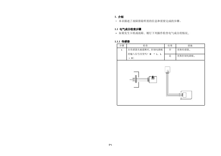
2.5.9 在原稿出稿部分的卡纸 安装了选项自动原稿输稿器AF-2000时 <检测时序>
类型
描述
取纸部分的
在取纸电磁铁(SL21/MB)触发后过了特定的时间间隔 纸张的前
卡纸检测 沿没有触发同步辊传感器(PC1)
尺寸错误的 检测
在纸张触发同步辊传感器(PC1)后过了特定的时间间隔 同步辊 传感器(PC1)未被遮断
同步辊传感器(PC1)在特定的时间间隔以前被遮断
<措施>
同步辊传感器(PC1) 取纸电磁铁(SL21/MB)
取纸/竖直送 纸传感器(PC12/PF)被遮断
纸部分
<措施>
同步辊传感器(PC1) 取纸电磁铁(SL11/PF)
有关电气成分 取纸传感器(PC12/PF) 主电路板(PWB-A)
步 操作
骤 1 初步检查 2 PC1传感器检查 3 SL11/PF操作检查
4 PC12/PF传感器检查
5 更换PWB-A
参考页
骤 1 初步检查 2 PC1传感器检查 3 SL2操作检查
4 PC2传感器检查 5 更换PWB-A
参考页
接线图
控制信号
位置(电气成分)
5-1
PWB-A PJ17A-3 (ON)
F-8
5-2
PWB-A
F-6
PJ12A-2 (REM)
5-1
PWB-A PJ12A-5 (ON)
CMI700产品说明书

C M I700系列产品说明书1.产品介绍1.1 仪器用途1.2 工作环境1.3 供电联接2.安装2.1.1 拆箱2.1.2 连线2.1.3 主要联接2.1.4 打印机(可选配)2.1.5 探头3.仪器构造3.1 前面板3.2 后面板3.3 键盘3.4 菜单构成3.4.1 跳过3.4.2 语言3.4.3 对比度3.4.4 打印机开/关3.4.5 关于屏幕3.4.6 安装菜单3.4.7 EMX/MRX/BMX模块菜单4.启动4.1 系统安装4.2 调校4.3 测量4.4 输入屏5.安装菜单5.1 时间设定5.2 用户控制屏5.3 打印机选项屏5.4 模式系列选项屏5.5 系统选项屏5.6 工厂选项屏5.7 调校和调整屏5.8 测试和选项屏6.E M X模块菜单6.1 操作原理6.2 EMX调校6.2.1 调校程序6.2.2 EMX调校明细屏6.2.3 EMX编辑/变更调校屏6.2.4 EMX重新调校7.M R X模块菜单7.1 操作原理7.2 MRX调校7.3 调校程序7.4 MRX调校明细7.5 MRX编辑/变更调校7.6 MRX重新调校7.7 快检板应用8.B M X模块菜单8.1 操作原理8.2 BMX调校8.2.1 调校程序8.2.2 BMX调校明细8.2.3 BMX编辑/变更调校8.2.4 BMX重新调校9.测量9.1 测量模式9.2 测量程序9.3 测量屏9.3.1 测量屏---单读9.3.2测量屏---复读9.3.3测量屏---趋势图9.3.4测量屏---X&R图9.3.5 柱状图10.打印10.1 打印控制屏10.2 票单打印样品10.3 题头打印样品11.规格11.1.1 一般规格11.1.2 涡流模式11.1.3 磁性模式11.1.4 镀镍模式11.2 MRX 模块11.2.1 TRP微型探头11.2.2 TRP标准探头11.3 BMX模块11.3.1 PM-147同位素11.3.2 TL-204同位素11.3.3 SR-90同位素12. 维护12.1 清洁12.2 电池1. 产品介绍1.1仪器用途CMI700系列是一款具有标准组件,无破坏性的涂/镀层厚度测量仪,其设计目的为精确测量不同基材上的不同涂/镀层厚度,CMI700系列产品可与以下三款测量模块联合配臵:MRX,BMX,EMX.EMX 模块可与任一磁性,涡流或镀镍测量原理配臵.1.2工作环境该仪器采用测量粗糙度微处理芯片设计,为实验室级精密仪器,能用于商店环境,使用时需要一个平整稳固的足够大的合适桌子,要求该桌子能完全摆放下仪器、待测品和在线制品。
美能达复印机维修手册

解决方案: 副 本白版问题 涉及到的部 品有:充电 架、转分电 极组件及高 压HV1。维 修时,先拆 下充电架、 转分电极组 件,查看是 否受潮。如 充电架或转 分电极座受 潮,就会导 致副本白版 现象。现场 检查发现由 于转分电极 座漏电造成 白版故障。 更换转分电 极座。
现象: 副本部 分发虚 原因: 间隙轮 磨损
解决方案: 对 于复印品质 量,一般先 检查感光鼓 上的影象是 否正常。如 鼓上影像正 常,应考虑 纸张是否受 潮、转分是 否漏电、转 分电极丝是 否脏。复印 量较大时, 检查间隙轮 是否磨损。 如发现间隙 轮磨损,更 换磁辊两端 的间隙轮, 故障解决。
现象: 副本部 分黑板 原因: 第三反 光镜移位
现象: 开机操 作面板无显 示 原因: 与主板 连接的RAM PACK损坏
解决方案: 对 于面板无显 示,可能引 起故障的部 品包括电源 (PU2)、 主板的IC和 RAM PACK 。先对机器 进行记忆清 除;如果不 能排除故 障,再检查 电源PU2对 面板是否有 5v输出、IC 与主板的连 接以及RAM PACK与主 板的连接。 经维修员检 查由于RAM PACK损坏 造成面板无 显示。更换 新RAM PACK,将 前门数据输 入后,机器 恢复正常
现象: 故障代 码C0070 原因: 碳粉瓶 原位检测传 感器PC112 失效。
解决方案: 发 生加粉故 障,维修人 员及用户不 能用力转动 粉瓶。如用 力转动会造 成传动机构 损坏。先复 印2~3张全 黑副本,查 看其是否转 动。如粉瓶 转动,检查 PC112原位 传感器与主 板的连接及 信号传递是 否可靠。开 始转动时, PWB-A上的 PJ22A-10的 电位是否由 0v变到5v。 如果正常, 检查主板, 再检查传感 器PC112。 如果粉瓶不 转动,应检 查传动机构 。更换检测 传感器 PC112
山东美能达健身器材股份有限公司产品手册说明书

山东美能达健身器材股份有限公司让未来现在就来Shandong Minolta Fitness Equipment Co.,LtdL e t F u t u r e C o m e N o w !美能达Product Brochure产品手册资质证书Certification1目录Catalogue关于我们About us Cardio Strength有氧产品力量产品公司简介Company Profile Cardio SeriesFS SeriesFM SeriesF SeriesPL SeriesC SeriesH SeriesG SeriesHA Series360 SeriesCardio Series Product有氧系列FS系列FM系列更多有氧产品F系列PL系列C系列H系列G系列HA系列360系列003005039035033FB SeriesFF SeriesFH SeriesAN SeriesFB系列FF系列FH系列AN系列049053043061071084111091094097107010203Accessor Series配件系列1182公司简介CorporateProfile15万平方米150000 square meters factory site11 seriesmore than 500+ models11大系列500+规格山东美能达健身器材股份有限公司是一家专业从事研发、 设计、 生产、 销售、 服务为一体的综合健身器材生产厂家, 成立于2010年, 坐落于山东宁津银河开发区, 拥有自主兴建的15万平方米的厂房, 包括大型车间, 全方位一流的展示厅和质量检测实验室等。
我公司拥有一批优秀的设计师 工程师, 外贸和专业管理人才, 通过不断的研发和引进国外先进技术, 完善和改进工艺流程, 严抓严品质量, 我们公司的产品具有设计合理、 样式新颖、 美观耐用、 不退色、 抗老化等特点。
MINOLTA DI470 DI552打印机 维修手册

7. 禁止湿手操作。 • 禁止使用湿手拔掉或者插上电源电缆,或者进行任何维修或检查工作。
P-2
警告
8. 禁止触摸ห้องสมุดไป่ตู้温部件。 • 在其左边标有该符号的零件,如曝光灯和定影辊等零件,在机器通电时会很 热。触摸它们可能造成灼伤。 • 要更换它们或者其周围的零件,必须等其冷却下来后才能进行。
P-3
注意
2. 卸下盖板和零件进行维修时的预防措施。 • 在任何可能的地方给该产品通电时,要装上所有的零件和盖板。 • 如果一定要在通电时卸除盖板,那就绝对不能碰任何带电零件,并要注意不要 让那些运动的部件夹住您的衣服,也不得让机器在无人照料的情况下处于该状 态。 • 禁止将卸下的零件或者装有液体的容器放置在机器上。如果零件掉入机器或者 液体流入机器,将造成电击或者火灾。 • 禁止在机器附近使用喷雾器,否则将导致火灾。 • 在卸下或者安装线路板,插上或者拔下插头之前,确保先拔掉电源线。 • 在打开或卸下盖板时,务必使用门开关夹具打开门开关。使用折叠的纸张或其 它物品将损坏门开关机构,并可能造成电击,损坏或失明。
• 在进行检查和维修时,为防止意外事故并保证最大安全,请遵守以下的预防措施。 @ 下面给出的一些预防措施不适用于某些型号。 • 具有特定含义的不同符号具体意义如下:
警告
• 指示潜在地危险情形,如不避免,将造成死亡或者严重伤害。
注意
• 指示潜在地危险情形,如不避免,有可能造成轻微或者中度伤害,还可以用作危险做法 的警报。
电的导电垫上。 • 禁止用手直接触摸集成电路的引脚。 • 保护 PWB 线路板不受外力作用以免弯曲或者破损。
柯尼卡美能达MFMF基本设置和常见故障解决PPT学习教案

会出现以下四种选项,使用▲、▼选择需要的选项。
按0K键确认。
按红色“停止”键退出当前画面。
选项:
1. 开:当发送任务正常执行后,或者是发送任务最
终没有完成,打印一份报告。
2. 关闭:不需要发送报告。
3. 始终:每次发送都打印一个报告。
4. 出错时:在发送失败,并最终发送请求被放弃,
打印报告。
第6页/共21页
3. 传真-应答.:本机会自动接收传真信息,电话机则会自动接收
电话.(需发送方先给接收方传真信号,接收方才会开始接收传真,
否则接收方不会接收传真,常用在有外接留言设备的传机器上)
第5页/共21页
关闭发送报告
快捷操作步骤:▼231-设置/发送/发送报告
具体操作方法:
按下▼,用键盘输入2、3、1。
头时,则选择为关闭,此时必须保证国家代码设备为 China。) 按0K键确认。 按红色“停止”键退出当前画面。
第11页/共21页
设置传真的发送传真头1\2
需要执行两个步骤来完成设置: 打开传真头功能。 设置发送方的名称和电话号码。
操作1. 快捷操作步骤:▼292-设置/技术参数/发送报头
具体操作方法: 按下▼,用键盘输入2、9、2,按OK键确认。 按▲ / ▼按钮,选择到开。(当客户想关闭发送传真
头时,则选择为关闭,此时必须保证国家代码设置为 China。) 按0K键确认。 按红色“停止”键退出当前画面。
第12页/共21页
设置传真的发送传真头1\2
操作2. 快捷操作步骤:▼22-设置/ 号码/名称
具体操作方法: 按下▼,用键盘输入2、2。 输入传真号码(最多20位数字),并使用OK键进行确
认。 输入用户姓名(最多20位字母),然后按下OK键进行
柯美系列维修模式大全
柯美系列维修模式大全进入维修模式1、按效用键;2、按照如下顺序按下列键;3、停止→ 0 → 0 → 停止→ 0 → 1;4、将出现维修模式菜单屏幕(Service Mode )。
退出维修模式按面板复原键多次,直到原来的屏幕重新出现为止。
修改维修模式功能设定值步骤1、用[ ▲/▼ ] 键选择所需的项目;2、用[▲/▼ ] 键、[ ] 键、或数字键盘选择设定值;3、确认选择,按[Yes] 键;4、返回前面的屏幕,按[No] 键。
柯尼卡美能达162/210技术维修模式(Service Mode )菜单编号英文项目中文项目内容1 SERVICE'S CHOICE 技术维修选择? SHIPMENT DESTINATION (市场地区)MAINTENANCE COUNTER (保养计数器)IU LIFE STOP MODE (IU 寿命终止模式)ID ADJUST (ID 调整)VG ADJUST (VG 调整)FUSER TEMP. Ad (PLAIN) (定影温度调整(普通纸))FUSER TEMP. Ad (THICK) (定影温度调整(厚纸))FUSER TEMP. Ad (OHP) (定影温度调整(OHP) )LEADING EDGE ERAGE (前边缘消除)TRAILING EDGE ERAGE (后边缘消除)VERTICAL EDGE ERAGE (上下边缘消除)LOOP ADJUST (TRAY1) (波幅调整(第1 纸盒))LOOP ADJUST (TRAY2 TO TRAY5)* (波幅调整(第2 纸盒到第5 纸盒)* )? LOOP ADJUST (DUPLEX) (波幅调整(双面))LOOP ADJUST (BYPASS) (波幅调整(手送进纸))FLS PAPER SIZE (FLS 纸张尺寸)CCD APS SIZE (CCD APS 尺寸)GDI TIMEOUT (GDI 超时)2 ADJUST 调整? PRN MAIN REGIST (打印主对位)PRN SUB REGIST (打印次对位)CCD MAIN ZOOM (CCD 主缩放)CCD SUB ZOOM (CCD 次缩放)CCD MAIN REGIST (CCD 主对位)CCD SUB REGIST (CCD 次对位)ADF SUB ZOOM (ADF 次缩放)ADF MAIN REGIST (ADF 主对位)ADF SUB REGIST1 (ADF 次对位1 )ADF SUB REGIST2 (ADF 次对位2 )ADF REG. LOOP 1 (ADF 对位波幅1 )ADF REG. LOOP 2(ADF 对位波幅2 )ATDC GAIN (ATDC 增益)MODEL SETTING (模式设定)3 COUNTER 计数器? TOTAL COUNTER (总计数器)SIZE COUNTER (尺寸计数器)PM COUNTER (PM 计数器)MAINTENANCE COUNTER (保养计数器)SUPPLIES LIFE COUNT. (使用寿命计数)APPLICATION COUNTER (应用计数器)SCAN CO UNTER (扫描计数器)PAPER SIZE COUNTER (纸张尺寸计数器)MISFEED COUNTER (卡纸计数器)TROUBLE COUNTER (故障计数器)4 DISPLAY 显示? TONER DENSITY LEVEL (碳粉浓度水平)PROCESS CONTROL (过程控制)MAIN F/W VER. (主机固件版本)ENGINE F/W VER. (引擎固件版本)PCL F/W VER.* (PCL 固件版本* )NIC F/W VER.* (网卡固件版本* )ADF F/W VER.* (ADF 固件版本* )MAIN RAM SIZE (主内存大小)PCL RAM SIZE* (PCL 内存大小* )SERIAL NO. (序列号)CUSTOMER ID (用户识别码)5 FUNCTION 功能? PAPER FEED TEST (送纸测试)PROCESS CHECK (过程检查)ATDC AUTO ADJUST (ATDC 自动调整)PRINT TEST PATTERN (打印测试图案)ADF FEED TEST (ADF 输稿测试)COPY ADF GLASS AREA (复印ADF 玻璃区域)CCD MOVE TO HOME (CCD 移到原位)SCAN TEST (扫描测试)ADF WIDTH ADJ. (MAX) (ADF 宽度调整(最大)* )ADF WIDTH ADJ. (MIN) (ADF 宽度调整(最小)* )ADF SENSOR ADJUST (ADF 感应器调整* )6 软开关7 REPORT 报告? 维修数据列表、错误代码列表、T30协议列表9 FIXED ZOOM CHANGE 固定缩放修改? REDUCTION2 (缩小2 )、REDUCTION1 (缩小 1 )、EXPANSION1 (放大 1 、EXPANSION2 (放大 2 )10 工厂测试? 信号测试、中继测试、拔号测试、音量测试11 CLEAR DATA 清除数据? MEMORY CLEAR (清除内存数据)P M COUNTER (PM 计数器)MAINTENANCE COUNTER (保养计数器)SUPPLIES LIFE COUNT. (使用寿命计数)APPLICATION COUNTER (应用计数器)SCAN COUNTER (扫描计数器)PAPER SIZE COUNTER (纸张尺寸计数器)MISFEED COUNTER (卡纸计数器)TROUBLE COUNTER (故障计数器)ADF BACKUP CLEAR* (ADF 备份数据清除* )。
BADGY200维修手册

ContentINTRODUCTION (4)Proprietary Notice (4)Trademark Acknowledgments (4)Environmental information recycling of end-of-life products (4)Operator (5)Mechanical Maintenance personnel: (5)Electrical Maintenance personnel: (5)Symbols (6)Safety (7)Safe Environment (7)Safe Human Interface (7)General Safety Regulations (8)DESCRIPTION OF THE PRINTER (9)BADGY100- EXPLODED VIEW (11)BADGY200- EXPLODED VIEW (16)SPARE PART LIST (21)REMPLACEMENT PROCEDURES (22)Tools required (23)Step 1 - LOADER DOOR - CI010945 (24)Step 2 FRONT CASING CI010946 CI011114 (25)Step 3 PLASTIC BASE S10162 (26)Step 4 MAIN CASING CI010943 (29)Step 5 MAIN BOARD BASIC S10160 S10161 (30)Step 6 SYNCHRO CARD SENSOR CARD CP010979 (31)Step 7 STEPPER MOTOR KIT S10165 (32)Step 8 HEAD- FEEDER ROLLER KIT S10166 (35)Step 9 FEEDER ROLLER KIT S10166 (37)Step 10 RECEIVER SYNCHRO RIBBON CABLE CP010976 (43)Step 11 HEAD BRACKET WITH CABLE S10157 (47)Step 12 KSE PRINT HEAD BADGY S10163 (53)Step 13 TRANSMITTER SYNCHRO RIBBON CABLE (55)CLEANING PROCEDURES (56)Routine Printer Cleaning (57)Cleaning the Print Head (59)Manual Cleaning (61)COMMUNICATION WIHT THE PRINTER (63)How to Communicate with the Printer Through the Badgy Print Center? (64)How to Communicate with the Printer Through a Mac? (66)Commands for Adjusting Sensors (69)Adjustment procedure for all sensors at the same time (69)Printer Commands (70)How to Print a Technical Test Card? (71)Updating the Firmware for Windows (72)Updating the Firmware on a Mac (74)DESCRIPTION OF THE PORTS ON THE MAIN BOARD (76)REPLACING THE MAIN BOARD (77)REPLACING THE PRINT HEAD (78)TROUBLESHOOTING (79)Problems with Torn Ribbons (80)Problems Loading Cards (81)Printing problems (82)Adjustment of Offsets (only for Badgy200) (83)FIND TECHNICAL INFORMATION ONLINE (84)INTRODUCTIONThe Badgy printer is designed toLiability StatementThis product has been built to the high standards of EVOLIS. Please do not attempt to operate or repair this equipment without adequate training. Any use, operation, or repair in contravention of this document is at your own risk. By acceptance of this system you hereby assume all liability consequent to your use or misuse of this equipment. Evolis assumes no liability for incidental, special, or consequential damage of any kind. Equipment specifications, applications, and options are subject to change at the sole discretion of Evolis without notice.Proprietary NoticeAll drawings and information herein are the property of Evolis. All unauthorized use and reproduction is prohibited. Trademark AcknowledgmentsBadgy is trademark of Evolis Card PrinterMicrosoft Windows, Windows Embedded, are registered or trademarks of Microsoft Corporation In the United States or other countries.Atom ® is a registered trademark of Intel Inc.TrueType is a registered trademark of Apple Inc.The information contained in this present document is subject to change without prior notice. All product or program names mentioned in this document are registered trademarks owned by the respective companies. They are only used in this document for editorial purposes.Environmental information recycling of end-of-life productsEvolis is committed to helping the environment by reducing the energy consumption of its products.The manufacture of the equipment that you have purchased required the extraction and use of natural resources. It may contain materials that are hazardous to health and the environment. To prevent the dispersal of such materials into our environment and reduce the pressure on our natural resources, we recommend that you use existing collection systems.The crossed-out dustbin symbol on your device is a reminder to use these systems.If you need further information on collection, re-use and recycling systems, contact your local or regional waste management body.This manual describes the disassembly operation and troubleshooting of Evolis Badgy printer.Personnel assigned to operating the machine, in addition to being professionally trained for their specific job must read the manuals, pay careful attention to safety regulations and the sections pertinent to their job.Individuals assigned to operating the machine are broken down as follows:OperatorAssigned to loading the elements to process, visual inspection of the work cycle, unloading of finished product and cleaning of the machineMechanical Maintenance personnel:Assigned to mechanical maintenance of the machine.Electrical Maintenance personnel:Assigned to electrical maintenance of the machine.EVOLIS shall not be held responsible for any non-conforming use of equipment of its manufacture.SymbolsThe symbols used in this manual along with their meaning are shown below. The symbols are repeated within the chapters and/or sections and have the following meaning:Generic warning:This symbol indicates the need to read the manual carefully or the necessity of an important manoeuvreor maintenance operation.Electricity warning:This symbol indicates dangerous voltage associated with the powerful enough to constitute an electricalrisk. This symbol may also appear on the machine at the risk area.Temperature warning:This symbol indicates high temperature associated to some components. Wait the module to cool downcompletely before removing some component. This symbol may also appear on the machine at the riskarea.SafetyThe following basic safety tips are given to ensure safe installation, operation, and maintenance of EVOLIS equipment and are not to be considered as comprehensive on matters of safety. The tests performed demonstrate the safety and reliability of heating components when used correctly. It is necessary that the operator be informed of precautionary regulations aimed at avoiding injury or damage to the equipment.Safe Environment∙Connect equipment to a grounded facility power source. Do not defeat or bypass the ground lead.∙Place the equipment on a stable surface, and ensure that the floors in the work area are dry and non-slip.Insulated rubber floor mats are preferred.∙Know the location of equipment branch circuit interrupters or circuit breakers and how to turn them on and off in case of emergency.∙Know the location of fire extinguishers and how to use them. Use only ABC type extinguishers on electrical fires.∙Know local procedures for first aid and emergency assistance at the customer facility.∙Use adequate lighting at the equipment.∙Maintain the recommended range of temperature and humidity in equipment area.∙Do not use this product in an environment containing volatile or flammable compounds.Safe Human Interface∙Use proper lifting techniques when moving or installing the equipment.∙Use standard electrostatic discharge (ESD) precautions when working on or near electrical circuits.∙Do not defeat or disconnect safety interlocks on covers.General Safety RegulationsThe User must comply with the regulations and work in the best possible safety conditions to prevent decreasing the degree of machine safety. Therefore it is necessary to develop a Standard Operating Procedure (S.O.P.) related to manoeuvres to effect for turning on and off the equipment. This procedure, which shall be prepared around the time of installation, shall serve as a reference for the Operator and shall be written in his/her language.Training is essential and must include:Familiarization with system operating procedures.Understanding of the necessity for Individual Protection Devices (I.P.D.)It is advisable not to change the intended use without previously contacting the Manufacturer.An additional risk may be represented by fire caused by processing materials other than those the equipment is designed for.Do not subject materials other than those the equipment was designed for.The most serious collateral risk associated, which may be fatal, is electricity.personnel must never do any work on the electrical part. The safety devices must never be removed and their operation must be periodically checked.Do not work on the electrical part if you are not trained to do so. Do not remove protection devices.DESCRIPTION OF THE PRINTERCards and ribbonPrinterControl buttonA-Card feederB-Output hopperC-Control panelD-USB-B ConnectorE-Power cable socketF-Kensington lockG-Thermal print headH-Serial number labelBADGY100- EXPLODED VIEWTRANSMITTERSYNCHRO RIBBONCP010977BADGY200- EXPLODED VIEWTRANSMITTER SYNCHRO RIBBONCP010977SPARE PART LISTCABLE POWER CORD US PlugCABLE: DATA USB 1,80 M LengthREMPLACEMENT PROCEDURESThese procedures describe how to replace most spare parts. In general only dismantling is described. Unless otherwise indicated, reassembling should be carried out by reversing the steps.The replacement procedures for certain spare parts may not be presented here, due to the simplicity of dismantling.Before starting any of these procedures, you should unplug the printer power supply and the USBand Ethernet cables.Please read the chosen procedure completely before you begin. If you do not have the tools or if theprocedure seems too complicated, do not attempt the replacement. This could cause additionaldamage to the printer.Certain photos of procedures may vary slightly depending on the printer. These differences are notimportant. The procedures described remain applicable to this printer.Advanced cleaning is recommended after each maintenance procedure.Tools requiredTorx screwdriver T20Slot screwdriverAR .5X75Precision pliersFlat noseTorx screwdriver T10Step 1 - LOADER DOOR - CI0109451. Open the feeder door.2. Hold and unfasten the feeder door (1) then take it out of the front casing (2) of the printer.3. Carry out the steps in reverse to put the feeder door back in place.12Step 2 FRONT CASING CI010946 CI0111141.Unclip the front casing, one side at a time (using a flat screwdriver).2.Put the new casing in place and clip it in.Step 3 PLASTIC BASE S101621.Carry out step 2-1 (page 25).2.Open the head bracket.3.Locate the clips, and unclip the first two.4.Gently lift the base.5.Unclip the back of the base by pushing backward, then bring it forward and remove it.6. Open the head bracket, fit the base, bring it forward then lower the head bracket.7.Check the position of the guide light before clipping the base on again.8.Carry out the steps in reverse.9.Check that the button functions correctly.Step 4 MAIN CASING CI0109431.Carry out steps 3-1 to 3-5 (page 26).2.Press the clip (1) (use the flat screwdriver) and slide the module (2) until it comes out of its support.123.Clip in the new support and carry out the steps in reverse.Step 5 MAIN BOARD BASIC S10160 S101611.Carry out steps 4-1 to 4-2 (page 29).2.Unplug the cables of the main board.3.Remove the screw (using the Torx T10 screwdriver), press on the two clips and remove the main board.4.Replace the main board and carry out the steps in reverse.5.To configure the new main board, see section Replacing the Main Board (page 77).Step 6 SYNCHRO CARD SENSOR CARD CP0109791. Carry out steps 4-1 to 4-2 (page 29).2. Unplug the card sync sensor (1), remove the screw (use a Torx T20 screwdriver) and the washer (2), then remove the sensor.3. Connect the cable to the new sensor.4. Insert the new sensor into its housing and carry out the steps in reverse.2Step 7 STEPPER MOTOR KIT S101651.Carry out steps 4-1 to 4-2 (page 29).2.Unplug the motor.3.Remove the cog of the feeder roller.4.Remove the two screws of the motor (use the Torx T10 screwdriver).5.Put the new motor in place (motor cable towards the short roller).6.Place the motor facing up and tighten the screws.7.Put the cog back in place, aligning the two flat spots. Check that it is clipped in correctly.8.Reconnect the motor and carry out the steps in reverse (from Step 7-2).Step 8 HEAD- FEEDER ROLLER KIT S10166 Head roller1.Carry out steps 5-1 to 5-3 (page 30).2.Remove the V-ring (use a flat screwdriver) and the washer.3.Remove the head roller.4.Replace the roller and align the flat spots (keep it in this position to carry out the next step).5.Put the flat side of the washer towards the frame (1) (careful of the direction) then the V-ring (2) (use the flatnose pliers).6.Carry out step 5 (page 30) in reverse.1Step 9 FEEDER ROLLER KIT S101661.Carry out steps 5-1 to 5-3 (page 30).2.Remove the barbed push fastener and the flag (set aside the felt, the washer, and the spring).3.Open the head bracket and unclip the spring-loaded cam.4.Lift up the spring-loaded cam and remove it.5.Remove the gauge.6.Remove the V-ring (use a flat screwdriver) and the washer.7.Remove the feeder roller.8.Replace the roller and align the flat spots (keep it in this position to carry out the next step).9.Put the flat side of the washer towards the frame (1) (careful of the direction) then the V-ring (2) (use the flatnose pliers).10.Replace the gauge.111.Replace the spring-loaded cam and clip it in.12.Check that it is properly clipped in.13.14.Carry out steps 5-3 to 5-1(page 30) in reverse.Step 10 RECEIVER SYNCHRO RIBBON CABLE CP0109761.Carry out steps 9-1 to 9-5 (page 37).2.Unclip the bottom of the feeder and remove it.3.Unclip the cam lever.4.Pivot the cam lever to remove it from the frame.5.Remove the screw (use the Torx T20 screwdriver) and the washer, take the new receiver and install it.6.Pass the cable through the frame window.7.Insert the cam lever into the frame, then lower it by pressing it against the other side of the frame.8.Clip in both sides of the cam lever and check the lever is in the correct position.9.Place the feeder plate on the cam lever (1) and clip it in (2).1210.Carry out steps 9-10 to 9-14 (page 37).Step 11 HEAD BRACKET WITH CABLE S101571.Carry out steps 4-1 to 4-2 (page 29).2.Unplug the cables of the main board.3.Open the head bracket.4.Press on the beam of the head bracket to compress the springs.5.Pivot the head backward to remove it from the guides.6.Unplug the print head cables.7.Take the cables out of the cable holders.8.Unclip the motor spacer.9.Bring the spacer forward (1) and unclip the head bracket on each side (2).12。
激光雕刻机维修手册
激光雕刻机维修手册第一章:激光雕刻机维修前的准备工作一、激光雕刻机的基本概念和工作原理激光雕刻机是一种利用激光技术进行雕刻、切割等加工的设备。
它通过激光束对材料进行局部加热,使其表面融化或者气化,从而形成所需的图案或文字。
二、维修工作所需的工具和材料准备在进行激光雕刻机维修前,需要准备以下工具和材料:1. 螺丝刀、扳手、钳子等基本工具2. 多用途清洁剂、橡皮擦等清洁工具3. 替换零件(如镜片、激光头等)及其相关配件4. 防护设备(如护目镜、防护手套等)第二章:激光雕刻机常见故障及维修方法一、激光不发出或发出异常1. 检查电源线是否连接稳固2. 检查激光头和驱动板的连接是否良好3. 检查激光调节是否正确二、雕刻效果不理想1. 检查镜片是否干净,如有污渍需进行清洗2. 调整激光功率和速度,根据材料特性进行适当设置3. 检查激光头是否需要更换三、运动系统异常1. 检查导轨和滑块是否需要润滑2. 调整皮带的紧度,避免过松或过紧3. 清理运动系统中的灰尘和杂物第三章:维修常识和注意事项一、安全注意事项1. 在维修过程中,务必戴上护目镜和防护手套,以避免激光辐射和其他伤害。
2. 在断电情况下操作,避免电击或其他意外。
二、定期维护和清洁1. 每隔一段时间对激光雕刻机进行清洁,特别是镜头和运动系统。
2. 检查电线、连接器等零部件是否磨损或松动,如有破损及时更换。
三、维修记录和维护计划1. 对每次维修进行详细记录,包括故障原因、维修过程和维修结果等。
2. 制定定期的维护计划,预防故障的发生,延长激光雕刻机的使用寿命。
结语:本手册内容主要介绍了激光雕刻机的维修要点,包括维修前的准备工作、常见故障及维修方法、维修常识和注意事项等。
在维修过程中,请务必注意安全,并做好维护和定期清洁工作,以保证激光雕刻机的正常运行和长期稳定工作。
希望本手册能对您的维修工作提供一定的参考和帮助。
维修及操作和维修手册(OM手册)
维修及操作和维修手册(O&M手册)一、维修1.在缺陷责任期内,承包人应免费进行日常的维修工作。
2.所有设备应便于检查、清洁、更换和维修。
设备中相同的部件应具有互换性,设备的互换性应在操作与维修手册中详细描述。
设备的部件(包括印刷电路板等级)应清楚标明组装号、序列号和变更等级。
在进行完工测试时,承包人应给业主代表和监理工程师提供组装件安装在各种设备里的位置记录表。
这种记录表被认为是完工图纸的一部分将用作维修及可靠性评价的基础数据。
设备各部分之间要有可靠的绝缘,这样在维修其中一部分时将不影响其它部分的工作。
二、操作和维修手册(O&M手册)(一)概述1、在系统试运转开始之前1个月内,承包人应提交2份操作和维修手册(初稿)给业主。
并在缺陷责任期开始后不迟于6个星期提交6份操作和维修手册正式稿给业主,但是有些设备的技术资料应事先提供,O&M手册中的重要部分应用中文编写。
2、每种设备应提供2份专用设备手册。
专用设备手册是缩略本,应尽量减少无关的内容,并有详细说明,便于参照使用。
3、操作和维修手册中应对各系统的运行操作做出全面的详细说明。
4、对于系统中的某些设备或部件,如印刷电路板,承包人可直接使用这些设备与部件的生产厂家的资料和手册作为本操作维修手册的一部分,并根据手册的总目录依次汇编,这种文件可保留原有封面。
5、有些设备或部件在本地无法维修,必须送到厂家维修,那么,在O&M手册中应包括这些设备或部件的维修和拆装资料。
6、控制原理图要清楚表示出设备的操作、安装及各部分的连接和各部分间电缆的走向。
全部控制原理图包括部件、接触器的说明、图例和附注,即电流范围、线圈电压等等及继电器的动作线圈、特殊功能的恰当说明。
7、O&M手册应有目录表和专门术语(编写)的章节,为了使用户容易理解O&M手册的内容,应在手册中包括所需的框图、图纸、轮廓图和实际设备或系统的照片,同时,还应包括操作使用该设备的注意事项和设备的安全使用寿命。
柯尼卡美能达bizhub C250_C252维修手册中文
柯尼卡美能达bizhub C250_C252维修手册中文2006.122006.12Ver. 3.0Ver. 3.02006.12 Ver. 3.02006.12 Ver. 3.0?? 2006 ?? 2006DD4038PC3-0800DD4038PC3-0800G4G4i现场维修总目录安全和重要警告事项 ..................................................................... ....................................S-1重要注意事项 ..................................................................... .........................................S-1危险事项、警告和注意的描述 ..................................................................... ................S-1安全警告 ..................................................................... ................................................S-2机器上的警告标识 ..................................................................... ................................S-18当发生意外时采取的措施 ..................................................................... ..........................S-20维修手册的构成 ..................................................................... ..........................................C-1维修手册的注释 ................................................................. ..............................................C-2bizhubC250/C252 主机概述.................................................................. ...............................................................1维修...................................................................... ...........................................................9调整/设置...................................................................... .............................................169故障排除...................................................................... ...............................................397附标准录...................................................................... .......................................................517控制器概述.................................................................. ...............................................................1维修...................................................................... ...........................................................3调整/设置...................................................................... ...............................................37故障排除...................................................................... .................................................39DF-601概述...................................................................... ...........................................................1维修...................................................................... ...........................................................5调整/设置.....................................................................................................................13故障排除...................................................................... .................................................29PC-103/PC-203概述.................................................................. ...............................................................1维修...................................................................... ...........................................................3调整/设置...................................................................... ...............................................13故障排除...................................................................... .................................................19PC-403概述...................................................................... ...........................................................1维修...................................................................... ...........................................................3调整/设置...................................................................... ...............................................17故障排除...................................................................... .................................................25bizhubC250_FS_Total_E TOC.fm Page i Friday January 5 2007 4:11 PMiiAD-503概述...................................................................... ..........................................................1维修...................................................................... ..........................................................3调整/设置...................................................................... ................................................7故障排除...................................................................... .................................................11FS-501概述...................................................................... ..........................................................1维修.................................................................. ..............................................................5调整/设置...................................................................... ................................................9故障排除...................................................................... .................................................19FS-514/PK-510/OT-601概述.................................................................. ..............................................................1维修...................................................................... ..........................................................7调整/设置...................................................................... ..............................................45故障排除...................................................................... .................................................59MT-501 概述...................................................................... ..........................................................1维修...................................................................... ..........................................................3调整/设置...................................................................... ................................................7故障排除...................................................................... .................................................13SD-503概述...................................................................... ..........................................................1维/修...................................................................... ..........................................................3调整设置...................................................................... ..............................................25故障排除...................................................................... .................................................37FS-603概述...................................................................... ..........................................................1维修...................................................................... ..........................................................5调整/设置...................................................................... ..............................................23故障排除...................................................................... .................................................51bizhubC250_FS_Total_E TOC.fm Page ii Friday January 5 2007 4:11 PM安全和重要警告事项S-1在进行维修工作前请仔细阅读如下所述的安全和重要警告事项并充分理解其含义。