安装、操作、维护手册
德国瑞好曝气器安装,调试,维护手册

RAUBIOXON PLUS 和 RAUBIOFLEX 曝气器系统安装安装,,试操试操作作,运行运行,,维护维护手册手册目录1. 安装 1 1.1 概述 1 1.1.1 检查 1 1.1.2 安装准备 1 1.1.3 管道清洁 1 1.2 安装曝气管 2 1.2.1 标准曝气管 2 1.2.1.1 安装标准曝气管时所需的不锈钢螺杆 2 1.2.1.2 与现有正方形空气分配管的连接 3 1.2.1.3 曝气管与圆形空气分配管的连接 3 1.2.2 安装 DUO 曝气管 4 1.2.3 安装曝气盘 5 1.3 调整曝气器和空气分配管 6 1.3.1 调整曝气器 6 1.3.2 调整空气分配管 62. 试操作7 2.1 概述7 2.2 调试7 2.3 氧转移率测量7 2.4 开始持续操作前的空闲时间7操作 8 3. 操作3.1 概述 8 3.2 空气供应 8 3.3 曝气系统的日常运行8 3.4 水位高度差异的操作9 3.5 问题解决 93.6 曝气系统关闭104. 维护12 4.1 概述12 4.2 曝气器的维护12 4.2.1 在现场清洗曝气器膜片13 4.2.1.1 淤泥沉积/微生物附着13 4.2.1.2 无机物沉积 13 4.2.2 更换DUO 曝气管/曝气管膜片15 4.2.3 标准曝气管的更换 16 4.2.4 DUO曝气管的更换 16 4.2.5 更换曝气盘膜片16 4.2.6 更换曝气盘161. 安装1.1 概述曝气管需要储存在原包装中,放置在干燥、通风的房间,符合DIN 7716中的要求。
切勿储存在户外!1.1.1 检查每个曝气器,特别是曝气膜,必须检查是否有损坏。
检查曝气管时需要检查不锈钢卡箍以确保其连接紧密。
1.1.2 安装准备当使用割刀开启包装纸箱时需注意,确保曝气管不被意外损坏。
当包装纸箱被打开后,曝气管不能被倾倒在水泥池底表面上。
这会导致曝气膜被损坏。
.1.1.3 管道清洁安装完空气分配管并与主空气管道连接完成之后,需输入压缩空气吹扫大约10分钟以清除管道内部的杂物。
离心式冷水机组操作维护手册(麦克维尔)教材

目录介绍概述┄┄┄┄┄┄┄┄┄┄┄┄┄┄┄┄┄┄┄┄┄┄┄┄┄┄┄┄┄┄┄┄3 应用┄┄┄┄┄┄┄┄┄┄┄┄┄┄┄┄┄┄┄┄┄┄┄┄┄┄┄┄┄┄┄┄3安装机组结构┄┄┄┄┄┄┄┄┄┄┄┄┄┄┄┄┄┄┄┄┄┄┄┄┄┄┄┄┄4 收货与起吊┄┄┄┄┄┄┄┄┄┄┄┄┄┄┄┄┄┄┄┄┄┄┄┄┄┄┄┄┄8 落位与安装┄┄┄┄┄┄┄┄┄┄┄┄┄┄┄┄┄┄┄┄┄┄┄┄┄┄┄┄┄8 水路系统┄┄┄┄┄┄┄┄┄┄┄┄┄┄┄┄┄┄┄┄┄┄┄┄┄┄┄┄┄┄9 水泵┄┄┄┄┄┄┄┄┄┄┄┄┄┄┄┄┄┄┄┄┄┄┄┄┄┄┄┄┄┄9 蒸发器与冷凝器水路┄┄┄┄┄┄┄┄┄┄┄┄┄┄┄┄┄┄┄┄┄┄┄9 油冷却器管路┄┄┄┄┄┄┄┄┄┄┄┄┄┄┄┄┄┄┄┄┄┄┄┄┄┄┄┄10 水冷式油冷却器┄┄┄┄┄┄┄┄┄┄┄┄┄┄┄┄┄┄┄┄┄┄┄┄┄┄┄10 制冷剂冷却油冷却器┄┄┄┄┄┄┄┄┄┄┄┄┄┄┄┄┄┄┄┄┄┄┄┄┄14 安全排空管道┄┄┄┄┄┄┄┄┄┄┄┄┄┄┄┄┄┄┄┄┄┄┄┄┄┄┄┄14 电气┄┄┄┄┄┄┄┄┄┄┄┄┄┄┄┄┄┄┄┄┄┄┄┄┄┄┄┄┄┄┄┄16 制冷电气系统基本原理┄┄┄┄┄┄┄┄┄┄┄┄┄┄┄┄┄┄┄┄┄┄16 动力线的接线┄┄┄┄┄┄┄┄┄┄┄┄┄┄┄┄┄┄┄┄┄┄┄┄┄┄17 配有启动器的机组动力线的接线┄┄┄┄┄┄┄┄┄┄┄┄┄┄┄┄┄┄19 控制器的接线┄┄┄┄┄┄┄┄┄┄┄┄┄┄┄┄┄┄┄┄┄┄┄┄┄┄19 调试控制线路┄┄┄┄┄┄┄┄┄┄┄┄┄┄┄┄┄┄┄┄┄┄┄┄┄┄20 保护电容┄┄┄┄┄┄┄┄┄┄┄┄┄┄┄┄┄┄┄┄┄┄┄┄┄┄┄┄20操作操作者职责┄┄┄┄┄┄┄┄┄┄┄┄┄┄┄┄┄┄┄┄┄┄┄┄┄┄┄┄┄22 铭牌┄┄┄┄┄┄┄┄┄┄┄┄┄┄┄┄┄┄┄┄┄┄┄┄┄┄┄┄┄┄┄┄22 MicroTech 控制器┄┄┄┄┄┄┄┄┄┄┄┄┄┄┄┄┄┄┄┄┄┄┄┄┄22 能量控制系统┄┄┄┄┄┄┄┄┄┄┄┄┄┄┄┄┄┄┄┄┄┄┄┄┄┄┄┄27 导叶操作┄┄┄┄┄┄┄┄┄┄┄┄┄┄┄┄┄┄┄┄┄┄┄┄┄┄┄┄27 测量值┄┄┄┄┄┄┄┄┄┄┄┄┄┄┄┄┄┄┄┄┄┄┄┄┄┄┄┄┄30 导叶速度调整┄┄┄┄┄┄┄┄┄┄┄┄┄┄┄┄┄┄┄┄┄┄┄┄┄┄30 油路系统┄┄┄┄┄┄┄┄┄┄┄┄┄┄┄┄┄┄┄┄┄┄┄┄┄┄┄┄┄┄31 油泵┄┄┄┄┄┄┄┄┄┄┄┄┄┄┄┄┄┄┄┄┄┄┄┄┄┄┄┄┄┄32 热气旁通系统┄┄┄┄┄┄┄┄┄┄┄┄┄┄┄┄┄┄┄┄┄┄┄┄┄┄┄┄34维护例行维护┄┄┄┄┄┄┄┄┄┄┄┄┄┄┄┄┄┄┄┄┄┄┄┄┄┄┄┄┄35 润滑油┄┄┄┄┄┄┄┄┄┄┄┄┄┄┄┄┄┄┄┄┄┄┄┄┄┄┄┄┄35 更换油过滤器┄┄┄┄┄┄┄┄┄┄┄┄┄┄┄┄┄┄┄┄┄┄┄┄┄┄35 制冷循环┄┄┄┄┄┄┄┄┄┄┄┄┄┄┄┄┄┄┄┄┄┄┄┄┄┄┄┄36电气系统┄┄┄┄┄┄┄┄┄┄┄┄┄┄┄┄┄┄┄┄┄┄┄┄┄┄┄ 39 清洁和保护—┄┄┄┄┄┄┄┄┄┄┄┄┄┄┄┄┄┄┄┄┄┄┄┄┄┄┄39 季节性维护┄┄┄┄┄┄┄┄┄┄┄┄┄┄┄┄┄┄┄┄┄┄┄┄┄┄39 一年一次停机┄┄┄┄┄┄┄┄┄┄┄┄┄┄┄┄┄┄┄┄┄┄┄┄┄┄40 一年一次开机┄┄┄┄┄┄┄┄┄┄┄┄┄┄┄┄┄┄┄┄┄┄┄┄┄┄40 系统检修(如果必要的话)┄┄┄┄┄┄┄┄┄┄┄┄┄┄┄┄┄┄┄┄┄ 41 压力安全阀的更换┄┄┄┄┄┄┄┄┄┄┄┄┄┄┄┄┄┄┄┄┄┄┄ 41 抽储┄┄┄┄┄┄┄┄┄┄┄┄┄┄┄┄┄┄┄┄┄┄┄┄┄┄┄┄41 试压┄┄┄┄┄┄┄┄┄┄┄┄┄┄┄┄┄┄┄┄┄┄┄┄┄┄┄┄┄ 41 检漏┄┄┄┄┄┄┄┄┄┄┄┄┄┄┄┄┄┄┄┄┄┄┄┄┄┄┄┄┄ 41 抽真空┄┄┄┄┄┄┄┄┄┄┄┄┄┄┄┄┄┄┄┄┄┄┄┄┄┄┄┄ 42 制冷剂充注┄┄┄┄┄┄┄┄┄┄┄┄┄┄┄┄┄┄┄┄┄┄┄┄┄┄ 42表格开机前的机组检查表┄┄┄┄┄┄┄┄┄┄┄┄┄┄┄┄┄┄┄┄┄┄┄┄43维护时间表┄┄┄┄┄┄┄┄┄┄┄┄┄┄┄┄┄┄┄┄┄┄┄┄┄┄┄┄44离心机组运行日志┄┄┄┄┄┄┄┄┄┄┄┄┄┄┄┄┄┄┄┄┄┄┄┄┄46介绍概述McQuay的PE、WS系列离心式冷水机组在优化的制冷系统匹配的基础上,利用先进的自动控制系统,精确的控制机组在运行中的各个环节,使机组始终处在最佳的运行状态。
安装维护手册
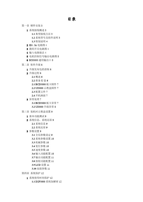
目录第一章硬件安装31系统接线概述31.1典型接线方法31.2系统型号及组件说明31.3特别说明42 KB4.5A电路图43拨码开关电路图44输入电路接法45电机控制信号输出电路图56 BCD3000通用输出口5第二章软件升级61升级发布包的获取62升级过程62.1概述62.2准备U盘62.1 BCD3000板卡固件72.2 UI3000示教盒固件72.3配置文件72.4开机画面73异常处理73.1 BCD3000板卡异常73.2 UI3000升级异常8第三章装机时示教盒设置91基本功能测试92系统信息,系统还原92.1系统信息92.2系统还原93参数设置93.1全局参数设定93.2系统参数设置103.3机械参数103.4复位参数103.5速度参数103.6输入功能配置103.7输出功能配置113.8按钮功能配置113.9 LCD设置113.10高级参数11第四章系统保护121系统使用时间保护121.1 DSP3000系统加解密121.2注册码生成软件121.3注册码生成软件的安装和使用12 2系统设置密码保护13第一章硬件安装1 系统接线概述1.1 典型接线方法如下图所示,为DSP3000W的典型接线图。
1.2 系统型号及组件说明表1:DSP3000系统选型表说明:(1)“*2”表示数量2,”√”或”*1”表示数量1。
(2)BCD3000为运动控制卡,是必配件;BCD3000A、M、S版本间不可互升。
(3)FS3000:包括1602小液晶、转接板、小键盘KB3000(4)UI3000:即示教盒(5)BCL1436:扩展IO板,主要为滴塑、锁螺丝系统等扩展输入输出设计(6)配线:1)C9MF-150,标配,双端磁环,连接UI3000到机器外壳;2)C9MF-060,标配,连接机器外壳到FS3000,或连接FS3000到BCD3000,或连接BCD3000到机器外壳1.3 特别说明(1)“拨码开关”和“FS3000”,只能2选1;且拨码开关须由设备制造商自备。
HCJA含油污水处理机安装、操作、维修手册(1)

目录1.概述 (2)2.适用范围 (2)3.性能特点 (2)4.型号说明 (3)5.技术参数 (3)6.设备系统组成 (4)7.安装说明 (5)8.操作规程 (6)9.注意事项 (17)10.设备故障排除 (18)11.维护与保养 (18)12.废弃物处理 (19)13.附件 (19)1.概述为确保设备的安全使用,所有有关人员在安装和操作前都必须仔细阅读本手册。
本手册包括设备安装、操作和维护方面的重要说明。
本手册是设备供货的一部分。
设备投用前、确保达到设备安全运行必须的条件。
设备的安装、操作和维护应由有资格人员进行。
为确保安全,请不要对设备进行任何修改。
对未经允许就进行修改而导致的损伤,我公司概不负责。
YHCJ一体化污水处理装置是我公司综合考虑多年的含油污水处理经验,成功开发的一种高效、方便、适用范围广的集成式含油污水处理设备,它集成熟先进的多相溶气泵溶气气浮及核桃壳过滤技术于一体,使含油污水处理工程设备化,彻底解决常规流程复杂、设备分散、设备匹配不合理、管路杂乱、施工周期长、运行不方便等缺点,是一种技术先进、性能可靠、维护方便的装置。
2.适用范围港口码头含油污水电厂含油污水石油化工含油污水海洋石油开采陆地石油开采3.性能特点◇工艺流程短,节省投资◇设备自动化程度高,操作方便◇设备一体化,减少大量设计、协调与施工工作量◇占地面积少,节省土建成本4.型号说明YHCJ10A常压式设备处理量10m3/h一体化污水处理装置5.技术参数设计温度:80℃处理量:10m3/h(1) 进水指标含油(mg/L):≤500悬浮物含量(mg/L):≤300进水温度(℃):≤60(2) 出水指标含油(mg/L):<30悬浮物含量(mg/L):≤15(3)设备功率一级提升泵功率: 2.2Kw×2 (配套电机防爆)溶气泵功率: 4Kw×2 (配套电机防爆)刮渣机功率: 0.55Kw (配套电机防爆)二级提升泵功率: 3Kw×2 (配套电机防爆)核桃壳搅拌电机功率4Kw (配套电机防爆)溶药搅拌电机功率:0.55 Kw ×4 (配套电机防爆)计量泵功率: 0.25 Kw×8 (配套电机防爆)反洗电机功率: 3 Kw ×1 (配套电机防爆)空压机: 4 Kw ×1 (配套电机防爆)设备最大运行功率:25 Kw设备装机功率:40 Kw核桃壳过滤器滤料规格及填装数量:核桃壳 1.2~1.6 235Kg整撬运行重量:40 000 Kg整撬外形尺寸(长×宽×高):8400 mm×2300mm×4100mm(不含加药装置)6.设备系统组成a)设备本体● 气浮室气浮溶气技术采用涡流泵,集吸液混合溶气于一体,代替空压机溶气罐组成的溶气释放系统。
普瑞奇滤油机设备介绍、维护及操作手册
3.1 通用安全说明..............................................................................................................5 3. 2 安装位置......................................................................................................................5 3.3 人员安全......................................................................................................................6
8.2.1 油泵进油方式的启动及运行.................................... 24 8.2.2 真空进油方式的启动及运行.................................... 24 8.3 关机............................................................................................................................25 8.3.1 紧急关机.................................................... 25 8.3.2 故障后重启.................................................. 25
天加水冷涡旋式冷水机组安装操作维修手册

◆ 外观漂亮、防腐性强:所有钣金件均经过除锈、清洗、烘干等前处理,然后采用静电喷
塑工艺对每件钣金的内外表面进行喷涂加工,外观美观。喷涂生产线采用德国汉高进口 喷涂设备。
3
天加中央空调
水冷涡旋式冷水机组
三.产品及主要部件介绍
天加水冷涡旋式冷水机组,制冷量从 68.8kW 到 344kW 可选,机组型号从 TWS-201 到 TWS-205,机组采用模块化设计,可根据冷量需要随意组合。本系列产品可匹配天加室内末端 空气处理设备,如变风量空气处理机组、空调箱、风机盘管机组,以满足用户任何使用面积 及不同使用场所的需要。 天加水冷涡旋式冷水机组,所有使用的零部件都是经过严格精心选择的优质零部件,以 提高整个机组的性能,带给客户价值。
4
天加中央空调
水冷涡旋式冷水机组
四.型号、技术参数及外形尺寸
1.型号说明:
T W S 工厂识别码:AA,AB…… 设计序号:A,B,C,D…… 规格:201,202,203,204,205 天加 水冷涡旋式冷水机组
2.技术参数及外形尺寸
机组性能参数表:
型 制冷量 输入功率 能量控制 号 kW kW 启动方式 % 机身颜色 保温材料 压缩机 款式 数量 型式 数量 接头尺寸 推荐总管直径 m3/h 水流量 型式 数量 接头尺寸 推荐总管直径 m3/h 水流量 2 2 R 2” DN50 15.4 2 R 2” DN50 12 TWS-203 TWS-204 TWS-205 206.4 275.2 344 48.9 65.2 81.5 直接启动 0-100%两级 0-100%四级 0-100%六级 0-100%八级 0-100%十级 调节 调节 调节 调节 调节 立柱与控制面板为深灰色,其它面板为灰白色 PE TWS-201 68.8 16.3 涡旋式全封闭压缩机 4 6 8 壳管式冷凝器 4 6 8 R 2” R 2” R 2” DN80 DN100 DN100 30.8 46.2 61.6 高效板式换热器 4 6 8 R 2” R 2” R 2” DN80 DN100 DN100 24 36 48 温度传感器 R22 6 热力膨胀阀 5*6 2940 890 1700 3*460 3 10 10 R 2” DN125 77 10 R 2” DN125 60 TWS-202 137.6 32.6
装维人员日常工作手册

用于连接内网和外网,实现网络互连互通 。
工具与设备的维护保养
01
定期检查工具和设备的 完好性,确保其正常工 作。
02
使用后及时清洁工具和 设备,保持其清洁卫生 。
03
根据需要进行润滑或更 换易损件,保证工具和 设备的正常运转。
04
定期对工具和设备进行 保养,延长其使用寿命 。
04
CATALOGUE
3
跨部门合作与交流
鼓励装维人员与其他部门进行合作与交流,了解 公司整体运营情况,提高自己的综合素质。
THANKS
感谢观看
安全操作规范
高处作业安全规范
总结词
在高处作业时,应采取必要的安全措施,确保作业人员的安全。
详细描述
在高处作业时,应佩戴安全带、安全帽等防护装备,并使用合适的脚手架、梯子等工具。作业前应对作业环境进 行评估,确保没有安全隐患。同时,应遵循“先检查后作业”的原则,确保所有安全措施到位后再进行作业。
带电作业安全规范
。
02
CATALOGUE
日常工作流程
接单与派工
接单
接收来自客户或上级的报修请求,了 解并记录故障情况、报修人信息和联 系方式。
派工
根据报修请求的紧急程度、地理位置 等因素,合理安排维修人员,确保及 时响应。
现场作业准备
准备工具
根据维修需要,准备相应的工具和备件,确保作业顺利进行 。
核实信息
与报修人再次确认故障情况,核实地址、联系方式等信息, 确保无误。
交流与分享
参加外部培训后,应组织内部交流与分享,将所学知 识传递给其他同事,促进团队共同进步。
在职学习与交流
1 2
自主学习
鼓励装维人员在工作中自主学习,通过阅读技术 文档、在线课程等方式不断提高自己的专业水平 。
Baldor 马达安装、维护和操作手册说明书

1WARNING: Because of the possible danger to persons(s) or property from accidents which may result from the improper use of products, it is important that correct procedures be followed: Products must be used in accordance with the engineering information specified in the catalog. Proper installation, maintenance and operation procedures must be observed. The instructions in the instruction manuals must be followed. Inspections should be made as necessary to assure safe operation under prevailing conditions. Proper guards and other suitable safety devices or procedures as may be desirable or as may be specified in safety codes should be provided, and are neither provided by Baldor Electric Company nor are the responsibility of Baldor Electric Company. This unit and its associated equipment must be installed, adjusted and maintained by qualified personnel who are familiar with the construction and operation of all equipment in the system and the potential hazards involved. When risk to persons or property may be involved, a holding device must be an integral part of the driven equipment beyond the speed reducer output shaft.DODGE ® Instruction Manual for Type K and DOUBLE-INTERLOCK ®Pillow Blocks & S-1 UnitsThese instructions must be read thoroughly before installation or operation. This instruction manual was accurate at the time of printing. Please see for updated instruction manuals.WARNING: To ensure that drive is not unexpectedly started, turn off and lock out or tag power source before proceeding. Failure to observe these precautions could result in bodily injury.WARNING: All products over 25 kg (55 lbs) are noted on the shipping package. Proper lifting practices are required for those products.FITTING OR REPLACING A UNIT IN A PILLOW BLOCK1. Up to 5” bore, match marks have been stamped on themating faces of the cap and base of each outer housing. Over 5” bore match mark cap and base of each outer housing before removing cap. When reassembling pillow block make sure match marks on cap and base match.2. Lubricate bearing seat on the cap and on the base of theouter housing with an anti-seize compound.3. Fit each unit to its outer housing before carrying out step7. Place the unit in the pillow block base and install cap. Tighten cap bolts to specified torque in Table 1.Table 1 – Cap Bolt Torque (Non-Expansion & Expansion)Bore Size (In.)2 Bolt Base 4 Bolt Base Bolt SizeTorque Ft.-Lbs. Bolt Size Torque Ft.-Lbs. 1-3/16 – 1-11/16 3/8 – 16 24 – 30 — — 1-15/16 – 2-3/16 7/16 – 14 40 – 50 — — 2-7/16 – 2-1/2 1/2 – 13 60 – 75 1/2 – 13 60 – 75 2-15/16 – 3 5/8 – 11 120 – 150 5/8 –11 120 – 150 3-7/16 – 3-1/2 3/4 – 10 208 – 260 3/4 –10 208 – 260 3-15/16 – 4 — — 3/4 – 10 208 – 260 4-7/16 – 4-1/2 — — 7/8 – 9 344 – 430 4-15/16 – 5 — — 1 – 8 512 – 640 5-7/16 – 6 — — 1 – 8 512 - 6406-7/16 – 7——1 - 8512 - 6404. Add or remove shims between cap and base as requiredto obtain “snug” fit of unit in outer housing with cap bolts tightened to specified torque in Table 1.5. Check fit by prying against lubrication stud in unit throughthe lubrication hole in housing cap with a screwdriver or small pinch bar depending upon the size of the pillow blocks.6. The “snug” fit becomes a matter of judgment. A “loose orsloppy” fit may allow a unit mount to move in its outer housing thus wearing the mating surfaces. Too “tight” a fit will not allow the unit to move and compensate for misalignment and for shaft deflection caused by belt pull and dead weight.7. Install bearings per installation instructions contained in thismanual.INSTALLATION INSTRUCTIONS1. Shaft must be clean, free of burrs and lubricated. File nicksfrom housing bases.2. Loosen setscrews in collar and slide bearings on shaft. Ifforce is necessary, tap inner race only with a light drift. For vertical applications, locate adjusting nut on bearing so nut faces upward.3. Position expansion (floating) pillow block on mountingsurface and tighten base hold-down bolts.4. Position non-expansion (fixed) pillow block in correct relationto shaft and mounting surface. Tighten base holddown bolts, then torque setscrews in collar per Table 2.5. The effort required to turn the shaft should be the samebefore and after bolting bearings to the support.Table 2 – Set Screw TorqueBore Size (In)Set Screw Size (In)In-Lbs 1-3/16 – 1-11/165/161651-3/4 – 2-1/23/82902-11/16 – 3-1/21/26203-15/16 – 55/813255-7/16 – 63/421506-7/16 – 77/851306. Mount a dial indicator on the shaft near the nonexpansion(fixed) bearing. Place the indicator probe so that it contacts the machined surface of the S-1 Unit Housing perpendicular to that surface. See sketch below. Only one face of the S-1 Unit is a machined face.Figure 1 - S-1 Unit7. Zero the indicator and sweep the machined face 360°,noting the total indicator turnout (TIR).8. If the TIR is less than or equal to the value shown on Table3, tighten the housing cap bolts per Table 1.9. If the TIR is greater than shown on Table 3, gently tap themachined face of the S-1 housing until the TIR is less than or equal to the value shown on Table 3. Then torque the housing cap bolts per Table 1. Sweep machined faces again to verify that the TIR is still less than or equal to the value shown on Table 3.P .O. Box 2400, Fort Smith, AR 72902-2400 U.S.A., Ph: (1) 479.646.4711, Fax (1) 479.648.5792, International Fax (1) 479.648.5895Dodge Product Support6040 Ponders Court, Greenville, SC 29615-4617 U.S.A., Ph: (1) 864.297.4800, Fax: (1) 864.281.2433All Rights Reserved. Printed in USA.06/15 Litho 20,000© Baldor Electric Company MN3037 (Replaces 499798)*3037-0615*Table 3 – Total Indicator Run-out (TIR)Shaft Size (Inches)TIR (Inches)1-3/16 – 1-7/16 0.00301-1/2 – 1-11/160.00351-3/4 – 2 0.00402-3/16 0.00402-1/4 – 2-1/2 0.00452-11/16 – 3 0.00553-3/16 – 3-1/20.00653-15/16 – 4 0.00704-7/16 – 4-1/2 0.00804-15/16 – 50.008510. The non-expansion (fixed) bearing is now installed. Move tothe expansion (floating) bearing.11. Locate expansion unit in center of its axial travel or atextreme if maximum expansion is required (do not preload stop pin) and torque collar setscrews (52) per Table 2.12. Do not install external grease fittings until completion of finalsteps below.13. Torque setscrews of expansion unit (Table 2).14. Repeat Steps 6, 7, 8 and 9 for the expansion bearing.15. The expansion (floating) bearing is now installed.LUBRICATION GUIDELINESThis bearing is factory lubricated with a lithium or lithium complex base grease which is suitable for most applications. However, extra protection is necessary if the bearing is subjected to excessive moisture, dust, corrosive vapor or other harsh environments. In these cases, the bearing should contain as much grease as speed will permit (a full bearing with consequent slight leakage through the seal is the best protection against contaminant entry).For relubrication, select a grease that is compatible with a lithium or lithium complex grease. The following table is a general guide for normal operating conditions. However, some situations may require a change in lubricating periods as dictated by experience.Normal Operation — This bearing has been greased at the factory and is ready to run. The following table is a general guide for relubrication. However, certain conditions may require a change of lubricating periods as dictated by experience. See “High Speed Operation” and “Operation in Presence of Dust, Water or Corrosive Vapors” above.High Speed Operation — High speed operation is 70% of maximum catalog speed and above. In the higher speed ranges too much grease will cause overheating. The amount of grease that the bearing will take for a particular high speed application can only be determined by experience — see “Operating Temperature” below. If excess grease in the bearing causes overheating, it will be necessary to remove grease fitting (also drain plug when furnished) to permit excess grease to escape. The bearing has been greased at the factory and is ready to run. When establishing a relubrication schedule, note that a small amount of grease at frequent intervals is preferable to a large amount at infrequent intervals.Operation in Presence of Dust, Water or Corrosive Vapors — Under these conditions the bearing should contain as much grease as speed will permit, since a full bearing with consequent slight leakage is the best protection against entrance of foreign material. In the higher speed ranges too much grease will cause overheating — see “High Speed Operation” above. In the lower speed ranges it is advisable to add extra grease to a new bearing before putting into operation. Bearings should be greased as often as necessary (daily if required) to maintain a slight leakage at the seals.Operating Temperature — Abnormal bearing temperature may indicate faulty lubrication. Normal temperature may range from a few degrees up to 100ºF above ambient, depending on bearing size, speed, loading and environmental conditions. Unusually high temperature, in this range, accompanied by excessive leakage of grease indicates too much grease. In the circumstance that there is excess grease in the bearing, remove the grease fitting to allow the excess grease to purge. When purging ceases, wipe excess grease with a clean rag and screw fitting back into the bearing. High temperature with no grease showing at the seals, particularly if the bearing seems noisy, usually indicates too little grease. Normal temperature and a slight showing of grease at the seals indicate proper lubrication.Table 4 – Lubrication Guide Read Preceding Paragraphs Before Establishing Lubrication ScheduleHours Run per Day Suggested Lubrication Period In Weeks 1 to 250RPM 251 to 500RPM 501 to 750RPM 751 to 1000RPM 1001 to 1500RPM 8162412121012751053742521Lubrication recommendations are intended for standard products applied in general operating conditions. For modified products, high temperature environments and other anomalous applications, contact product engineering at 864.284.5700.Kind of Grease — Many ordinary cup greases will disintegrate at speeds far below those at which DODGE bearings will operate successfully if proper grease is used. DODGE bearings have been lubricated at the factory with an NLGI #2 lithium complex base grease. Relubricate with lithium complex-base grease or a grease which is compatible with original lubricant and suitable for roller bearing service. In unusual or doubtful cases the recommendation of a reputable grease manufacturer should be secured.Storage or Special Shutdown — If exposed to wet or dusty conditions or to corrosive vapors, extra protection is necessary. Add grease until it shows at the seals; rotate the bearing to distribute grease; cover the bearing. After storage or idle period, add a little fresh grease before running. During long idle periods, rotate shaft at least once a month.Special Operating Conditions — Refer acid, chemical, extreme or other special operating conditions to Baldor Electric Company.。
DYRC系列空气预热器安装、维护及操作手册(英语)

DYRC系列空气预热器安装、维护及操作手册Installation, Maintenance and Operation Manual of DYRC Air Preheater Series 1. 安装Installation1.1 空气预热器在安装前应检查管箱外形尺寸,并应清除管子内外的尘土、锈片等杂物,检查管子和管板的焊接质量,必要时进行渗油试验检查其严密性。
Prior to installation, please check the overall dimensions of the tube-box and remove dust, rusty debris and the similar inside and outside the tubes. Check the welding quality of the tubes and tube plate and check the tightness by oil penetration test if necessary.1.2 空气预热器吊装须使用吊挂横梁上的吊装空试吊平稳后,装入钢结构框架内。
In the course of air preheater lifting, conduct trial lifting with handling holes on the lifting beam. When all is stable, place the preheater into the steel framework.1.3 吊挂横梁与钢结构框架结合部须填充保温材料用作密封。
Fill heat insulation material where lifting beam and steel framework connect for the purpose of sealing .1.4 空气预热器安装到位后,中间横梁与钢结构框架焊接牢固,并除掉临时筋板。
氢气压缩机安装维护手册第1册
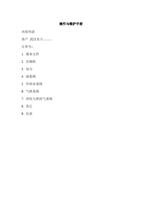
操作与维护手册内容列表客户武汉东立。
订单号:1.基本文件2.压缩机3.动力4.油系统5.冷却水系统6.气体系统7.净化与密封气系统8.其它9.仪表1.基本文件1.1安装、操作与维护手册BA 901228 rev00 NEAD1.2p&I –Diagrams1.3总装图1.4 基础平面图1.4.1锚定1.4.2 物量推动力计算1.4.3 起始扭矩曲线1.4.4基础固定1.4.5 水平校准轴清单1.5 实用消耗单2.压缩机3.2.1 首要的安全规则2.2包装、运输、安装与装配2.3压缩机部件2.3.1 压缩机手册2.3.2 剖面图2.3.3 备用部件清单2.3.4 进口阀1st安装底座直径1102.3.5 出口阀1st安装底座直径1102.3.6进口阀减荷器2.3.7压缩机阀门维修指南2.3.8 填料介质2.3.9 活塞杆件密封2.3.10 主油泵2.3.11 油位指示器2.3.12 中间套管系统2.3.13 超螺母活塞螺帽固定3动力3.1主马达3.2飞轮护罩4 油系统4.1总布置4.2组件4.2.1电油泵单元-马达-联轴器4.2.2油冷却器4.2.3油过滤器4.2.4温度控制阀4.2.5压力安全阀4.2.6压力控制阀4.2.7阀门与过滤器4.3 加热器-曲柄箱加热器-电平开关4.4 油管连接组件单与管道供应概述和isometric 4.5润滑油建议4.6 预润滑油线连接图5 冷却水系统5.1 冷却水管道系统-概述和isometric5.2 元件5.2.1 视镜5.2.2 手动阀5.2.3 安全阀6 气体系统6.1 气体管线系统-组件清单和管道供应-概述和isometric(等角的/立体布置图)6.2 吸入管过滤器6.3 孔口6.4 脉动缓冲器6.5 冷却器6.6带破裂片(安全隔膜)的安全阀6.7止回阀6.8气体管道吹扫步骤6.9 氮气密封性检验步骤7 净化与密封气系统7.1净化气隔板-概述与isometric7.2气体排空packing组件清单和管道供应概述和isometric7.3 净化气和密封气系统隔板连接7.4 排气吸气阀hook up vent gas suction valve unloaders8 其它8.1 jackcrews8.2 管钳夹8.3 管接头8.4 chemical Dowels9 仪表9.1仪表清单9.2仪表连接图9.3W iring diagram9.4逻辑图9.5仪表架和就地表盘布置图Instrument rack and local panel layout9.6耗电单9.7框图9.8仪表材料9.8.1测压计9.8.2温度计9.8.3热阻测量计9.8.4压力变送9.8.5热阻测量计9.8.6 电磁阀9.8.7 转子流量计9.8.8压力控制阀9.8.9行程开关9.8.10振动开关9.8.11 接线盒9.8.12电缆密封套氢气混合气压缩机前言这部分操作指导包括关于德国诺尔曼·艾索有限公司提供的标准工艺气压缩机安装、操作和维护信息。
GR10、DR10 单罐固定床软化阀 安装、使用、维护手册说明书
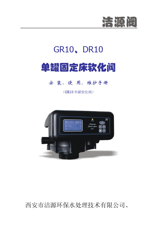
GR10、DR10单罐固定床软化阀安 装、使 用、维护手册(GR10单罐软化阀)西安市洁源环保水处理技术有限公司、一、控制原理(参见产品样本)Ⅰ 液晶显示控制器前面板各种操作显示说明流量模式“”显示界面当前工位:再生S:0200:设定再生用水量,由进水流量计计量,通过射流器的水量相当于8—10%浓度的盐水;D:0200:递减状态,到零切换;00.00t/h ;当前每小时进水量00000.0t :阀体长期累计通水量当前工位:清洗S:0200:设定清洗用水量,由进水流量计计量D:0200:递减状态,到零切换到软化; 00.00t/h ;当前每小时进水量 00000.0t :阀体长期累计进水量当前工位:软化S:0200.0:设定周期软化水量,由进水流量计计量D:0200.0:递减状态,到零切换到再生;00.00t/h ;当前每小时进水量00000.0t :阀体长期累计进水量操作按扭::手动转位;:参数设定;:移位;:加1A ”和“”已开。
B 、闭锁:设备无任何操作3分钟后,自动闭锁。
C 、模式切换:开锁状态下,操作按扭在时间模式“”D、 手动转位:开锁状态下,按此按钮多路阀切换到下一工位。
E、 参数设定:开锁状态下,按此按钮屏幕出现参数设定界面,确认和退出:数字移位G、:数字加1时间模式“ ”显示界面当前工位:再生当前工位:清洗当前工位:软化时间模式“ ”参数设定二、输入输出控制说明1、互锁线的连接如下图所示图1:互锁线路2.外部控制接口该阀可以通过外部其他控制系统控制进入、或RUN状态,外部控制系统给出的电压信号等同于按了一下手动转位()按钮。
图2:外接控制线路3.继电器输出接口⑴.继电器的接点容量为5A/250V。
⑵.继电器输出端口中,NO为常开端,COM为公共端,NC 为常闭端。
⑶.在连接继电器输出时,AC220V电源输入端需接漏电断路器。
不同模式下,继电器输出NO与COM,接通为“C”,断开为“×”, 有条件断开为“C×”模式 再生 清洗 运行 转位0 C C C×1 C C××2 ××C×3 C C× C×4 C C C××模式 应用场合0 进水电磁(动)阀模式:设备进水阀,转位泄压,关闭控制阀时关进水。
GT执行机构安装维护手册

位置决定。 l 把驱动套及 4 个固定螺栓一起插入中间柱体里面。
4
GIANT TORK INC.
执行机构安装维护手册
6.2. 驱 动 套 和 阀 杆 之 间 的 连 接 GEQ 执行机构基础法兰的机加工符合 ISO 5211/1 标准。阀门&执行机构都能够使用连接 器高强度黄铜加工----蜗轮。 (2)手动 手轮在正齿轮时,用蜗轮机构趋动。 手动增速齿轮:GEM-01 是 2 段/GEM-04 时是 1 段或 2 段。 4)限位开关 (1)因计数器机构方式可靠性高,安装简便(1 回转充分) (2)开关采用小型微动开关
A.国外主要也采用微型开关。 B.凸轮开关,因扭矩过大不产生捕捉动作,有必要 a、b 接点重叠。 C.采用微动开关时,齿轮扭矩巨动,齿轮可能变形。 (3)以点动式设定
粘结标签的是内接线片,外接线片位于两个制动螺栓之间。)确保电源电压满足铭牌上的
规定。
3.3 密封电缆入口(3/4”NPT)
即使在不用时,所有管道入口也必须密封。
4.行程限位开关装置
4.1 关闭限位开关装置 1) 拉动分离杆,并且沿顺时针方向转动手轮,使阀门处于“全关”状态。 2) 使用内六角扳手,把下游凸轮上的螺钉拧松(关闭限位开关)。 3) 调整凸轮至限位开关,卡卡两声响,表示已经完全断开下游限位开关,然后拧紧 螺钉。
2.2 阀门位置指示 执行机构顶端的显示器显示了阀门位置是“开” (open)或者“关”(close) 。
2
GIANT TORK INC.
执行机构安装维护手册
使用及维护手册
第一章 概 述有多年电梯制造经验的蒂森电梯公司设计和生产绝对安全、经济、舒适的电梯。
请仔细阅读该资料。
这里描述了用户的任务及职责。
请注意,如果用户忽略了这些职责,则会失去要求质量保证的权利,并需承担相应的风险。
如果您有关于安装安全、操作及维护方面的问题,请与“蒂森电梯有限公司”联系。
1.1 电梯的结构如图1所示。
1.2 电梯的使用和维护,始于电梯安装完毕和正式验收之后。
1.3为确保电梯的安全行驶,必须建立正确的维护保养,管理制度: ① 每周对主要安全设施和电气控制部份进行一次检查;机械部份的检查和润滑。
② 每隔三个月对其较重要的机械和电气设备进行细致的检查、调整和维修。
③ 每年组织有关专业人员,进行一次技术检验,检查所有机械、电气、安全设施的工作状况;修复、更换磨损严重的零、部件。
④ 根据使用情况,可在三至五年内,进行一次全面的拆卸清洗检修和更换重要的机械、电气部件。
⑤ 根据电梯运行性能和使用率,来确定大修期限。
⑥ 每年检查一次电气设备的金属外壳接地或接零装置。
⑦ 每年检查一次电气设备的绝缘电阻。
⑧ 发现有异常现象时,应立即停驶,详细检查修复后方可使用。
⑨ 电梯停用七天以上时,须经详细检查并试运行1小时后,方可投入正常使用。
⑩ 平时应将发生的故障、检查经过、维修的过程作详细的记录。
1.4维修人员须经蒂森公司培训的专职人员对电梯进行经常性的管理、维护和检修,进行维修操作的维修人员还须取得当地劳动安全部门颁发的“电梯维修保养安全操作证”。
1.5 电梯司机须由取得上岗操作证者担任;应具有高度的责任心,爱护设备,熟练掌握使用方法。
1.6 电梯正常工作条件,应符合电梯技术条件中的有关规定。
1.7安全符号及定义为了更好地理解定义,各安全符号的说明如下:符号说明危险: 该符号提醒人们注意高度危险的人身伤害,必须随时遵守。
警告: 该符号表示一种信息,如果不遵守该符号,可能会导致人员伤害或严重的财产损失,必须随时遵守。
C602使用说明书v203安装维护手册(全)

XK3190-C602称重显示控制器使用说明书安装维护手册(完全版)(2.03版)上海耀华称重系统有限公司制造目录前言 (1)第一章概述 (3)第二章主要参数 (4)第三章安装与接线 (7)3.1仪表前、后面板示意图 (7)3.2主板、电源板示意图 (9)3.3仪表的安装 (11)3.4传感器与仪表的连接 (12)第四章标定 (13)4.1标定方法 (13)4.2标定数据检查与修改 (14)第五章通用类参数设置及操作 (16)5.1 参数设置简述 (16)5.2 参数初始化 (17)5.3参数设置时的键功能说明 (17)5.4仪表常用操作说明 (22)第六章定量秤操作说明 (24)6.1定量秤概述 (24)6.2定量秤控制参数设置 (26)6.3定量秤操作举例 (28)6.4定量秤控制过程描述 (30)6.5查询累计数据 (38)第七章分选秤操作说明 (40)7.1分选秤概述 (40)7.2分选秤控制参数设置 (41)7.3分选秤控制过程描述 (42)7.4分选秤操作举例 (49)7.5查询累计数据 (51)附录A 错误提示信息与常见问题处理 (53)附录B 大屏幕显示器接口 (57)附录C 通讯口数据格式 (59)附录D 打印接口及打印格式说明 (79)附录E 控制与模拟量输出接口 (89)附录F 继电器盒的使用说明 (92)附录G 安全说明 (94)前言本手册的使用说明本手册是供XK3190-C602仪表的使用操作人员和安装调试人员使用的完全版安装维护手册。
设备操作人员可使用C602仪表的《设备操作手册》。
使用本手册时,可以先粗略地翻看一下,先重点读与您当前工作最相关的内容,暂时不需了解的内容可以跳过去,对仪表有初步的了解后再进一步全面细读。
当遇到仪表工作不正常或提示出错信息时,可查阅附录A,判断原因,进行相应的处置。
当遇到设备工作不正常,停在某一状态不再继续运行时,请参阅本说明书第六章或第七章,将辅助显示器设置为程序步状态,对照相应的程序步描述表,看设备停止在哪一步上,分析该步继续向下运行的条件是什么,检查哪些条件不满足,然后进行相应的处置。
Server服务器安装维护手册
windows2000 server服务器操作系统安装维护图文手册一、准备工作:1.准备好Windows 2000 server简体中文版安装光盘。
2.一张系统SP4补丁盘。
3.一张空白的软盘。
4.准备好HP SmartStart V ersion 7.40光盘。
5.用纸张记录安装文件的产品密匙(安装序列号)。
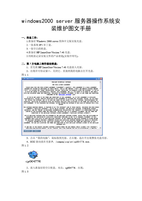
二、第3方电脑上制作驱动软盘:1、首先将HP SmartStart V ersion 7.40光盘放入光驱。
2、出现许可协议窗口,关闭它。
直接到我的电脑去打开光盘。
图1.13、点击“我的电脑”,鼠标指到光驱,点右键,选打开出现整张光盘内容。
4、SCSI驱动放在光驱F:/compaq\csp\nt\cp004776.exe。
图1.25、放入准备好的空白软盘,双击:cp004776。
出现:图1.36、点击“Extract”选择解压路径,我们选择A:盘,点“确定”,驱动开始解压。
图1.47、解压完毕,我们到软盘上去确定下,驱动是否解压完成图1.58、整张驱动软盘制作完毕。
三、设置用光盘启动系统:1、启动电脑,当出现F9时,按F9键进入BIOS设置界面。
2、选择[CDROM](光盘启动)。
3、按F10(保存退出)回车。
将Windows 2000 Server安装光盘放入光驱,重新启动系统并把光驱设为第一启动盘,即可见到安装界面。
四、安装Windows 2000 server步骤:1、选择安装Windows 2000 server,同时记录下Windows 2000 server的序列号:H6TWQ-TQQM8-HXJYG-D69F7-R84VM记录后按“2”键,安装Windows 2000 server,出现:图1.1当安装界面下方出现“Press F6 if you need to install a third party SCSI or RAID driver...”字样的时候,快速点击“F6”(关键步骤)。
智慧教学系统安装及操作手册说明书

Smart Classroom System智慧教学系统 Installation and Operating Manual安装及操作手册V 1.0重要的安全说明重要的安全说明1. 在安装和使用设备前请先仔细阅读本安全操作规程。
2. 请保存好您的安全操作指南便于以后作参考用。
3. 请遵守所有设备操作指南中的“警告”事项。
4. 须遵守各项操作指南中的规章原则。
5. 清洁设备:清洁设备之前,请先关掉电源,从插座中拔出设备插头,将各连接的系统单元拆卸出来,清洁时请用干燥的软布擦拭。
6. 未经生产厂家同意,不要使用任何不匹配的附件配置,这都有可能引起危险事故。
7. 勿将设备置于潮湿或靠近热源的地方,以免发生危险。
8. 设备不应遭受水滴或水溅,不应放置诸如花瓶一类装满液体的物品。
9. 电源插头作为断接装置,应便于操作。
10. 设备应可靠连接到带保护接地的电网电源输出插座上。
11. 勿将设备放置在不稳固的台面上;在运输过程中避免设备遭受强烈振动而引起损坏,建议在运输前选用合适的包装或使用原包装。
12. 请勿阻塞设备上的通风开口,并保持室内的空气通畅,便于设备的维护。
13. 供电电压:AC 100 V-240 V 50 Hz/ 60 Hz14. 设备连接所需要的延长电缆线请绕道穿行,勿有重物挤压,这样能有效维护系统的正常工作。
15. 每套系统中所连接的接收器不得超过规定数量,否则可能会导致整个系统中设备的异常工作,如有特殊要求请与距离您最近的深圳台电售后服务中心取得联系。
16. 确保设备不被任意拆开机壳,也不允许任何硬质导体或液态物质残留在机壳内。
17. 设备有需要维护时,不要自行拆卸,请及时与距离您最近的深圳台电售后服务中心取得联系。
18. 所有TAIDEN产品将提供一定期限(详见保修卡)免费保修,但人为损坏除外,例如:A. 设备因人为作用被摔坏;B. 因操作员操作不当而导致设备受损;C. 自行拆卸后而导致部分设备零件受损或丢失。
利德华福变频器安装调试及维护手册
编号:BLH B01-070.6版本号:V.01HARSVERT系列变频调速系统安装调试及日常维护北京利德华福电气技术有限公司通讯地址:北京市昌平区阳坊镇阳坊工业南区北京利德华福电气技术有限公司邮政编码:102205电话:010-********传真:010-********一安装说明 (4)1.1 安装前的准备工作 (4)1.1.1现场清点货物 (4)1.1.2卸车 (4)1.1.3 存储 (4)1.1.4 安装环境 (4)1.1.5 地基 (5)1.2 机械安装 (6)1.2.1拆箱 (6)1.2.2柜体就位 (6)1.2.3 功率单元安装 (7)1.2.4风机及报警器安装 (8)1.3 电气连接 (10)1.3.1 变压器试验 (10)1.3.2 变压器柜接线 (10)1.3.3 功率柜接线 (12)1.3.4 风机及报警器的接线 (14)1.3.5柜间连线连接 (14)1.3.6变频器对外接口的连接 (15)1.3.7检查 (17)二系统调试 (19)2.1控制系统调试 (19)2.1.1调试前准备工作 (19)2.1.2送控制电 (19)2.1.3“参数”设置 (19)2.1.4“功能”参数设置 (20)2.1.5模拟量量程设置 (20)2.1.6控制系统调试 (21)2.1.7模拟带高压调试 (21)2.1.8与现场开关柜联锁 (22)2.2高压调试 (23)2.2.1上高压前检查 (23)2.2.2高压送电实验 (23)2.2.3投入运行 (24)2.3 矢量控制型变频器参数调试 (25)2.3.1变频器驱动异步电机 (25)2.3.2变频器驱动同步电机 (29)三常见故障处理 (33)3.1 轻故障分类与报警 (33)3.2 重故障分类与报警 (34)3.3变频器轻故障 (35)3.3.1 UPS输入掉电;直流电源掉电 (35)3.3.2 功率单元旁路(单独选购) (35)3.3.3变压器轻度过热 (36)3.3.4模拟给定掉线 (36)3.3.5控制器无响应 (36)3.3.6柜门未关严 (37)3.3.7现场报警输入有效 (37)3.4变频器重故障 (38)3.4.1变压器严重过热 (38)3.4.2 负载过载、负载过流、变频器过流 (38)3.4.3 功率单元重故障 (38)3.5 如何更换故障单元 (39)3.6 其他常见问题 (39)3.6.1不能调整运行频率 (39)3.6.2高压变频调速系统不能开机 (39)3.6.3故障时没有音响报警 (40)3.6.4报警但界面没有指示 (40)四变频调速系统的日常维护 (41)附录 (44)安全约定HARSVERT系列高压变频调速系统在设计时已充分考虑了安全问题,然而,它作为一种高压设备,设备内部及其连接电缆带有危险的高电压,同时因长时间运行发热,一些部件温度升高,直接触摸会灼伤人体。
安装、操作和维护手册说明书

Installation and Operation Manual Installation, Operation and Maintenance Manual DFOE3, DFOE4, DFOE6Throughout this manual statementsindicating precautions necessary to avoid equipment failure are referenced in a Note. Statements indicating potential hazards that could result in personal injury or property damage are referenced in a CAUTION! box.Donaldson Company reserves the right to change designand specifications without prior notice.Illustrations are for reference only as actual product mayvary.IOM AK0302801Revision1 DFOE4DFOE3 DFOE6唐纳森(无锡)过滤器有限公司Donaldson (Wuxi) Filters Co.,Ltd.Warning – Improper operation of a dust control system may contribute toconditions in the work area or facility that could result in severe personal injury and product or property damage. Check that all collection equipment is properly selected and sized for the intended use.DFOE3,4,6 Table of contents List of figures1.0 Product Introduction …………………….6 Figure 1: Schematic2.0 Installation……………………………….6 Figure 2: Operational Schematic3.0 Start up and Operation …………………7 Figure 3: Inlet Schematic4.0 Service …………………………………...8 Figure 4: Dust Removal for Dust DisposalSystem5.0 Trouble Shooting ………………………...9 Figure 5: Exchanging Filter Element6.0 Control Panel ……………………………11 Figure 6: Control Panel7.0 Spare Parts ………………………………15 Figure 7: Electrical Terminal BlockFigure 8: Wiring DiagramData SheetModel Number __________________________Serial Number_____________________________ Ship Date _______________________________Installation Date __________________________ Customer Name________________________________________________________________ Address _______________________________________________________________________ _______________________________________________________________________ Filter Type _____________________________________________________________________ Accessories_____________________________________________________________________ Other _________________________________________________________________________唐纳森(无锡)过滤器有限公司Donaldson (Wuxi) Filters Co.,Ltd.DFOE4DFOE3Figure 1 Schematic1. Lift bar2. Filter access cover3. Dust bin4. Control panel5. Access door6. Inlet7. Access panel for cleaning 8. Fan outlet9. Power supply cable inlet 10. Compressed air inletDFOE 3,4,6*Figure 2Operational SchematicOperation Filter element cleaning 4. Clean air outlet 5. Manifold 7. Tube sheet 1.Dirty air inlet唐纳森(无锡)过滤器有限公司Donaldson (Wuxi) Filters Co.,Ltd.1.0 Product Introduction The dust collector is used for the collection of airborne dust and particulate. Whether in answer to the problem of air pollution, or as part of a manufacturing process, the dust collector provides highly efficient and continuous on-line dust collection. The filter elements are the heart of the dust collector. These filter elements help ensure the only cleaned air is returned to the plant environment. During operation, contaminated air enters the dust collector through the dirty air inlet area and passes through the filter elements. Dust is collected on the surface of the filterelements. The filtered air flows through the centre of the filter elements into the clean air chamber, where it exhausts through the clean air outlet re-circulated into the environment. To ensure the optimal performance of your dust collector it is necessary that the filter elements are cleaned automaticallysequentially. During the filter sequence, the timer energizes a solenoid valve, causing the corresponding diaphragm valve to send a pulse of compressed air through the filter elements (from the inside outwards),removing the collected dust from the outside surface of the filter elements. The dust falls through the hopper into the dust disposal system.2.0 InstallationEnsure all persons carrying out work on thesupplied equipment follow any relevant recognized standards or codes and are competent to do so.2.1 Compressed Air ConnectionCompressed air pressure must be at 6 bar. Be sure that all compressed air components are adequately sized to meet the maximum system requirements of 45 Nliters per pulse at 6 bar supply pressure (= design pressure).Compressed air supply has to be both oil and moisture free.Connect the compressed air supply line to the compressed air connection of the dust collector.A compressed air shut-off valve, a filter/water separator with automatic condense drain, a pressure regulator with gage must beinstalled on the compressed air supply line.2.2 Electrical ConnectionEnter the cable through the cable gland locate at the lower right corner of thecollector. And enter the cable to the control box through the cable gland locate at the bottom of the enclosure. Please follow the electrical diagram provided for connection. Do not install in classified hazardousatmospheres without an enclosure rated for the application.DFOE 3,4,6Figure 3 Inlet Schematic2.3 Inlet Duct ConnectionThe inlet collar is integrated with the unit, it isshown on figure 3.3.0 Start-up and OperationCheck that the outlet of the fan is free of debris before starting.Make sure the dust disposal system is properly installed under the hopper.With new filter elements the airflow should be adjusted to the nominal value by closing the damper valve.Check if the access doors are closed. Switch main power on and press switch ’start’.Adjust the damper to the desired airflow. Turn on the compressed air supply. Adjust to 6 bar of pressure with the compressed air regular.The cleaning cycle only starts whennecessary. For customized setting see the controls manual.唐纳森(无锡)过滤器有限公司Donaldson (Wuxi) Filters Co.,Ltd.Figure 4Dust Removal for Dust Disposal SystemFigure 5Replacing of Filter ElementsWhen replacing diaphragm assembly make sure the marking "THIS SIDE OUT" ondiaphragm assembly faces valve bonnet and that bleed hole in diaphragm assembly is in alignment with cavity in valve body and bonnet. The external contours of thediaphragm, body and bonnet must all be in alignment.Replace bonnet bolts and tighten in a criss-cross manner.4.2 Replacing of Filter ElementsCaution :When the airflow is low or the differential pressure is too high and alarm, must change the filter elements. After operating more than 2000—4000 hours continuously, must change the filter elements.All filter elements should be changed at the same time.Do not drop the new filter element on the floor or any other hard surface. It isnecessary to clean the dust of the tube sheet all around the opening to ensure a positive seal of the gasket.Slide the new filter element along the yoke with the gasket end facing inward towards the clean air chamber.Reinstall the cover and screw the wing nut clockwise onto the yoke. Tighten securely, to prevent leakage.DFOE3,4,6 5.0 Trouble shooting唐纳森(无锡)过滤器有限公司Donaldson (Wuxi) Filters Co.,Ltd. Fan does not startNot wired correctly.Check and correct internal motor wiring forproper connections for your voltage (see Wiring Diagram)Proper wire size not used for motor Rewire per national and local electric codes for proper wire size. Fan set starts, butdoes not keep running Incorrect overload protection is installed Check for proper motor overload protection. Reset or replace if needed for proper value.Dust collector doors are open or not closed tight Tighten doors securely.Hopper open to atmosphereInstall dust bin under hopper and seal the access door securely.Damper valve not adjusted properlyCheck airflow in ducting for properrequirements. Adjust the damper valve until the proper airflow is achieved. Do not attempt to run without inlet ducting attached.Electrical circuit fusesCheck if the supply circuit has sufficient power to run all equipment. Excessivenoise/vibration of the fanIf thishappens, it should be rectified at onceDust deposit on the blades Clean the blades.Worn blades The fan wheel has to be replaced. Worn bearingsThe bearings have to be replaced.Dust emissionFilter elements installed improperlyCheck that gaskets on the filter element(s) are firmly pressed to the tube sheet (the wing nuts of the filter elements should befully tightened by hand).Filter element damage, dents in the end caps, gasket damage or holes in pleated media Replace the filter elements.Doors not airtightTighten doors securely and check sealing.DFOE3,4,6Insufficient airflow Fan wheel rotating wrongway Check fan rotation. Refer to rotation sticker on fan housing.Openings not properly sealed Check doors, that they are closed and tightened securely. Also check hopper area that openings are closed off and that the hopper dust disposal is installed.Outlet is restricted Check outlet for blockage. Removematerial or debris that is blocking the outlet. Filter elements plugged :a. Lack of compressed airb. Pulse cleaning not energizedc. Dust disposal system is too full or pluggedd. Hopper full of dust or pluggede. Filter elements need to be replaced Check compressed air supply for under 6 bar.Refer to the trouble shooting guide from the Control manual.Clean out dust disposal system..Clean out the hopper.Replace the filter elementsSolenoid valves/diaphragmvalves are not functioning: a. Solenoidvalves/diaphragm valves are leaking compressed airb. Pulse control printed circuit board has failed or is out of adjustment Check for debris, obstruction, valve wear or diaphragm failure by removing the diaphragm cover on the solenoid valves. Also check for solenoid leakage damage. If diaphragm valves or solenoid valves are damaged replace it or replace damaged part(s).Refer to Operating manual of the Controls.Excessive noise of a diaphragm valve Failure on the diaphragmvalveCheck for debris, obstruction, valve wear orfailure by removing the diaphragm cover. Ifthe diaphragm valve is damaged, replace itor replace damaged part(s).唐纳森(无锡)过滤器有限公司Donaldson (Wuxi) Filters Co.,Ltd.6.0 Control Panel6.1 Control panel functionsThe “Local/Remote” selection switch is for LOCAL or REMOTE fan motor on/off control selecting. And the control panel also provides one voltage free contact output for indication of fan motor run/stop status.The “Auto/Manual” selection switch for AUTO or MANUAL cleaning control modelselecting. When the selection switch is at the "Manual" position, the collector will clean continually. When the selection switch is at the "Auto" position, the collector cleaning will controlled by the Torit Delta P-C01 controller on the panel, and the control panel can also provide down-time cleaning.Fan motor overload protection and overload indication (Error).6.2 OperationEnsure that the control panel is correctly installed onto the dust collector before starting up (check main power supplyconnections, all electrical cable connections, fan starter/fan motor connections,solenoid/diaphragm valve connections,compressed air tubing connections, etc.) For safety of personnel and equipment, ensure that the control panel is properly grounded. Turn the main power supply switch to"ON" position. The Torit Delta P-C01 controller will power up. All operating instructions for the Torit Delta P-C01 controller are mentioned in a separate manual of Delta P-C01.Figure 6Control PanelDFOE3,4,6•When the “Local/Remote” selection switch is set at “Remote” position, thestart/stop of the fan motor can becontrolled remotely. When the remotecontrol switch is closed the “Running”green indication light will light up and the fan motor will be powered up; when theremote control switch is opened the“Running” green indication light will go off, and the fan motor dis-energized. •When the "Local/Remote" selection switch is set at "Local" position all control operations need to be carried out locallyat the control panel. The fan motor canbe turn on and off by pushing the "FanStart" and "Fan Stop" buttonsrespectively. When push the “Fan Start“ button, the “Running” greenindication light will light up and the fanmotor will be powered up; when push the “Fan Stop” button the “Running” green indication light will go off and the fanmotor dis-energized.•When the "Auto/Manual" selection switch is set at "Manual" position, the cleaningwill process continually. When the"Auto/Manual" selection switch is set at"Auto" position the cleaning will becontrolled by the Torit Delta P-C01controller on the panel. At any timethe cleaning pulse is activated, the“Cleaning” indication light on the panelwill light up. •There is overload protection for the fan motor, the setting of AMPs according tothe nameplate of the fan motor. When the "Error" indication light lights up it signifies that the fan motor is overloaded and hasstopped.•To terminate electrical power supply to the pulsing control, please ensure thatthe fan motor is shut down before turning the main power supply switch to the"OFF" position.唐纳森(无锡)过滤器有限公司Donaldson (Wuxi) Filters Co.,Ltd.Figure 7Electrical Terminal BlockDFOE3,4,6Wiring Diagram唐纳森(无锡)过滤器有限公司Donaldson (Wuxi) Filters Co.,Ltd.ItemDescriptionPart number1 Filter Assembly-Ultra Web FR P19-19202Diaphragm valve with Solenoid Valve8PP- AK00144-21 3 Access cover 3EA-AD33387-01 4 Access door gasket 8PP-AD30021-01 5Delta P-C01 115V/230V8PP-AK01004-007.0 Spare PartsNote: When ordering parts, give model number and serial number of dust collector,description and quantity of parts desired.This Page Intentionally Left BlankDonaldson Company, Inc. is the leading designer and manufacturer of dust, mist, and fume collection equipment used to control industrial-air pollutants. Our equipment is designed to help reduce occupational hazards, lengthen machine life, reduce in-plant maintenance requirements, and improve product quality.© 2015 Donaldson Company, Inc. Printed in APACIOM AK0302801, Revision 1April 2016Parts and ServiceFor genuine Donaldson replacement filters and parts, call the Parts Express Line. For faster service, have unit’s model and serial number, quantity, part number, and description available.The Donaldson Torit WarrantyDonaldson does not warrant against damages due to corrosion, abrasion, normal wear and tear, product modification, or product misapplication. Donaldson also makes no warranty whatsoever as to any goods manufactured or supplied by others including electric motors, fans and control components. After Donaldson has been given adequate opportunity to remedy any defects in material or workmanship, Donaldson retains the sole option to accept return of the goods, with freight paid by the purchaser, and to refund the purchase price for the goods after confirming the goods are returned undamaged and in usable condition. Such a refund will be in the full extent of Donaldson’s liability. Donaldson shall not be liable for any other costs, expenses or damages whether direct, indirect, special, incidental, consequential or otherwise. The terms of this warranty may be modified only by a special warranty document signed by a Director, General Manager or Vice President of Donaldson. Failure to use genuine Donaldson replacement parts may void this warranty. THERE EXIST NO OTHER REPRESENTATIONS, WARRANTIES OR GUARANTEES EXCEPT AS STATED IN THIS PARAGRAPH AND ALL OTHER WARRANTIES INCLUDING M ERCHANTABILITY AND FITNESS FOR A PARTICULAR PURPOSE, WHETHER EXPRESS OR IMPLIED ARE HEREBY EXPRESSLY EXCLUDED AND DISCLAIMED.Donaldson AustralasiaTel: 1800 503 878 (AU)Tel: 0800 743 387 (NZ)Website: www.donaldson f .au Donaldson China Tel: 400 820 1038Website: Donaldson Japan T el: +81 42 540 4114Website: www.donaldson.co.jp Donaldson Korea T el: +82 251 733 33Website: www.donaldson.co.kr Donaldson South Asia T el: +91 124 480 7536Website: Donaldson Southeast Asia T el: +65 6349 8168Website: Donaldson USA T el: +1 800 365 1331Website: Donaldson Europe T el: +32 16 383 811Website: 。
- 1、下载文档前请自行甄别文档内容的完整性,平台不提供额外的编辑、内容补充、找答案等附加服务。
- 2、"仅部分预览"的文档,不可在线预览部分如存在完整性等问题,可反馈申请退款(可完整预览的文档不适用该条件!)。
- 3、如文档侵犯您的权益,请联系客服反馈,我们会尽快为您处理(人工客服工作时间:9:00-18:30)。
液压启闭机安装、操作、维护手册2016年6月目录1.概述1.1 液压启闭机设备用途和组成本工程另设有6套溢流坝底孔弧门液压启闭机。
液压启闭机共包括:12套液压缸总成、12套埋件总成、12套内置式行程检测装置、4套液压泵站设备(2套为1控2,2套为1控1)、8套现地电气控制柜和液压管道及附件。
每套液压泵站设备包括1套油箱总成、2套液压泵电动机组(1用1备)、相应的溢流控制阀组等。
1.2 主要规范和标准2.主要技术参数2.1 溢流坝底孔油缸主要技术参数2.2 溢流坝底孔液压系统主要技术参数3.液压系统概述液压系统可以实现闸门开启、闸门关闭两种运行方式。
按照现行的工程标准的要求,系统配置了所有必须的控制及安全装置。
液压动力站由油箱、油泵电机组、控制阀块、滤器及附件等组成。
3.1 泵站描述溢流坝底孔共设有四套液压泵站,其中两套液压泵站为每套液压泵站控制一孔闸门两根油缸动作,另外两套液压泵站为每套液压泵站控制两孔闸门四根油缸动作。
一控一的液压泵站为每套液压泵站控制同一孔闸门的两根油缸动作。
每套液压油箱的总容积为3000L。
一控二的液压泵站为每套液压泵站控制两孔闸门的四根油缸动作,每套液压油箱的总容积为3300L。
两孔闸门是禁止同时运行,只允许同一孔闸门的两根油缸同时动作。
液压泵站上的两只控制阀块上都设有电磁换向阀,当其中一孔闸门需要动作,则电气控制这孔闸门的电磁换向阀的电磁铁的电,液压油通过电磁换向阀控制方向,进入油缸带动闸门启闭。
溢流坝底孔液压泵房每套液压泵站布置两套现地控制柜,共设置八套。
现地控制柜包括手动操作,自动操作或远方控制三种操作状态。
3.2 油箱油箱由不锈钢板制成。
为了便于油液维护,在油箱的最低位置配置一个排污球阀或堵头,这样容易放净油箱中的剩油。
易拆型人孔盖的设计,便于维护人员对油箱内部的清洁。
加油时应通过滤油机或装有细滤网的加油口以防止污染物的侵入。
吸油管道口与回油管道口应尽可能地隔远,以使外来物能沉淀于油箱底部,并且使液压油能得到较充分的消泡与排出溶入的空气。
油箱上装备了液位液温计,以便经常观察其工作状态。
3.3 油泵电机组每套泵站设置两个可变排量的轴向柱塞油泵以并联(互为备用)的方式连接,来确保系统的工作可靠性。
3.4 控制阀块控制阀块与压力表被安装在油箱的顶部,液压元件的布局具有较好的开敞性,这样可使所有的阀件均便于装拆与调节。
控制阀块具备如下功能:控制油缸的速度、方向;监控系统油压;3.5 主要阀件液压控制阀组功能先进,结构紧凑,调试维护方便。
1.溢流阀:系统主溢流保证液压系统的安全性。
当油泵输出的压力油压力高于溢流阀设定的压力,则溢流阀工作,多余的压力油流回油箱。
油缸安全锁定阀组上的溢流阀保证进入液压缸有杆腔的压力为工作压力。
当有杆腔压力高于溢流阀设定的工作压力时,压力油通过无杆腔的回油管流回油箱。
液压启闭机厂家根据现场情况调定溢流阀的工作压力,投入正常运行后是不需要再调压力。
2.换向阀:控制液压油的方向。
通过PLC控制电磁阀得电,从而改变液压油的方向。
3.调速阀:控制液压油的流速。
闸门在进行启门动作和闭门动作时,通过PLC 控制调速阀来实现两只油缸的同步运行及启闭门速度的调节。
4.液控单向阀:保证液压油流动方向为单向,即系统压力油流向油缸有杆腔。
如果有杆腔管路破裂,液控单向阀起到安全阀的作用,将油缸内的液压油锁定在油缸有杆腔。
防止闸门在全开或任意开启位置意外滑落。
经过液压启闭机厂家专业人员调定的液压系统,投入正常运行是不需要再调。
除非更换新的阀件,更换后的阀件则需要重新调定。
3.6 滤器通过回油滤油器来保持液压系统的清洁。
空气滤清器在油液被排回或吸出油箱时,可保持油箱内与大气压强平衡,吸湿式空气滤清器可以保持油箱内部的干燥。
当回油滤油器的发讯器(PJ1)发出报警信号。
说明回油虑滤油器滤芯堵塞或出现故障,请更换或清洗回油滤油器的滤芯。
空气滤清器的干燥剂随着湿气的不断吸入,干燥剂会不断发生变化。
在这个过程中,干燥剂的颜色会从红色变为橙色。
变为橙色的干燥剂说明除湿的能力应经用尽,需要更换空气滤清器的干燥剂。
3.7 检测元件检测元件是液压泵站中十分重要的部份,主要用于检测和监测液压系统。
耐震压力表可直观的检测系统压力。
压力传感器监测系统压力,输出模拟量信号至PLC;压力继电器监测系统压力,输出开关量信号至PLC,通过PLC程序控制液压系统,保证液压系统的安全。
当压力继电器PJ2发出报警信号,说明系统压力过高,停泵检修。
当压力继电器PJ3发出报警信号,说明系统压力过低,启用备用泵或停泵检修。
当压力继电器PJ4、PJ5发出报警信号,液压缸有杆腔软管破裂,停泵检修。
在油泵压力油出油口,设置了PQT测试接头。
如有必要可通过PQT测试仪与测试接头联接,监测系统的压力、流量、温度。
3.1 液压辅助元件液压油箱上设置了液位计,可直观的观察液压油的运行状态。
液位继电器输出开关量信号监测液压油的位置,油温继电器输出开关量信号监测泵站液压油的温度。
当液位继电器LL1发出报警信号,说明油箱内油位过高,停泵检修。
当液位继电器LL2发出报警信号,说明油箱内油位过低,停泵检修。
当温度继电器TS1发出报警信号,说明油箱内油温过高,停泵检修。
当温度继电器TS2发出报警信号,说明油箱内油温过低,停泵。
(关于液压原理的所有描述详见液压原理图)3.2 液压油本说明书推荐的液压油牌号,应尽量给予采用。
当用户准备采用其它工作介质时,应事先向制造商咨询。
压力与温度的允许工作范围应遵守。
现在,市场上有各种各样的液压油添加剂,可用来降低机械摩擦与滑动粘滞作用;延长液压油的寿命;以及具有其它的功能。
在筹划采用此类添加剂之前,得到液压油供应商或制造商的同意,以便确定它们的兼容性,同样是使用的首要条件。
4.液压油缸概述在液压缸里,液压介质的能量被转换为直线运动以驱动闸门运动,驱动力的大小由液压缸中的压力、液压缸内径和活塞杆的直径决定。
4.1 液压缸结构描述:油缸主要由结构件、密封件与内置式磁致位移传感器组成。
A.结构件上盖、下盖通过螺栓固定在油缸缸体上。
活塞在缸体内部通过活塞杆一端的螺纹与活塞杆联接为一体。
活塞杆另一端的螺纹与吊头联接。
在缸体内部,液压油的压力推动活塞在缸体内直线运动,同时带动活塞杆、吊头运动。
油缸内有杆腔与无杆腔液压油的压力大小的不同可以改变活塞运动的方向,从而带动闸门开启或关闭。
液压油缸有杆腔设有缓冲套。
是考虑关闭闸门时,闸门距离低坎约100mm的距离缓冲措施。
当闸门距离低坎约100mm时,油缸缓冲套进入下盖缓冲区,压力油通过缓冲套与浮动缓冲之间的间隙,减少压力油的进油量,迫使活塞杆伸出速度降低。
这样闸门接近低坎的速度降低,从而降低闸门关到位的冲击。
B.密封件油缸内部密封件分为两种,一种为动密封,另一种为静密封。
溢流坝底孔(溢流坝表孔)活塞动密封与导向:活塞有杆腔采用“EK”V型组合密封密封件,活塞无杆腔采用“OMK-MR”型组合密封件。
活塞导向采用KB型非金属导向套,该产品承载能力高,具有精确的导向作用,极好的耐磨性能和良好的干运行性。
同时,保证了液压缸内滑动部件无金属接触。
溢流坝表孔翻板门动密封:活塞有杆腔与无杆腔均采用“EK”V型组合密封密封件。
活塞杆动密封与导向:采用“ES”V型组合密封密封件。
活塞杆导向采用SB型非金属导向套,该产品承载能力高,具有精确的导向作用,极好的耐磨性能和良好的干运行性。
同时,保证了液压缸内滑动部件无金属接触。
动密封件具有足够的抗撕裂强度,耐油、耐水、抗老化、摩阻小、无粘着等良好特性,耐压40MPa。
静密封:油缸缸体与上、下端盖,活塞与活塞杆间静密封均采用“O”形密封圈,其产品耐油、耐水、抗老化,耐压40MPa。
C.内置式磁致位移传感器内置式磁致位移传感器用于测量油缸的行程。
5.安装5.1 安装准则设备安装须按图纸、“安装、操作和维护说明书”以及“水利水电工程启闭机制造、安装及验收规范”(DL/T5019)等执行。
熟悉图纸及安装相关工艺流程,制定作业指导计划和安全保障措施是设备安装的必备条件。
安装前应对设备及仪表进行全面检查,确认无损伤及其它不正常情况。
清洁度:当在工地现场安装前,必须将脏物、锈斑、砂粒、细屑等除尽。
液压系统及油缸等所有液压部件必须冲洗干净。
清洁用布必须是不起毛的织物或专用纸。
麻线、粘子或密封带等密封材料不允许使用。
5.2 液压缸的安装在油缸与管道连接之前,必须得到仔细的清洁。
在这个过程中,油缸不得与管路连接。
使用一个带滤网密度为5μm的过滤器来向液压系统加入工作介质。
管路必须清洗,以使油的清洁度达到NAS1638第8级。
清洗回路应装有过滤度为10μm的过滤器。
清洁度达到要求以后,油缸方可与管路连接。
5.2.1 安装位置液压启闭机的安装位置与连接尺寸应符合其安装布置图及有关技术文件的要求。
在油缸安装之前,必须对实际位置与连接尺寸加以仔细的复查,以避免产生额外的装拆工作量。
5.2.2 油缸安装在安装液压缸的时候,必须考虑以下几点:尽可能多使用吊装点,但只能让起吊环承受重量。
如果没有合适的吊装点,必须使用能够承受足够重量的宽吊装索。
使用可靠的吊装设备,仔细估计液压缸及其附件的总重量。
由于液压缸缸体外径的容许误差,在实际吊装的时候必须考虑到液压缸组件的重量可能比图纸上标出的大10%。
在拆卸和组装的时候,不允许任何脏东西进入液压系统。
油口必须用可靠的方法封闭,例如钢质塞子、封闭法兰盘或者适用于这个目的塑料塞子。
必须非常仔细保护液压缸,特别是活塞杆不被损伤。
安装到液压缸上的管件必须是无应力的,在安装管件之前必须仔细作清理工作,在安装到液压缸上去之前必须用工作介质充满直至介质溢出。
安装完毕以后,任何对缸体表面涂层的损伤都必须按照图纸中的说明尽快修复。
如果油缸已经长期储存( 2个月以上),在安装前应经过适当的试运行。
这样,可以节省由于附带的修整造成的装拆工作量。
油缸带吊耳,在安装过程中应尽可能地利用它,并配用额定负载的吊钩。
吊装捆扎应加防护垫层,以免损伤外表油漆。
吊装时,应事先将活塞杆吊头予以固定,以防活塞杆外伸。
严禁在油缸有杆腔没有充满液压油时拆除活塞杆固定装置。
在安装的全过程中,不允许脏物进入液压系统。
因此,管接头应盖紧并密封。
吊装必须小心,以避免损伤活塞杆及其表面镀层。
油缸的安装应不产生附加的应力。
例如:应使导向装置不经受额外的变形。
因为它会使导向装置的寿命缩短。
对于一个拉力油缸来说,要保证在活塞杆上不产生任何推力的情况。
管路、软管与油缸的连接也应无张力。
它们应由高质量的管接头与油缸连接。
高压软管安装时不得有扭转及过度的弯曲现象。
溢流坝表孔油缸与埋件联接后(溢流坝底孔油缸上盖与埋件通过销轴联接后),方可进行油缸吊头与闸门吊耳的联接。