旋转喷枪AKD400技术手册
旋转喷雾器操作和维修手册

旋转喷雾器操作和维修手册目录1 概述1.1喷雾器组成1.2工艺介绍1.3喷雾器及其辅助工具介绍1.3.1 l概述1.3.2电机1.3.3润滑,冷却和密封气1.3.4材料1.4 特点1.4.1 r喷雾器1.4.2变频器1.4.3油-气-冷却组件2主要控制回路介绍2.1 石灰浆流量控制2.2冷却水控制2.3气-油组件3 启动和关闭概述3.1油-气组件启动3.1.1首次启动3.1.2关闭后正常启动3.2喷雾器的启动和关闭3.2.1喷雾器启动3.2.2喷雾器关闭4 工序4.1验收和储存4.2操作重要原则4.3报告5在反应塔中的安装和拆卸5.1 概述5.2 喷雾器安装入反应塔中5.3从反应塔中拆出5.4旋转喷雾盘的更换5.4.1喷雾盘的拆卸5.4.2喷雾盘的安装5.4.3喷雾盘的注意点6喷雾器保养6.1油-气组件保养6.1.1概述6.1.2 装罐.6.1.3油-气软管的快速连接器.6.1.4软管和快速接头的更换6.1.5油-气系统零件的保养6.2喷雾器的保养说明.6.2.1 概述6.2.2运行中控制6.2.3喷雾器检查7故障分析.7.1 异常噪音7.2振动警报87.3 轴承高温警报7.4冷却水低压警报7.5变频器故障7.6 轴阻塞7.7故障后远程自动启动7.8正常运行下喷雾器停止8短时间运行说明8.1概述8.2冷态下喷雾器安装8.3喷雾器更换8.4喷雾器暂停(超过15分钟)8.4.1停止后8.4.2启动备用方案8.5 暂停(不超过15分钟)8.5.1停止后8.5.2启动备用方案8.6操作者面板的使用说明8.6.1l概述.8.6.2控制原理概述8.6.3喷雾器控制.1 概述1.1 喷雾器组成旋转喷雾器主要包括以下零部件:1个旋转喷雾器,带喷雾盘1个控制柜,带变频器1个机械柜,带油-气-冷却组件1个软接管,带盖子1个清洁罐1个电车1套工具1.2 过程说明来自焚烧炉和锅炉的烟气进入到反应塔中,然后旋转喷雾器向塔体中喷入雾状的水冷却烟气,同时烟气中的酸性气体与喷入的石灰浆发生中和反应。
BP400中文手册

1.4.7装夹和操作设备7
1.5工作人员保护8
1.5.1眼部保护8
1.5.2呼吸保护9
1.5.3噪音பைடு நூலகம்护10
1.5.4防护服14
1.5.5密封空间15
1.6有毒物质18
1.6.1铍和铅18
1.6.2镉18
1.6.3钴,铬和碲18
1.6.4锡和锌19
1.6.5溶剂19
1.6.6阀限值19
●确保喷砂软管控制功能完好。操作时,这些软管在启动杆上需要持续的压力。如果将杆松开,会导致系统关闭。(dead man control)
人身伤害:
禁止将喷枪喷嘴指向个人。
●大多数喷砂操作要求为操作人员提供呼吸保护。按照ANSI Z88.2,呼吸系统保护的安全操作。按照第1.5.2章节描述。
1.4.7
如果连接处漏气,先泄压,打开连接装置,清理密封表面和线头,重新安装,加压,再测漏。如果漏气现象依然存在,应将系统泄压。
爆炸隐患:
禁止使用漏气的热喷涂设备。
在有问题的设备上贴“危险,禁止操作”标签,来警告其他人员此设备不安全。
管子损坏而梗阻,管子压变形而堵塞,或枪头处有污物,气体通过时或喷嘴喷射时需要额外的压力来获得适当的气体流量。
要提及气体的准确名称,以避免混淆。禁止使用压缩空气、氧气或燃气来清洁衣物。
热喷涂或喷砂时,应按照建议的压力使用压缩空气。保持气体管路无油,无潮湿。联系设备经销商来获取过滤器和冷却器方面的信息。
1.4.4
●点枪前应详细阅读并理解手册内容,并让所有操作人员了解喷枪的操作。按照建议来维护喷枪。
人身伤害(烧伤)危险:
确保已经阅读并理解本手册的内容–尤其是设备安装,操作或维护前的安全指导和操作流程。如果未能完全理解指导和说明,请联系厂商代表。
K-S旋转雾化器操作说明书翻译资料
900系列喷雾器说明书喷雾器系统操作手册目录1.0. 收货、储存和设备介绍 (4)1.1. 收货和储存 (5)1.2. 设备介绍 (5)1.2.0 概述‥‥‥‥‥‥‥‥‥‥‥‥‥‥‥‥‥‥‥‥‥‥‥‥‥‥‥ 51.2.1 喷雾器控制系统(ASC)‥‥‥‥‥‥‥‥‥‥‥‥‥‥‥‥‥‥ 61.2.2 喷雾器电机‥‥‥‥‥‥‥‥‥‥‥‥‥‥‥‥‥‥‥‥‥‥‥‥71.2.3 变频驱动(VFD)‥‥‥‥‥‥‥‥‥‥‥‥‥‥‥‥‥‥‥‥‥71.2.4 设备固定‥‥‥‥‥‥‥‥‥‥‥‥‥‥‥‥‥‥‥‥‥‥‥‥‥72.0. 系统说明‥‥‥‥‥‥‥‥‥‥‥‥‥‥‥‥‥‥‥‥‥‥‥7 2.1. 喷雾器基本设计原理‥‥‥‥‥‥‥‥‥‥‥‥‥‥‥‥‥‥‥‥‥‥‥72.2. 喷雾器(电机)-机械部分‥‥‥‥‥‥‥‥‥‥‥‥‥‥‥‥‥‥‥‥82.3. 喷雾器(电机)-电器部分‥‥‥‥‥‥‥‥‥‥‥‥‥‥‥‥‥‥‥‥102.4. 变频驱动(VFD)‥‥‥‥‥‥‥‥‥‥‥‥‥‥‥‥‥‥‥‥‥‥‥‥122.5. 喷雾器控制系统(ASC)—基本操作‥‥‥‥‥‥‥‥‥‥‥‥‥‥‥‥122.5.0 程序和指令概述‥‥‥‥‥‥‥‥‥‥‥‥‥‥‥‥‥‥‥‥‥122.5.1 润滑油系统‥‥‥‥‥‥‥‥‥‥‥‥‥‥‥‥‥‥‥‥‥‥‥142.5.2 润滑油回路系统‥‥‥‥‥‥‥‥‥‥‥‥‥‥‥‥‥‥‥‥‥152.5.3 喷雾器冷却系统‥‥‥‥‥‥‥‥‥‥‥‥‥‥‥‥‥‥‥‥‥162.5.4 清扫风,喷雾盘&轴冷却/清洗用水‥‥‥‥‥‥‥‥‥‥‥‥‥162.6. 喷雾器控制系统(ASC)操作原理‥‥‥‥‥‥‥‥‥‥‥‥‥‥‥‥‥172.6.0 参数编号‥‥‥‥‥‥‥‥‥‥‥‥‥‥‥‥‥‥‥‥‥‥‥‥172.6.1 VFD故障‥‥‥‥‥‥‥‥‥‥‥‥‥‥‥‥‥‥‥‥‥‥‥‥172.6.2 冷却水流量开关‥‥‥‥‥‥‥‥‥‥‥‥‥‥‥‥‥‥‥‥‥172.6.3 润滑油料位开关‥‥‥‥‥‥‥‥‥‥‥‥‥‥‥‥‥‥‥‥‥182.6.4 压力传感器‥‥‥‥‥‥‥‥‥‥‥‥‥‥‥‥‥‥‥‥‥‥‥182.6.5 振动元件/传送装置‥‥‥‥‥‥‥‥‥‥‥‥‥‥‥‥‥‥‥‥182.6.6 上部轴承RTD元件/温度传送器‥‥‥‥‥‥‥‥‥‥‥‥‥‥‥192.6.7 警报一览表‥‥‥‥‥‥‥‥‥‥‥‥‥‥‥‥‥‥‥‥‥‥‥192.6.8 警报忽略‥‥‥‥‥‥‥‥‥‥‥‥‥‥‥‥‥‥‥‥‥‥‥‥212.7. 喷雾器服务系统介绍‥‥‥‥‥‥‥‥‥‥‥‥‥‥‥‥‥‥‥‥‥‥222.7.0 概述‥‥‥‥‥‥‥‥‥‥‥‥‥‥‥‥‥‥‥‥‥‥‥‥‥‥222.7.1 仪表气‥‥‥‥‥‥‥‥‥‥‥‥‥‥‥‥‥‥‥‥‥‥‥‥‥222.7.2 润滑油‥‥‥‥‥‥‥‥‥‥‥‥‥‥‥‥‥‥‥‥‥‥‥‥‥222.7.3 冷却水‥‥‥‥‥‥‥‥‥‥‥‥‥‥‥‥‥‥‥‥‥‥‥‥‥232.7.4 喷雾盘&轴清洗用水‥‥‥‥‥‥‥‥‥‥‥‥‥‥‥‥‥‥‥233.0. 调试和运行‥‥‥‥‥‥‥‥‥‥‥‥‥‥‥‥‥‥‥‥‥233.1. 喷雾器系统调试‥‥‥‥‥‥‥‥‥‥‥‥‥‥‥‥‥‥‥‥‥‥‥‥233.1.0 调试工程概述‥‥‥‥‥‥‥‥‥‥‥‥‥‥‥‥‥‥‥‥‥‥‥233.1.1 润滑系统起动和注油‥‥‥‥‥‥‥‥‥‥‥‥‥‥‥‥‥‥‥‥243.1.2 喷雾器准备和试车‥‥‥‥‥‥‥‥‥‥‥‥‥‥‥‥‥‥‥‥‥25 3.2 正常起动‥‥‥‥‥‥‥‥‥‥‥‥‥‥‥‥‥‥‥‥‥‥‥‥‥‥‥26 3.3 正常操作‥‥‥‥‥‥‥‥‥‥‥‥‥‥‥‥‥‥‥‥‥‥‥‥‥‥‥273.4 正常关闭‥‥‥‥‥‥‥‥‥‥‥‥‥‥‥‥‥‥‥‥‥‥‥‥‥‥‥274.0 日常检修‥‥‥‥‥‥‥‥‥‥‥‥‥‥‥‥‥‥‥‥‥‥284.1 润滑‥‥‥‥‥‥‥‥‥‥‥‥‥‥‥‥‥‥‥‥‥‥‥‥‥‥‥‥‥29 4.2 ASC预防性和周期性检查‥‥‥‥‥‥‥‥‥‥‥‥‥‥‥‥‥‥‥‥29 4.3 喷雾器和喷雾盘预防性和周期性检查‥‥‥‥‥‥‥‥‥‥‥‥‥‥‥30 4.4 喷雾器的长期保存措施‥‥‥‥‥‥‥‥‥‥‥‥‥‥‥‥‥‥‥‥‥314.5 仪表校准‥‥‥‥‥‥‥‥‥‥‥‥‥‥‥‥‥‥‥‥‥‥‥‥‥‥‥315.0 喷雾器拆装说明书‥‥‥‥‥‥‥‥‥‥‥‥‥‥‥‥‥‥325.1 概述‥‥‥‥‥‥‥‥‥‥‥‥‥‥‥‥‥‥‥‥‥‥‥‥‥‥‥‥‥32 5.2拆卸指导书‥‥‥‥‥‥‥‥‥‥‥‥‥‥‥‥‥‥‥‥‥‥‥‥‥‥325.3 装配指导书‥‥‥‥‥‥‥‥‥‥‥‥‥‥‥‥‥‥‥‥‥‥‥‥‥‥376.0 备件清单‥‥‥‥‥‥‥‥‥‥‥‥‥‥‥‥‥‥‥‥‥‥‥407.0 故障排除指导书‥‥‥‥‥‥‥‥‥‥‥‥‥‥‥‥‥‥‥407.1 概述‥‥‥‥‥‥‥‥‥‥‥‥‥‥‥‥‥‥‥‥‥‥‥‥‥‥‥‥‥40 7.2 运行日志‥‥‥‥‥‥‥‥‥‥‥‥‥‥‥‥‥‥‥‥‥‥‥‥‥‥‥41 7.3 典型故障和可能原因一览‥‥‥‥‥‥‥‥‥‥‥‥‥‥‥‥‥‥‥‥41 7.4 喷雾盘典型故障处理指导‥‥‥‥‥‥‥‥‥‥‥‥‥‥‥‥‥‥‥‥44 7.5 其他基本检查点和故障处理‥‥‥‥‥‥‥‥‥‥‥‥‥‥‥‥‥‥‥467.6 结冰天气时的预防措施‥‥‥‥‥‥‥‥‥‥‥‥‥‥‥‥‥‥‥‥‥498.0 参考图‥‥‥‥‥‥‥‥‥‥‥‥‥‥‥‥‥‥‥‥‥‥‥499.0 卖方(制造商)参数‥‥‥‥‥‥‥‥‥‥‥‥‥‥‥‥‥50安全摘要:以下信息适用于操作和维修人员。
OptiStar-CG07-cn手喷枪控制器

关于本说明书
13
概述 .......................................................................................................................13 软件版本 ................................................................................................................ 13
V 01/06
目录
通用安全条例
5
安全符号 (pictograms).............................................................................................5 设备使用守则........................................................................................................... 5 静电粉末喷涂设备技术安全条例.............................................................................. 6
操作模式 ................................................................................................................ 16 预设模式 ................................................................................................... 16 编程模式 ................................................................................................... 16
科尔摩根AKD调试手册

科尔摩根A K D调试手册(总2
页)
-CAL-FENGHAI.-(YICAI)-Company One1
-CAL-本页仅作为文档封面,使用请直接删除
(PC单独与驱动器网线连接,不要通过PLC及交换机连接)
1:设置科尔摩根的IP地址: 192.168.0.90 (在驱动器上:S1设置为9,S2设定为0)
2:检测驱动器的连接线是否正确,如果正确,先给驱动器通DC24V电源,主电源先不通。
打开科尔摩根调试软件WORKBENCH并且连接上驱动器。
3:下载固件(AKD-P-NBPN-V01-12-00-000.i00)
4:下载参数配置:
5:设置模式与服务:
设置完成后请点击“保存到设备”进行保存。
6:接通主电源,维修模式调试小门。
(检查原点及定位信号)
7:在上位机的“进出料”菜单设置位置参数。
(进料位置,打开位置,关闭位置,极限位置),具体的方法:1:先回原点
2:维修模式进行位置定位,将上述每个位置进行记录,填写到上位机的参数设置中。
3:手动模式运行,看每个位置是否准备定位。
惠威DX400用户手册说明书

5. TECHNICAL SPECIFICATIONS9ON: Denotes the apparatus is turned on OFF: Denotes the apparatus is turned off.CAUTION: Describes precautions that should be observed to prevent danger of the apparatus.Protective grounding terminal WARNING: Describes precautions that should be observed to prevent the danger of injury or death to the operator.¡ãThe symbol is used to indicate that some hazardous live terminals are involved within this apparatus, even under the normal operating conditions, which may be sufficient to constitute the risk of electric shock or death.The symbol is used in the service documentation to in-dicate that specific component shall be replaced only by the component specified in that documentation for safety reasons.Alternating current/voltage Hazardous live terminal Read these instructions.Keep these instructions.Heed all warning.Follow all instructions.Water & Moisture The apparatus should be protected from moisture and rain, can not used near water, for example: near bathtub, kitchen sink or a swimming pool, etc.Heat The apparatus should be located away from the heat source such as radiators, stoves or other appliances that produce heat.IMPORTANT SAFETY SYMBOLS IMPORTANT SAFETY INSTRUCTIONS 4. QUICK START When operate the amplifier, please make sure:Please check the AC voltage available in your country before connecting your amplifier to the AC socket.All connections have been made correctly.Set the volume control to a proper position. General, turn down the both volume control before switching on the amplifier for avoiding damaging your loudspeaker system or excessive noise.Turn on the amplifier via the power switch.Then, adjust the volume slowly for getting the best signal to noise ratio.After using, please turn off the device.500W/400W/300W/200W professional power amplifier can be used in a wide variety of sound reinforcement applications.When connecting the speaker, please pay attention to the speaker impedance. The speaker impedance will vary according to the connection method and number of speaker. Please be sure that your speaker s impedance is not less than the relevant Minimum value indicated SPECIFICATIONS chapter.81AC~Cleaning Clean only with a dry cloth. Do not use any solvents such as benzol or alcohol.Service Do not implement any servicing other than those means described in the manual. Refer all servicing to qualified service personnel only.Only use accessories/attachments or parts recommended by the manufacturer.Electrical Connection Improper electrical wiring may invalidate the product warranty.Power Cord and PlugProtect the power cord from being walked on or pinchedparticularly at plugs, convenience receptacles, and the pointwhere they exit from the apparatus. Do not defeat the safetypurpose of the polarized or grounding-type plug. A polarizedplug has two blades with one wider than the other. A ground-ing type plug has two blades and a third grounding prong.The wide blade or the third prong is provided for your safety.If the provided plug does not fit into your outlet, refer to elec-trician for replacement.Power SupplyThe apparatus should be connected to the power supply onlyof the type as marked on the apparatus or described in themanual. Failure to do could result in damage to the productand possibly the user. Unplug this apparatus during lightning storms or when unused for long periods of time.Fuse To prevent the risk of fire and damaging the unit, please use only of the recommended fuse type as described in the manual. Before replacing the fuse, make sure the unit turned off and disconnected from the AC outlet. 3. INSTALLA TION AND CONNECTION 3.1 Installing in A Standard Rack Intake hole All models provide the variable fan for cooling the inside temperature of amplifier. The cooling fan draw air in from the front and exhaust it through the rear. Please be sure that do not block the air intakes or exhaust vents.All models are standard 1U size, which can be mounted in 19standard rack with good ventilation. Please ensure that there are enough space for cooling, and do not block the ventilation, because the heat from the amplifier may cause the interior of the amplifier to become very hot, in this way, it will cause the performance of the amplifier to be impaired. Exhaust hole Wiring configurations 3.2 Audio Connection All models present with XLR, 1/4phone jack, RCA and binding post connectors, it can be interfaced by several ways to support a variety of applications without any signal loss.XLR1: GND 2: Hot (+) 3: Cold (-)+-1/4" TRS JACKRCA Binding Post 3.3 Power Connection Please ensure that the amplifier is set to the correct supply voltage before plug the power cord into the wall outlet. The mains connection of the amplifier is made by using the enclosed mains cord and a standard IEC receptacle.It meets the international safety certification requirements.27SPEAKON VentilationDo not block areas of ventilation opening. Failure to do couldresult in fire. Always install accordance with the manufacturer'sinstructions.Object and Liquid EntryObjects do not fall into and liquids are not spilled into theinside of the apparatus for safety.1. INTRODUCTION Thank you very much for expressing your confidence in our product by purchasing 500W/400W/300W/200W professional Power amplifier. The series of products are simple, conventional amplification facilities, which are based on many years R&D experience and employ several advanced technologies, including clever clip limiter, short circuit protection, DC protection and thermal protection and so on, these features can protect the amplifier from damage and /or overload. Besides, 500W/400W/300W/200W professional power amplifier also provided with following smart features:Robust and compact design Standard 1U rack size Easy to operate front/rear panel control interface Each channel provides SIGNAL LED, CLIP LED and POWER LED indicators Volume control for each channel Electronically balanced XLR, 6.3 jack and RCA input connectors Binding post and Speakon output connectors Protection circuit design (DC protection, short-circuit protection, thermal protection, overload protection, clip limiter)Variable-speed low noise fan ensures high reliability even under demanding conditions Light-weight for easier racking and shipping In short, 500W/400W/300W/200W power amplifier is the optimum combination of performance, reliability and value in an ultra-light weight package, all these features make it well suitable for small venue, studio/broadcast, recording and general applications. This manual covers the four models: 500W , 400W, 300W , 200W power amplifiers. Please read this manual carefully before use,in such a way, you will get the best out of the amplifier and enjoy long and trouble-free operation 10. CLIP switchSet this switch at ON position to activate the limiter circuit on output stage, once the output signal exceeds the rated power, the CLIP limiter will compress the output signal to normal for protecting your speaker system from damage.11. VentilationThe ventilation is used to vent the heat. The built-in variable speed fans, serve to cool the internal temperature of amplifier for reducing the noise.Note: The fan operates at initial power-on, and the fan speed will vary automatically as the internal temperature changes.7. AC Inlet socketStandard 3-conductor type IEC power connector, serve to connect the amplifier to the mains supply via the enclosed power cord. Please make sure the voltage available in your country and how the voltage for your amplifier is configured before attempting to connect the mains supply.Note: T o prevent the risk of shock or fire hazard, always be sure that the amplifier and all associated equipment is properly grounded.8. Audio INPUT connectorsAll models provide electronically balanced XLR (F), 1/4phone jacks and unbalanced RCA connectors, designed for connection of external audio signal.For satisfying various connection requirements, it use low-noise, electronically balanced/unbalanced circuit, which can accept balanced and unbalanced audio signal and offer a very wide dynamic range capable of handling virtually any signal level.9. Audio OUTPUT connectorsProfessional binding posts and Speakon connectors, serve to output the powered signal to external loudspeakers.Note: Please make sure that the impedance does not fall below this specified impedance.632. CONTROL ELEMENTSThe front control elements of all models are identical, so we have used the 500W as the representation to assure simplicity.2.1 Front Panel1. POWER SwitchThis is the main power switch, which is used to turn ON or OFF the amplifier. The POWER LED lights up when the amplifier is turned ON.Note: For avoiding damaging your device, please turn down the volume before turning on the power switch.2. CLIP IndicatorThe red LED indicator lights up when the corresponding channel's output signal reaches or exceeds the clipping level. Output signal clipping is usually due to excessive input signal level.3. SIG IndicatorEach channel provides a SIG LED indicator. These green LED indicators light up when the channel's output signal exceeds 500mV rms.4. POWER Indicator These blue LED indicators light up when the power switch is turned ON.5. Volume Control These volume controls are used to adjust the volume of corresponding channel (CHA or CHB) in 40 steps in the range of -dB to 30dB. Turning the control fully counterclockwise is the off setting (-), which is always a good idea to power up any new installation for protecting the system loudspeakers from the damage.6. Air Intake The series of amplifiers use air cooling system. The cooling fan draw air in from the front and exhaust it through the rear. Please be sure that the air intakes can not be blocked.2.2 Rear Panel The series of power amplifiers provide the identical panel, equip with balanced 1/4TRS, XLR and unbalanced RCA input connectors, and professional Binding post and speakon output connectors to make connections quick and easy. For further details, please refer to following illustration:4589101178911AC~。
智能喷枪说明书

智能静电控制器中文版说明书1安全操作说明静电粉末喷涂安全守则1.为避免危险,操作此设备必须遵守如下安全标准:EN50 050(或VDE 0745,Part100)EN50 053(或VDE 0745,Part102)。
2.喷涂工位5米以内所有导电体,特别是工件,必须接地良好。
3.喷涂车间的地面必须导电。
一般的水泥通常是导电的。
4.操作人员必须穿导电鞋(如皮鞋)。
5.操作人员必须光手那喷枪,如果戴手套,必须是导电手套。
6.用黄绿色接地线将控制柜接地。
接地线也必须和喷枪控制器、喷房、输送链、特别是工件实现金属与金属的链接。
7.接到喷枪的电缆和粉管必须排布整齐,以免出现机械损伤。
8.只有在喷房开启后才能开启喷枪。
如果喷房出现故障,喷枪也必须关闭。
9.检查所有导电体的接地状况,至少每周一次。
10.清理喷枪或是更换喷嘴时,必须关闭控制器。
2关于说明书本实用说明书包括有关正确实用控制器的所有重要内容,可以指导操作人员安全正确地进行设备安装、扩展喷枪的实用以及实现喷枪的最优化控制。
有关各个独立部件,如喷枪控制器和粉泵等的使用请参照相应的操作手册。
3功能描述3.1应用领域:此控制器专用于有机粉末的静电枪喷涂。
除此之外,别无它用。
如果使用者将此控制器挪为他用,由此造成的损失和危险,我们无法负责。
3.2特性描述:此控制器用于金马参数手动静电粉末喷涂设备(流化型,纸箱型,搅拌型),可以确认工艺参数,系统参数和工艺参数,可以查看状态信息。
并可以调节气量操作简便,个人的经验参数可以独立输入所有参数设定简单并可以保存以供重复使用,出粉量和电力参数可以调节并有数字显示此控制器可以接常用电压(110/ 220V AC)3.3操作模式预设模式控制器预置3个标准程序。
这3个程序可以通过数字显示器方便调出,专门用来喷涂平板工件、复杂工件和复喷工件。
编程模式控制器最多可以储存20个喷涂程序。
通过薄膜按键可以精确地控制电压、电流、出粉量和总气量。
AKS400系列智能经济型软起动器说明书

系列软起动器型号命名规则
A K S 2 0 0 – 0 3 0 4 0 –
B 1 – A A
3.1.1 按键定义说明
在操作面板上共有8个按键,功能定义如下:
键名称功能
MODE 编程键进入或退出编程状态
SET 设定键数据写入确认
为起始电压值,T1、T2、T3为不同的起始时间值。
设置为1(电压模式)时,F1.03和F1.04功能码只能在电压模式时有效。
起动转矩范围:0-250%
在需要有一定转矩力的情况下,可设置本功能码进行调整转矩大小。
,最小设定量为0%。
设置为2(转矩模式)时,本功能码有效。
突跳电压范围:20-100%Ue
突跳时间范围:0-1000mS
为了能够使具有较高静摩擦力矩的电动机进行可靠的起动,需要在起动初始给予一定的短时间高电压。
因此本功能码参数所设定的值即是起动初始所需的电压值。
所示为软停的电压值;T1为软停的时间值。
电机保护参数组(F3)
过载等级范围:0-5。
430-1G、430-2G、430-3G压力喷枪操作手册及零件清单说明书

Chemicals can be harmful to individuals and the environment if improperly used. In addition, some chemicals are caustic, corrosive, or poisonous and should be avoided. Read warnings and chemical manufacturer's instructions. Solo high density polyethylene sprayers are fitted with Viton® seals which are resistant to a wide variety of agricultural and household chemicals; however, care should be exercised to ensure that sprayer components are clean, functioning properly, and in a good state of repair before and during use. If in doubt about a particular chemical, check with manufacturer. If you suspect or observe indications that the material Do not fill sprayer over maximum fill mark. Releasing pressure in an overfill condition can cause harmful venting of sprayer con-Relieve pressure only with sprayer upright and while standing on the side of the sprayer opposite the pressure relief valve.To prevent injury from ejected pump assembly and/or solution, never stand with face or body over the top of the tank Do not use disinfectants, solvents or impregnating agents unless first tested to ensure they are not harmful to the environment Remember that a sprayer with liquid is a significant amount of weight (8 lbs. per gallon). Use caution when bending, leaning orOnly high-grade polyethylene is used. The material is chosen for high molecular weight, high-impact strength, and excellent resistance to chemicals and stress. Ultraviolet inhibitors are used in the material to reduce deterioration caused by sunlight.In theory you can, if the sprayer is thoroughly cleaned out with a bleach/water solution of 1:25. In practice, the use of both types of chemicals in the same unit is not recommended as the risk to plants can be high. Use caution when handling any type of A flat spray nozzle is supplied for spraying paths, garden beds, and general area spraying. A cone nozzle is also supplied forspot spraying and for the treatment of bushes and small trees. For spot spraying, simply remove swirl plate from behind nozzle tip. Save the swirl plate for future use. Available as an option is a reflux filter with a built-in check valve (27 00 316) which opens at 5 psi and closes at 4 psi. This virtually eliminates the dripping of fluid still contained in the spray wand. A wide selection of nozzles such as The shut-off valve on the Solo sprayer is well suited for spot spraying. It's almost effortless! The shut-off valve handle 3. Nozzle body4. Filter with gasket5. Elbow1. Nozzle cap2. Retaining nutInstall Wand HereO-RingShut-Off ValveJet stream nozzle and swirl plate= hollow cone 3Flat SprayHollow Cone Spray Brass AdjustableNozzleJet StreamPlastic Adjustable Nozzle8888812222233476In the best interest of continued technological progress, we reserve the right to change design and configuration of any product without prior or other notice. Therefore, please note that text and illustrations of this manual are not to be considered binding and do not constitute a basis for SOLO LIMITED WARRANTYSolo Incorporated guarantees the original purchaser of Solo equipment, that any failure of Solo manufactured parts due to defects in material and workmanship occurring during the applicable warranty period will be repaired or replaced without charge for parts or labor, except for those items not covered by warranty.CONSUMER LIMITED WARRANTY: Solo equipment purchased for consumer use is covered by this Limited Warranty for a period ofCOMMERCIAL LIMITED WARRANTY: Solo equipment purchased for commercial use is covered by this Limited Warranty for aOPERATOR'S OBLIGATION AND RESPONSIBILITY: Proof of purchase must be provided by the owner in order to obtainwarranty service. Should any failure covered by this Limited Warranty occur, deliver or ship the Solo products or parts to an authorized Solo service center. Freight, packing and insurance costs, if any, will be borne by the owner. Follow normal maintenance service to include applicable lubrication, operation and storage of the product as explained in the operator's manual.ITEMS NOT COVERED BY WARRANTY: Provisions of the Limited Warranty will not apply to the following: Any indirect orconsequential damages that may result from the failure or malfunction of the Solo product. Normal service requirements arising during the warranty period, such as cleaning, normal wear, lubrication, filter, spray tips, etc. Normal service work over and above the repair orreplacement of defective parts. Any failure that results from an accident, customer abuse, normal wear, neglect or failure to operate the product in accordance with the instructions provided in the operator's manual or provided with the product. When an alteration or modification has been performed on a Solo product, Solo is responsible only for products as originally furnished by Solo, provided the alterations or modifications do not adversely affect the product's operation, performance or durability. Parts or accessories that are incompatible with the product are not Full disclosure of Solo's Limited Warranty is available from your local Solo dealer or from Solo Incorporated, 5100 Chestnut Avenue, Newport News, Virginia 23605, (757) 245-4228.*Brass adjustable nozzle is NOT a standard item on all Solo sprayers.*Brass flat nozzle is NOT a standard item on all Solo sprayers.Position No. 19 20 21 22 23 2427Accessories 25 26 ** **** Kits are not shown in breakdown.Position No.Part No.Description 1 4800162 Pressure relief valve2 4073838 Tank cap3 4073841 Pump cylinder4 4073839 Pump ring (need 2 pieces)5 4073530 Pump piston6 4074655 Screw cap 8 0064406-19 Tube9 4400116 Hose assembly 10 4800170 Shut-off valve 11 4074329 Lock clip12 0610402-K Shut-off valve repair kit 13 4900230 Wand 14 4074527 Elbow 15 4074756 Swirl plate16 4074755 Jet cap nozzle 17 4074263 Flat spray nozzle 18 4900527 Plastic adjustablenozzle (incl. a & b)Order parts on-line at or call Solo’s order desk at (757) 245-5531.For service, contact Solo’s Technical Service Department at (800) 296-7656.4232724144。
AK简易维护手册

AK47-100系列噴碼機簡易維護手冊本手册介绍MEGAWIN BESTOW GROUPAK47 系列喷印机的使用方法。
详细介绍请参阅MEGAWIN BESTOW GROUPAK47 系列操作与维护手册。
应常保喷印机清洁并及时擦除积沾的墨水。
对所使用的每一种墨水都必须使用正确的清洗液进行清洗,清洗液必须存放在正确的清洗液瓶中。
警告: (a) 必须防止喷印机液体喷溅进入眼睛及口腔(b) 在清洗机箱内喷溅的墨水前必须关闭电源目 录一、PT47 编程器操作 (3)二、开机 (14)三、关机 (14)四、墨点分裂调整 (15)五、粘度的检测 (15)六、压力的调整 (16)七、墨线位置调整 (16)八、墨水及稀释剂的添加 (17)九、电眼的调节 (17)十、字宽字高的调节 (18)十一、面板指示的功能 (18)十二、面板故障指示及排除 (19)十三、常见喷印字体故障问题 (21)一、PT47编程器操作打印设置菜单主机电源开启将键盘插入键盘端口若无开启密码则显示按功能键进入……有密码锁键盘插入端口时,于提示”输入密码”此时,请输入正确密码若密码错误显示”密码错误”并再次提示”输入密码”密码正确时将显示按功能键进入……请按功能键进入功能子功能选择可用光标移动到选用的功能后按确认进入子功能或按子菜单前编号显示功能多出屏幕时,可上下键移动移动屏幕显示更多功能进入功能选项时,屏幕最上方显示,当前进入的菜单功能,信息输入菜单1 新建/修改信息2 调用信息3 提取机内信息4 传送机内信息5 传送单笔信息1.新建/修改信息显示“信息号(1-16)”输入信息号后按确认,显示该笔信息内容或按ALT+上下键选择信息按确认修改该笔资料A.数字或字母直接按该键B.按过大小写锁定键将会改变英文字母为小写或按着大小写变更键再加上字母键也会改变英文字母为小写C.按着延伸功能键再加字母键则会得到字母键旁的符号D.按着延伸功能键再加数位键则会得到数字键旁的功能E.数据字体加粗可以按ALT+6 屏幕下方将显示B1改为B2 再次按下ALT+6屏幕下方将显示B2改回B1字体加粗关闭E.改变字体按ALT+7 改变字体大小显示H1改为H2字体加大,再次按下ALT+7 改变字体大小显示H2改回H1字体变小F.换行(新增一行)按确认G..按上下键可移动光标输入位置流水号功能按ALT+1出现流水号设定问答1是否连结Y是/N否(按下Y或N后按确认回答下一个问答)2 流水号初值(输入初值后按确认回答下一个问答)3 流水号末值(输入末值后按确认回答下一个问答)4 累加值(输入步进值后按确认回答下一个问答)5 前缀加0 Y是/N否(按下Y或N后按确认回答下一个问答)6 加入英文字母号P前/S后/N无(回答”无”直接到问题10)7 开始的英文字母AA-ZZ (输入初值后按确认回答下一个问答)8 结束的英文字母AA-ZZ (输入末值后按确认回答下一个问答)9 流水号开始值(出现流水号的编排方式;修改或不修改开始值,按确认回答下一个问答)10 重复打印次数(输入重复打印次数,内定值为0按确认回到输入画面)若没加入英文字母跳过1111 A字母或N数字优先画面会在输入的地方出现流水号的开始值时间功能按ALT+2出现时间功能选项1组合时间格式2 未来日期设定3 班别时段设定按 Esc回到输入画面,此功能无效按1组合时间格式出现问答第几组时间1-4 (选择后出现时间组合选项)1日期2一年当中第几天3单位年4年(二位数)5年(四位数)6月(数字月)7月(字母月)8时9刻A星期(字母)B周数C星期(数字)D分E秒F 时(字母)由用户自行组合组合时,按时间代码前数字编号或移动光标,选定时按确认组合完成后按ESC退出时间功能画面,回到输入画面画面会在输入的地方出现时间功能的符号按2出现未来时间设置问答第几组时间1-4 设定未来时间(选择后出现未来时间问答选项)1 年(0-99)(输入后按确认回答下一个问答)2 日(0-366)(输入后按确认回答下一个问答)3 时(0-23)(输入后按确认回答下一个问答)4 分(0-59)(输入后按确认回到输入画面)注意:设定未来时间以后,如果要在同一组时间里重新输入当前时间,需要把该组的未来时间设置为0年0日0时0分按3班别时段设定出现班别时段设定功能问答1班段数(1-4) 输入后按确认出现下一个问答2 第 1 段3开始时间(例如08:00) 按确认出现下一个问答4结束时间(例如16:00) 按确认出现下一个问答5代码Code(例如A)按确认出现下一个问答回到2 问答改问第2班段之问答,直到回答所有.输入的班段数的时间及代码.回答完成画面会在输入的地方出现时间功能的符号条形码功能按ALT+3画面出现条型码功能选项1 结束条形码2 2 / 5 交错码3 39 码(选择后按确认回到输入画面)输入画面,光标出现加粗及最大跨行,后续输入的字下方出现占满行数的竖线(代表打印内容为条型码)再次按条形码功能按ALT+3选择1结束条形码离开条形码输入,输入回复正常图标功能按ALT+4画面出现图标选项依机器配置出现其中之一选项选择图标1-8 Select Logo 1-8(一行,两行 )选择图标1-5 Select Logo 1-5(三行)按 Esc回到输入画面,此功能无效客户自行选用图标编号后按确认回到输入画面)外加字库及图标 ALT+5编辑资料字体左上方多一个点此时使用第二字库字体及LOGO再次按下ALT+5恢复原来字库资料输入完成按ALT+0,回答Y 确认修改该笔资料回到输入画面按N 确认不修改该笔资料回到输入画面离开资料输入画面离开输入画面按ESC 按Y 确认离开输入画面按N 确认不离开输入画面,回到输入画面2.调用信息选2显示当前的信息“当前调用=”改变(Y/N)?按Y后修改。
KT-400中文说明书

KISAE Power Inverter 400W 使用手册说明书

Power Inverter 400MW 1204 Owner’s ManualPage 2For safe and optimum performance, the Power Inverter must be used properly. Carefully read and follow all instructions and guidelines in this manual and give special attention to the CAUTION and WARNING statements.PLEASE KEEP THIS MANUAL FOR FUTURE REFERENCEDisclaimerWhile every precaution has been taken to ensure the accuracy of the contents of this guide, KISAE Technology assumes no responsibility for errors or omissions. Note as well that specifications and product functionality may change without notice.ImportantPlease be sure to read and save the entire manual before using your KISAE Power Inverter. Misuse may result in damage to the unit and/or cause harm or serious injury. Read manual in its entirety before using the unit and save manual for future reference.Product NumbersModified Sinewave series MW 1204 Power Inverter 400WDocument Part NumberMU MW1204 Rev 1Service Contact InformationEmail: i ***********************Phone : 1 604 320-7857Web : Page 3Table of Contents1. INTRODUCTION ................................................................................................ 42. PRODUCT DESCRIPTION ............................................................................... 53. INSTALLATION ................................................................................................. 54. UNIT OPERATION ............................................................................................. 75. TROUBLESHOOTING ...................................................................................... 86. SPECIFICATIONS ............................................................................................. 97.WARRANTY (9)Page 41. INTRODUCTIONThank you for purchasing the KISAE Power Inverter. With our state of the art, easy to use design, this product will offer you reliable service for providing AC power for your home, cabin, RV or Trailer. The KISAE Power Inverter can run many AC-powered appliances when you need AC power anywhere.This manual will explain how to use this unit safely and effectively. Please read and follow these instructions and precautions carefully.IMPORTANT SAFETY INFORMATIONThis section contains important safety information for the KISAE Power Inverter. Each time, before using the KISAE Power Inverter, READ ALL instructions and cautionary markings on or provided with the inverter, and all appropriate sections of this guide.The KISAE Power Inverter contains no user-serviceable parts. See Warranty section for how to handle product issues.WARNING: FIRE AND/OR CHEMICAL BURN HAZARD∙ Do not cover or obstruct any air vent openings and/or install in a zero-clearance compartment.WARNING: FAILURE TO FOLLOW THESE INSTRUCTIONS CAN RESULT IN DEATH OR SERIOUS INJURY∙ When working with electrical equipment or lead acid batteries, have someone nearby in case of an emergency.∙ Study and follow all the battery manufacturer’s specific precautions when installing, using and servicing the battery connected to the inverter. ∙ Wear eye protection and gloves.∙ Avoid touching your eyes while using this unit.∙ Keep fresh water and soap on hand in the event battery acid comes in contact with eyes. If this occurs, cleanse right away with soap and water for a minimum of 15 minutes and seek medical attention. ∙ Batteries produce explosive gases. DO NOT smoke or have an open spark or fire near the system.∙ Keep unit away from moist or damp areas.∙ Avoid dropping any metal tool or object on the battery. Doing so could create a spark or short circuit which goes through the battery or another electrical tool that may create an explosion.WARNING: Shock Hazard. Keep away from children!∙ Avoid moisture. Never expose unit to snow, water etc.∙ Unit provides 120 VAC, treat the GFCI output socket the same as regular wall AC sockets at home.WARNING: Explosion hazard!∙ DO NOT use the KISAE Power Inverter in the vicinity of flammable fumes or gases (such as propane tanks or large engines).∙ AVOID covering the ventilation openings. Always operate unit in an open area.∙ Prolonged contact to high heat or freezing temperatures will decrease the working life of the unit.LIMITATIONS ON USEDo not use in connection with life support systems or other medical equipment or devices.2. PRODUCT DESCRIPTIONThe KISAE Power Inverter package includes the items list below.∙ Power Inverter base unit (MW1204) ∙ Owner’s manual (P/N: MU MW1204)3. INSTALLATIONWARNING: KISAE Technology recommends that all wiring be done by a certifiedtechnician or electrician to ensure adherence to the applicable electrical safety wiringregulations and installation codes. Failure to follow these instructions can damage the unit and could also result in personal injury or loss of life.CAUTION:Before beginning your KISAE Power Inverter Installation, please consider the following:∙ The KISAE Power Inverter base unit should be used or stored in an indoor area away from direct sunlight, heat, moisture or conductive contaminants.∙ When placing the unit, allow a minimum of three inches of space around the unit for optimal ventilation.Understanding the unit featuresAC Output Front PanelDC Input Rear PanelMaterial Prepare for InstallationTypical Wiring block diagram of the Power Inverter: Fan openingDC Input Terminals‘Power’ indicator‘Fault’ indicatorOn/Off SwitchPage 612V Battery Bank: ∙ The use of deep cycle battery is highly recommended for power inverter application ∙ For battery size, you need to identify how much you will be using them between charges.KISAE do recommends you purchase as much battery capacity as possible. See more on Battery Run time and Load in Section 4. Fuse or Circuit Breaker: ∙ DC-rated fuse or DC-rated circuit breaker connected along the DC positive line is required. ∙ Select a fuse or circuit breaker with a minimum of 60 ADC ∙ Based on the size of the battery bank chosen on the 12V Battery Bank above, determine theoverall short circuit current rating of the battery bank from the battery manufacturer. The fuse or circuit breaker chosen has to be able to withstand the short circuit current that may be generated by the battery bank. Disconnect Switch: ∙ Select a Disconnect Switch with the same or higher the rating of the selected fuse or circuitbreaker from the above. ∙ The Disconnect Switch is used to disconnect the DC power between the power inverter andthe battery bank during service, maintenance or trouble shooting. DC Input Cable: ∙ Use of low resistance wire is required for all the DC connections between the inverter and thebattery bank. ∙ Uses minimum #10 AWG wire with maximum cable length of 5 feet.Installing the Power Inverter System WARNING : Electrical Shock HazardThe unit ‘On/Off’ switch does not disconnect the DC power from the battery. Use the DC Disconnect Switch or disconnect the DC input cables connection to disconnect the DC power from the battery before working on any circuits connected to the unit. Failure to follow these instructions can result in death or serious injury.Power Inverter DC Input Connection:CAUTION : Reverse the DC Input terminal will damage the unit and cannot be repaired. Damage caused by reverse polarity connection is not covered by the warranty. ∙ Connect one end of the negative DC input cable to the Power Inverter DC negative terminal(black). Connect the other end of the negative DC input cable to the battery negative terminal. ∙ Make sure the Disconnect Switch is in the OFF position. ∙ Connect one end of the positive DC input cable to the Power Inverter DC positive terminal(red). Connect the other end of the positive DC input cable to one of the terminal of the Disconnect Switch. ∙ Connect a DC input cable between the other terminal of the Disconnect Switch and one sideof the terminal of the fuse holder. ∙ Connect a DC input cable between the other terminal of the fuse holder and the batterypositive terminal. ∙ Install the selected fuse to the fuse holder. ∙ Turn Disconnect Switch to ON position.Connect unit with optional accessories (Battery clips cable or Lighter plug cable) Using the Lighter plug cable:CAUTION: Due to the limitations of the 12V lighter plug socket in vehicles, the unit should beused with the DC cable with lighter plug only to supply AC power to products that require 150W (120VAC/1.3 A) or less. If the appliance requires more than 150W, use the optional DC cable clips for battery connection.∙ Attach the red ring-type connector to the positive (+) DC terminal (red) on the powerinverter and connect the black ring type connector to the negative (-) DC terminal (black)Page 7on the Power inverter. ∙ Tighten the nut on each DC terminal. ∙ Insert the light plug of this cable to the fused 12V lighter plug socket. ∙ Unit is ready for use. Using the Battery clips cable:CAUTION: Please be sure all the connections are tight before the use of the unit. ∙ Attach the red ring-type connector to the positive (+) DC terminal (red) on the powerinverter and connect the black ring type connector to the negative (-) DC terminal (black) on the Power inverter. ∙ Attach the negative (black) clip to the negative (-) battery terminal. ∙ Attach the positive (red) clip to the fuse or circuitry breaker of the 12V battery bank asindicated on ‘Typical Wiring block diagram of the Power Inverter’ on page 5. ∙ Unit is ready for use.Test the Power Inverter: ∙ Turn unit on by using the On/Off button on the unit. The ‘Power’ light turns on indicating theKISAE Power Inverter is ON. AC output is now available. ∙ Plug in a small AC load like a 25W table lamp or small appliance to the AC socket to verifyAC is available. ∙ The unit is successfully installed and functioning properly.4. UNIT OPERATIONWARNING: RISK OF EQUIPMENT DAMAGE∙ Do not plug surge-protected power bars into the unit’s 120 VAC outlets. The surge protectedcomponents on the surge-protected power bar may not like the modified sine wave output generate by the inverter.∙ Do not connect an AC power source like utility power or generator to the unit 120 VAC outlets.Turn ON and OFF the unit ∙ Toggle the On/Off switch to ‘ON’ position to turn unit ON. ∙ ‘Power’ indicator will turn green. 120 VAC is available. ∙ Toggle the On/Off switch to ‘Off’ position to turn unit off. ‘Power’ indicator will turn off.Understanding the LED indicators‘Power’ indicator: Indicator turn on indicate unit is ON.‘Fault’ indicator: Indicator turns on indicate fault was detected. Unit has shutdown. To resetunit, remove the fault condition and reset unit by using the toggle switch and turn unit off and on again.Understanding the fan operationThe fan on the unit will automatically turns on when it sense the internal temperature of the unit reach to its preset level.AC Load on Power InverterAlthough the Power Inverter can provide high surge power up to two times the rated output power, some appliances may still trigger on the inverter protection system. A higher power inverter is required for those appliances.Some appliances like speed controllers found in some fans, power tools and some power tools’ AC charger may not like the modified sine wave generate by the inverter, those appliances may not work or may be damaged if they are connected to the inverter. If you are unsure about powering any device with the inverter, contact the manufacturer of the device.Estimate Run time on LoadPage 8Following run time is an estimate based on using a 12V-120AH battery bank for reference. Actual run time may vary.LoadConsumptionEstimate Run timeCordless Phone 5W 150 hrs Clock/Radio 8W 100 hrsTable Lamp 40W/60W 27 hrs/ 18 hrsFreezer (8.8 cu. ft.) 80W 15 hrs 20” LCD TV 100W 11.5 hrsSump Pump (1/2 hp) 350WNot applicable (surge too high)5. TROUBLESHOOTINGTo trouble shoot the unit, please note the error code display on the main unit and review the “Understanding the Error Codes” in section 4.Problem Symptom Solution No AC output and ‘Power’ indicator is off. The unit is off Turn unit ON using the toggle switch No power to inverter Check fuse or the Disconnect switch (if installed) is either blown or turn OFF No AC output. ‘Fault’ indicator is ON Unit detect fault and has shutdown Verify the error condition and make correction and reset unit Products connected to unit malfunction or overheat Products connected to unit do not accept modified sine wave output Products are not compatible with the modified sine wave output generated by the KISAE Power Inverter. See “ACLoad on Power Inverter” in Section 4Page 96. SPECIFICATIONSNote: Specifications are subject to change without notices.Specification MW 1204InverterAC Output Power 400W AC Output Current 3.3A AC Surge Power (Peak) 800W AC Output Voltage 120 VAC / 60 Hz AC Output Waveform Modified Sinewave Nominal DC Input Voltage 12.5 VDC No Load battery draw < 0.3 ADC DC Input Voltage operating range 10.5 – 15.5 VDC Under Voltage Alarm 11.2 VDC Under Voltage Shutdown 10.5 VDC Under Voltage Recovery 11.8 VDC Over Voltage Shutdown 15.5 VDC Safety and Environmental ConformanceConforms to UL 458Certified to CSA C22.2 no. 107.1Agency MarkingscETLusOperating Temperature 0°C to 40°C (32°F to 104°F) Storage Temperature -20°C to 60°C (-4°F to 140°F)Relative Humidity 5-90% noncondensingOperating AltitudeUp to 9,843ft (3000 meters) above sea levelWeights and Dimensions Weights 1.6 lbs (0.73 kg)Dimensions 4 x 6 x 2” ( 101 x 152 x 51 mm)7. WARRANTYOne Year Limited WarrantyThe limited warranty program is the only one that applies to this unit, and it sets forth all the responsibilities of KISAE. There is no other warranty, other than those described herein. Any implied warranty of merchantability of fitness for a particular purpose on this unit is limited in duration to the duration of this warranty.This unit is warranted, to the original purchaser only, to be free of defects in materials and workmanship for one year from the date of purchase without additional charge. The warranty does not extend to subsequent purchasers or users.Manufacturer will not be responsible for any amount of damage in excess of the retail purchase price of the unit under any circumstances. Incidental and consequential damages are specifically excluded from coverage under this warranty.This unit is not intended for commercial use. This warranty does not apply to damage to units from misuse or incorrect installation/connection. Misuse includes wiring or connecting to improper polarity power sources.RETURN/REPAIR POLICY:If you are experiencing any problems with your unit, please contact our customer service*******************************************************************************retail store. After speaking to a customer service representative, if products are deemed non-working or malfunctioning, the product may be returned to the purchasing store within 30 days of original purchase. Any defective unit that is returned to manufacturer within 30 days of the date ofPage 10purchase will be replaced free of charge.If such a unit is returned more than 30 days but less than one year from the purchase date, manufacturer will repair the unit or, at its option, replace it, free of charge. If the unit is repaired, new or reconditioned replacement parts may be used, at manufacturer’s option. A unit may be replaced with a new or reconditioned unit of the same or comparable design. The repaired or replaced unit will then be warranted under these terms for the remainder of the warranty period. The customer is responsible for the shipping charges on all returned items.LIMITATIONS:This warranty does not cover accessories, such as adapters and batteries, damage or defects result from normal wear and tear (including chips, scratches, abrasions, discoloration or fading due to usage or exposure to sunlight), accidents, damage during shipping to our service facility, alterations, unauthorized use or repair, neglect, misuse, abuse, failure to follow instructions for care and maintenance, fire and flood.If your problem is not covered by his warranty, call our Customer Service Department at ***********************************************************************.。
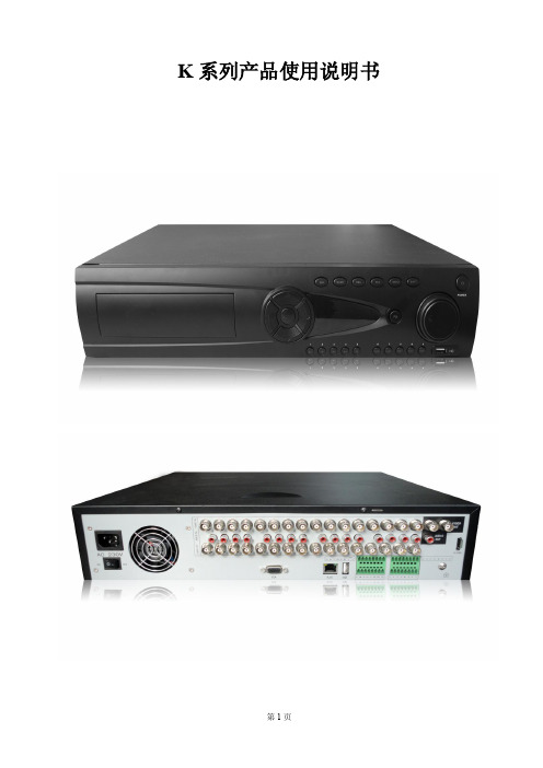
K 系列产品 说明书
第2页
目 录
第一章 产品介绍 .............................................................................................................................................. 5 1.1 产品概述............................................................................................................................................. 5 1.2 产品主要功能 ..................................................................................................................................... 5 第二章 开箱检查和线缆连接 ........................................................................................................................... 7 2.1 开箱检查............................................................................................................................................. 7 2.2 硬盘安装.......................................
扬州爱博德AKD系列电动执行机构使用手册

扬州爱博德自控设备制造有限公司
◆ 高效低噪音 精密蜗轮蜗杆减速机构,间隙小、效率高、噪音低(最高 50 分贝)、寿命长。
◆ 可靠自锁性 蜗轮与蜗杆的自锁性防止了执行机构在断电或断信号的情况下的反转现象。
◆ 离合器自动复位 具有独特的机械式手/自动切换机构,手动操作通过扳动离合器分离手柄后实现,电机一
以继电器触点输出来指示阀门的开关限位及故障报警,另提供如 4~20mA 电流信号输出指 示阀门开度,或者以总线方式反馈当前执行机构各类信息。 ◆ 免开盖调试
各类工作参数设置、开关限位调试均可通过红外设定完成,不需要打开电气罩,使得环境 中的灰尘、潮气等有害物质不能进入执行机构的内部,极大的提高了电气控制部分的可靠性。 ◆ 高智能化
二、产品特点
◆ 液晶显示 采用大屏幕点阵液晶显示,所有菜单均以中文显示,并配以提示说明,界面简单易懂。阀
门的开度大小以数字方式实时显示,并根据工作情况实时显示各类信息;另配以高亮度 LED 发光管指示阀信号、模拟量(4~20mA 电流信号)及各类总线(如 MOBUS、PROFIBUS 等)控制方式,就地操作旋钮可现场调控阀门的位置。 ◆ 状态指示
AKD 系列智能电动执行机构
安 装 调 试 手 册
扬州爱博德自控设备制造有限公司
扬州爱博德自控设备制造有限公司
目录
一、产品概述 .....................................................................................................................................................2 二、产品特点 .....................................................................................................................................................2 三、主要技术指标 .............................................................................................................................................3 四、电动执行机构的操作 .................................................................................................................................4
QBR-400(200)/1140(660)操作手册
周围环境温度为-5℃~+40℃;
周围空气相对湿度不大于95%(&动、颠簸以及与水平面安装倾斜度不超过15°。
第三节
警告!
第一次试运行和测试运行只能由经过良好培训的、有经验的、熟悉井下特殊条件和安全规程的工作组来进行,他们还必须能熟练地操作设备并了解有关操作手册的内容。
图 2 接线腔接线端子
1.4 软起动器出厂时工作电压设置为1140V(对于可以工作在额定电压为AC1140V的软起动器),用户可以根据自己的需要将工作电压调整到660V,只要把电压等级调整快插头接至660V插座即可,同时注意被控电机的电流要小于软起动器铭牌上的额定电流,其它线路不用变动。绝对禁止将额定工作电压为AC660V的软起动器,用于AC1140V上!
1.2本操作手册的适用对象
软起动器的操作人员是本操作手册的适用对象,在工作面内的每一个人都必须阅读本操作手册。
这些人包括:
负责运输人员;
组装/拆卸工;
操作工;
进行工作面日常例行工作;
维护工;
检修工;
指导人员─讲授和/或指导上述工作的。
2.本操作手册的目的
2.1操作手册
本操作手册包含了安全和经济有效地使用软起动器的综合资料,提供了直接或间接操作软起动器的重要指南。因此,要认真地读完这本操作手册,特别注意安全指南,记住安全标志的形状和意义。
电工;
电机及自动化控制系统。
2.维修
通常维修工作由具有这方面特殊知识和技能并符合特殊要求、经过设备检查和维护充分培训的人员来进行。
第二节
软起动器是为矿山工程等含有爆炸性气体或粉尘环境而设计和制造的,只能按照说明书使用软起动器。
旋转雾化器说明书资料
旋转雾化器说明书资料INSTRUCTION MANUAL 指导手册900 SERIES ATOMIZER DRIVE 900系列喷雾器OPERATING MANUAL操作手册ATOMIZING SYSTEM喷雾系统FOR供HEFEI WTE PROJECTCHINA中国合肥垃圾焚烧发电项目CLIENT:用户FISIA BABCOCK ENVIRONMENT GmbH德国费塞亚巴高克环境工程公司D0430INSTRUCTION MANUAL 指导手册900 SERIES ATOMIZER DRIVE 900系列喷雾器TABLE OF CONTENTS 目录Section章节1.0. RECEIVING, STORAGE AND INSTALLATION收货、储存和安装1.1. Receiving and Storage收货和储存1.2. Installation安装1.2.0 General Description概述1.2.1 Atomizer System Control (ASC) 喷雾器控制系统(ASC)1.2.2 Atomizer (Motor) 喷雾器(电机)1.2.3. Variable Frequency Drive (VFD) 变频驱动器(VFD)1.2.4 Permanent Installation设备永久固定2.0. SYSTEM DESCRIPTION 系统说明General喷雾器设计理念–概述 2.1. Atomizer Design Concept -2.2. Atomizer (Motor) - Mechanical喷雾器(电机)- 机械方面2.3. Atomizer (Motor) - Electrical 喷雾器(电机)- 电气方面2.4. Variable Frequency Drive (VFD) 变频驱动器(VFD)2.5. Atomizer System Control (ASC) 喷雾器控制系统(ASC)2.5.0 General Description, Procedure and Sequencing概述、流程和顺序: 2.5.1 Oil Lubrication System润滑系统2.5.2 Oil Return System油回流系统2.5.3 Atomizer Cooling System喷雾器冷却系统2.5.4 Purge Air and Wheel & Shaft Cooling/Wash Water吹扫空气和转盘/轴冷却/清洗水INSTRUCTION MANUAL 指导手册900 SERIES ATOMIZER DRIVE 900系列喷雾器2.6. Theory of Operation of the Atomizer System Control (ASC)喷雾器控制系统(ASC)的操作原理2.6.0 References参考2.6.1 VFD Fault 变频驱动器故障2.6.2 Cooling Water Flow Switch 冷却水流量开关INSTRUCTION MANUAL 指导手册900 SERIES ATOMIZER DRIVE 900系列喷雾器TABLE OF CONTENTS (cont?d) 目录(续)Section (cont?d)章节(续)2.6.3 Lube Oil Level Switches润滑油油位开关2.6.4 Lube Oil Mist Pressure Sensor润滑油雾压力传感器2.6.5 Vibration Element / Transmitter振动元件 / 变送器2.6.6 Upper Bearing RTD Element / Temperature Transmitter顶部轴承热电阻元件/温度变送器2.6.7 Alarm Summary报警概述报警跨接 2.6.8 Alarm Bypass2.7. Summary of the Atomizer?s Utility Services喷雾器的公用设施概述2.7.0 General 概述2.7.1 Instrument Air 仪用空气2.7.2 Lubrication 润滑系统2.7.3 Cooling Water 冷却水2.7.4 Wheel & Shaft Cooling/Wash Water转盘和轴冲洗水3.0. START UP AND OPERATION启动和运行3.1. Commissioning the Atomizer System 喷雾系统调试3.1.0 General / Start-up Engineer 概述/启动工程师3.1.1 Priming the Lubrication System 润滑系统加注3.1.2 Atomizer Preparation and Run-In 喷雾器的准备和试车3.2. Normal Start Up 正常启动3.3. Normal Operation 正常运行3.4. Normal Shutdown 正常停止3.5. Emergency Shutdown of the Atomizer喷雾器的紧急停止INSTRUCTION MANUAL 指导手册900 SERIES ATOMIZER DRIVE 900系列喷雾器TABLE OF CONTENTS (cont?d) 目录(续)Section (cont?d) 章节(续)4.0 ROUTINE MAINTENANCE例行维护4.1. Lubrication 润滑系统4.2. Preventative and Periodic Maintenance of the ASC ASC防护保养和定期维护4.3. Preventative and Periodic Maintenance of the Atomizer and Wheel喷雾器和转盘的防护保养和定期维护4.4. Long Term Storage of the Atomizer 长期存储喷雾器4.5. Instrument Calibration仪表校准5.0 ATOMIZER DISASSEMBLY AND ASSEMBLY INSTRUCTIONS喷雾器拆卸和装配指南5.1 General Recommendations一般建议5.2 Disassembly Instructions 拆卸指南5.3 Re-Assembly Instructions 重新装配指南5.4 Atomizer Wheel Balancing Guidelines 喷雾器转盘平衡调校指南6.0 SPARE PARTS LIST备品备件清单6.1 Recommended Spare Parts - Model 900 Atomizer型号900 旋转喷雾器,建议的备品备件6.2 Recommended Spare Parts - Model EI-804 Wheel型号EI-804喷雾器转盘,建议的备品备件INSTRUCTION MANUAL 指导手册900 SERIES ATOMIZER DRIVE 900系列喷雾器6.3 Recommended Spare Parts – ASCASC面板,建议的备品备件6.4 Recommended Spare Parts – VFD型号A1000,Yaskawa(日本安川电气)喷雾器变频驱动器,建议的备品备件7.0 TROUBLE SHOOTING GUIDE 故障排除指南7.1. General 概述7.2. Operating Log 运行日志7.3. Problem Symptoms and Probable Cause Outline故障症状和可能的原因概述7.4. Specific Atomizer Wheel Troubleshooting Guide喷雾器转盘特殊故障排除指南INSTRUCTION MANUAL 指导手册900 SERIES ATOMIZER DRIVE 900系列喷雾器TABLE OF CONTENTS (cont?d) 目录(续)Section (cont?d) 章节(续)7.5. Other General Inspection and Trouble Shooting Issues其它总体检查和故障排除事项7.6. Freezing Weather Precautions寒冷天气应对措施参考图纸 8.0 REFERENCE DRAWINGS(Please see drawing list at start of section)(请参阅章节前述的图纸清单)9.0 VENDOR DATA 供货商数据(Please see catalogue list at start of section)(请参阅章节前述的目录清单)INSTRUCTION MANUAL 指导手册900 SERIES ATOMIZER DRIVE 900系列喷雾器SAFETY SUMMARY: 安全概述The general information in this part of the summary is for both operating and maintenance personnel. Specific cautions and warnings will be found throughout the manual where they apply, but may not appear in this summary.此部分概述包含的总体信息供操作和维护人员所用。
PEA-C4_HiCoat[0390829]操作手册
![PEA-C4_HiCoat[0390829]操作手册](https://img.taocdn.com/s3/m/8763b772a26925c52cc5bfe9.png)
Operating Manual操作说明书Automatic Powder Spray Gun自动粉末喷枪DANGER危险High Voltage!Turn power off beforeservicing!高压!维修前切断电源!CAUTION当心Read rules for safe op-eration and instructionscarefully!仔细阅读安全操作规则和说明!PEA-C4-HiCoat0390893Powder spray gun PEA-C4-HiCoat Article No. 0390004 PEA-C4高效粉末喷枪部件号 0390004A Fan spray nozzle (Deflector cone)扁喷嘴(导流锥)B Electrode电极针C Outer nut套筒螺母D Spray gun body喷枪枪身E Electrical connection电源插口F Atomizing air connection雾化气口G Powder hose connection粉管接口Z Assembly dimension on the reciprocator 在升降机上的组装尺寸1.) Length for installation dimension Z calculation when utilizing a deflector cone.安装长度Z按使用导流锥时计。
The Corona automatic spray gun can be used for conventional types of powder and metal powder that can be electrostatically charged.电晕星自动喷枪可使用普通类型的粉末和可带静电的金属粉末。
The spray gun is used for industrial powder coating in automatic plants and can be operated with individual control units or with control cabinet modules.本喷枪可用于自动设备中的工业粉末喷涂,并可通过独立的控制模块或者控制柜模块进行控制。
- 1、下载文档前请自行甄别文档内容的完整性,平台不提供额外的编辑、内容补充、找答案等附加服务。
- 2、"仅部分预览"的文档,不可在线预览部分如存在完整性等问题,可反馈申请退款(可完整预览的文档不适用该条件!)。
- 3、如文档侵犯您的权益,请联系客服反馈,我们会尽快为您处理(人工客服工作时间:9:00-18:30)。
接。气动活塞会向上压缩阀闩。
循环
材料使用过程中断。下游的循环阀会打开循环管路。(喷涂)材料会被泵输送
到回路中的 AKD 400 喷枪中。在设备停止时,循环阀始终是打开的。如果不
需要循环,必须控制循环阀关闭循环。
外部控制 供气 供料
控制块循环
SCA-控制系统
旋转传动
图 3 旋转喷枪 AKD400 方框图
中毒。 2.1.4 产品标签
型号设计的例子:
材料 1 的循环回路
材料的编号 M1=材料 1 枪的数量 P2=2 支枪 P3=3 支枪 材料进料口的直径
系列 旋转胶枪 ADK 400 =真空,滴流,平片流和喷流
在每个旋转胶枪 AKD 400 上都有一个标注 SCA Schucker 零件编号的铭牌。
2.3 技术标准(规格) 旋转喷枪 AKD400 的特征
3.2 结构
图 2 旋转喷枪 AKD400 A 机器人安装法兰 B 力矩支架 C 旋转传动导入外壳(空气) D 旋转传动导入外壳(材料) E轴
F 喷嘴头 G 气动驱动装置外壳,阀门
H 循环阀(可加热的)
3.3 控制/功能
总述
SCA 控制系统可以通过 5 位 2 通阀开启喷枪上的各个针阀。针阀转换供给喷嘴
取决于实际情况。 循环阀(13)
气动控制材料的供应。 在正常的作业中,AKD400 旋转喷枪是通过定量仪(缸)持续供料的。一旦停止供料, 循环阀会打开,回路中的材料会被泵打入,以避免材料固化和沉积。 循环阀有单动和双动模式。循环阀是通过(输送)材料的压力打开的。在双动模式中, 循环阀是通过气动增压打开的。循环阀(无论是单动还是双动)都是气动关闭的。 循环阀可以被加热(14),可以保证材料所需的稠度。
故障
原因
可能的原因
对策
SCA 控制系统没有运 打开控制系统 行?
阀头没有开启
喷嘴堵塞 检查压缩空气供给
清洗喷嘴,如有必要, 更换喷嘴 连接压缩空气供给
彻底清洗阀闩和导
阀闩磨损?
套。如果有必要的话,
没有材料涂布
更换阀闩。 定量仪(缸)是否充 等待定量仪(缸)充
满?
满
检查桶式泵的气动供 将气动供给连接到桶
宽度
(mm)
161 根据要求
高度
(mm)
150 根据要求
空间要求
(mm)
根据要求
重量
(kg)
根据要求
扭矩
根据要求
喷嘴角度
0°,90°
0°,45°,90°
连接件
压缩空气供给
G1/8”(DIN8473 等级 4-5;
G1/8”(DIN8473 等级 4-5;
4.5-8bar)
4.5-8bar)
最低气动压力
作业区域
3.4 部件和组件描述 法兰(1)
通过一个接头(配件)将喷枪 AKD400 连接到机器人的第六轴上。机械臂的旋 转带动 力矩支架 牢固地安装到机器人的第五轴上。在机 器人第六轴旋转时,确保喷枪的旋转传 动导入不发生转动从而保护供给管路不 被损坏。(在图中不可见) 气动驱动 驱动枪中的气动活塞(4)。2 个或者 3 个气动阀(5)的每个阀控制一个气动 活塞。 旋转传动导入 主要包括法兰(1),气动(驱动)外壳 (6)和物料部分外壳(7)和双套轴 (2)。旋转传动导入通过导轨,滑块 和 O-形圈构成的结构密封。 NAD 枪(8)
气动驱动有泄漏点 材料部件有泄漏点 压缩空气泄露
可能的原因 系统中混入空气 针阀阻塞 材料问题 材料变硬和污染
喷枪阀门处有压缩空 气泄露
对策 冲洗系统 清理针阀 检查粘结剂批次 清洗或更换过滤器 清洗法兰,更换密封 件,更换压缩弹簧 更换针阀密封件 更换材料部件密封件 更换气动外壳里和喷 枪上的密封件
·更详细的信息请参考“保养”章节
9.2 清理 为了保证使用寿命和可靠性,SCA 组件和整个材料喷涂系统需要定期保养。
·在保养工作前或保养工作中清理旋转喷枪 AKD 400
·注意,清洗药剂的选择取决于(输送)材料的种类。保证清洗药剂不会对 对组件造成损坏。
·如了解更多信息,请联系材料制造商。
·禁止用水或者其他液体清洗电子组件! ·保证水或者其他液体不渗入到电子组件中!
(bar)
5
5
最高气动压力
(bar)
8
8
喷嘴入口
G1/4”
喷嘴出口
根据使用确定喷嘴
循环回路出口
G1/4”
G1/4”
排放物
AKD 400 旋转喷枪内部没有超过法定标准的内部排放物。
更精确的名称/版本在部件列表中。
3 结构与功能 3.1 总述 旋转喷枪 AKD 400 用于定量输送膏状物,如粘接剂、绝缘或密封材料。可转动轴承上的喷嘴 头和多种喷嘴头的使用甚至可以保证材料喷涂到难以作业的区域。 可以通过一个联结器和力矩支架旋转喷枪 AKD 400 牢固地安装到机器人的第六轴上。在使用 过程中,机器人的第六轴旋转喷嘴头。在喷涂过程中,喷嘴头可以使用多个喷嘴在不同的角 度喷涂。喷嘴决定了材料的涂布使用取决于实际情况。 SCA 控制系统通过与喷嘴阀门连接的 5 位 2 通(5/2-way)阀来控制其开关。喷嘴阀门控制 (喷涂)材料在喷嘴处通过。机器人指定了材料涂布时的轨迹和路线以及喷嘴头的旋转。 旋转喷枪 AKD 400 主要包含以下几个部分: ·具有 2 到 3 个气动阀以及空气入口板的气动驱动(装置)。 ·具有法兰,外壳和分轴的导入旋转传动导入。 ·包含 2 到 3 个双向活塞,2 个喷嘴阀及其具有分配器和 2 个喷嘴(0°,90°)或 3 个喷嘴 (0°,45°,90°)的喷嘴头的喷枪 ·一个循环阀 (喷涂)材料通过循环阀从定量器进入旋转导孔。 (喷涂)材料通过机器人驱动的分轴进入到双嘴喷枪。每个喷嘴的气动阀控制阀针的上下运 用。 如果(喷涂)材料的使用过程被中止,(系统)会停止材料输送并且会打开循环阀。 (喷涂)材料在旋转喷枪 AKD 400 中循环。 在正常使用中,(系统)会打开材料输送并关闭循环阀。 一旦材料发生持续性的变化,可以避免材料在使用过程中的混合变化。
电阻以确定加热棒和温度传感器是否失效: 温度传感器: 3 号插针和 4 号插针之间的电阻是 109Ω (+/-1Ω )
通过圆柱销的上部轴(top shaft)连接。 包含了两个气动控制的双向活塞,用于开闭针 阀(9)。
弹簧(10)不能作用于双向气动驱动的 物料压力。
如果停止供应压缩空气,弹簧会使针阀处 于关闭状态。
图 4 旋转喷枪 AKD 400 的剖视图
喷嘴头(11) 有两个喷嘴(12),材料可以通过喷嘴以不同的角度喷涂。喷嘴决定了材料的涂布使用
·如果您确认所有的部件都处于干燥状态,您可以重新启动 SCA 组件和整
个
个材料喷涂系统。
9.3 保养
9.3.1 工具/资源需求
您需要以下工具和辅助材料/资源对旋转喷枪 AKD 400 进行保养。
名称
使用部位
· 各种螺丝刀
· 擦拭布
清洗组件
· 清洗药剂(例如,塑化剂)
清洗组件
· 无硅酮和无酸油脂
润滑组件、密封件
· 气动油脂
润滑气动密封件
· 组合钳
安装旋转传动导入中的滑环
· 螺纹紧固件拔出器
拆除枪上的密封套
· 定型芯棒
更换或者修复密封件
· 镰刀型扳手
安装套筒螺母
9.3.2 目视检查泄露 在运行过程中,持续的摩擦会导致密封环、转接环和导向环磨损,进而造成泄露。当对
旋转喷枪 AKD 400 和循环阀进行保养工作时,尤其要检查密封环、转接环和导向环。由于 磨损取决于材料的特性,无需对密封环、转接环和导向环之间的间距进行详细说明。 当发生以下情况时,您必须更换密封环、转接环和导向环: · 材料从外壳泄露出来。 · 空气从气动驱动装置中泄露出来。
的材料。机器人指定了材料应用时的轨迹和路线以及喷嘴头的旋转。
循环阀室被分开控制的。如果控制系统注册了一个中止程序,材料会被泵输送
到回路中。
喷枪关闭 物料使用过程没有被释放。5 位 2 通阀会将压缩空气释放到被控制的针阀的顶
部连接。气动活塞会向下压缩阀闩。
喷枪打开 物料使用过程被释放。5 位 2 通阀会将压缩空气释放到被控制的针阀的底部连
材料软管泄露
更换软管
材料供应不足
关闭循环阀
循环阀开启
检查压缩空气供给
检查控制信号
循环阀磨损
清洗循环阀,如有必 要,更换循环阀
材料从喷枪阀门溢出 材料泄露到非要求区
更换喷枪和针阀密封 件
域
更换旋转传动导入部
材料从旋转传动导入部分溢出
分密封件
故障 材料流出(滴落)
原因 针阀没有完全关闭
空气从针阀泄露 材料从材料部件泄露 噪音大(危害)
2 技术描述 2.1 产品描述 2.1.1 全貌图
图 1 旋转喷枪 AKD 400 P2 和 P3 2.1.2 设计用途
旋转喷枪 AKD 400 只可能用于定量输送膏状物,如粘接剂、绝缘或密封材料。 SCA 组件可能无法用于其他材料或化学品。 如果非正常使用 SCA 组件,可能会导致螺旋接头、支架和系统部件爆裂,并且/或者支 架/固定螺丝被扯掉。
说明手册(技术手册) 旋转喷枪 AKD 400
(根据英文版翻译,仅供参考)
目录 认证 有效页面清单 补充文件 技术说明书 标准和参考 总体安全信息 目录 图表 关于操作说明的目录 质保保修 制造商担保 1. 安全 1.1 安全信息:警告,小心,危害种类 1.2 拥有和使用者需注意的职责 1.3 个人注意的职责 1.4 预期用途 1.5 非预期用途 1.6 安全操作 1.7 气动风险 1.8 机械风险 1.9 温度风险 1.10 动火风险 1.11 电力风险 1.12 非预期故障造成的风险 1.13 输送材料和其他维护过程造成的风险 1.14 其他风险 1.15 环境保护 2. 技术描述 2.1 产品描述 2.2 技术标准(规格) 3.结构和功能 3.1 总述 3.2 结构 3.3 控制/功能 3.4 部件和组件描述 4.运输 4.1 安全描述 4.2 供货范围 4.3 送货 5.组装/安装 5.1 总述 5.2 安装位置 5.3 连接
