如何使用分光器
分光器安装规范

盒式1:16分光器 (左边SC、右边
FC)
托盘式1:32 分光器(FC)
安装规范
1、安装位置:
• 固定在卡槽内(若箱体
内卡槽,可使用双面胶、
魔术贴等进行固定)
2、安装原则:
固定在卡槽内部
• 平稳美观
• 方便跳纤及维护
平稳美观
案例分析
问题: 完成一个分光器的二级扩容,需要提供哪些图片给容量组?
2、挂牌地址 地址需与现场相符,如挂牌错误,请在图片 备注:现场地址无误,光缆牌错误
案例解析2
3、旧分光器标签与使用情况
4、第三芯或者第四芯 5、一级分光
现场每一个旧分光器都要拍下照片 扩容另加一张箱子图 器主纤照片
如果是第三芯或者第
四芯扩容另加一张箱
子图
6、一级分光器使用情况(标签与
所用端口)
测试
参考答案: • 二级分光器标签+二级分光器收光图 • 挂牌地址 • 旧分光器标签与使用情况 • 第三芯或者第四芯扩容另加一张箱子图 • 一级分光器主纤照片 • 一级分光器使用情况(标签与所用端口)
案例解析1
1、二级分光器标签+二级分光器收光图 新扩容的二级分光器标签+二级分光器收 光图(非二级分光器主纤收光),标签照 要能看清楚,要能看到分光器
题目
1、判断题:FTTH一级模式的一级分光器收光不 低于-1dbm。 答案:(错)FTTH一级模式的一级分光器收光不 低于-2dbm
2、选择题:上联信息包括哪些内容(多选题):
A、 OLT板口
B、分光器名
C、本端分光器名称 D、上联分光器端口号
答案:(ABD)上联信息包括:OLT板口+分光器
如何使用分光器范文
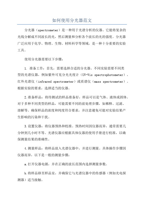
如何使用分光器范文分光器(spectrometer)是一种用于光谱分析的仪器。
它能将复杂的光线分解成不同波长的光,然后测量和分析各个波长的光的强度。
分光器广泛应用于化学、物理、生物、材料科学等领域,是一种十分重要的实验工具。
使用分光器需要以下步骤:1. 准备工作:首先,需要选择合适的分光器。
不同实验需要不同类型的光谱仪器,例如紫外可见分光光度计(UV-Vis spectrophotometer)、红外光谱仪(infrared spectrometer)或质谱仪(mass spectrometer)。
根据实验的要求,选择适当的仪器。
2.准备样品:将待测试的样品准备好,样品可以是气体、液体或固体。
对于多种不同类型的样品,可能需要不同的前处理步骤,如稀释、过滤、溶解等。
确保样品的浓度和纯度符合要求,并注意避免可能对实验结果产生影响的污染和干扰。
3.设置仪器:将仪器预热和校准。
预热时间因仪器而异,通常需要几分钟到几小时不等。
光谱仪器应根据具体仪器的使用手册进行校准,以确保测量结果的准确性。
4.测量样品:将样品放入光谱仪器中,并进行测量。
具体操作步骤因仪器而异,以下是一般的测量步骤:a.打开仪器电源,并在正确的波长范围内选择测量参数。
b.将样品移至样品室,并确保它与光谱仪器中的传感器(例如光电探测器)适当接触。
c.设置所需的光谱扫描范围和积分时间,并选择适当的测量模式,如吸光度或发射光谱。
d.开始测量,并观察光强度随波长变化的曲线。
根据需要可以保存数据。
5.数据分析:根据测量的数据进行分析。
具体的分析方法因实验目的而异,可以利用软件对数据进行处理和解释。
常见的分析包括浓度测定、光谱峰分析、傅里叶变换等。
6.清理和维护:使用完仪器后,应将光谱仪器关机。
根据仪器制造商的指南,清洁仪器表面和样品室以去除可能的污垢。
定期维护仪器以确保其正常工作,并按照制造商的建议更换灯源和其他耗材。
需要注意的是,使用分光器时要遵循实验的操作规程,并按照安全操作要求进行实验。
分光器的连接方法

分光器的连接方法分光器是一种光学器件,主要用于将进入分光器的光信号按照一定的比例进行分离和合并。
分光器的连接方法包括二分光、三分光和N分光,下面将分别介绍这三种连接方法。
一、二分光连接方法二分光连接方法是最简单的连接方式,主要用于将进入分光器的光信号分成两路。
具体连接方法如下:1. 将需要分光的光源连接到分光器的输入端口;2. 将两根光纤连接到分光器的两个输出端口,并将另一端连接到接收设备或其他光纤器件;3. 如果需要将光信号合并在一起,可以在分光器的两个输出端口之间添加一个耦合器,并将合并后的光信号发送到接收设备或其他光纤器件。
二、三分光连接方法三分光连接方法是将进入分光器的光信号分成三路。
具体连接方法如下:1. 将需要分光的光源连接到分光器的输入端口;2. 将三根光纤连接到分光器的三个输出端口,并将另一端连接到接收设备或其他光纤器件;3. 如果需要将光信号合并在一起,可以在分光器的三个输出端口之间添加一个耦合器,并将合并后的光信号发送到接收设备或其他光纤器件。
三、N分光连接方法N分光连接方法是将进入分光器的光信号分成多路(N路)。
具体连接方法如下:1. 将需要分光的光源连接到分光器的输入端口;2. 将N根光纤连接到分光器的N个输出端口,并将另一端连接到接收设备或其他光纤器件;3. 如果需要将光信号合并在一起,可以在分光器的N个输出端口之间添加一个耦合器,并将合并后的光信号发送到接收设备或其他光纤器件。
需要注意的是,在连接分光器时,应尽量避免光信号的反射和散射,以免影响信号的质量和传输距离。
为了保证连接的稳定性和可靠性,还可以采用光纤连接盒、光纤衰减器、光纤保护套管等辅助器件。
此外,分光器连接方法还包括插入损耗的处理。
插入损耗是指在分光器操作过程中,由于光的分离和合并导致的信号强度衰减。
为了减小插入损耗,可以选择低损耗的分光器和合适的连接方法,同时还可以调整输入光信号的功率和波长,以达到最佳的性能和传输效果。
分光器的用法

分光器的用法分光器的奇幻旅程:探索科学世界中的“色彩魔术师”在科技的奇妙宇宙中,有一种设备犹如哈利·波特的魔法棒,能将看似单一的光线分解成一道道斑斓的彩虹——它就是我们今天的主角——分光器。
这个名副其实的“色彩魔术师”,凭借其神秘莫测的工作原理和广泛的应用领域,让我们一起踏上这场揭秘之旅,领略其独特的魅力。
首先,咱们得从分光器的基本原理说起。
这玩意儿可不简单,它的核心能力在于能把复合光“掰开揉碎”,通过折射、反射或者衍射等手段,把一束混合光拆分成各种不同波长的单色光,就像一位精细的手艺人,耐心地解开缠绕在一起的彩色丝线。
这种“分光”的过程,堪称是物理学舞台上的一场绚丽舞蹈,让人拍案叫绝!你可能会问:“嘿,分光器这‘光影解码器’究竟有何神通?”这话问得好!在科研实验室里,分光器可是个不可或缺的大忙人。
化学家借助它分析物质结构,通过检测物质对特定波长光的吸收情况,像侦探一样揭示出化合物的秘密身份;天文学家则用它研究遥远星体的组成,让那些隐藏在星辰大海背后的元素无处遁形;生物学家更是利用荧光分光光度计,精确测量细胞内分子的活性,仿佛手中握着生命密码的钥匙……而在日常生活中,分光器也悄然发挥着作用。
比如光纤通信系统中的分光器,如同信息高速公路上的智能分拣员,将传输的光信号按需分配到不同的通道,实现高效的信息传输与交换;又如我们常见的舞台灯光设备,其中就包含了光学分光器的身影,它们巧妙地将白光切割重组,为观众呈现出五彩斑斓的视觉盛宴。
所以,每当看到那繁星点点的夜空,或是在音乐会现场感受流光溢彩的舞台效果时,不妨想象一下背后默默工作的分光器,正是这位“色彩魔术师”施展魔力,为我们揭示了光的奥秘,赋予世界无限可能。
这就是分光器的魅力所在,它不仅是一个工具,更是一种思维方式,引领我们在探索未知的道路上勇往直前,不断挖掘光与色彩背后蕴藏的科学宝藏。
如此这般,分光器在人类智慧的舞台上大放异彩,以独特的姿态诠释了科技的力量与美,而我们的生活也因此变得更为丰富多彩,充满惊奇与想象。
分光器使用说明(2)

图 6 倾斜插入/错误
图 7 垂直插入/正确
然后将输入端和每个输出端依次接入测试系统后判定光学指标是否符合要求。如果是其 它型号的连接器根据实际型号均需要确定安装到位。
光纤分路产品使用说明书(2011 版)
上海乐通通信设备有限公司
三、常见问题的处理:
输出端的某个通道或者所有通道指标异常。这是最为常见的问题,通常情况下,分路器 部分不良的可能性比较小,主要集中在连接器部分,而连接器又主要集中在光纤端面上,生 产现场一般的处理方法有:
洁时应将蘸有酒精的擦拭纸(至少 3 层以上)平铺在桌面上,擦拭时应沿着陶瓷面的角 度向一个方向擦拭,不应来回擦拭,以防止损坏端面。
d、清洁完成后,区分输入和输出端口,然后将待用产品的防尘装置去掉,把连接器装 配上。安装时需注意(以 SC 型为例)如下情况:
安装连接器应使连接器的键的面和适配器缺口面一致,然后沿着适配器水平的插入。 当听到“咔咔”的声响时,再观察连接器上的白线是否和适配器边线平齐,如平齐表示 卡锁到位。
(2)光纤分路器产品常见的封装形式:
1. 模块式封装
FBT 型和 PLC 型分路器通常的模块封装形式有:
型号
规格
1(2)×2
FBT 分路器
1(2)×2~6
1(2)×7~32
1(2)×4
1(2)×8
PLC 分路器
1(2)×16
1(2)×32 1(2)×64
封装尺寸(mm) 100×19×9 100×80×9
图 22 LC 型适配器
图 23 MU 型适配器
回波损耗(dB) (输出端截
止) ≥50
回波损耗(dB) (输出端开
路) ≥18
≥50
≥20
分光光度计使用注意事项讲解

分光光度计的使用一.使用及维护1.安装环境1.1温度要求:装在不受阳光直接曝晒的房间;最好装空调,使室温维持在(20±2℃);仪器附近不应有高温的暖气管或其它电热器具;仪器后面板与墙之间应留一定空间。
1.2湿度要求:水蒸气在(1 350~1 450)nm和(1 800~1 950)nm两个波长区域内有光吸收,会严重干扰测定。
潮湿会导致分光器反射膜层斑剥、脱落等。
故相对湿度最好保持在(40~75)%。
高档紫外-可见-近红外分光光度计要用高纯氮气冲洗。
干燥筒内的变色硅胶应及时更换。
1.3防震、防尘、防腐和防电磁干扰:2.光源灯2.1拿灯时不要碰窗口,以免手上的油污经紫外照射后,形成结痕难以去掉.倘若不小心而碰触,应及时用无水乙醇抹擦干净。
2.2 灯有寿命,要节约使用.但工作间歇时间短,不要关灯和停机.2.3 在灯虽然能点亮,但不稳定或强度大大减弱而影响测量时,就应更换新灯.2.4应待灯冷却后,再重新启动.启动后预热15-30min才能读数.2.5不要用眼睛直视灯,因为紫外辐射会损伤人的眼睛。
3. 单色器3.1单色器是仪器的心脏部分.不要轻易装、拆,也不要去摸触镜面.3.2 平时要保持内部干燥,及时更换干燥剂,以防止色散元件和反射镜受潮而发霉,测定挥发样品必须使用密封吸收池,以免样品蒸气进入单色器,腐蚀反射镜、透镜及色散元件的镜面.3.3 如果选定波长和狭缝宽度是用旋钮,则要按说明书规定的方向转动到欲测的位置,切勿来回转动,以防回衡误差.4. 样品室4.1 样品室是存放吸收池的地方,防止样品的交叉污染,决不可将样品留在样品室中过夜.4.2 吸收池的光学面一定要维护好,不能用刷子刷.否则光学面发毛会增加散射而影响测定准确度.保护吸收池最重要的一条是使用后及时清洗,否则留下液痕,日后再洗,事倍功半.用完的吸收池可放在中性肥皂水中(将十二烷基硫酸钠用蒸馏水配制成透明的稀溶液),或放在8 mol/l盐酸加45%乙醇的等量混合液中浸泡,然后用自来水冲洗,再用蒸馏水洗净,放在无灰尘的地方凉干备用.如果急于使用,可在真空中抽干.但不要用热吹风吹干。
如何使用分光器

如何连接分光器1常见问题在部署探针及分光器时,常见的问题有二个:极性问题和光功率问题。
1.1 极性下图示例说明了分光器与DTE、DCE网络设备的连接原理。
分光器只能对TX信号进行正确地分光,本图说明了采用正确的极性进行连接。
DCE Tx(DTE Rx)数据连接到探针采用蓝色标记,DTE Tx(DCE Rx)数据连接到探针的采用红色标记。
如果光缆在双向都接反了(即混合极性,mixed-polarity),用户原有的链路还可正常工作(DTE-Tx to DCE-Rx and DTE-Tx to DCE-Rx),但是分光器有时不能正常工作,探针可能接收到较低光功率的光信号或接收不到光信号(低于探针的光功率范围)。
一个不影响原有链路正常工作并检测混合极性的方法是测量分光器输出到探针的光功率。
若光功率非常低,多达-30db to -40db,就有可能是采用混合极性的连接方法。
若已经确认是混合极性问题,或想确认是否采用了混合极性接法,可采用以下方法:[警告-此操作可能导致链路的中断]1 –同时颠倒分光器A、B端口的连接,可能发生如下结果:A: 探针接受到光功率增强,探针可以监控到数据[这表时原来是混全极性连接,现在是正确的连接方式]或者B: 探针接受到的光功率更弱了(现在是错误的混合极性连接)恢复原来的连接方式并检查光缆的衰减,是否光接头有污或损坏的光缆。
2 –测量连接分光器的每根光缆和二根光缆的光功率:A: 断开连接分光器的所有光缆并记录下连接的方式.B: Take a light reading off of the Network “A” cable, then plug it into the tap in the same orientation as it was before and get the readings off the probe connections. [One will be "0" the other will have a value]C: Now disconnect Network “A” , and repeat the above procedure with the cable from Network “B” - again you will get a valid reading and a "0".D: Now connect BOTH cables and take a reading off of the probe-connectorsIf the light level at the probe connectors is about the same as it was in A: and B: then you are connected correctly. If, however, you see a much greater difference (-15db or more) at the probe connectors when both cables are connected than with either side alone, then you have a mixed-polarity connection and should reverse the cables.These polarity issues will not come up if you are using cables with polarized connectors at both ends of the cable.1.2 光功率2Netscout Probes的光学参数NetScout makes a line of Fiber Optics probes for most mainstream circuits. The following tables reflect the light sensitivity of our different probes.It should be noted that, as stated previously, there is a difference between the …typical‟ light level ranges that are found usable in a test laboratory environment and that of a production network where any downtime and/or failure are not acceptable. We therefore differentiate between the absolute range of light figures supplied from the vendors under which the optical receivers on the NICs are known to function, as opposed to the range of light under which we are confident of 100% performance and reliability. We list the minimum values for each probe, both the typical value and our own recommended value from field and customer experience.It is this latter range that we strongly suggest be used and that readings on the …edge‟ of this suggested range be considered marginal. For example, we would consider a light reading for the 9100 model ATM OC3/OC12 probe of -26dBm to be a marginal level and would suggest raising it to –25dBm or better to insure reliable operation of the probe. Even though the manufacturer of the NIC receiver would suggest –30dBm is appropriate, we have found quite often that field experience does not bear this out when not in a lab. A 1dBM rise will equate to a 22% increase in light.2.1 Netscout OC3 and OC12 ATM Probes:Maximum light level NetScout Probe Model Typical Minimum range / Fieldvalue suggested8110 Multimode -30 to –31dBm / -26dBm -14dBm8110 Singlemode ** -30 to –31dBm / -26dBm -14dBm9110 Multimode -26 to –30dBm / -26dBm -14dBm9110 Singlemode -28 to –31.5dBm / -26dBm -8dBm-20dBm / -17dBm +4dBmGigabit (8900 and 9900series)Fast Ethernet (8213, 8243) -30dBm / -28dBm -10dBm**Note: The 8110 Single-mode Probe uses a special Tap-to-Probe cable thatadds an additional 1dBm of signal loss.2.2 NetScout POS ProbesThe POS OC3/OC12 probes use the same receiver chip-sets as the ATM OC3/OC12 probes so they have the same light sensitivity2.3 NetScout Gigabit Probes:2.4 NetScout Fast Ethernet Probes:。
分光器的用法

分光器的用法分光器是一种用于将进入的光束按照波长进行分离的仪器,其主要用途是分析物质的成分和性质。
分光器在化学分析、生物技术、环境监测等领域都有广泛的应用。
本文将详细介绍分光器的原理和用法,希望能够帮助读者更好地了解和应用这一仪器。
一、分光器的原理分光器的基本原理是利用光的色散性质,将不同波长的光线分离开来。
常见的分光器包括衍射光栅分光器、棱镜分光器和光纤分光器等。
这些不同类型的分光器都能够实现将复杂的光谱分解成单一波长的光束,从而方便后续的光谱分析和应用。
二、分光器的用法1. 样品的制备在进行分光器的光谱分析之前,首先需要对待测物样进行制备。
制备样品的方法会因应用而有所不同,但一般来说,需要将样品处理成可进行光谱分析的形式,比如溶解、固体研磨、稀释等。
对于不同类型的分光器,需要根据其特性来制备样品,以保证后续的分析准确可靠。
2. 选择合适的分光器和光源根据具体的分析需求,选择适合的分光器和光源。
对于紫外可见分光光度计,一般采用近、可见光源,而对于红外分光光度计,则需要红外光源。
还需要根据分析样品的波长范围和所需分辨率来选择合适的分光器。
3. 调试和校准在进行实际的光谱分析之前,需要对分光器进行调试和校准。
这包括调节光源强度、选择合适的光阑尺寸、调节检测器的灵敏度等。
还需要进行波长标定,以保证分光器的准确性和稳定性。
4. 进行光谱测量当分光器调试和校准完成后,就可以进行样品的光谱测量了。
在进行测量时,需要根据具体的分析方法和需求,选择合适的手段和参数设置。
比如选择合适的检测波长、设置光谱扫描范围、调节光谱积分时间等。
5. 数据处理与分析在完成光谱测量之后,还需要对得到的光谱数据进行处理和分析。
这包括数据的平滑处理、背景校正、峰识别、峰面积计算等。
通过对光谱数据的处理与分析,可以获得样品的光谱特征信息,帮助进一步分析样品的成分和性质。
6. 结果解读与应用根据光谱分析的结果,进行解读和应用。
根据不同的需求,可以对样品的成分、浓度、结构等进行进一步的分析和评价,为具体的应用提供支持。
分光器原理

分光器原理分光器是一种常见的光学仪器,它可以将入射的光线按照不同的波长分离出来,是光谱仪、激光器、光通信等领域中不可或缺的重要组成部分。
那么,分光器是如何实现光线的分离的呢?接下来,我们将从分光器的原理入手,来详细介绍分光器的工作原理。
首先,我们来看一下分光器的基本结构。
分光器通常由入射光口、出射光口、光栅和反射镜等部分组成。
当光线从入射光口进入分光器时,首先经过光栅的作用,光栅会根据光线的波长将其分成不同的色散光。
然后,这些不同波长的光线被反射镜反射到不同的出射光口,最终实现了光线的分离。
其次,我们来了解一下分光器的工作原理。
分光器的工作原理主要依赖于光栅的色散效应。
光栅是一种具有周期性结构的光学元件,当入射光线通过光栅时,不同波长的光线会根据其波长的不同被分散成不同的角度。
这就是光栅的色散效应。
而反射镜的作用则是将这些不同角度的光线反射到不同的出射光口上,从而实现光线的分离。
再次,我们来分析一下分光器的应用。
分光器广泛应用于光谱仪、激光器、光通信等领域。
在光谱仪中,分光器可以将入射光线分离成不同的波长,从而实现对光谱的分析和测量;在激光器中,分光器可以实现对激光光谱的调谐和分析;在光通信中,分光器可以实现多路复用和波分复用等功能。
可见,分光器在光学领域中具有非常重要的应用价值。
最后,我们来总结一下分光器的原理。
分光器利用光栅的色散效应和反射镜的反射作用,实现了对入射光线的分离。
它在光学仪器中具有广泛的应用,为光谱分析、激光调谐、光通信等领域提供了重要的技术支持。
综上所述,分光器是一种利用光栅的色散效应和反射镜的反射作用实现光线分离的光学仪器,具有广泛的应用价值。
通过对分光器原理的深入了解,我们可以更好地理解分光器在光学领域中的重要作用,为相关领域的研究和应用提供技术支持。
1分2光纤分路器的用法

1分2光纤分路器的用法随着科技的不断进步,人们对于网络的需求也越来越高。
而光纤网络作为一种广泛应用的网络形式,其稳定性和传输速度都远超过了传统的有线网络。
但是,对于一些需要连接多个设备的场合,单一的光纤连接往往无法满足需求。
这时,1分2光纤分路器就成了一种必要的设备。
1分2光纤分路器,顾名思义,就是将一个光纤信号分成两个信号输出,供两个设备使用。
其实现的方式是通过光电转换,将光信号转换为电信号进行处理,然后再将电信号转换为光信号输出。
这样,就可以实现光纤信号的分流,使得多个设备可以同时接入光纤网络。
使用1分2光纤分路器的好处是显而易见的。
首先,它可以节省成本。
相对于为每个设备都单独提供一根光纤线,使用分路器只需要一根光纤线就能实现多个设备的连接,不仅减少了线路的数量,也降低了成本。
其次,它可以提高效率。
由于分路器可以同时将信号分流给多个设备,因此多个设备可以同时进行数据传输,大大提高了网络的传输效率。
此外,使用分路器还可以提高网络的可靠性。
因为多个设备可以同时接入网络,一旦某个设备出现故障,其他设备仍然可以继续使用网络,不会影响整个网络的运行。
当然,使用1分2光纤分路器也有一些需要注意的问题。
首先,由于信号被分流,每个设备接收到的信号强度会减弱,因此需要注意信号的衰减问题。
其次,在使用分路器时,需要保证分路器的质量和性能,确保其能够稳定地将信号分流给多个设备。
最后,需要注意分路器和设备之间的匹配问题,确保它们之间的接口类型和速率相匹配,避免出现不兼容的情况。
总之,1分2光纤分路器是一种非常实用的网络设备,它可以为多个设备提供高速稳定的光纤网络连接,同时也能够节省成本、提高效率和可靠性。
在使用时需要注意一些问题,但只要正确使用,就能够发挥其最大的作用,为我们的网络生活带来更多的便利和效益。
分光器挂测操作手册

分光器挂测操作手册
1、从综合资管发起分光器挂测
综合资管和挂测系统已开通挂测实时发起接口,可在综合资管直接发起挂测。
在分光器查询界面查询出需要挂测的分光器,勾选后点击“发起分光器挂测”,如下图所示:
2、挂测发起成功提示及错误信息说明
2.1数据插入成功:该提示说明数据已成功发送至挂测系统,可在挂测系统进行挂测工
单的发起和处理。
2.2此分光器ID存在未挂测或挂测中的定单:该提示说明此分光器已通过视图批量同步
方式同步到挂测系统中,可在挂测系统中直接进行工单处理。
2.3分光器的挂测状态为“通过”或“挂测中”,不允许发起挂测:如果分光器挂测状态已
经为通过,则不能再发起挂测。
如果状态为挂测中,则说明已经通过按钮发起过挂测,需要再挂测系统中进行工单处理和回复,只有在回复挂测未通过后才能重新发起挂测。
2.4设备找不到PON口:要发起分光器挂测必须要完整录入上联到OLT端口的完整光路
及关联的VLAN,否则不能发起挂测。
PON系统分光器的规划和使用

PON系统分光器的规划与使用一、分光器的选择由PON系统的链路设计决定抛开EPON与GPON之争,PON网络中目前的技术已经可以实现1×128的光分路比,这为PON的ODN设计带来非常大的灵活性。
因此在光链路设计时,如何根据OLT PON的发射及接收光功率预算来进行链路规划很重要,一般是将整个系统中需要布置的ONU进行区域划分,以此来确定PON的覆盖范围。
实际环境下,ONU的区域划分要根据地理位置(道路、桥梁、山坡、河流、管道、建筑楼层等等因素)来确定,图1是一个典型的二级分光示意图,通常的使用方法是一级采用1×4,则二级采用1×8,或一级采用1×8,二级采用1×4,可是实际环境各异,常常出现二级分歧富裕或不够,例如二级分光1×8时,刚好这个区块有9栋楼,从别的区块单独放一条光纤过来不实际,而增加一个分光器对PON来说又太浪费,因此光链路的规划是非常的重要,分光器如何设置必须在光链路设计时确定。
图1 二级分光示意图二、分光级联的确定这个问题对于不同的运营商有不同的想法,对于广电来说,为了与其HFC 网络匹配,理想的方法是采用不均分分光器(例如5%:95% 1×2分光器),在光功率预算许可的情况下,通过多级级联达到覆盖大范围几千用户的目的,如图2。
图2 多级分光示意图这种方法在理论上可行,实际在北美也有应用,但是更多的级联带来维护和管理的困难,首先光纤链路上有很多的分歧点(最多可能32或64或128),这些点除了分光器及熔接点的插入损耗以外,还会因多重反射增加系统噪声,致命的问题来自于前端分光器故障将导致后端大面积的业务中断。
还有一个大问题是最远端ONU与最近端ONU由于距离OLT的距离差很大,因PON的TDMA 机理,必须增大系统的插入时延以达到OLT在逻辑上与各个ONU等距离的目的,系统的效率将受到较大的影响。
在我国PON的实际部署中,这种级联方式很少使用。
分光器的使用方法

如何正确使用分光器?
分光器是一种用于分离光线的仪器,广泛应用于光学研究和生产制造中。
那么,如何正确使用分光器呢?下面,我们来介绍一下具体操作步骤:
1.准备工作:将分光器稳定地放置,保持水平,调直支撑脚,使其不发生晃动,然后将光源接通。
2.制备样品:将需要测量的样品制备好,放置在样品台上。
3.调整入射角:通过转动分光器的旋钮,调整入射角度,使光线正常射入样品。
4.进行测量:开启探测器,记录下样品的各项数据,如透射率、反射率等。
5.计算结果:根据收集到的数据,进行计算,得出样品的相关数据。
6.清洁仪器:使用完毕后,记得对仪器进行清洁,避免污染和损坏。
以上就是分光器的使用方法。
在使用时,还需要注意以下几点:
1.尽量减小测量误差,保持仪器和样品的稳定状态。
2.避免任何外力干扰,以确保精度。
3.需要时,可以校准仪器以提高测量准确性。
希望这篇文章能够对您正确使用分光器有所帮助!。
通信设备分光器的正确使用方法

通信设备分光器的正确使用方法
使用通信设备分光器的正确方法包括:
1. 了解分光器的工作原理。
分光器利用光的不同波长成分折射角度不同,实现光信号的分离。
2. 正确识别输入端口和输出端口。
一般有公共端口、分光输出端口等。
3. 连接光纤。
用FC或SC连接器将光纤准确无误地连至端口上。
4. 调节偏振控制器。
调节偏振控制器的方向,最大化光信号输出。
5. 固定连接。
用螺钉拧紧光纤连接,确保光纤与端口接头完全靠合。
6. 清洁端口。
使用无尘气吹扫等方法定期清洁端口,避免污染接头。
7. 检测光功率。
使用光功率计检测输出光信号强度是否正常。
8. 隔离震动。
使用隔震支架等设施隔离设备震动。
9. 预防过载。
避免输入功率过大烧毁组件。
10. 定期维护保养。
监控状态,定期更换损耗件。
遵循正确使用方法,可以使分光器发挥最大的分光作用,延长使用寿命。
一分二分光器连接方法

一分二分光器连接方法一分二分光器连接方法是一种用于光通信系统的光纤连接方式。
它常用于向多个用户提供光纤通信服务的场合,如城市通信网、大型企业内部通信网等。
一分二分光器连接方法可以将一根光纤信号按照一定规则分配到多个输出光纤上,实现信号的复用和多路分配。
下面我将详细介绍一分二分光器连接方法的原理、应用和优势。
一分二分光器连接方法的原理是基于多模干涉的原理。
多模干涉是一种利用光波在光纤传输过程中的多模特性产生干涉现象的方法。
在光纤传输中,光波可以同时传播多个模式(即多条光路),当这些光路汇聚在一起时,它们会相互干涉,产生干涉效果。
一分二分光器正是利用了这种干涉效果来实现信号的分配。
具体连接方式是将一根输入光纤连接到一分二分光器的输入端口上,光波通过光器件的波导传输到一个叫做耦合单元的器件上,然后从耦合单元向两个输出端口分别辐射出去,传输到相应的输出光纤上。
一分二分光器中的耦合单元会根据设计参数,如长度、宽度、折射率等来确定光路的分配方式,使得输入光波能够按照一定的规则被分配到输出光纤上,达到将信号复用和多路分配的目的。
一分二分光器连接方法在光通信系统中有广泛的应用。
首先,它可以实现一根光纤同时连接到多个用户,为用户提供高速、高质量的光纤通信服务。
例如,城市通信网中的一分二分光器连接方法可以将一根光纤信号分配给多个家庭或企业,实现一条光纤的共享使用,提高通信资源的利用率。
其次,一分二分光器连接方法可以用于数据中心的光纤连接,将主干光纤信号分配到不同的服务器、存储设备或其他终端设备上,实现高效的数据传输和处理。
此外,一分二分光器连接方法还可以用于光纤传感系统,将光信号按照一定规则传输到不同的传感器上,实现多点、多参数的光纤传感。
一分二分光器连接方法具有许多优势。
首先,它可以提供高质量的通信服务。
由于光纤传输具有高带宽、低损耗等优点,一分二分光器连接方法可以将光纤信号分配给不同的用户或设备,保证各用户或设备之间的通信质量和数据传输速率。
光纤分光器的接法

光纤分光器的接法
光纤分光器是一种用于将光信号分配到多个输出的器件。
它通常由一个输入和多个输出端口组成。
在使用光纤分光器时,需要注意以下几点接法技巧:
1. 将输入信号连接到分光器的输入端口。
通常使用单模光纤连接。
2. 将输出信号连接到分光器的输出端口。
输出端口可以有多个,每个端口都可以连接到另一个设备或光纤。
3. 当连接多个输出端口时,需要注意光信号的功率分配。
通常情况下,分光器会将输入端口的光信号平均分配到每个输出端口上,但是不同的分光比例可能会导致不同的输出功率。
因此,需要根据实际需求来选择不同的分光比例。
4. 在连接光纤分光器时,需要注意光纤的接头。
接头质量的好坏会对传输信号的品质产生重要影响。
因此,建议使用高质量的光纤接头和光纤连接器。
总之,光纤分光器是一个非常有用的光学器件,可以帮助我们将光信号分配到多个输出端口上。
通过合理的接法和功率分配,我们可以轻松地实现多路光信号的传输和控制。
- 1 -。
分光器的调节和使用物理实验报告

分光器的调节和使用物理实验报告一、实验目的1.了解分光器的结构和原理;2.掌握分光器的调节方法;3.学会使用分光器进行光谱分析。
二、实验原理分光器是一种用于将光分解成不同波长的光谱的仪器。
它的基本原理是利用棱镜或光栅将光分解成不同波长的光谱,然后通过调节仪器的光路,将不同波长的光谱分别投射到不同的检测器上,从而得到光谱图。
分光器的调节方法主要包括以下几个方面:1.调节入射光的位置和方向,使其垂直于光栅或棱镜的表面;2.调节光栅或棱镜的位置和角度,使其与入射光的方向垂直,并使光栅或棱镜的刻线或刻槽与入射光的方向平行;3.调节检测器的位置和角度,使其与光栅或棱镜的表面垂直,并使其能够接收到分解后的光谱。
三、实验步骤1.将分光器放置在光源前方,调节入射光的位置和方向,使其垂直于光栅或棱镜的表面;2.调节光栅或棱镜的位置和角度,使其与入射光的方向垂直,并使光栅或棱镜的刻线或刻槽与入射光的方向平行;3.调节检测器的位置和角度,使其与光栅或棱镜的表面垂直,并使其能够接收到分解后的光谱;4.打开光源,调节分光器的光路,使其能够分解出不同波长的光谱;5.使用光谱仪或其他光学仪器对分解后的光谱进行分析。
四、实验结果通过实验,我们成功地调节了分光器的光路,得到了不同波长的光谱,并使用光谱仪对其进行了分析。
实验结果表明,分光器能够有效地将光分解成不同波长的光谱,为光学研究提供了重要的工具。
五、实验结论分光器是一种用于将光分解成不同波长的光谱的仪器,其基本原理是利用棱镜或光栅将光分解成不同波长的光谱,然后通过调节仪器的光路,将不同波长的光谱分别投射到不同的检测器上,从而得到光谱图。
通过实验,我们成功地调节了分光器的光路,得到了不同波长的光谱,并使用光谱仪对其进行了分析。
实验结果表明,分光器能够有效地将光分解成不同波长的光谱,为光学研究提供了重要的工具。
原有监控系统使用光端机的光纤可不可以用分光器分出一条出来做接光纤收发器使用,分光器怎么用?
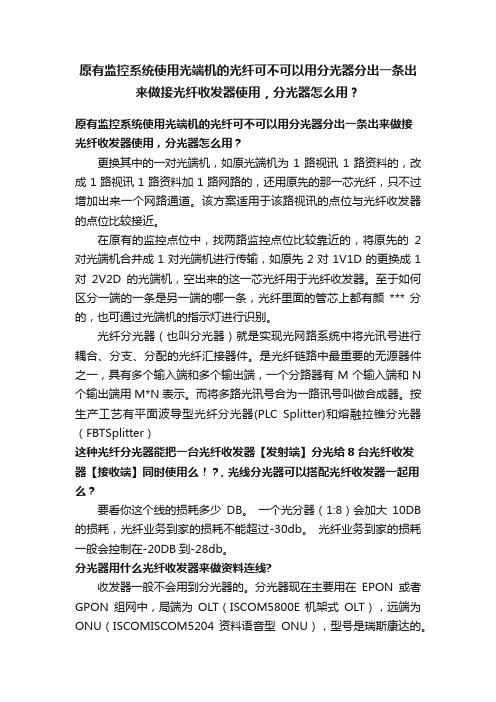
原有监控系统使用光端机的光纤可不可以用分光器分出一条出来做接光纤收发器使用,分光器怎么用?原有监控系统使用光端机的光纤可不可以用分光器分出一条出来做接光纤收发器使用,分光器怎么用?更换其中的一对光端机,如原光端机为1路视讯1路资料的,改成1路视讯1路资料加1路网路的,还用原先的那一芯光纤,只不过增加出来一个网路通道。
该方案适用于该路视讯的点位与光纤收发器的点位比较接近。
在原有的监控点位中,找两路监控点位比较靠近的,将原先的2对光端机合并成1对光端机进行传输,如原先2对1V1D的更换成1对2V2D的光端机,空出来的这一芯光纤用于光纤收发器。
至于如何区分一端的一条是另一端的哪一条,光纤里面的管芯上都有颜*** 分的,也可通过光端机的指示灯进行识别。
光纤分光器(也叫分光器)就是实现光网路系统中将光讯号进行耦合、分支、分配的光纤汇接器件。
是光纤链路中最重要的无源器件之一,具有多个输入端和多个输出端,一个分路器有M个输入端和N 个输出端用M*N表示。
而将多路光讯号合为一路讯号叫做合成器。
按生产工艺有平面波导型光纤分光器(PLC Splitter)和熔融拉锥分光器(FBTSplitter)这种光纤分光器能把一台光纤收发器【发射端】分光给8台光纤收发器【接收端】同时使用么!?, 光线分光器可以搭配光纤收发器一起用么?要看你这个线的损耗多少DB。
一个光分器(1:8)会加大10DB 的损耗,光纤业务到家的损耗不能超过-30db。
光纤业务到家的损耗一般会控制在-20DB到-28db。
分光器用什么光纤收发器来做资料连线?收发器一般不会用到分光器的。
分光器现在主要用在EPON或者GPON组网中,局端为OLT(ISCOM5800E 机架式OLT),远端为ONU(ISCOMISCOM5204 资料语音型ONU),型号是瑞斯康达的。
中兴、华为、烽火、格林韦迪等现在都有此类装置。
光纤收发器转分光器无法接多个B端!不可以。
光纤收发器是一对一的装置用华为MA5683T.一个光口可以分到64个。
- 1、下载文档前请自行甄别文档内容的完整性,平台不提供额外的编辑、内容补充、找答案等附加服务。
- 2、"仅部分预览"的文档,不可在线预览部分如存在完整性等问题,可反馈申请退款(可完整预览的文档不适用该条件!)。
- 3、如文档侵犯您的权益,请联系客服反馈,我们会尽快为您处理(人工客服工作时间:9:00-18:30)。
如何连接分光器
1常见问题
在部署探针及分光器时,常见的问题有二个:极性问题和光功率问题。
1.1 极性
下图示例说明了分光器与DTE、DCE网络设备的连接原理。
分光器只能对TX信号进行正确地分光,本图说明了采用正确的极性进行连接。
DCE Tx(DTE Rx)数据连接到探针采用蓝色标记,DTE Tx(DCE Rx)数据连接到探针的采用红色标记。
如果光缆在双向都接反了(即混合极性,mixed-polarity),用户原有的链路还可正常工作(DTE-Tx to DCE-Rx and DTE-Tx to DCE-Rx),但是分光器有时不能正常工作,探针可能接收到较低光功率的光信号或接收不到光信号(低于探针的光功率范围)。
一个不影响原有链路正常工作并检测混合极性的方法是测量分光器输出到探针的光功率。
若光功率非常低,多达-30db to -40db,就有可能是采用混合极性的连接方法。
若已经确认是混合极性问题,或想确认是否采用了混合极性接法,可采用以下方法:
[警告-此操作可能导致链路的中断]
1 –同时颠倒分光器A、B端口的连接,可能发生如下结果:
A: 探针接受到光功率增强,探针可以监控到数据[这表时原来是混全极性连接,现在是正确的连接方式]
或者
B: 探针接受到的光功率更弱了(现在是错误的混合极性连接)
恢复原来的连接方式并检查光缆的衰减,是否光接头有污或损坏的光缆。
2 –测量连接分光器的每根光缆和二根光缆的光功率:
A: 断开连接分光器的所有光缆并记录下连接的方式.
B: Take a light reading off of the Network “A” cable, then plug it into the tap in the same orientation as it was before and get the readings off the probe connections. [One will be "0" the other will have a value]
C: Now disconnect Network “A” , and repeat the above procedure with the cable from Network “B” - again you will get a valid reading and a "0".
D: Now connect BOTH cables and take a reading off of the probe-connectors
If the light level at the probe connectors is about the same as it was in A: and B: then you are connected correctly. If, however, you see a much greater difference (-15db or more) at the probe connectors when both cables are connected than with either side alone, then you have a mixed-polarity connection and should reverse the cables.
These polarity issues will not come up if you are using cables with polarized connectors at both ends of the cable.
1.2 光功率
2Netscout Probes的光学参数
NetScout makes a line of Fiber Optics probes for most mainstream circuits. The following tables reflect the light sensitivity of our different probes.
It should be noted that, as stated previously, there is a difference between the …typical‟ light level ranges that are found usable in a test laboratory environment and that of a production network where any downtime and/or failure are not acceptable. We therefore differentiate between the absolute range of light figures supplied from the vendors under which the optical receivers on the NICs are known to function, as opposed to the range of light under which we are confident of 100% performance and reliability. We list the minimum values for each probe, both the typical value and our own recommended value from field and customer experience.
It is this latter range that we strongly suggest be used and that readings on the …edge‟ of this suggested range be considered marginal. For example, we would consider a light reading for the 9100 model ATM OC3/OC12 probe of -26dBm to be a marginal level and would suggest raising it to –25dBm or better to insure reliable operation of the probe. Even though the manufacturer of the NIC receiver would suggest –30dBm is appropriate, we have found quite often that field experience does not bear this out when not in a lab. A 1dBM rise will equate to a 22% increase in light.
2.1 Netscout OC3 and OC12 ATM Probes:
Maximum light level NetScout Probe Model Typical Minimum range / Field
value suggested
8110 Multimode -30 to –31dBm / -26dBm -14dBm
8110 Singlemode ** -30 to –31dBm / -26dBm -14dBm
9110 Multimode -26 to –30dBm / -26dBm -14dBm
9110 Singlemode -28 to –31.5dBm / -26dBm -8dBm
-20dBm / -17dBm +4dBm
Gigabit (8900 and 9900
series)
Fast Ethernet (8213, 8243) -30dBm / -28dBm -10dBm
**Note: The 8110 Single-mode Probe uses a special Tap-to-Probe cable that
adds an additional 1dBm of signal loss.
2.2 NetScout POS Probes
The POS OC3/OC12 probes use the same receiver chip-sets as the ATM OC3/OC12 probes so they have the same light sensitivity
2.3 NetScout Gigabit Probes:
2.4 NetScout Fast Ethernet Probes:。