LDSPF系列三倍频发生器
BLSBF75三倍频电源发生器

BLSBF-7.5三倍频电源发生器使用说明书武汉博朗恒业电气有限公司一. 概述BLSBF-7.5三倍频发生器主要用于对被试品在不同电压及频率下的特性进行试验的场合。
全套装置体积小,装配方便,操作简便。
该装置的核心组件——变频电源柜采用高性能微处理器控制,全中文菜单显示,具有自动化程度高,保护迅速可靠,人机界面友好等优点。
该装置虽安装操作简便,但误操作仍会引起意外事故。
因此在使用前请务必仔细阅读本使用说明,以免对被试品及试验装置造成不必要的损坏。
二. 型号说明额定容量KVA 型号三. 产品交货检查及保修1. 交货检查用户在拆箱后,请立即进行以下检查: 1)是否在运输中造成损伤。
2)机种型号及资料与您所定的是否相符。
3)如有问题请您速与我公司联系。
同时说明产品型号、规格、产品编号、购买日期、破损程度等。
2. 产品保修本产品的保修期为三年。
但属下列情况将是有偿服务:1)因误操作或不适当的修理引起故障时。
2)超过标准使用而出现故障时。
3)购买后摔坏及运输中的损伤。
4)地震、火灾、水灾、雷击、电压异常以及其他天灾等造成的损伤。
四.主要技术参数1.三倍频电源1)额定输入电压:三相380V,50HZ2)输出电压:0-300V单相SPWM调制正弦波3)额定输出电流:25A4)额定输出功率:7.5KW5)效率:>85%6)频率调节范围:30.0-400.0HZ7) 最小频率调节步距:1HZ/0.1HZ8)输出波形畸变率:≤3%9)额定满负载下连续工作时间:15分钟10)运行噪声:≤60dB11)使用环境温度:-30ºC -- +40ºC五.注意事项1.请将变频电源柜安放于符合标准要求(温度、湿度、振动、尘埃)的场所。
2.每次使用前,请仔细检查,以避免发生接线错误。
3.请保持变频电源柜周围通风良好,以便降低变频电源柜环境温度。
4.在试验前,请将变频电源柜接地端(GND)可靠接地。
5.正式试验前,请将变频电源柜预热3-5分钟6.由于电路直流滤波电容器放电需要时间,所以即使已关断电源也不要立即关闭控制电源开关,否则会损坏变频电源的功率器件。
三倍频发生器使用操作方法
三倍频发生器使用操作方法
6.1 三倍频发生器按原理接好工作线路,注意发生器外壳、控制箱外壳及公共地线必须良好接地,不允许随意扎在自来水管道上,否则将危及人身与设备的安全。
6.2 按照被试品正常感应耐压所需的电流等级,耐压时间。
选设定好过流整定器、定时报警器的动作值。
6.3 准备完毕,检查线路无误后,可合上发生器总电源开关,电压表指示,打开控制箱回路电源开关,此时开关指示灯亮,表示电源已接通;同时红色停止按钮上的指示灯也亮,回零指示灯假如不亮,应把调压器手柄按逆时针方向返回零位,此时回零指示灯亮,否则起动按钮拒绝合闸。
6.4 三倍频发生器按下起动按钮,绿色按钮指示灯亮,这时按顺时针速度均匀缓慢地旋动调压器手柄,电压逐步上升,并密切注意电压表的指示及试品情况,直至调到所需试验电压为止。
6.5 要测试产品的耐压试验时间,可拨动定时器所需定时时间再按下定时与报警开关,即在规定的时间里测试产品耐压,然后报警告知,此时将调压器手柄回零,按下停止按钮,切除时间继电器开关,然后切断总电源开关。
尊敬的客户:
感谢您关注我们的产品,本公司除了有此产品介绍以外,还有红外线测温仪,变频串联谐振试验装置,大电流发生器,真空滤油机厂家,耐电压测试仪,无线高压核相仪等等的介绍,您如果对我们的产品有兴趣,欢迎来电咨询。
谢谢!。
三倍频发生器的基本原理

三倍频发生器的基本原理三倍频发生器是一种电子设备,它可以将输入的信号频率变为原信号的三倍频率。
在某些场合下,需要产生高频的电磁信号,而传统方法往往需要使用大量的器件或者复杂的实验操作。
使用三倍频发生器则可以简化这个过程,提高效率。
基本原理三倍频发生器的基本原理是通过倍频的方法实现信号的频率转换。
其中最简单的实现方式就是使用全波整流电路和电容滤波器。
在全波整流电路中,采用了恒流源和电容器的电路,将输入的交流信号转换为直流信号,然后将其通过电容滤波器进行滤波,获得了一个直流电位。
接下来再通过倍频电路将其输出的频率变为原信号的三倍频率。
倍频电路倍频电路是实现三倍频发生器的核心部件,它可以将输入的信号进行频率提升。
其中最常见的方式是使用倍频器电路。
倍频器电路倍频器电路分为李-基二倍频电路和倍频振荡器两种类型。
它们的基本原理是使用二级倍频电路来产生更高频率的电信号。
在李-基二倍频电路中,输入信号首先会进入一个二极管桥整流器,将正负半周期的信号分别整流,并将其输入到一个差分放大器中。
差分放大器会将两个信号相加,然后将其输入到一个输出振荡器中,产生高频信号。
最后,再将这个信号反馈到差分放大器的负端,使其形成一个闭环,从而实现三倍频输出。
而在倍频振荡器中,则是通过基础的压控振荡器和倍频器电路相结合来实现三倍频输出。
通过调整振荡器的频率,使其与倍频器之间在一定倍频系数的情况下实现三倍频输出。
总结在实现三倍频信号输出的过程中,倍频电路是实现这个过程的核心部件。
在电路的设计中,需要选择合适的器件和电路结构,以保证输出的信号质量和稳定性,并且能够满足不同场合的要求。
除此之外,中频放大器和输出滤波器等其他器件也是影响三倍频输出效果的关键部分。
永林电子 LDX-305A 三回路 LED 调光器 【说明书】
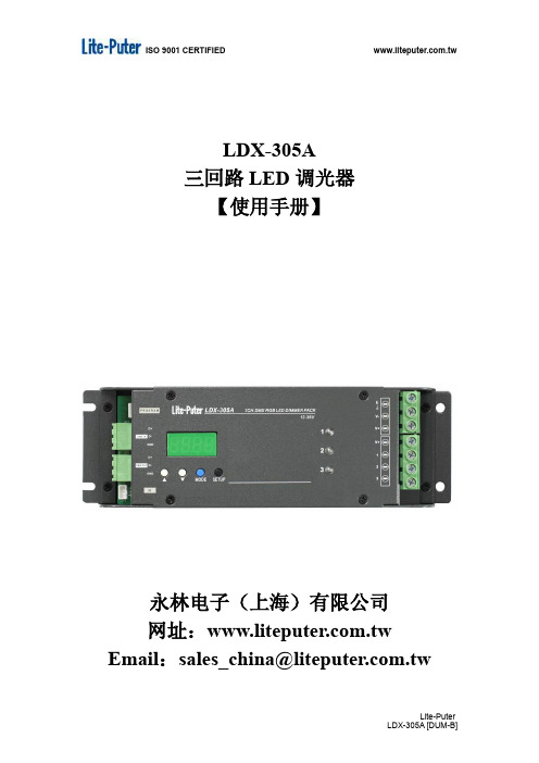
LDX-305A三回路LED调光器【使用手册】永林电子(上海)有限公司网址: Email:*************************.tw目录1 系统简介 (1)1-1特点 (1)1-2规格 (1)1-3操作面板功能简介 (1)2 系统操作说明 (2)2-1内建模式的设定与呼叫 (2)2-2设备区域的设定 (2)2-3ID NO.的设定 (3)2-4设定场景对应各内建模式 (3)2-5DMX控制设定 (4)2-6内建跳机的SPEED调整设定 (4)2-7DMX地址的设定 (5)2-8单回路LEVEL查看与自定颜色的设定 (5)2-9智能模式的选定 (5)2-10红外遥控面板上的设置 (7)2-11接受控制面板控制 (8)2-12内建模式 (9)品质保证 (10)1 系统简介1-1 特点●可输出3个控制回路●模块化设计、维护更加容易●可接收标准DMX512讯号控制●LED显示接口,操作更加简单●可接受红外线遥控面板控制●可接受ECP系列面板控制1-2 规格●电源供应:12 - 28V DC●输出规格:每回路可输出5A●数字信号输入:DMX-512●传输速率:250K bps●数字信号连接头:3PIN绿色端子●外观尺寸:234 ( W ) X 75 ( H ) X 40 ( D ) mm●重量:0.4 kg●保险丝说明:PCB板号RD22A1 F4,F5(自復式保险丝0.1A 60V)F1-F3(管状保险丝6A,250V). 1-3 操作面板功能简介2 系统操作说明2-1 内建模式的设定与呼叫按下【MODE 】一次,进入选择内建模式接口,按下【SETUP 】,保存所选内建模式,退回到主画面,机器此时会呼叫出该内建跳机。
注意: LDX-305A 共有39种内建模式,请参考2-12。
2-2 设备区域的设定】两次,则LED 会显示这台机器的区域, 按下【▲】或【▼】修改ZONE 数值,设定完成后,再次按下【MODE 】,保存ZONE 设定并进入回路 设定。
CA30CAN CAF 4TH 代三重保护电容接近传感器说明书

Proximity Sensors Capacitive Thermoplastic Polyester Housing Types CA30CAN/CAF.....• 4TH Generation TRIPLESHIELD TM• Adjustable sensing distance: 2 - 20 mm Flush or 4-30 mm Non-flush• Protection: short-circuit, transients and reverse polarity • Dust and humidity compensation • Dust or Temperature alarm output • Rated operational voltage: 10-40 VDC • Output: DC 200 mA, NPN or PNP • Standard Output: NO and NC• LED indications for Power-supply, Output and Stability • IP67, IP68, IP69K, Nema 1, 2, 4, 4X, 5, 6, 6P, 12• Cable and M12 connector versions availableProduct DescriptionThe CA30CA.. capacitive proximity switches feature an improved 4TH Genera-tion TRIPLESHIELD TM tech-nology. F urthermore, these sensors feature increased immunity to electromagnetic inteference (EMI), especial-ly to frequency drives. Not only does 4TH Generation TRIPLESHIELD TM feature an increased EMI, but it also increases the immuni-ty to humidity and dust. The implementation of stability indication eases the setup procedure as both Stable ON and Stable OFF positions are indicated by the Green and yellow LEDs.increased by 20 – 25 % allowing room for additional stable detection.gives an early warning that have to be cleaned.The Temperature alarm func-tion raises an alarm if the sensing surface goes beyond 60 degree celcius.The sensor housing is featur-ing IP69K as well as approval by ECOLAB for cleaning- and disinfection agents.Rated operating distance (S n ) Non-flush mounted sensor 0 - 25 mm (factory setting 25 mm), (ref. target 75x75 mm ST37, 1 mm thick, grounded) Flush mounted sensor 0 - 16 mm (factory setting 16 mm - non-flush mounted) (ref. target 48x48 mm ST37, 1 mm thick, grounded)Specifications EN 60947-5-2Housing Sensor Output Output ConnectionRated operating Ordering no. Ordering no. Ordering no.diameter type type function distance (S n ) StandardDust alarmTemperature alarmM 30 Flush NPN NO+NC Cable 0 - 16 mm CA30CAF16NA M 30 Flush NPN NO+NC M12 Plug 0 - 16 mm CA30CAF16NAM1M 30 Flush PNP NO+NC Cable 0 - 16 mm CA30CAF16PA M 30 Flush PNP NO+NC M12 Plug 0 - 16 mm CA30CAF16PAM1M 30 Flush PNP NO Cable 0 - 16 mm CA30CAF16PODU CA30CAF16POTAM 30 Flush PNP NC Cable 0 - 16 mmCA30CAF16PCDU CA30CAF16PCTA M 30 Flush PNP NC M12 Plug 0 - 16 mm CA30CAF16PCM1DUM 30 Non-Flush NPN NO+NC Cable 0 - 25 mm CA30CAN25NA M 30 Non-Flush NPN NO+NC M12 Plug 0 - 25 mm CA30CAN25NAM1M 30 Non-Flush PNP NO+NC Cable 0 - 25 mm CA30CAN25PA M 30 Non-Flush PNP NO+NC M12 Plug 0 - 25 mm CA30CAN25PAM1M 30 Non-Flush PNP NO Cable 0 - 25 mm CA30CAN25PODU CA30CAN25POTA M 30Non-FlushPNPNCCable0 - 25 mmCA30CAN25PCDU CA30CAN25PCTAType SelectionCA30CAN/CAF.....Specifications (cont.) EN 60947-5-2* The IP69K test according to DIN 40050-9 for high-pressure, high-temperature wash-down applications. The sensor must not only be dust tight (IP6X), but also able to withstand high-pressure and steam cleaning. The sensor is exposed to high pressure water from a spray nozzle that is fed with 80°C water at 8’000– 10’000 KPa (80–100bar) and a flow rate of 14–6L/min. The nozzle is held 100 –150 mm from the sensor at angles of 0°, 30°, 60° and 90° for 30s each. The test device sits on a turntable that rotates with a speed of 5 times per minute. The sensor must not suffer any damaging effects from the high pressure water in appear-ance and function.90°60°30°0°The environments in which capacitive sensors are in s tall e d can often be un s ta-ble as regards to tempera-ture, humi d ity , object dis-tance and industrial (noise) inter f erence. Because of this, Carlo Ga v azzi offers as standard features in all TRIPLESHIELD TM capacitive sensors a user-friendly sen-sitivity adjustment instead of a fixed sensing range. Likewise, these sensors provide an extend e d sen-sing range to accommodatemechanically de m and i ng are-as and tem p erature stability to en s ure high immunity to elec t ro m agnetic interference (EMI) and a minimum need for adjusting sensitivity if the temperature varies.Note:Sensors are factory set (default) to nominal sensing range S n .Adjustment GuideCA30CAN/CAF.....Wiring DiagramDetection DiagramCA30CAN/CAF.....Detection Stability IndicationDimensionsInstallation HintsCapacitive sensors have a unique ability to detect al-most any material in li q uid or solid form. Capa c i t ive sen-sors are able to detect me-tallic as well as non-metallic ob j ects. How e ver, their tradi-tional use is for non-metallic materials such as:• Plastics Industry Resins, regrinds or mould-ed products.• Chemical IndustryCleansers, fertilizers, liq-uid soaps, corrosives andpe t r o c hemicals.• Wood IndustrySaw dust, paper products,door and window frames.• Ceramics & GlassI ndustryRaw materials, clay orfinish e d products, bottles.• Packaging IndustryPackage inspection for lev-el or contents, dry goods,fruits and vegetables, dairyproducts.Materials are detected due totheir dielectric constant. Thebigger the size of an object,the higher the density of ma-terial, the better or easier it isto detect the object.The nominal sensing di s tan-ce for a capacitive sensoris refe r r ed to a groundedme t al plate (ST37). For addi-tional information regardingdi e lec t ric ratings of materi-als please re f er to TechnicalInformation.Relief of cable strain Protection of the sensing face Switch mounted on mobile carrier To avoid interference from inductive voltage/current peaks, separate the prox. switch pow-er cables from any other power cables, e.g.motor, contactor or solenoid cablesNot correctCorrectThe cable should not be pulled A proximity switch should not serve asmechanical stopAny repetitive flexing of thecable should be avoided Delivery Contents•Capacitive switch: CA30CAN/CAF.......• User manual• 2 x M30 fingernuts• Screwdriver• Packaging: Cardboard boxAccessories• Connector type CONM14NF.. -series.• Mounting Brackets AMB30-S.. (straight),AMB30-A.. (angled)CA30CAN/CAF.....。
Mornsun LS05-23BxxDR3 高功率 AC DC 转换器说明书

5W,DIY AC/DCconverterRoHSEN62368-1FEATURES●Ultra-wide 85-305VAC and 70-430VDC input voltage range ●Accepts AC or DC input (dual-use of same terminal)●Operating ambient temperature range:-40℃to +85℃●High I/O isolation test voltage up to 4000VAC●Multi application,compact size,flexible layout ●No-load power consumption 0.1W●Output short circuit,over-current protection ●Plastic case meets UL94V-0flammability ●Pollution level Ⅲ(meet IEC62368-1)LS05-23BxxDR3series is one of Mornsun’s miniaturized potting highly efficient green power AC-DC Converters.They feature wide input range accepting either AC or DC voltage,high reliability,low power consumption,reinforced isolation and strong applicability.All models are particularly suitable for industrial control,electric power,instrumentation and smart home applications which have high requirement for dimension and don’t have high requirement on EMC.For extremely harsh EMC environment,we recommend using the application circuit show in Design Reference of this datasheet.Input SpecificationsItemOperating Conditions Min.Typ.Max.Unit Input Voltage Range AC input 85--305V AC DC input70--430VDC Input Frequency 47--63HzInput Current 115V AC ----0.2A 230V AC ----0.1Inrush Current115V AC --20--230V AC--40--Recommended External Input Fuse 1A,slow-blow,required(The actual use needs to be selected according to the application enviroment)Hot PlugUnavailableOutput SpecificationsItemOperating Conditions Min.Typ.Max.UnitOutput Voltage Accuracy 10%-100%load --±5--%Line Regulation Rated load --±1.5--Load Regulation 10%-100%load--±3--Ripple &Noise *20MHz bandwidth (peak-to-peak value),10%-100%load--80150mV Temperature Coefficient --±0.15--%/°C Stand-by Power Consumption230V AC--0.100.15W Selection GuideCertificationPart No.Output PowerNominal Output Voltage and Current (Vo/Io)Efficiency at 230V AC(%)Typ.Capacitive Load(uF)Max.ENLS05-23B03DR3 3.3W3.3V/1000mA 682200LS05-23B05DR35W 5V/1000mA 711500LS05-23B09DR39V/560mA 74680LS05-23B12DR312V/420mA 75470LS05-23B15DR315V/340mA 77330LS05-23B24DR324V/210mA77100Note:The nominal output voltage refers to the voltage applied to the load terminal after adding external circuits.Short Circuit Protection Hiccup,continuous,self-recovery Over-current Protection≥110%Io,self-recovery Minimum Load10----%Hold-up Time 115V AC input--8--ms 230V AC input--40--Note:1.*The“parallel cable”method is used for ripple and noise test,please refer to AC-DC Converter Application Notes for specific information;2.The product is able to work with0%-10%load and with stable output.General SpecificationsItem Operating Conditions Min.Typ.Max.UnitIsolation Input-output Electric Strength Test for1min.,leakage current<5mA4000----VACInsulation Resistance Input-output At500VDC100----MΩOperating Temperature-40--+85℃Storage Temperature-40--+105Storage Humidity----95%RHPower Derating +55℃to+85℃ 1.67----%/℃85V AC-100VAC 1.33----%/V AC 277V AC-305V AC0.72----Safety Standard Design refer to IEC/UL62368-1,IEC/EN60335-1, IEC/EN61558-1&EN62368-1(Report)Safety Class CLASS IIMTBF MIL-HDBK-217F@25°C>1,000,000h Mechanical SpecificationsCase Material Black plastic,flame-retardant and heat-resistant(UL94V-0)Dimension27.60x18.50x7.80mmWeight7.5g(Typ.)Cooling method Free air convectionElectromagnetic Compatibility(EMC)Emissions CECISPR32/EN55032CLASS A(Application circuit1,4)CISPR32/EN55032CLASS B(Application circuit2,3,5) RECISPR32/EN55032CLASS A(Application circuit1,4)CISPR32/EN55032CLASS B(Application circuit2,3,5)Immunity ESD IEC/EN61000-4-2Contact±6KV/Air±8KV Perf.Criteria B RS IEC/EN61000-4-310V/m perf.Criteria AEFTIEC/EN61000-4-4±2KV(Application circuit1,2)perf.Criteria BIEC/EN61000-4-4±4KV(Application circuit3,4,5)perf.Criteria BSurgeIEC/EN61000-4-5line to line±1KV(Application circuit1,2)perf.Criteria BIEC/EN61000-4-5line to line±2KV(Application circuit3,4)perf.Criteria BIEC/EN61000-4-5line to line±2KV/line to ground±4KV(Application circuit5)perf.Criteria BCS IEC/EN61000-4-610Vr.m.s perf.Criteria A Voltage dip,shortinterruption and voltagevariationIEC/EN61000-4-110%,70%perf.Criteria AProduct Characteristic CurveNote:①With an AC input between85-100VAC/277-305VAC and a DC input between70-120VDC/390-430VDC,the output power must be derated as per temperature derating curves;②This product is suitable for applications using natural air cooling;for applications in closed environment please consult factory oroneof our FAE. Additional Circuits Design ReferenceLS series additional circuits design referenceLS05series additional components selection guide(No EMC devices)Part No.C1(required)C2(required)L1(required)C3(required)C4CY1(required)TVSLS05-23B03DR310uF/450V(-25℃to+85℃,85-305VAC input;-40℃to+85℃,165-305VAC input)22uF/450V(-40℃to+85℃,85-305VAC input)820uF/6.3V(solid-state capacitor) 2.2uH/36mΩ/3.3A220uF/16V0.1uF/50V1.0nF/400V ACSMBJ7.0ALS05-23B05DR3470uF/16V(solid-state capacitor)LS05-23B09DR347uF/35V SMBJ12ALS05-23B12DR3270uF/16V(solid-state capacitor)4.7uH/60mΩ/2.2A SMBJ20ALS05-23B15DR3220uF/25V(solid-state capacitor)LS05-23B24DR3220uF/35V SMBJ30A Note:1.C1is used as filter capacitor with AC input(must be connected externally)and as EMC filter capacitor with DC input(must be connected),and it is recommended to use the capacitor with ripple current>200mA@100KHz.2.We recommend using an electrolytic capacitor with high frequency and low ESR(ESR of C3at low temperature of-40℃≤1.1Ω)rating for C3(refer to manufacture’s datasheet),electrolytic capacitor can be used for C2when applied in normal and high temperature bined with C2,L1,they form a pi-type filter circuit.Choose a capacitor voltage rating with at least20%margin,in other words not exceeding80%.C4is a ceramic capacitor,used for filtering high frequency noise.3.A suppressor diode(TVS)is recommended to protect the application in case of converter failure and specification should be1.2times of the output voltage.Environmental Application EMC SolutionLS series environmental application EMC solution selection tableRecommendedcircuitApplicationenvironmental Typical industryInput voltagerangeEnvironmenttemperature Emissions Immunity1Basic application None85-305V AC -40℃to+85℃CLASS A CLASSⅢ2Indoor civilenvironmentSmart home/Home appliances(2Y)-25℃to+55℃CLASS B CLASSⅢIndoor generalenvironmentIntelligent building/Intelligentagriculture3Indoor industrialenvironment Manufacturing workshop-25℃to+55℃CLASS B CLASSⅣ4Outdoor generalenvironmentITS/Video monitoring/Chargingpoint/Communication/Securityand protection-40℃to+85℃CLASS A CLASSⅣ5OutdoorindustrialenvironmentElectricity/Grid-40℃to+85℃Class B CLASSⅣElectromagnetic Compatibility Solution--Recommended Circuit1.Application circuit1——Basic applicationApplication circuit1Application environmental Ambient temperature range Immunity CLASS Emissions CLASS Basic application-40℃to+85℃CLASSⅢCLASS AFUSE1A/300V,slow-blow,requiredR124Ω/3W(wire-wound resistor,required)LDM 4.7mH/Max:15Ω/Min:0.2A Note:R1is the input plug-in resistor,this resistor needs to be a wire-wound resistor(required),please do not select chip resistor or carbon film resistor. 2.Application circuit2——Universal system recommended circuits for indoor civil/general environmentApplication circuit2Application environmental Ambient temperature range Immunity CLASS Emissions CLASS Indoor civil/general-25℃to+55℃CLASSⅢCLASS BComponent Recommended valueR124Ω/3W(wire-wound resistor,required)LDM 4.7mH/Max:15Ω/Min:0.2ACX0.1uF/310VACFUSE1A/300V,slow-blow,required Note1:In the home appliance application environment,the two Y capacitors of the primary and secondary need to be externally connected (CY1/CY2,value at2.2nF/250VAC),which can meet the EN60335certification.Note2:According to the certification requirements,the X capacitor needs to be connected in parallel with the bleeder resistance,the recommended resistance value is less than3.8MΩ,and the actual need to be selected according to the certification standard.Note3:R1is the input plug-in resistor,this resistor needs to be a wire-wound resistor(required),please do not select chip resistor or carbon film resistor. 3.Application circuit3——Universal system recommended circuits for indoor industrial environmentApplication circuit3Application environmental Ambient temperature range Immunity CLASS Emissions CLASSIndoor industrial-25℃to+55℃CLASSⅣCLASS BComponent Recommended valueMOV S14K350CX0.1uF/310V ACLDM 4.7mH/Max:15Ω/Min:0.2AR133Ω/3W(wire-wound resistor,required)FUSE2A/300V,slow-blow,required Note1:According to the certification requirements,the X capacitor needs to be connected in parallel with the bleeder resistance,the recommended resistance value is less than3.8MΩ,and the actual need to be selected according to the certification standard.Note2:R1is the input plug-in resistor,this resistor needs to be a wire-wound resistor(required),please do not select chip resistor or carbon film resistor. 4.Application circuit4——Universal system recommended circuits for outdoor general environmentApplication circuit4Application environmental Ambient temperature range Immunity CLASS Emissions CLASSOutdoor general environment-40℃to+85℃CLASSⅣCLASS AComponent Recommended valueMOV S14K350LDM 4.7mH/Max:15Ω/Min:0.2AR133Ω/3W(wire-wound resistor,required)FUSE2A/300V,slow-blow,required Note:R1is the input plug-in resistor,this resistor needs to be a wire-wound resistor(required),please do not select chip resistor or carbon film resistor.5.Application circuit5——Universal system recommended circuits for outdoor industrial environmentApplication circuit5Application environmental Ambient temperature range Immunity CLASS Emissions CLASSOutdoor industrial environment-40℃to+85℃CLASSⅣCLASS BComponent Recommended valueC122uF/450VMOV S14K350CX0.1uF/310V ACLDM330uH/960mΩMax/0.31ALCM 3.1mHR147Ω/5W(wire-wound resistor,required)CY3/CY41nF/400V ACFUSE2A/300V,slow-blow,required Note1:According to the certification requirements,the X capacitor needs to be connected in parallel with the bleeder resistance,the recommended resistance value is less than3.8MΩ,and the actual need to be selected according to the certification standard.Note2:R1is the input plug-in resistor,this resistor needs to be a wire-wound resistor(required),please do not select chip resistor or carbon film resistor.6.For additional information please refer to application notes on . Dimensions and Recommended LayoutLS05-23BxxDR3series dimensionsLS05-23BxxDR3series recommended padNote:There is a slot(non-metallic hole)between pin4/5.For details,please refer to the recommended dimensions or pad.Note:1.For additional information on Product Packaging please refer to .Packaging bag number:58220074;2.External electrolytic capacitors are required to modules,more details refer to typical applications;3.This series is a potting product,at least6.4mm creepage distance between the primary and secondary external components of themodule is needed to meet the safety requirement,refer to the recommended welding hole design in the external dimension drawing;4.Unless otherwise specified,parameters in this datasheet were measured under the conditions of Ta=25℃,humidity<75%,nominal inputvoltage(115V and230V)and rated output load;5.All index testing methods in this datasheet are based on our company corporate standards;6.We can provide product customization service,please contact our technicians directly for specific information;7.Products are related to laws and regulations:see"Features"and"EMC";8.Our products shall be classified according to ISO14001and related environmental laws and regulations,and shall be handled byqualified units.Mornsun Guangzhou Science&Technology Co.,Ltd.Address:No.5,Kehui St.1,Kehui Development Center,Science Ave.,Guangzhou Science City,Huangpu District,Guangzhou,P.R.China Tel:86-20-38601850Fax:86-20-38601272E-mail:***************。
(整理)常用三极管大全及功能

精品文档2011.3.10品名极性管脚功能参数MPSA42NPN21E电话视频放大300V0 .5A0 .625W MPSA92PNP21E电话视频放大300V0 .5A0 .625W MPS2222A NPN21高频放大75V0 .6A0 .625W300MHZ 9011NPN EBC高频放大50V30mA0 .4W150MHz 9012PNP贴片低频放大50V0 .5A0 .625W 9013NPN EBC低频放大50V0 .5A0 .625W 9013NPN贴片低频放大50V0 .5A0 .625W 9014NPN EBC低噪放大50V0 . 1A0 .4W150MHZ 9015PNP EBC低噪放大50V0 . 1A0 .4W150MHZ 9018NPN EBC高频放大30V50MA0 .4W1GHZ 8050NPN EBC高频放大40V1 .5A1W100MHZ 8550PNP EBC高频放大40V1 .5A1W100MHZ2N2222NPN4A高频放大60V0 .8A0 .5W25/200NSβ=45 2N2222A NPN小铁高频放大75V0 .6A0 .625W300MHZ 2N2369NPN4A开关40V0 .5A0 .3W800MHZ2N2907NPN4A通用60V0 .6A0 .4W26/70NSβ=200 2N3055NPN12功率放大100V15A115W2N3440NPN6视放开关450V1A1W15MHZ2N3773NPN12音频功放开关160V16A150W COP 2N6609 2N3904NPN21E通用60V0 .2Aβ=100-4002N3906PNP21E通用40V0 .2Aβ=100 -4002N5401PNP21E视频放大160V0 .6A0 .625W100MHZ 2N5551NPN21E视频放大160V0 .6A0 .625W100MHZ 2N5685NPN12音频功放开关60V50A300W2N6277NPN12功放开关180V50A250W精品文档2N6609 2N6678 2N6718 3DA87A 3DG6A 3DG6B 3DG6C 3DG6D 3DG12C 3DK2B 3DK4B 3DK7C 3DD15D 3DD102C 3522V A634 A708 A715C A733 A741 A781 A928 A933 A940 A950 A966 A968 A1009 A1012PNP 12 音频功放开关 160V15A150W COP 2N3773 NPN 12 音频功放开关 650V15A175W15MHZ NPN 小铁音频功放开关 100V2A2W50MHZNPN 6 视频放大 100V0 . 1A1WNPN 6 通用 15V20mA0 . 1W100MHz NPN 6 通用 20V20mA0 . 1W150MHz NPN 6 通用 20V20mA0 . 1W250MHz NPN 6 通用 30V20mA0 . 1W150MHz NPN 7 通用 45V0 .3A0 .7W200MHz NPN 7 开关 30V30mA0 .2WNPN 7 开关 40V0 .8A0 .7WNPN 7 开关 25V50mA0 .3WNPN 12 电源开关 300V5A50WNPN 12 电源开关 300V5A50W5 .2V 稳压管录像机用PNP 28E 音频功放开关 40V2A10WPNP 6 NF/S 80V0 .7A0 .8WPNP 29 音频功放开关 35V2 .5A10W160MHZ PNP 21 通用 50V0 . 1A180MHZPNP 4 S 20V0 . 1A <70/120nS PNP 39B 开关 20V0 .2A <80/160NS PNP ECB 通用 20V1A0 .25WPNP 21 Uni 50V0 . 1A140MHzPNP 28 音频功放开关 150V1 .5A25W4MHZ /C2073 PNP 21 通用 30V0 .8A0 .6WPNP 21 音频激励输出 30V1 .5A0 .9W COP:C2236 PNP 28 音频功放开关 160V1 .5A25W100MHZ /C2238 PNP BCE 功放开关 350V2A15WPNP 28 音频功率放 60V5A25W精品文档A1013 A1015 A1020 A1123 A1162 A1216 A1220 A1265 A1295 A1301 A1302 A1358 ? A1444 A1494 A1516 A1668 A1785 A1941 A1943 A1988 B449 B631K B647 B649 B669 B673 B675PNPPNPPNPPNPPNPPNPPNPPNPPNPPNPPNPPNPPNPPNPPNPPNPPNPPNPPNPPNPPNPPNPPNPPNPPNPPNPPNP2121212121dBCE29BCEBCEBCEBCEBCEBCEBCE28BBCEBCEBCE3012292129282828视频放大通用音频开关低噪放大通用贴片功放开关音频功放开关功放功放功放功放开关开关开关开关高频高速电源开关功放开关功放开关电源开关驱动功放开关功放开关功放开关功放开关音频功放开关通用视放达林顿功放达林顿功放达林顿功放160V1A0 .9W60V0 . 15A0 .4W8MHZ50V2A0 .9W150V0 .05A0 .75W50V0 . 15A0 . 15W180V17A200W20MHZ /2922120V1 .5A20W150MHZ/C2690140V10A100W30MHZ /C3182230V17A200W30MHZ /C3264160V10A100W30MHZ /C3280200V15A150W30MHZ /C3281120V1A10W120MHZ100V15A30W80MHZ200V17A200W20MHZ /C3858180V12A130W25MHZ200V2A25W20MHZ400V1A1W/120V1A0 .9W140MH140V10A100WCOP:5198230V15A150W /C5200 原50V3 .5A22 .5W 锗管120V1A8W130MHZ /D600K120V1A0 .9W140MHZ /D667180V1 .5A1W /D66970V4A40W100V7A40W60V7A40W精品文档B688PNP BCE音频功放开关120V8A80W /D718 B734PNP39B通用60V1A1W /D774B744PNP21通用30V0 . 1A0 .25WB772PNP29音频功放开关40V3A10WB774PNP21通用30V0 . 1A0 .25WB817PNP30功放开关160V12A100W /D1047 B834PNP28功放开关60V3A30WB937A PNP功放开关60V2A35 DRALB1020PNP28功放开关达林顿 100V7A40Wβ=6000 B1079PNP30达林顿功放100V20A100Wβ=5000/D1559 B1185PNP28B功放开关60V3A25W 70MHZ /D1762 B1238PNP ECB功放开关80V0 .7A1W 100MHZ B1240PNP39B功放开关40V2A1W100HZ B1243PNP39B功放开关40V3A1W70HZB1316PNP54B驱动功放达林顿 100V2A10Wβ=15000 B1317PNP BCE音频功放180V15A150W COP:D1975 B1335PNP28音频功放低噪80V4A30W 12MHZ B1375PNP BCE音频功放60V3A2W9MHZB1400PNP28B达林顿功放120V6A25W β=1000 -20000 B1429PNP BCE功放开关180V15A150WB1494PNP BCE达林顿功放120V25A120Wβ=2000 -20000 C106NPN EBC音频功放开关60V1 .5A15WC380NPN21高频放大35V0 .03A250MHZ C458NPN21通用30V0 . 1A230MHzC536NPN21通用40V0 . 1A180MHZ C752NPN21通用30V0 . 1A300MHzC815NPN21通用60V0 .2A0 .25WC828NPN21通用45V0 .05A0 .25W精品文档C900NPN21低噪放大30V0 .03A100MHZ C943NPN4A通用60V0 .2A200MHZ C945NPN21通用50V0 . 1A0 .5W250MHZ C1008NPN6通用80V0 .7A0 .8W50MHZ C1162NPN29音频功放开关35V1 .5A10WC1213NPN39B监视器专用35V0 .5A0 .4W C1222NPN21低噪放大60V0 . 1A100MHZC1494 ?NPN40A发射36V6A PQ=40W/175MHZ C1507NPN28视放300V0 .2A15W C1674NPN21HF/ZF30V0 .02A600MHz C1815NPN21通用60V0 . 15A0 .4W8MHZ C1855NPN21f HF/ZF20V0 .02A550MHz C1875NPN12彩行1500V3 .5A50W C1906NPN21高频放大30V0 .05A1000MHZ C1942NPN12彩行1500V3A50WC1959NPN21通用30V0 .4A0 .5W300MHz C1970NPN28手机发射40V0 .6A PQ=1 .3W/175MHZ C1971NPN28A手机发射35V2 .0A PQ=7 .0W/175MHZ C1972NPN28A手机发射35V3 .5A PQ=15W/175MHZ C2012NPN21HF30V0 .03A200MHZ C2027NPN12行管1500V5A50WC2036C2068NPN28E视频放大300V0 .05A1 .5W80MHZ C2073NPN28功率放大150V1 .5A25W4MHZ /A940 C2078NPN28音频功放开关80V3A10W150MHZ C2120NPN21通用30V0 .8A0 .6W C2228NPN21视频放大160V0 .05A0 .75W C2230NPN21视频放大200V0 . 1A0 .8W C2233NPN28音频功放开关200V4A40W精品文档C2236NPN21通用30V1 .5A0 .9W /A966 C2238NPN28音频功放开关160V1 .5A25W100MHZ /A968 C2320NPN21通用50V0 .2A0 .3W200MHZ C2335NPN28视频功放500V7A40WC2373NPN28功放200V7 .5A40WC2383NPN21视频开关160V1A0 .9W /A1015 C2443NPN大铁功放开关600V50A400WC2481NPN29音频功放开关150V1 .5A20WC2482NPN21视频放大300V0 . 1A0 .9WC2500NPN21通用30V2A0 .9W150MHZ C2594NPN29音频功放开关40V5A10WC2611NPN29视频放大300V0 . 1A1 .25WC2625NPN30音频功放开关450V10A80WC2682NPN29NF/Vid180V0 . 1A8WC2688NPN29视放管300V0 .2A10W80MHZ C2690NPN29音频功放开关120V1 .2A20W150MHZ/A1220P C2751NPN BCE电源开关500V15A120Wβ=40 C2837NPN30音频功放开关150V10A100WC2898NPN28音频功放开关500V8A50WC2922NPN43音频功放开关180V17A200W50MHZ /A1216 C3026NPN12开关管1700V5A50Wβ=20 C3030NPN BCE开关管达林顿 900V7A80Wβ=15 C3039NPN28电源开关500V7A50Wβ=40 C3058NPN12开关管600V30A200W β=15 C3148NPN28电源开关900V3A40Wβ=15 C3150NPN28电源开关900V3A50Wβ=15 C3153NPN30电源开关900V6A100Wβ=15 C3182NPN30功放开关140V10A100Wβ=95/A1265 C3198NPN21高频放大60V0 . 15A0 .4W130MHZ精品文档C3262NPN BCE达林顿功放800V10A100WC3264NPN BCE PA 功放开关230V17A200Wβ=170/A1295 C3280NPN30音频功放开关160V12A120Wβ=100 C3281NPN30音频功放开关200V15A150W30MHZβ=100 C3300NPN30音频功放开关100V15A100W β=600 C3310NPN28C电源开关500V5A40W β= 20 C3320NPN28C电源开关500V15A80W β= 15 C3355NPN21F高频放大20V0 . 1A6500MHZ C3358NPN40B高频放大20V0 . 1A7000MHZ C3457NPN BCE电源开关1100V3A50Wβ=12 C3460NPN BCE电源开关1100V6A100Wβ=12 C3466NPN BCE电源开关1200V8A120Wβ=10 C3505NPN28B电源开关900V6A80W β=20 C3527NPN BCE电源开关500V15A100Wβ=13 C3528NPN BCE电源开关500V20A150Wβ=13 C3595NPN29射频30V0 .5A1 .2Wβ=90 C3679NPN BCE电源开关900V5A100W6MHZ C3680NPN BCE电源开关900V7A120W6MHZ C3688NPN BCE彩行1500V10A150W C3720NPN BCE彩行1200V10A200W C3783NPN BCE高压高速开关900V5A100W 黄河 21"C3795NPN BCE高压高速开关900V5A2W8MHz C3807NPN BCE低噪放大30V2A1 .2W260MHZ C3858NPN BCE功放开关200V17A200W20MHZ /A1494 C3866NPN BCE高压高速开关900V3A40WC3873NPN BCE高压高速开关500V12A75W30MHZ C3886NPN BCE开关,行管1400V8A50W8MHZ C3893NPN28B行管1400V8A50W8MHZ C3907NPN28B功放开关180V12A130W30MHZ精品文档C3953NPN29视放120V0 .2A1 .3W 4000MHZ C3987NPN28达林顿50V3A20W β=1000 C3995NPN BCE行管1500V12A180W 34 寸C3997NPN BCE行管1500V15A250W C3998NPN BCE行管1500V25A250W C4024NPN BCE功放开关100V10A35W 24MHZ C4038NPN BCE门电路50V0 . 1A0 .3W180MHZ C4059NPN BCE高速开关600V15A130W 0 .5/2 .2US C4106NPN BCE电源开关500V7A50W20MHZ?C4111NPN BCE开关行管1500V10A150W C4119NPN BCE微波炉开关1500V15A250W C4231NPN50C音频功放800V2A30W C4237NPN BCE高压高速开关1000V8A120W30MHZ C4242NPN BCE高压高速开关450V7A40W C4288NPN BCE行管1400V12A200W8MHZ C4297NPN BCE电源开关500V12A75W10MHZ C4429NPN BCE电源开关1100V8A60W C4517NPN BCE音频功放550V3A30W6MHZ C4532NPN BCEC4582NPN28b电源开关600V15A75W20MHZ ON4673NPN BCEON4873NPN BCEC4706NPN BCE电源开关900V14A130W6MHz C4742NPN46彩行1500V6A50W(带阻尼) C4745NPN46彩行1500V6A50W C4747NPN46彩行1500V10A50W C4769NPN BCE微机行管1500V7A60W(带阻尼) C4913NPN BCE大屏视放管2000V0 .2A35W C4924NPN BCE音频功放800V10A70W精品文档C4927NPN BCE行管1500V8A50W C4927NPN BCE SONY29"行管1500V8A50W 原装C4941NPN BCE行管1500V6A65W 500/380NS C4953NPN BCE500V2A25W C5020NPN BCE彩行1000V7A100W C5068NPN BCE彩行1500V10A50W C5086NPN BCE彩行1500V10A50W C5088NPN BCE彩行1500V10A50W C5129NPN BCE彩显行管1500V8A50W(带阻) C5132NPN BCE彩行1500V16A50WC5144 C5148NPNNPNBCEBCE大屏彩行1700V20A200WC5149NPN BCE高速高频行管1500V8A50W(带阻)C5198NPN BCE功放开关140V10A100WC5200NPN BCE功放开关230V15A150W /A1943 原C5207NPN BCE彩行1500V10A50W 原C5243NPN BCE彩行1700V15A200W 原C5244 C5249NPNNPNBCEBCE彩行1700V15A200WC5250NPN BCE开关1000V7A100W 原C5251NPN BCE彩行1500V12A50W 原C5252 C5294NPNNPNBCEBCE彩行1500V15A100W 原C5296NPN BCE开关管25"--34"大屏彩显电源管C5297NPN BCE开关管25"--34"大屏彩显电源管C5331 C5423NPNNPNBCEBCE大屏彩显行管1500V15A180WD40C NPN ECB对讲机用40V0 .5A40W75MHZ(达林顿) D325NPN BCE功放开关50V3A25W精品文档D385NPN11达林顿功放100V7A30WD400NPN21通用25V1A0.75WD401NPN28音频功放开关200V2A20WD415NPN29音频功放开关120V0.8A5WD438NPN21通用500V1A0.75W100MHz D547NPN大铁功放开关600V50A400W D560NPN BCE达林顿功放150V5A30WD600K NPN29音频功放开关120V1A8W130MHZ/B631K D637NPN39E通用60V0. 1A150MHZ **** D667NPN21视频放大120V1A0.9W140MHZ/B647 D669NPN29视频放大180V1.5A1W140MHZ/D669 D718NPN30音频功放开关120V8A80W /B668 D774NPN39B通用100V1A1W /B734 D789NPN21音频输出100V1A0.9WD820NPN12彩行1500V5A50WD870NPN12彩行1500V5A50W RRRR D880NPN28音频功放开关60V3A10WD882NPN29音频功放开关40V3A30WD884NPN28音频功放开关330V7A40WD898NPN12彩行1500V3A50WD951NPN12彩行1500V3A65WD965NPN21音频40V5A0.75WD966NPN21音频40V5A1WD985NPN29功放150V1.5A10W D986NPN29功放150V1.5A10W D1025NPN28达林顿功放200V8A50WD1037NPN BCE音频功放开关150V30A180W D1047NPN30音频功放开关160V12A100W /B817 D1071NPN28功放300V6A40W DRA-L精品文档D1163A NPN28行偏转用350V7A40W60MHz D1175NPN12行偏转用1500V5A100W β=15 原D1273NPN28音频功放80V3A40W50MHZβ=1500 D1302NPN21音频25V0.5A0.5W200MHZ D1397NPN BCE开关1500V3.5A50W3MHz D1398NPN BCE开关1500V5A50W3MHz D1403NPN28B彩行1500V6A120WD1403NPN28B彩行1500V6A120W 原D1415NPN28B功放电源开关100V7A40Wβ=6000 达林顿D1416NPN28B功放电源开关80V7A40Wβ=6000(达林顿) D1426NPN28B彩行1500V3.5A80Wβ=12 RRRRR D1427NPN28B彩行1500V5A80Wβ=12 RRRRR D1428NPN28B彩行1500V6A80Wβ=12 RRRR D1431NPN28B彩行1500V5A80Wβ=20 D1433NPN28B彩行1500V7A80Wβ=20 D1439NPN BCE彩行1500V3A80Wβ=8 D1541NPN28B彩行1500V3A80Wβ=20 D1545NPN28B彩行1500V5A50Wβ=20 D1547NPN BCE彩行1500V7A80Wβ=20 D1554NPN BCE彩行1500V3.5A80Wβ=12 D1555NPN BCE彩行1500V5A80Wβ=12 D1556NPN BCE彩行1500V6A80Wβ=12 D1559NPN BCE达林顿功放100V20A100Wβ=5000/B1079 D1590NPN28达林顿功放150V8A25W β=15000 D1632NPN28B彩行1500V4A70WD1640NPN29达林顿功放120V2A1.2W β=4000 -40000 D1651NPN SP彩行1500V5A60W3MHZ D1710NPN BCE彩行1500V5A50W精品文档D1718NPN28C音频功放180V15A3.5W20MHZ D1762NPN BCE音频功放开关60V3A25W90MHZ /B1185 D1843NPN BCE低噪放大50V1A1WD1849NPN50A彩行1500V7A120WD1850NPN50A彩行1500V7A120WD1859NPN50A音频80V0.7A1W120MHZ D1863NPN50A音频120V1A1W100MHZ D1877NPN30彩行1500V4A50W(带阻尼) D1879NPN30彩行1500V6A60W(带阻尼) D1887NPN30彩行1500V10A70WD1930NPN21达林顿达林顿100V2A1.2Wβ=1000 D1975NPN53A音频功放180V15A150W COP:B1317 D1978NPN21达林顿120V1.5A0.9Wβ=30000 D1980NPN61B达林顿100V2A10Wβ=1000 - 10000 D1981NPN ECB达林顿100V2A1WD1993NPN45B音频低噪55V0. 1A0.4WD1994A NPN ECB音频驱动60V1A1WD1997NPN45B激励管40V3A1.5W100MHZ D2008NPN ECB音频功放80V1A1.2WD2012NPN BCE音频功放60V3A2W3MHZD2136NPN ECB功放80V1A1.2WD2155NPN53A音频功放180V15A150WD2256NPN46达林顿功放120V25A125Wβ=2000 -20000 D2334NPN28B彩行1500V5A80WD2335NPN BCE彩行1500V7A100WD2349 D2374NPNNPNBCEBCE大屏彩显行管D2375NPN BCE精品文档D2388 D2445 D2498 D2588 DK55 BC307 BC327 BC337 BC338 BC546 BC547 BD135 BD136 BD137 BD138 BD139 BD237 BD238 BD243 BD244 BD681 BD682 BF458 BU208A BU208D BU323 BU406 BU508A BU508A NPNNPNNPNNPNNPNPNPPNPNPNNPNNPNNPNNPNPNPNPNPNPPNPNPNPNPNPNPNPNPNNPNNPNNPNNPNNPNNPNNPNNPNEBCBCEBCEBCEBEC21aCBE21a21a21aCBE292929292929292828292929121228282828达林顿彩行彩行点火器用开关通用低噪音频音频激励低噪通用激励通用通用音频音频音频音频音频音频音频音频音频功放功放功放功放功放功放功放功放功放达林顿功放达林顿功放视放彩行彩行达林顿功放行管行管行管90V3A1.2W1500V12.5A120W1500V6A50W400V4A60W50V0.2A0.3W50V0.8A0.625W COM BC33750V0.8A0.625W COM BC32750V0.8A0.680V0.2A0.5W50V0.2A0.5W300MHZ45V1.5A12.5W45V1.5A12.5W60V1.5A12.5W60V1.5A12.5W80V1.5A12.5W100V2A25W100V2A25W45V6A65W45V6A65W100V4A40W100V4A40W250V0. 1A10W1500V5A12.5W1500V5A12.5W (带阻尼)450V10A125W400V7A60W1500V7.5A75W1500V7.5A75W 原精品文档BU508D NPN28行管1500V7.5A75W (带阻尼) BU806NPN28功放400V8A60W DAR-LBU932R NPN12功放500V15A150W DAR-L BU941NPN12BU1508DX NPN28开关功放BU2506DX NPN30开关功放1500V7A50W /600NSBU2508AF NPN30开关功放700V8A125W /600NSBU2508AX NPN30开关功放700V8A125W /600NSBU2508DF NPN30开关功放700V8A125W/600NS(带阻尼) BU2508DX NPN30开关功放1500V8A50W/600NS(带阻尼) BU2520AF NPN30开关功放800V10A150W 1/500NS BU2520AX NPN30开关功放1500V10A150W 1/500NS BU2520DF NPN30开关功放800V10A150W1/500NS( 带阻) BU2520DX NPN30开关功放1500V10A50W/600NS (带阻) BU2522AF NPN30开关功放1500V11A150W /350NS BU2522AX NPN30开关功放1500V11A150W /350NS BU2525AF NPN30开关功放1500V12A150W /350NS BU2525AX NPN30开关功放1500V12A150W /350NS BU2527AF NPN30开关功放1500V15A150WBU2532AW NPN30开关功放1500V15A150W(大屏) BUH515NPN BCE行管1500V10A80WBUH515D NPN BCE行管1500V10A80W(带阻尼) BUS13A NPN12开关功放1000V15A175WBUS14A NPN12开关功放1000V30A250WBUT11A NPN28开关功放1000V5A100WBUT12A NPN28开关功放450V10A125WBUV26NPN28音频功放开关90V14A65W /250ns BUV28A NPN28音频功放开关225V10A65W /250ns精品文档BUV48A NPN30音频功放开关450V15A150WBUW13A NPN30功放开关1000V15A150WBUX48NPN12功放开关850V15A125WBUX84NPN30功放开关800V2A40WBUX98A NPN12功放开关400V30A210W5MHZ DTA114PNP10K- 10K160V0.6A0.625W(带阻) DTC143NPN录像机用 4.7K-4.7KHPA100NPN BCE大屏彩显行管21#HPA150NPN BCE大屏彩显行管21#HSE830PNP BCE音频功放80V115W1MHZHSE838NPN BCE音频功放80V115W1MHZ COP/MJ4502 MN650NPN BCE行管1500V6A80WMJ802NPN12音频功放开关90V30A200WMJ2955PNP12音频功放开关60V15A115WMJ3055NPN12音频功放开关60V15A115WMJ4502PNP12音频功放开关90V30A200W COP/MJ802 MJ10012NPN12达林顿400V10A175WMJ10015NPN12电源开关400V50A200WMJ10016NPN12电源开关500V50A200WMJ1002512电源开关850V20A250WMJ11032NPN12电源开关120V50A300W DAR-LMJ11033PNP12电源开关120V50A300W DAR-LMJ13333NPN12电源开关400V20A175WMJ15024NPN12音频功放开关400V16A250W4MHZ(原25.00) MJ15025PNP12音频功放开关400V16A250W4MHZ(原25.00) MJE271PNP29达林顿MJE340NPN29视放300V0.5A20WMJE350PNP29视放300V0.5A20WMJE2955T PNP BCE音频功放开关60V1075W2MHZ精品文档MJE3055T NPN BCE音频功放开关70V1075W2MHZMJE5822 MJE9730PNPNPNBCEBCE音频功放开关500V8AMJE13003NPN29功放开关400V1 .5A14W MJE13005NPN28功放开关400V4A60W MJE13007SE800NPN28功放开关1500V2 .5A60WTIP31C NPN BCE功放开关100V3A40W3MHZ TIP32C PNP BCE功放开关100V3A40W3MHZ TIP35C NPN30音频功放开关100V25A125W3MHZ TIP36C PNP30音频功放开关100V25A125W3MHZ TIP41C NPN30音频功放开关100V6A65W3MHZ TIP42C PNP30音频功放开关100V6A65W3MHZ TIP102NPN28音频功放开关100V8A2WTIP10528音频功放开关TIP122NPN28音频功放开关100V8A65W DARL TIP127PNP28音频功放开关100V8A65W DARL TIP137PNP28音频功放开关100V8A70W DARL TIP142NPN30音频功放开关100V10A125W DAR-L TIP142 大NPN30音频功放开关100V10A125W DAR-L TIP147PNP30音频功放开关100V10A125W DAR-L 0TIP147 大TIP152PNP30音频功放开关电梯用100V10A125W DAR-L 0TL43121电压基准源UGN3120SGO霍尔开关UGN3144SGO霍尔开关60MIAL1电磁/微波炉1000V60A300W T30G40NPN BCE大功率开关管400V30A300W 5609COML:5610 5610COML:5609精品文档。
三倍频发生器的基本原理
三倍频发生器的基本原理非线性元件在输入信号通过时,会产生非线性的电压-电流特性。
这种非线性特性会导致输入信号的频率倍增。
在三倍频发生器中,一般会使用晶体管、二极管、场效应管(FET)等非线性元件。
下面是三倍频发生器的基本原理及详细说明:1.输入信号:三倍频发生器的输入信号一般为正弦波,其频率为f。
输入信号的幅值和电阻分配根据具体的电路设计而确定。
2.第一级倍频电路:第一级倍频电路包括一个非线性元件,如二极管。
它的作用是将输入信号的频率提高到原始信号的两倍,即2f。
非线性元件的特性导致了输入信号的频率倍增。
3.信号放大:在第一级倍频电路后面,还需要一个信号放大电路。
这个电路用于放大第一级倍频后的信号,以确保信号强度足够大以供后续电路使用。
4.第二级倍频电路:第二级倍频电路也包括一个非线性元件,如晶体管或FET。
它的作用是将第一级倍频后的信号频率再次提高到原始信号的两倍,即4f。
5.信号放大:与第一级倍频电路类似,第二级倍频电路之后需要一个信号放大电路,以确保输出信号的强度足够。
6.第三级倍频电路:第三级倍频电路是与第一级和第二级串联的,其作用是将第二级倍频后的信号频率提高到原始信号的三倍,即3f。
7.输出信号:第三级倍频电路的输出信号即为三倍频发生器的输出信号。
它是一个频率为3f的正弦波,其幅值可以通过信号放大电路进行调节。
需要注意的是,三倍频发生器需要精确的电路设计,以确保非线性元件的特性能够实现频率倍增。
此外,在设计过程中需要考虑电路的稳定性、功耗以及输出信号的失真等因素。
总之,三倍频发生器是利用非线性元件对输入信号进行频率倍增的电路。
它是许多通信、测量和信号处理应用中的重要组成部分,例如无线电频率合成器、信号发生器等。
spf05a数字函数发生器使用

spf05a数字函数发生器简易使用说明图 1 仪器操作界面一、主要端口、按键功能1.信号的输出TTL 输出口:输出高电平为 5V ,低电平为 0V 符合 TTL 逻辑的方波信号,频率可调。
函数输出口:输出常用的正弦波、三角波、方波、调频波等多种信号,频率、幅度可调。
要输出信号时,按【输出】按钮,【输出】按钮上方的灯点亮,表示信号从输出口输出。
2.信号波形输出选择按【shift】按钮,再按相应波形按钮,此时屏幕上的最前端显示了相应所选择的输出波形形状,如图2。
图2 常用波形的选择3.调节输出信号的频率/周期重复按【频率/周期】按钮,可在信号频率、周期设置之间切换。
设置频率:先输入数字量(调节旋钮输入或数字键输入数据),在按频率单位键Hz、KHz、MHz。
图3 信号的频率/周期4. 调节输出信号的幅度按【幅度】按钮。
设置幅度:先输入数字量,再按幅度单位键VPP 、mvpp、Vrms 、mvrms。
PP为信号的峰峰值,rms为信号的有效值。
5. 信号直流分量的叠加依次按【shift】、【偏移】、需要叠加的数字量、偏移电压单位 V(或者mV)。
6.调节矩形波的占空比按【shift】、【】、连续按【脉宽】两次(出现占空比数值,单位为%)、输入占空比数值。
7.圆盘调节旋钮输入数据调节数值之前,按【】【】按钮选择需要调节的位,屏幕上闪烁的数位,即为待调节数据位,顺时针或逆时针旋转可实现该位数值的加和减。
8.键入数字输入数据按0-9数值键,再按单位单位键,实现输出。
单位键指【s/Vpp/N】【ms/mVpp】【MHz/Vrms】【KHz/mVrms】【Hz/dBm/Ф】,各单位意义如下:9. 输出主波形仪器输出正弦波、三角波、方波这三类波形时,显示屏下方不能出现如“FM”、“Sweep”、“FSK”等字样,否则需要按【shift】、数字键【7】。
按【shift】、数字键【8】,恢复到仪器出厂时的设置。
二、示例例1:输出 5KHz 、有效值 1V 的正弦波。
增益通150WLDMOS置于2496MHz-2690MHz兼的对ста精度高效LDMOS强力输出输出

BLC9G27LS-151AVPower LDMOS transistorRev. 3 — 24 May 2017Product data sheet 1. Product profile1.1General description150W LDMOS packaged asymmetrical Doherty power transistor for base stationapplications at frequencies from 2496MHz to 2690MHz.Table 1.Typical performanceTypical RF performance at T case = 25 ︒C in the Doherty demo board.Test signal f V DS P L(AV)G pηD ACPR(MHz)(V)(W)(dB)(%)(dBc)1-carrier W-CDMA2496 to 26902828.215.548-30 [1][1]Test signal: 3GPP test model 1; 1 to 64 DPCH; PAR=7.2dB at 0.01% probability on CCDF.1.2Features and benefits⏹Excellent ruggedness⏹High efficiency⏹Low thermal resistance providing excellent thermal stability⏹Decoupling leads to enable improved video bandwidth⏹Lower output capacitance for improved performance in Doherty applications⏹Designed for low memory effects providing excellent pre-distortability⏹Internally matched for ease of use⏹Integrated ESD protection⏹Compliant to Directive 2002/95/EC, regarding Restriction of Hazardous Substances(RoHS)1.3Applications⏹RF power amplifier for LTE base stations and multi carrier applications in the2496MHz to 2690MHz frequency range2. Pinning informationTable 2.Pinning[1]Connected to flange.3. Ordering informationTable 3.Ordering informationType number PackageName Description Version BLC9G27LS-151AV-air cavity plastic earless flanged package; 6 leads SOT1275-14. Limiting valuesTable 4.Limiting valuesIn accordance with the Absolute Maximum Rating System (IEC 60134).Symbol Parameter Conditions Min Max UnitV DS drain-source voltage-65VV GS gate-source voltage-5+13VT stg storage temperature-65+150︒CT j junction temperature[1]-225︒C[1]Continuous use at maximum temperature will affect the reliability, for details refer to the online MTFcalculator.5. Thermal characteristicsTable 5.Thermal characteristicsSymbol Parameter Conditions Typ UnitR th(j-case)thermal resistance from junction to case T case=80︒C; I Dq=280mA;V GS(amp) peak = 0.85 VP L = 28.2 W0.314K/WP L = 44.7 W0.270K/W6. CharacteristicsTable 6.DC characteristicsT j = 25 ︒C unless otherwise specified.Symbol Parameter Conditions Min Typ Max UnitMain deviceV(BR)DSS drain-source breakdown voltage V GS=0V;I D=0.5mA65--VV GS(th)gate-source threshold voltage V DS=10 V; I D=50mA 1.52 2.5VV GSq gate-source quiescent voltage V DS=28 V; I D=300mA 1.75 2.3 2.85VI DSS drain leakage current V GS=0V;V DS=32V-- 1.4μA-10.9-AI DSX drain cut-off current V GS=V GS(th)+3.75 V;V DS=10VI GSS gate leakage current V GS=11V;V DS=0V--140nAg fs forward transconductance V DS=10V;I D=50 mA-0.53-S-285460mΩR DS(on)drain-source on-state resistance V GS=V GS(th) + 3.75V;I D=1.75APeak deviceV(BR)DSS drain-source breakdown voltage V GS=0V;I D=1.1mA65--VV GS(th)gate-source threshold voltage V DS=10 V; I D=110mA 1.52 2.5VV GSq gate-source quiescent voltage V DS=28 V; I D=660mA 1.65 2.2 2.75VI DSS drain leakage current V GS=0V;V DS=32V-- 1.4μA-23.8-AI DSX drain cut-off current V GS=V GS(th)+3.75 V;V DS=10VI GSS gate leakage current V GS=11V;V DS=0V--140nAg fs forward transconductance V DS=10V;I D=110mA- 1.16-S-130215mΩR DS(on)drain-source on-state resistance V GS=V GS(th) + 3.75V;I D=3.85ATable 7.RF characteristicsTest signal: 1-carrier W-CDMA; PAR = 7.2 dB at 0.01% probability on the CCDF;3GPP test model1; 1 to 64 DPCH; f1=2496MHz; f2=2690MHz; RF performance at V DS=28V;I Dq=280mA (main); V GS(amp)peak=0.8V; T case=25︒C; unless otherwise specified; in anasymmetrical Doherty production test circuit at frequencies from 2496MHz to 2690 MHz.Symbol Parameter Conditions Min Typ Max UnitG p power gain P L(AV)=28W14.415.6-dBRL in input return loss P L(AV)=28W--11-7dBηD drain efficiency P L(AV)=28W4146-%ACPR adjacent channel power ratio P L(AV)=28W--30-25dBcTable 8.RF characteristicsTest signal: pulsed CW; t p=100μs; δ=10%; f=2690MHz; RF performance at V DS = 28 V;I Dq=280mA(main); V GS(amp)peak=0.8V; T case = 25 ︒C; unless otherwise specified; tested in anasymmetrical Doherty production test circuit at frequencies from 2496MHz to 2690MHz.Symbol Parameter Conditions Min Typ Max UnitP L(3dB)output power at 3 dB gain compression135155-W7. Test information7.1Ruggedness in Doherty operationThe BLC9G27LS-151AV is capable of withstanding a load mismatch corresponding to aVSWR=10: 1 through all phases under the following conditions: V DS=28V;I Dq=200mA (main); V GS(amp)peak=0.85V; P L=50 W(1-carrier W-CDMA);f=2496MHz.7.2Impedance informationTable 9.Typical impedance of main deviceMeasured load-pull data of main device; I Dq = 300 mA (main); V DS = 28 V.f Z S [1]Z L [1]P L [2]ηD [2]G p [2](MHz)(Ω)(Ω)(W)(%)(dB)Maximum power load2496 6.2 - j7.7 3.3 - j7.771.555.818.12600 6.1- j5.9 3.3 - j7.771.355.718.52690 3.6 - j5.4 3.3 - j7.766.954.919.1Maximum drain efficiency load2496 6.2 - j7.7 6.4 - j5.752.863.520.32600 6.1- j5.9 6.0 - j5.952.164.321.12690 3.6 - j5.4 5.0 - j5.048.561.821.5[1]Z S and Z L defined in Figure1.[2]at 3 dB gain compression.Table 10.Typical impedance of peak deviceMeasured load-pull data of peak device; I Dq = 600 mA (peak); V DS = 28 V.f Z S [1]Z L [1]P L [2]ηD [2]G p [2](MHz)(Ω)(Ω)(W)(%)(dB)Maximum power load24967.2 - j8.6 4.1- j9.1146.958.217.626008.0- j6.3 4.1- j9.1141.156.017.92690 6.0 - j2.8 5.0 - j10.0137.355.718.3Maximum drain efficiency load24967.2 - j8.6 5.8- j6.2115.565.319.526008.0- j6.3 5.4 - j5.5103.264.220.22690 6.0 - j2.8 4.8 - j5.998.562.820.6[1]Z S and Z L defined in Figure1.[2]at 3 dB gain compression.7.3Recommended impedances for Doherty designTable 11.Typical impedance of main device at 1:1 loadMeasured load-pull data of main device; I Dq = 300 mA (main); V DS = 28 V.f Z S [1]Z L [1]P L [2]ηD [3]G p [3](MHz)(Ω)(Ω)(dBm)(%)(dB) 2496 6.2 - j7.7 3.7 - j7.048.141.518.5 2600 6.1- j5.9 3.7 - j7.148.042.018.7 2690 3.6 - j5.4 3.7 - j7.248.042.019.3[1]Z S and Z L defined in Figure1.[2]at 3 dB gain compression.[3]at P L(AV)=44.5 dBm.Table 12.Typical impedance of main device at 1:2.5 loadMeasured load-pull data of main device; I Dq = 300 mA (main); V DS = 28 V.f Z S [1]Z L [1]P L [2]ηD [3]G p [3](MHz)(Ω)(Ω)(dBm)(%)(dB) 2496 6.2 - j7.7 6.8 - j12.946.25520.7 2600 6.1- j5.9 6.0 - j14.146.75421.3 2690 3.6 - j5.4 5.5- j13.745.95321.8[1]Z S and Z L defined in Figure1.[2]at 3 dB gain compression.[3]at P L(AV)=44.5 dBm.7.4VBW in Doherty operationThe BLC9G27LS-151AV shows 100MHz (typical) video bandwidth in Doherty demo board in 2600MHz at V DS=28V;I Dq=250 mA and V GS(amp)peak=0.8V.7.5Test circuit[1]American Technical Ceramics type 600F or capacitor of same quality [2]Murata or capacitor of same qualityTable 13.List of components See Figure 2 for component ponentDescriptionValue RemarksC1, C2, C3, C4, C6, C7, C8multilayer ceramic chip capacitor 9.1pF [1]C5multilayer ceramic chip capacitor 4.3pF [1]C9, C11multilayer ceramic chip capacitor 1 μF, 50V [2]C10, C12, C13, C14, C15, C16multilayer ceramic chip capacitor 10 μF, 50V [2]C17, C18electrolytic capacitor 1000 μF, 100V R1resistor 51 ΩSMD 0805R2. R3resistor9.1 ΩSMD 08057.6Graphical data 7.6.1Pulsed CW7.6.21-Carrier W-CDMA7.6.32-Tone VBW8. Package outlineFig 9.Package outline SOT1275-19. Handling informationTable 14.ESD sensitivityESD model ClassCharged Device Model (CDM); According to ANSI/ESDA/JEDEC standard JS-002C2A [1]Human Body Model (HBM); According to ANSI/ESDA/JEDEC standard JS-001 2 [2][1]CDM classification C2A is granted to any part that passes after exposure to an ESD pulse of 500V, but failsafter exposure to an ESD pulse of 750V.[2]HBM classification 2 is granted to any part that passes after exposure to an ESD pulse of 2000V, but failsafter exposure to an ESD pulse of 4000V.10. AbbreviationsTable 15.AbbreviationsAcronym Description3GPP3rd Generation Partnership ProjectCCDF Complementary Cumulative Distribution FunctionCW Continuous WaveDPCH Dedicated Physical CHannelESD ElectroStatic DischargeLDMOS Laterally Diffused Metal-Oxide SemiconductorLTE Long Term EvolutionMTF Median Time to FailurePAR Peak-to-Average RatioSMD Surface Mounted DeviceVBW Video BandWidthVSWR Voltage Standing Wave RatioW-CDMA Wideband Code Division Multiple Access11. Revision historyTable 16.Revision historyDocument ID Release date Data sheet status Change notice SupersedesBLC9G27LS-151AV v.320170524Product data sheet-BLC9G27LS-151AV v.2 Modifications:•Table2 on page2: change simplified outline•Table3 on page2: change version to SOT1275-1•Figure9 on page10: change package outline drawing to SOT1275-1BLC9G27LS-151AV v.220161202Product data sheet-BLC9G27LS-151AV v.1 BLC9G27LS-151AV v.120160226Product data sheet--12. Legal information12.1 Data sheet status[1]Please consult the most recently issued document before initiating or completing a design.[2]The term ‘short data sheet’ is explained in section “Definitions”.[3]The product status of device(s) described in this document may have changed since this document was published and may differ in case of multiple devices. The latest product statusinformation is available on the Internet at URL .12.2 DefinitionsDraft — The document is a draft version only. The content is still under internal review and subject to formal approval, which may result in modifications or additions. Ampleon does not give any representations or warranties as to the accuracy or completeness of information included herein and shall have no liability for the consequences of use of such information.Short data sheet — A short data sheet is an extract from a full data sheet with the same product type number(s) and title. A short data sheet is intended for quick reference only and should not be relied upon to contain detailed and full information. For detailed and full information see the relevant full data sheet, which is available on request via the local Ampleon sales office. In case of any inconsistency or conflict with the short data sheet, the full data sheet shall prevail.Product specification — The information and data provided in a Product data sheet shall define the specification of the product as agreed between Ampleon and its customer, unless Ampleon and customer have explicitly agreed otherwise in writing. In no event however, shall an agreement be valid in which the Ampleon product is deemed to offer functions and qualities beyond those described in the Product data sheet.12.3 DisclaimersLimited warranty and liability — Information in this document is believed to be accurate and reliable. However, Ampleon does not give any representations or warranties, expressed or implied, as to the accuracy or completeness of such information and shall have no liability for the consequences of use of such information. Ampleon takes no responsibility for the content in this document if provided by an information source outside of Ampleon.In no event shall Ampleon be liable for any indirect, incidental, punitive, special or consequential damages (including - without limitation - lost profits, lost savings, business interruption, costs related to the removal or replacement of any products or rework charges) whether or not such damages are based on tort (including negligence), warranty, breach of contract or any other legal theory.Notwithstanding any damages that customer might incur for any reason whatsoever, Ampleon’s aggregate and cumulative liability towards customer for the products described herein shall be limited in accordance with the Terms and conditions of commercial sale of Ampleon.Right to make changes — Ampleon reserves the right to make changes to information published in this document, including without limitation specifications and product descriptions, at any time and without notice. This document supersedes and replaces all information supplied prior to the publication hereof.Suitability for use — Ampleon products are not designed, authorized or warranted to be suitable for use in life support, life-critical or safety-critical systems or equipment, nor in applications where failure or malfunction of an Ampleon product can reasonably be expected to result in personal injury, death or severe property or environmental damage. Ampleon and its suppliers accept no liability for inclusion and/or use of Ampleon products in such equipment or applications and therefore such inclusion and/or use is at the customer’s own risk.Applications — Applications that are described herein for any of these products are for illustrative purposes only. Ampleon makes no representation or warranty that such applications will be suitable for the specified use without further testing or modification.Customers are responsible for the design and operation of their applications and products using Ampleon products, and Ampleon accepts no liability for any assistance with applications or customer product design. It is customer’s sole responsibility to determine whether the Ampleon product is suitable and fit for the customer’s applications and products planned, as well as for the planned application and use of customer’s third party customer(s). Customers should provide appropriate design and operating safeguards to minimize the risks associated with their applications and products.Ampleon does not accept any liability related to any default, damage, costs or problem which is based on any weakness or default in the customer’s applications or products, or the application or use by customer’s third party customer(s). Customer is responsible for doing all necessary testing for the customer’s applications and products using Ampleon products in order to avoid a default of the applications and the products or of the application or use by customer’s third party customer(s). Ampleon does not accept any liability in this respect.Limiting values — Stress above one or more limiting values (as defined in the Absolute Maximum Ratings System of IEC60134) will cause permanent damage to the device. Limiting values are stress ratings only and (proper) operation of the device at these or any other conditions above those given in the Recommended operating conditions section (if present) or the Characteristics sections of this document is not warranted. Constant or repeated exposure to limiting values will permanently and irreversibly affect the quality and reliability of the device.Terms and conditions of commercial sale — Ampleon products are sold subject to the general terms and conditions of commercial sale, as published at /terms, unless otherwise agreed in a valid written individual agreement. In case an individual agreement is concluded only the terms and conditions of the respective agreement shall apply. Ampleon hereby expressly objects to applying the customer’s general terms and conditions with regard to the purchase of Ampleon products by customer.No offer to sell or license — Nothing in this document may be interpreted or construed as an offer to sell products that is open for acceptance or the grant, conveyance or implication of any license under any copyrights, patents or other industrial or intellectual property rights.Export control — This document as well as the item(s) described herein may be subject to export control regulations. Export might require a prior authorization from competent authorities.Document status[1][2]Product status[3]DefinitionObjective [short] data sheet Development This document contains data from the objective specification for product development. Preliminary [short] data sheet Qualification This document contains data from the preliminary specification.Product [short] data sheet Production This document contains the product specification.Non-automotive qualified products — Unless this data sheet expressly states that this specific Ampleon product is automotive qualified, the product is not suitable for automotive use. It is neither qualified nor tested in accordance with automotive testing or application requirements. Ampleon accepts no liability for inclusion and/or use of non-automotive qualified products in automotive equipment or applications.In the event that customer uses the product for design-in and use in automotive applications to automotive specifications and standards, customer (a) shall use the product without Ampleon’ warranty of the product for such automotive applications, use and specifications, and (b) whenever customer uses the product for automotive applications beyond Ampleon’ specifications such use shall be solely at customer’s own risk, and (c) customer fully indemnifies Ampleon for any liability, damages or failed product claims resulting from customer design and use of the product for automotive applications beyond Ampleon’ standard warranty and Ampleon’ product specifications.Translations — A non-English (translated) version of a document is for reference only. The English version shall prevail in case of any discrepancy between the translated and English versions.12.4 TrademarksNotice: All referenced brands, product names, service names and trademarks are the property of their respective owners.Any reference or use of any ‘NXP’ trademark in this document or in or on the surface of Ampleon products does not result in any claim, liability or entitlement vis-à-vis the owner of this trademark. Ampleon is no longer part of the NXP group of companies and any reference to or use of the ‘NXP’ trademarks will be replaced by reference to or use of Ampleon’s own trademarks.13. Contact informationFor more information, please visit: For sales office addresses, please visit: /sales14. Contents1 Product profile. . . . . . . . . . . . . . . . . . . . . . . . . . 11.1 General description . . . . . . . . . . . . . . . . . . . . . 11.2 Features and benefits. . . . . . . . . . . . . . . . . . . . 11.3 Applications . . . . . . . . . . . . . . . . . . . . . . . . . . . 12 Pinning information. . . . . . . . . . . . . . . . . . . . . . 23 Ordering information. . . . . . . . . . . . . . . . . . . . . 24 Limiting values. . . . . . . . . . . . . . . . . . . . . . . . . . 25 Thermal characteristics . . . . . . . . . . . . . . . . . . 26 Characteristics. . . . . . . . . . . . . . . . . . . . . . . . . . 37 Test information. . . . . . . . . . . . . . . . . . . . . . . . . 47.1 Ruggedness in Doherty operation . . . . . . . . . . 47.2 Impedance information. . . . . . . . . . . . . . . . . . . 47.3 Recommended impedances for Doherty design 57.4 VBW in Doherty operation . . . . . . . . . . . . . . . . 57.5 Test circuit. . . . . . . . . . . . . . . . . . . . . . . . . . . . . 67.6 Graphical data . . . . . . . . . . . . . . . . . . . . . . . . . 77.6.1 Pulsed CW . . . . . . . . . . . . . . . . . . . . . . . . . . . . 77.6.2 1-Carrier W-CDMA . . . . . . . . . . . . . . . . . . . . . . 87.6.3 2-Tone VBW. . . . . . . . . . . . . . . . . . . . . . . . . . . 98 Package outline. . . . . . . . . . . . . . . . . . . . . . . . 109 Handling information. . . . . . . . . . . . . . . . . . . . 1110 Abbreviations. . . . . . . . . . . . . . . . . . . . . . . . . . 1111 Revision history. . . . . . . . . . . . . . . . . . . . . . . . 1212 Legal information. . . . . . . . . . . . . . . . . . . . . . . 1312.1 Data sheet status . . . . . . . . . . . . . . . . . . . . . . 1312.2 Definitions. . . . . . . . . . . . . . . . . . . . . . . . . . . . 1312.3 Disclaimers. . . . . . . . . . . . . . . . . . . . . . . . . . . 1312.4 Trademarks. . . . . . . . . . . . . . . . . . . . . . . . . . . 1413 Contact information. . . . . . . . . . . . . . . . . . . . . 1414 Contents. . . . . . . . . . . . . . . . . . . . . . . . . . . . . . 15Please be aware that important notices concerning this document and the product(s)described herein, have been included in section ‘Legal information’.© Ampleon Netherlands B.V.2017.All rights reserved.For more information, please visit: For sales office addresses, please visit: /sales。
高压技术:VLF超低频发生器测量电缆操作指南
高压技术:VLF超低频发生器测量电缆操作指南超低频发生器主要功能优势超低频高压发生器试验实际上是工频耐压试验的一种替代方法,是用于对大型发电机、电缆等试品进行工频耐压试验时,可以代替大容量谐振变压器,超低频高压发生器接合了现代数字变频先进技术,采用微机控制,升压、降压、测量、保护完全自动化,由于全电子化,所以体积小重量轻、大屏幕电容屏触摸屏液晶显示,清晰直观、且能显示输出波形、打印试验报告,介于交流和直流之间,新标准已经不推荐使用。
电力电缆超低频耐压试验方法(1)将与试品相连的电器设备全部脱离试品电缆。
(2)采用10000V兆欧表对试品电缆各相分别进行绝缘电阻试验,记录试验值。
(3)试验电压峰值:Umax=3U0,其中U0为电缆导体对地或金属屏蔽之间的额定工作电压。
例如:额定电压为10KV电缆,单相额定电压U0,即U0=10KV÷√3所以试验电压峰值为:Umax=3U0 =3×10KV÷√3 =√3×10KV =17.32KV。
(4)试验时间:60分钟。
(5)分相进行测试时,试品电缆的电容值在试验设备负载容量能力范围内时,可将试品电缆三相线芯并联后,同时进行耐压试验。
(6)用随机附带的专用柔性连接电缆将试验设备与试品电缆按下图所示的方法相连接,合上电源,设定好试验频率、时间和电压以及高压侧的过流保护值、过压保护值,然后开始升压试验。
升压过程应密切监视高压回路,监听试品电缆是否有异常响声,升至试验电压时,即开始记录试验时间并读取试验电压值。
(7)试验时间到后,仪器自动停机,试验中若无破坏性放电发生,则认为通过耐压试验。
如何连接测试线超低频发生器根据电压等级和容量分为一体式和分体式,容量大于15K为分体式设计,下面将分体式和一体式的连接图分别粘贴如下:一体式连接图分体式连接图测试注意事项(1)在升压和耐压过程中,如发现输出波形异常畸变,而且电流异常增大,电压不稳,试品电缆发生异味,烟雾或异常响声或闪烙等现象,应立即停止升压, 停机后查明原因,这些现象如果是试品电缆绝缘部分薄弱引起的,则认为耐压试验不合格,如确定是试品电缆由于空气湿度或表面脏污等原因所致,应将试品电缆清洁干燥处理后,再进行试验。
蓝迪通信科技有限公司LDM-8F微功耗遥测终端机BTU使用说明书
版本号:202308501010201LDM-8F微功耗遥测终端机BTU使用说明书微信公众号目录第一章产品概述 (4)1.1概述 (4)1.2产品特点 (4)第二章产品功能 (5)第三章技术参数 (6)3.1产品外观 (6)3.2技术参数 (7)第四章参数设置 (8)4.1端子定义 (8)4.2指示灯说明 (8)4.3设备供电及参数设置 (9)4.4设备地址设置 (13)第五章常见问题解决办法 (14)5.1常见故障分析与处理措施 (14)5.2怎样更换电池 (16)5.3怎样选择太阳能电源 (17)版权声明:本使用说明书包含的所有内容均受版权法的保护,未经唐山蓝迪通信科技有限公司的书面授权,任何组织和个人不得以任何形式或手段对整个说明书和部分内容进行复制和转载,并不得以任何形式传播。
商标声明:为唐山蓝迪通信科技有限公的注册商标。
本文档提及的其他所有商标或注册商标,由拥有该商标的机构所有。
注意:由于产品版本升级或其他原因,本文档内容会不定期进行更新。
除非另有约定,本文档仅作为使用指导,本文档中的所有陈述、信息和建议不构成任何明示或暗示的担保。
公司声明:本说明书最终解释权由蓝迪通信科技公司负责。
1.1概述微功耗遥测终端机BTU(电池供电)是针对市场需求而研发的集成了信号采集、数据存储和无线数据通信于一体的高性能监测装置,采用超低功耗技术,使用一次性锂电池供电,现场不需要电源就可以直接实时采集标准变送器信号或仪表输出的模拟信号,电平信号、干触点、脉冲信号等,具备上下限自动检测实时报警的功能。
1.2产品特点●数据采集、传输一体化设计。
●支持电池、太阳能、市电供电。
●IP68防护等级,防水、防潮、防浸泡。
●支持串口、远程设置工作参数,可现场查看数据。
●支持各家组态软件和用户自行开发软件系统。
第二章产品功能·监测功能采集多种仪表、传感器等水利相关设备;·传输功能内嵌4G、5G、NB-lot、LoRa模块,实现采集、存储、无线传输于一体。
三倍频电源发生器的使用注意事项有哪些

三倍频电源发生器的使用注意事项有哪些三倍频电源发生器是一种常见的电力设备,用于将输入电源的频率提高至三倍输出。
在使用三倍频电源发生器时,需要注意以下几个方面:安全使用:在操作之前,务必仔细阅读并遵守使用说明书中的安全规定。
确保设备的接地良好,并注意避免电源发生器接触水、潮湿环境或者有爆炸危险的场所。
适用负载范围:三倍频电源发生器通常具有一定的负载限制。
在使用过程中,确保所连接的负载不超过电源发生器的额定负载能力,以免造成过载损坏。
输入电源要求:在选择三倍频电源发生器时,需要了解其输入电源要求。
确保提供给电源发生器的输入电源符合其要求,包括电压、频率和相数等参数。
高温环境注意:三倍频电源发生器在高温环境下工作可能会受到影响。
确保在使用时,设备周围的环境温度不超过特定的工作范围。
过载保护:三倍频电源发生器通常配备过载保护功能。
在负载过大或短路情况下,电源发生器会自动断开电源输出,以保护设备和用户的安全。
当出现这种情况时,应检查负载情况并及时排除故障。
维护保养:定期对三倍频电源发生器进行维护保养是必要的。
按照说明书中的建议,定期清洁设备,检查连接线路是否松动,确保设备正常运行。
环境条件:三倍频电源发生器通常适用于室内环境。
在户外使用时,需要提供合适的防护措施,以防尘、水等对设备造成损坏。
地面要求:在使用三倍频电源发生器时,确保设备放置在稳固的地面上,防止震动干扰或倾斜导致设备故障。
充足通风:三倍频电源发生器在工作时会产生一定的热量,因此需要提供良好的通风条件,保持设备正常工作温度。
线缆选择:使用合适的线缆连接电源发生器和负载设备,确保线缆符合电流和电压的要求,避免线缆过热或电压降低。
合理运输:如果需要搬运三倍频电源发生器,需采取适当的措施进行固定和保护,避免设备的损坏。
三倍频发生器使用方法 三倍频发生器是如何工作的

三倍频发生器使用方法三倍频发生器是如何工作的产品别称:三倍频发生器用于电力变压器、电压互感器等被试品,除了要对全绝缘变压器的主绝缘进行外施工频高压试验外,而且还要对变压器的纵绝缘以及半绝缘产品别称:三倍频发生器用于电力变压器、电压互感器等被试品,除了要对全绝缘变压器的主绝缘进行外施工频高压试验外,而且还要对变压器的纵绝缘以及半绝缘变压器的主绝缘进行感应高压试验。
使用环境:1.电源条件:三相380V/50Hz2.输出电压:50—500V(最大750V),150Hz;100—1000V(最大1500V),150Hz;3.容量:1-1000KVA;4.波形:正弦波,失真度小于1%;5.负载特性:阻性、感性、容性均可;使用方法:1.带调压器(3kVA~10kVA)1)按接线图连接、再依据被试品来调整过流保护电流值。
2)使调压器在最低位置,合电源开关,零位指示灯亮,检查是否缺相,启动试验台。
3)调整调压器使三倍频输出的电压达到试验电压,用示波器测量输出电压波形、频率及输出电压值,使之达到试品的试验要求。
4)试验完毕,调整调压器使三倍频输出电压为零,零位指示灯亮,再分闸。
5)切断电源,试验结束。
2.不带调压器(10kVA~1000kVA)1)按接线图连线,再依据被试品来调整过流保护电流值。
2)使电感在最高位,开电源开关,检查是否缺相,启动试验台。
3)调整电感器手柄时电压表升压,当电流在最低电流时即产生谐振,达到试验电压值,测量输出电压波形、频率及输出电压值直到达到被试品的试验电源要求。
4)试验完毕,调整电感手柄使达到最高位置。
5)切断电源开关,试验结束。
—专业分析仪器服务平台,试验室仪器设备交易网,仪器行业专业网络宣扬媒体。
相关热词:等离子清洗机,反应釜,旋转蒸发仪,高精度温湿度计,露点仪,高效液相色谱仪价格,霉菌试验箱,跌落试验台,离子色谱仪价格,噪声计,高压灭菌器,集菌仪,接地电阻测试仪型号,柱温箱,旋涡混合仪,电热套,场强仪万能材料试验机价格,洗瓶机,匀浆机,耐候试验箱,熔融指数仪,透射电子显微镜。
bwt ld泵浦源光斑模式计算
bwt ld泵浦源光斑模式计算【最新版】目录1.引言2.BWT-LD 泵浦源光斑模式的基本概念3.BWT-LD 泵浦源光斑模式的计算方法4.BWT-LD 泵浦源光斑模式的应用5.结论正文1.引言泵浦源光斑模式计算是光学领域中的一个重要研究方向。
BWT-LD (Broadband Waveguide Technology - Laser Diode)泵浦源光斑模式计算是其中的一个重要分支。
本文将从 BWT-LD 泵浦源光斑模式的基本概念入手,详细介绍其计算方法及应用。
2.BWT-LD 泵浦源光斑模式的基本概念BWT-LD 泵浦源光斑模式是指激光二极管(Laser Diode,简称 LD)在宽频波导技术(Broadband Waveguide Technology,简称 BWT)中的光斑模式分布。
BWT-LD 泵浦源光斑模式具有高输出功率、低噪声、高效率等优点,因此在光通信、光纤激光器、光放大器等领域具有广泛的应用。
3.BWT-LD 泵浦源光斑模式的计算方法BWT-LD 泵浦源光斑模式的计算方法主要包括以下两个方面:(1)光斑模式的理论分析:通过求解 Maxwell 方程组,得到光斑模式的理论分布。
这种方法适用于光斑模式的初步分析和设计。
(2)光斑模式的数值模拟:采用有限元分析(Finite ElementAnalysis,简称 FEA)或有限差分法(Finite Difference Method,简称FDM)等数值模拟方法,对光斑模式进行详细的分析和计算。
这种方法可以得到光斑模式的详细分布,并为实际应用提供参考。
4.BWT-LD 泵浦源光斑模式的应用BWT-LD 泵浦源光斑模式在光通信、光纤激光器、光放大器等领域具有广泛的应用。
例如,在光纤激光器中,通过合理设计 BWT-LD 泵浦源光斑模式,可以提高激光器的输出功率和光束质量;在光放大器中,BWT-LD 泵浦源光斑模式可以提高光信号的传输效率和信噪比。
函数发生器-DG1022-数据手册

脉冲串:< 500 ns (典型值) 触发输出 电平 脉冲宽度 输出阻抗 最大频率 同步输出(CH1) 电平 脉冲宽度 输出阻抗 最大频率 频率计指标 测量功能 频率范围 频率分辨率 自动模式 频率、周期、正/负脉冲宽度、占空比 单通道: 100 mHz ~ 200 MHz 6 位/秒 1 Hz ~ 200 MHz 直流偏移范围 DC 耦合 手动模式 AC 耦合 脉冲宽度和占空 比测量 100 mHz ~ 100 MHz 100 MHz ~ 200 MHz 1 Hz ~ 100 MHz 100 MHz ~ 200 MHz 200 mVpp ~ 5 Vpp ± 1.5 VDC 20m VRMS ~ ± 5 Vac+dc 40m VRMS ~ ± 5 Vac+dc 50m Vpp ~ ± 5 Vpp 100m Vpp ~ ± 5 Vpp TTL 兼容 > 50 ns (典型值) 50 (典型值) 2 MHz TTL 兼容 > 400 ns (典型值) 50 (典型值) 1 MHz
最小20ns最小分辨率1ns5抖动周期的100ppm任意波特性通道1通道2波形长度4k垂直分辨率14bits包含符号10bits包含符号采样率100msas100msas最小上升下降时间35ns典型值35ns典型值抖动rms30ppm典型值30ppm典型值非易失存储共1010个波形10个波形输出特性通道1通道2幅度10vpp5020vppvpp50垂直分辨率1khz正弦波设置值的22mvpp设置值的22mvpp幅度平坦度相对1khz正弦100khz01db100khz01db100khzmhz015db100khzmhz015db20mhz03db20mhz03db直流偏移通道1通道2范围dc5010偏移精度偏移设置的22mv偏移设置的22mv波形输出通道1通道2阻抗50典型值50典型值保护短路保护过载自动禁用波形输出短路保护am调制ch1载波正弦方波锯齿波任意波dc除外内部外部调制波正弦方波锯齿波三角波噪声任意波20khz调制深度0120fm调制ch1载波正弦方波锯齿波任意波dc除外内部外部调制波正弦方波锯齿波三角波噪声任意波20khz频偏dc10mhzpm调制ch1载波正弦方波锯齿波任意波dc除外内部外部调制波正弦方波锯齿波三角波噪声任意波20khz360fsk调制ch1载波正弦方波锯齿波任意波dc除外内部外部调制波50占空比的方波2mhz50khz扫频ch1载波正弦方波锯齿波任意波dc除外类型线性或指数方向01触发源手动外部或内部脉冲串ch1波形正弦方波锯齿波脉冲噪声和任意波dc除外类型计数150000个周期无限门控起止相位180180内部周期1门控源外部触发触发源手动外部或内部后面板连接器100调制输入阻抗外部触发ttl兼容触发输入输入电平ttl兼容斜率上升或下降可选的脉冲宽度100ns输入阻抗dc藕合反应时间脉冲串
恩智浦发布120W DVB—T输出功率LDMOS超高频晶体管
恩智浦发布120W DVB—T输出功率LDMOS超高频晶体管佚名
【期刊名称】《《电源技术应用》》
【年(卷),期】2010(000)011
【摘要】恩智浦BLF888A晶体管打造强大、高效的数字广播发射机恩智浦半导体NXP Semfconductors N.V.(Nasdaq:NXPI)日前宣布推出广播发射机和工业用600W LDMOS超高频(UHF)射频功率晶体管BLF888A。
恩智浦BLF888A是目前市场上功能最强大的LDMOS广播发射机晶体管,
【总页数】1页(P77-77)
【正文语种】中文
【中图分类】TN323.2
【相关文献】
1.恩智浦——让人类生活更安全智慧——访恩智浦半导体大中华区总裁、恩智浦半导体全球资深副总裁郑力先生 [J], 李莉;刘新洁
2.恩智浦Gen8+LDMOSRF功率晶体管推动TD-LTE通讯变革 [J],
3.恩智浦打造完善的TD-LTE LDMOS产品组合 [J],
4.120W DVB-T输出功率LDMOS超高频晶体管 [J],
5.恩智浦Gen8+LDMOSRF功率晶体管推动TD-LTE通信变革 [J],
因版权原因,仅展示原文概要,查看原文内容请购买。
- 1、下载文档前请自行甄别文档内容的完整性,平台不提供额外的编辑、内容补充、找答案等附加服务。
- 2、"仅部分预览"的文档,不可在线预览部分如存在完整性等问题,可反馈申请退款(可完整预览的文档不适用该条件!)。
- 3、如文档侵犯您的权益,请联系客服反馈,我们会尽快为您处理(人工客服工作时间:9:00-18:30)。
LDSPF系列三倍频发生器
产品别称
三倍频感应耐压装置、三倍频电源发生器、三倍频发生器、三倍频感应电压发生器、三倍频试验变压器装置、三倍频感应耐压发生器、三倍频试验变压器、三倍频试验仪、三倍频感应耐压仪。
一、概述:
LDSPF系列三倍频电源发生器配以特种滤波器和多档可调补偿电感,使不同负载时的电压波形失真小于5%,也使输入侧电源功率相对减少,试验台的体积更小、重量更轻。
参考标准:DL/T 848.4—2004
LDSPF系列三倍频电源发生器操作简单、性能可靠、能很好地满足变压器、互感器感应耐压的需要。
该三倍频电源发生器整个装置采用一体化和分体式设计,操作更简便,运输更轻松。
二、技术参数:
1、输出容量:产品容量的20%
2、输入电压:380V±5% 三相四线50HZ
3、输出电压:0~300V、500V、800V、1000V 单相150HZ(如需更高电压则需外接升压变压器)
4、波形失真:<5%
5、空载运行时间:≤5分钟
6、典型型号参数说明:
1 / 1。