Allegro_whats_new
V152版新增功能
Allegro SPB V15.2版新增功能Cadence 對 Allegro 的產品包裝在 v15.2之後有重新的分類及定義,強調的是S-P-B ( S ilicon-P ackage-B oard ).在Allegro 概分成 200及 600系列.200是指PCB Design Studio, 600是指PCB Design Expert.詳細的產品分類如下,或請參考.Pre-Platform Name Allegro Platform NameAllegro AllegroPCBEditor Allegro Performance option Allegro PCB Performance option 220 Allegro Viewer Allegro Physical Viewer 610Constraint Manager Allegro Constraint ManagerPCB Design Expert Allegro PCB Design 600 SeriesPCB Design Expert w/ Capture Allegro PCB Design CIS 610PCB Design Expert w/ConceptAllegro PCB Design HDL 610PCB Design Studio Allegro PCB Design 200 SeriesPCB Design Studio w/ Capture Allegro PCB Design CIS 220PCB Design Studio w/ConceptAllegro PCB Design HDL 220PCB Designer Suite w/ Capture Not part of the Allegro platform - contact Cadence Sales for more informationPCB Designer Suite w/ Concept Not part of the Allegro platform - contact Cadence Sales for more informationAllegro PCB - legacy Not part of the Allegro platform - contact Cadence Sales for moreinformationAllegro Designer - legacy Not part of the Allegro platform - contact Cadence Sales for moreinformationAllegro Expert - legacy Not part of the Allegro platform - contact Cadence Sales for moreinformation下表中列出了相關文件的名稱更動狀況.Pre-Platform Title Allegro Platform TitleAllegro/APD User Guide: Getting Started Allegro PCB and Package User Guide: Getting Started with Physical DesignAllegro/APD User Guide: Defining and Developing Libraries Allegro PCB and Package User Guide: Defining and Developing LibrariesAllegro/APD User Guide: Transferring Logic Design Data Allegro PCB and Package User Guide: Transferring Logic Design DataAllegro/APD User Guide:Layout PreparationAllegro PCB and Package User Guide: Preparing the LayoutAllegro/APD User Guide: Design Rules Allegro PCB and Package User Guide: Creating Design RulesAllegro/APD User Guide:PlacementAllegro PCB and Package User Guide: Placing the ElementsAllegro/APD User Guide:RoutingAllegro PCB and Package User Guide: Routing the DesignAllegro/APD User Guide: Design Completion Allegro PCB and Package User Guide: Completing the DesignAllegro/APD User Guide: Manufacturing Allegro PCB and Package User Guide: PreparingManufacturing DataAllegro/APD User Guide: APD-Specific Information Allegro PCB and Package User Guide: Using Package DesignerAllegro SKILL Reference Manual Allegro PCB and Package User Guide: SKILL ReferenceAllegro: What's New in Release 15.1Allegro PCB Editor:What's New in Release 15.2Allegro Known Problems and Solutions Allegro PCB EditorKnown Problems and SolutionsIntroduction to Allegro Tutorial Allegro PCB Editor TutorialUsing SPECCTRA with Allegro Tutorial Autorouting with the Allegro PCB Editor TutorialBest Practices: Working with IDF NoChangeBest Practices: Working with Shapes NoChangePCB and IC Packaging Physical Layout Command Reference Allegro PCB and Package Physical Layout Command ReferencePCB Design Studio Tutorial Allegro PCB Design HDL 220 TutorialGetting Started with PCB Design Studiowith Concept HDLGetting Started with Allegro PCB Design HDL 220Migration Guide for PCB and IC Packaging to Release 15.0 and 15.1Migration Guide for Allegro Platform Products Release 15.0, 15.1 and 15.2PCB and IC Packaging PropertiesReferenceAllegro Platform Properties ReferencePCB and IC Packaging DocumentationRoadmapAllegro Platform Documentation Roadmap Note: 在15.2中含有多媒體動畫教學檔Allegro PCB Editor TutorialC:\Cadence\SPB_15.2\doc\algrotutorial\algrotutorialTOC.html動畫教學檔目錄C:/Cadence/SPB_15.2/doc/algrotutorial/appa.html#1035645Electrical DRC檢查更精確Z軸延遲 – 時序路徑包括貫孔及銲點資料(600系列)15.2已經加入了有關貫孔及銲點的Z軸延遲計算功能. 先開啟Setup - Constraints - Electrical constraint sets 下的 DRC 選項. 點選Electrical Constraints dialog box下 Options頁面勾選Z-Axis delay欄.底下的屬性會影響Z軸延遲:•DRC 選項只會對Min/Max Propagation, Relative Propagation 或Diff Pair Phase Control electrical rules有影響.•線長的總長度也會將貫孔及銲點的長度效果併入計算.•Z軸的長度是由銲點孔的銅箔及介質層厚度加總計算.•例如在一個十層版的全貫孔上,有一條線由第一層走到第四層.那麼這一個貫孔長度為:VIA (Z LENGTH) = L2 + L3 + D1 +D2 +D3L = 銅箔層厚度, D = 介質層厚度零件可含Pin Delay Property (600系列)在15.2版以前, 您必須要有系統階的連結才可以順利的將APD中的.mcm檔資料轉入得到各die到pin等等的封裝長度. 但是您通常不容易由晶片廠商得到完整可直接導入的資料,反而是一些含著計算式的Excel資料檔.15.2 中新增PIN_DELAY property 您可以將外部的零件延遲值導入. 可將.csv的值導到零件上, 或是在Constraint Manager下的 Propagation Delay或Diff Pair得表單中填入其PIN_DELAY 的值.就像先前Z軸延遲一樣, 先開啟Setup - Constraints - Electrical constraint sets 下的Options 頁面DRC 選項. 勾選Pin Delay DRC . 如果是在Constraint Manager, 選Analyze - Analysis Modes下的Options頁面會顯示其表單.; 可直接設定值.因為 pin pair 的順序是U2.T2:J42:75所以 Pin Delay的 "Pin 1"上的602 Mils.是代表U2的T2腳的延遲值,不是J42:75的延遲值.Pin Delay Setup in Constraint Manager差動訊號的間距可依不同層設定 (200 及 600系列皆可)在15.0 只能設定差動訊號的一個間距值. 您只能設很多對的ECsets 對應來達到不同層不同間距的需求.在 15.2 可以PCB Editor Setup - Constraints - Physical Rule Set - Set Values設定不同層不同間距匹配的需求.DRC 檢查時會先看electrical constraints set裡面的設定值. 如果沒有,才會以physicalconstraint sets裡面的值為準.我們建議的情況是:•如果沒有不同層不同間距需求只有neckdown的情況, 請設定差動訊號中electrical constraints sets 的 physical parameters.•如果有不同層不同間距需求, 請不要設electrical constraint set中physical parameters ,而是設定在physical constraint sets 裡面的 line width 和 gap 值.如果把15.2的圖檔降到15.0 或 15.1設定的Diffpair By Layer的參數只會被保留但並不會執行出DRC檢查錯誤.Multiple Matched/Nested Groups (200 及 600系列皆可)對整組同步訊號而言,我們必需對“多組” nets或 pin-pairs同時設定.但是在 15.2以前pin-pair 只能對應到一個 group.在15.2 版nets 或 pin-pairs 已經可以掛入一個以上的 group. 在手動佈線時會以會從嚴顯示所掛入的各組 group 條件.在Version 15.0, PCB Editor會踢掉多重定義.強化手動佈線功能手動延遲線TUNE線功能Version 15.1 ISR - Feb 04 (200 及 600系列皆可)手動TUNE線在Version 15.1 ISR就已支援. 您可以選擇不同的TUNE線模式控制間距及振幅.也可以在不同區域作 TUNE 線的動作來符合總長度的需求. 利用游標就可以控制振幅大小,位置及數量. 如果沒勾選置中Cencerted ,會將TUNE線整個偏向一邊. 而即時的抬頭顯示器也會同步的反映出現在的走線效果.差動訊號的弧線TUNE 線整組佈線(200 及 600系列皆可; 600系列有進階設定)佈線支援多線佈線模式. 您只要框選物件例如clines, vias, 或pins 就可多線佈線. 在600系列,點滑鼠右鍵更可以即時變更線到線的間距值為原始值、自定值或最小間距值.也有更方便的導引線切換或控制功能.差動訊號的整組佈線修線功能強化Version 15.1 ISR - Feb 0445度線更容易編輯調長度. 建議您將45度線長與elongation設相同長度並且把Bubble及Smooth關閉會更方便調長度.45度線的修線功能- 建議選項輔助製造功能長孔設定在Padstack Designer中, 可設定長孔效果. 可選擇為長橢圓形或長矩形. 在定義其x、y大小後即代表其真實值. 長孔的報表可由Tools – Reports中產生CSV/HTML格式, 會列出長孔的類型, 位置, 旋轉角度.如果執行NC Route, 會產生<design>.rou檔案列出相關資料.孔徑誤差值15.2可設孔徑誤差的正負值,在鑽孔檔.drl中也會列出誤差的正負值.;FILE : ncdrill-1-10 for layers TOP and BOTTOM;T01 Holesize 1. = 12.000 Tolerance = +1.000/-12.000 PLATED MILS ;T02 Holesize 2. = 22.000 Tolerance = +2.000/-3.000 PLATED MILS;T03 Holesize 3. = 32.000 Tolerance = +1.000/-1.000 PLATED MILS鑽孔符號字元數量鑽孔符號字元數量由一個增加到三個.支援同孔徑不同誤差值在ncdrill和nctape的輸出資料中支援同孔徑不同誤差值的設定效果以底下design.drl檔案中 40-mil 的鑽孔有不同誤差值會列成不同鑽頭值:;FILE : ncdrill-1-10 for layers TOP and BOTTOM;T01 Holesize 1. = 12.000 Tolerance = +1.000/-12.000 PLATED MILS ;T02 Holesize 2. = 40.000 Tolerance = +2.000/-3.000 PLATED MILS;T03 Holesize 3. = 40.000 Tolerance = +1.000/-1.000 PLATED MILS非標準鑽孔效果對圓孔的非標準鑽孔效果可選Laser, Plasma, Punch, Other. 到時後會反映到轉出的非標準鑽孔檔separate .drl, 讓後段生產配合廠商有更清楚的作製程上的區隔.Multiple Drills可設X,Y 間距值Multiple drill可設不同的X,Y 間距值操作介面及指令更新操作介面也隨著指令更新.•在Manufacture - NC中新增了以下指令以配合新增功能:Menu Command Console Command StatusDrill Customization ncdrill customization NewchangeDrill Legend ncdrill legend NoDrill ParametersNC Parameters ncdrill param formerlyDrill TapeNC Drill nctape_full formerlyRouteNC Route ncroute formerly•NCDrill 會產生一個<design>.drl, 以前的ncdrill.tap. 如果要用ncdrill.tap檔, 宣告在nc_param.txt中.•在NC Route內定的輸出檔為<design>.rou, 以前的ncroute.ncr.•在執行NC Drill 或 NC Route 後相關的檔案名稱會寫在 .log 檔中可方便下次做批次執行.在先前的版本中程式會用編碼過的檔名作臨時存取用,不可做批次執行.•NC Drill 中DIPs和 tape-related項目已經移除. 當舊的參數檔套入時會有警告訊息並會被忽略, 在新的參數檔中將不會有此項紀錄.•在15.2前如果沒有default .dlt不會產生鑽頭表.現在程式會顯示警告訊息自動轉出 .dlt並會跳出對話框您可輸入新.dlt檔案名稱.NC 參數對話框設定在 NC 參數設定有底下幾點更新:•檔頭欄位支援到1024 字元並支援多欄位.•強化 Excellon 格式支援T<nn> C<size>.•設定值對ncdrill 及 route都有效.•設定值對ncdrill 及 route無效的會被移到特定輸出中.鑽孔輸出 – 鑽頭選擇鑽頭選擇不再需要自定nc_drill.txt. 如果沒有工具檔,程式會自動抓鑽頭順序並存成nc_tools_auto.txt.If the nc_tools.txt file is not found, the PCB Editor automatically generatesthe file.我們會比較建議您使用Auto select模式.底下的例子中就是以Auto select模式,並配新的誤差宣告及檔頭宣告的效果.;T01 Holesize 1. = 12.000000 Tolerance = +1.000000/-2.000000 PLATEDMILS;T02 Holesize 2. = 22.000000 Tolerance = +1.000000/-2.000000 PLATEDMILS;T03 Holesize 3. = 55.000000 Tolerance = +1.000000/-2.000000 PLATEDMILS;T04 Holesize 4. = 68.000000 Tolerance = +1.000000/-2.000000NON_PLATED MILSG90T01X03225Y02125T02X00645Y02081T03X00311Y-00025T04X00208Y-00213M30進階Excellon 格式支援支援T<nn> C<size>宣告, 直接列出鑽頭號及其孔徑值.例如:M48INCHT01C.01;T01 Holesize 1. = 10.000000 Tolerance = +1.000000/-2.000000 PLATED MILS將底片/鑽孔檔輸出到指定路徑15.2 版可設定輸出底片鑽孔檔的次路徑/,利用Setup - User Preferences - File Management宣告ads_sdart值就可指定.而底片或鑽孔檔的轉出或讀入會利用此路徑.自動產生盲埋孔鑽頭表檔對應Version 15.2能夠自動產生盲埋孔鑽頭表檔. 在您執行Manufacture - NC - Drill Legend時能夠依不同的層對及鑽孔效果自動產生各個相映的鑽頭表檔到NCLEGEND層. 而NCLEGEND已經綜了以前的NCDRILL_LEGEND及NCDRILL_FIGURE圖形資料.鑽頭表檔文字對齊在 default .dlt 的範例檔中可宣告如SIZE和TOLERANCE的欄寬等設定值之外並且可設定其字串的對其效果.注意: 此項對其效果不能用在來為抬頭只能用在資料項目上.在.dlt檔的?ColumnDefinitions可設入第四個宣告值分別為center, left, right(表示置中,左齊,右齊). 如果沒設定或宣告錯誤則為置中.以在share\pcb\text\nclegend路徑下的某.dlt為例.; Each column definition below can have an optional 4th field; included to control the justification of the data displayed; within that column. The permitted values are of course:;; "center", "right", or "left";; with "center" being the default if the 4th field is not provided, ; or is provided but is not one of the above permitted values.;?ColumnDefinitions '(("Figure" "FIGURE" 7)("Holesize" "SIZE" 15)("Tolerance" "TOLERANCE" 15)("PlateStatus" "PLATED" 10)("NonStandard" "NONSTANDARD" 15)("Quantity" "QTY" 6)鑽頭表檔頭宣告在15.2 中您可以宣告鑽頭表的檔頭.例如, 您可以利用$lay_nums$或$lay_nams$等字串讓轉出來的鑽頭表自動帶出他的層面號碼或層面名稱, 讓其他人在不同層的鑽頭表時更容易判別其相關性.鑽頭表資料並不會自動更新,鑽孔如有更動必須再重新產生新鑽頭表檔.鍍銅/不鍍銅孔顯示效果設定Setup - Drawing Options - Display可讓鍍銅/不鍍銅孔有不同的顯示效果.對長孔及多孔點一樣有效.新鑽孔定義表新鑽孔定義表是以試算表的模式讓您更方便的新增或編輯鑽孔資料. 就像Constraint Manager一樣有更動的會以藍色顯示. 您也可以利用它自動建立的功能快速建立鑽孔,或是用它來檢查是否有漏定鑽孔符號等狀況.而Library drill report 會產生一個由PADPATH下所有銲點鑽孔資料的唯讀報表.自動建立鑽孔符號15.2可用自動建立鑽孔符號功能,讓程式自動為此份圖檔建立他的鑽孔符號.其順序為.1.Cross (typical for the smallest/highest quantity)2.Square3.Hexagon X4.Hexagon Y5.Octagon6.Diamond7.Triangle8.Oblong X9.Oblong Y10.Rectangle11.Circle超過 11之後, 不使用符號而使用A-Z, AA, AB ... AZ, BA, BB ... BZ, 的字母代替符號長橢圓孔用OA ... OZ來表示,如果不夠會依PA ... PZ 及 QA ... QZ,長矩形孔會用RA ... RZ, SA ... SZ,…. 來表示.對圓孔的孔徑值其X 、 Y 會自動等值套用孔徑值, 長孔會自動套用不同的X 、Y孔徑值.自動整合鑽孔定義在鑽孔定義試算表中會自動整合相同的鑽孔定義,鑽孔數量也會自動計算.鑽孔檢查在15.2, 程式會掃描線現有的鑽孔定義資料是否齊全(Symbol Characters, Symbol Figure, Symbol Size X, and Symbol Size Y). 如果鑽孔符號有重複混用則會以紅色標示若,有相同鑽孔定義則以黃色顯示表示可併到其他同類鑽孔中.如果降到 15.0,長孔值將只會用窄邊顯示.而您自定的效果也會被重設,只能用15.0版的原始參數及設定.零件庫的鑽頭表在Padstack Editor 及Drill Customization 中有Library drill report功能.會產生一個由PADPATH下所有銲點鑽孔資料的報表.如果以滑鼠右鍵點其資料格可以以此欄重新排序.內定值是以銲點名稱來排序.鑽孔資料更新在 Update Symbols 及Refresh Padstacks 中新增Reset customizable drill data選項. 如果要更新銲點的鑽孔誤差值, 鑽孔符號, 鑽孔符號字元, 及鑽孔大小.可勾選此項就會全部更新鑽孔定義.新報表格式現在所產生的報表都是用HTML 或CSV格式. 用CSV 可轉到 Excel中.如果要用老的文字格式, 請設allegro_old_reportsetenv ALLEGRO_OLD_REPORTreport -v bom myboard.brd old_bom.txtunsetenv ALLEGRO_OLD_REPORT自定報表自定報表仍沿用Extract/Extracta 架構, 在 15.2中點Reports對話框中的 New/Edit鍵會以textpath宣告路徑下的 custom .txt產生自定報表檔.您也可以自定要輸出的項目及順序,建立新報表宣告的 .txt ,下次可直接套用產生所要的自定報表.新報表檔在標準報表中新增了:•Etch Length by Net (replaces ECL report)•Etch Length by Pinpair•Etch Length by Layer•長孔報表Slot Hole Report可搜尋的PDF檔Windows版的allegro 在Plot Setup 對話框中. 可開關non-vectorized 設定, 指定字型, 字體比例, 字型設定並會儲存在.ini檔中. 如果是non-vectorized 則轉出的 pdf檔案內字串可在 acrobat等程式中搜尋到非圖形.UNIX版轉出 Non-Vectorized 文字UNIX版的File - Plot也可有Vectorize文字設定.HTML格式可搜尋的訊息檔如果要將各類訊息顯示改用HTML格式, 請在Setup - User Preferences - UI中勾選allegro_html選項.您也可用Search 搜尋功能找尋其中字串.Viewlog的 HTML 視窗模式Properties中可設連結位址在edit property 或show element內的property 的定義值中可設連結位址如網頁位址或PLM 中的某個pdf所在位置.操作功能強化Undo/Redoundo指令會取消前次動作; redo指令會重做前次動作. undo動作.undo指令並不會重設參數, 格點, 或精確值得設定. 您可用它右側箭頭看他的歷史或直接選擇執行Undo. Setup - User Preferences – Undo中可設 Undo使用條件.Fix/Unfix 的新圖示fixing 及 unfixing 的新圖示.如果要 unfix all, 選Unfix圖示; 點滑鼠右鍵選Unfix All即可.測距新圖示Redraw 新圖示動態鋪銅強化動態鋪銅強化:•選銅後滑鼠右鍵指令增加選取銅薄後, 在滑鼠右鍵中多了move, copy, copy to layers, defer dynamic fill, 及change shape type指令.•鋪圓弧銅15.2 支援鋪銅直接畫弧形邊框.•單一Thermal接續控制在正片鋪銅中支援對 Thermal 橋接花瓣寬度的單片控制在15.2 中的單獨控制效果在Version 15.1會被取消, 而可能造成一些DRC線寬檢查的錯誤.•新鋪銅狀態報告在Setup - Drawing Options, 底下的Status中選Out of date shapes下的顏色框,可列出一個新的報告,他會列出動態鋪銅的層面、狀態(smooth or out-of-date) 、訊號名等資料.•銅箔狀態警告再轉出底片時,如果銅箔狀態(raster or vector) 的設定與出底片條件不匹配時會顯示警告訊息.快速擺放零件強化在操作介面有增加新選項:•By property快速擺放時可依property 及 value擺放.•By room快速擺放時可將零件擺放到一個或全部room的定義範圍中.•Schematic page and hierarchy support由線路圖階層或圖號的下拉式列表中選取快速擺放零件您甚至可以同時選多張線路圖,.•By user pick快速擺放也支援傳統擺放動作. 利用 User Pick可擺放到您指定的位置.Stroke 編輯器Stroke 編輯器可讓您自定Stroke指令, 請選Tools - Utilities - Stroke Editor就可進入設定.Constraint Manager中可設訊號的Properties在Constraint Manager 中新增一個表單來新增或編輯對訊號的properties設定如 net physical 或space, voltage 測試點數量等.指定使用路徑在Setup - User Preferences - File Management中可宣告檔案讀寫的次路徑如 Artwork/NC, Journal/Log/Script, Plot, 和 Report ,設定其變數如ads_sdart, ads_sdlog, ads_sdplot, and ads_sdreport.如果沒有指定(內定值),會如先前版本以現有路徑為主.板框建立如同先前Allegro SI 自動建板框功能,現在的Allegro也能用Setup - Outlines自動建立 board outlines, room等資料. 而層面也會自動對應. 建立板框時其package keepin 和 route keepin 也會自動建立.Setup - Outlines - Board OutlineDRC 忽略宣告現在又新增了三個DRC 忽略宣告來避免的假警告或可忽略動作DRC. 如在15.0有一個NODRC_SYM_SAME_PIN 的property, 可讓您忽略同一顆零件中點到點的安全間距檢查.•NODRC_COMPONENT_BOARD_OVERLAP – 加在零件的 placebound shape 上,零件與板邊太近的DRC錯誤檢查.例如connectors, switches, LEDs等等有機構擺放需求的零件.•NODRC_ETCH_OUTSIDE_KEEPIN – 加到clines 或 text 上,.•NODRC_VIAS_OUTSIDE_KEEPIN - 加到vias上, 可不顯示擺到 route keepin 之外的錯誤.如果一堆接地的via要同時宣告. 可用Temp Group框選一齊宣告加快速度.Turbo Stagger Turbo Stagger 加到 PCB Editor 自動佈線中,可強化對交錯 pin 的佈線效果. 如果沒選有時會 將佈線多繞必要的長. 此選項建議在一般自動佈線時關閉以加快佈線效. Turbo Stagger Option in the PCB Editor刪除沒用的字型宣告 在字型宣告中加 Compact 按鍵 可將沒用到的字型宣告刪除. 並會對現有的字型型重 新編號. 手動加/刪滴 在 Route – Gloss 中已經把 APD 的 Add Fillet 及 Delete Fillet 功能加進. 用此指您可 以手動的加一個或是一堆滴補強. 補強條件會照 Gloss 中的 Pad and T Connection Fillet 的設定. 貫孔複製保訊號名 在複製貫孔時會保其訊號名,如GND 補丁時方使用. 開啟高階檔案時顯示警告訊息 當低階程式(studio, 200 系)開啟高階檔案(expert,600 系)時會顯示警告訊息.表示有一些規 則,資或設定將會被忽. F1 顯示輔助明按 F1 鍵將會顯示輔助明而是顯示目.內層同訊號間距檢查 如果設定 drc_old_pad_pad 在 15.2 的 DRC 中也會將內層中同訊號而間距太近的貫孔視為錯 誤.模組重複使用,沒有層疊確認限制 在 15.2 以前模組的使用必須有相同的層疊架構才可套用. 在 15.2 您可方的將一個層疊 是 Top/Int/Bottom 的模組套到層疊是 Top/Int/Int2/Bottom 的圖檔上.高控制 在 15.2 的 Setup - User Preferences...- Misc 新增 ignore_external_highlight 選項. 如果 設定程式會忽其他外部程式對 allegro 的 highlight 動作. 本設定內定值為 off . 另 外您也可以直接設定 pcbenv 徑下的 env 檔案中的宣告值.影檔 Scripts影檔動如下: 製時,在程式的態會顯示影檔的檔名. 由於 NC Drill 指有很大的改變, 所以先前版本中有關 NC drill 的製將會正常 執. 在 Script 對話框中新增一個 Generate 按鍵, 可讓您選取一個 journal 的 .jrl 檔並幫 您轉成影檔. 如果是指模式,語法為: j2script <source_jrl_file> <target_allegro_script>Allegro Skill 新增和動 有關 15.2 板的 SKILL functions 請考 <cdsroot>/share/pcb/examples/skill/DOC 徑. 詳細內容請看 Allegro PCB and Package User Guide: SKILL ReferenceNew SKILL Functions Updated SKILL Functions axlDebug axlDMFileError axlFormGridUpdate axlFormListGetSelCount axlFormListSelItems axlFormListSelAll axlIsDebug axlMeterCreate axlMeterDestroy axlMeterIsCancelled axlMeterUpdate axlMPythag axlMXYAdd axlMXYSub axlPolyMemUse axlPolyOffset axlSleep axlDBCreatePadStack axlDBCreateSymbol axlDBCreateSymbolSkeleton axlDbidDoc axlDeleteObject axlDMClose axlDMFileparts axlDMOpenFile axlDMOpenLog axlFormBNFDoc axlFormCallback axlFormListDeleteAll axlHighlightObject axlMiniStatusLoad axlPolyExpand axlSubclassFormPopup axlTestPoint axlUIConfirm axlUIYesNo axlFormIntroDoc axlTriggerSet回存至 15.0 版 要將 15.2 檔案回存至 15.0版,請用 File - Export - Save Design to 15.0. 請注意到 15.0版後 長型孔, 鑽孔設定,多組 group 對應等新設定將能實現.圖檔跨版本注意事項 如果您在 15.2 用新功能或定義後要把檔案到 15.0 或 15.1 可以用 File - Export - Save Design to 15.0 版本,但是請注意以下況. Multiple matched groups Slots support in the Padstack Editor 如果使用, 銲點會保護可編輯 Enhanced multi-drill options Reports 15.2 以前製的影檔有關鑽孔將能執, 報表需設定 allegro_old_report 才會沿用舊版文字模式. Reports 新增三種似 ECL 的線長報表. 如果要舊的 ECL 請宣告 old_reports. 由於支援同層同間距的差動訊號設定,所以如果將檔案由 14.x 直接轉到 15.2 會與 14.2 先轉到 15.0/15.1 再轉到 15.2 設定有些許同.影檔跨版本注意事項 由於 NC Drill 指有很大的改變, 所以先前版本中有關 NC drill 的製將會正常執. 因為改用 HTML 格式的報表, 影檔中有關報表的產生將會正常執. 整合的方法為: o 改用新報表的製作架構. o 將原先影檔中報表產生指 reports 換成 old_reports.Tactic Notec ○2004 Graser Technology Corporation. OrCAD Capture. Capture CIS. OrCAD Layout. PSpice.Allegro. InterComm. Harmony.GerbTool. Adiva. Tina. InterComm are registered trademarks ,and the Graser logo are trademarks of Graser Technology Corporation.。
Allegro操作说明(中文) Word 文档
26、非电气引脚零件的制作1、建圆形钻孔:(1)、parameter:没有电器属性(non-plated)(2)、layer:只需要设置顶层和底层的regular pad,中间层以及阻焊层和加焊层都是null。
注意:regular pad要比drill hole大一点27、Allegro建立电路板板框步骤:1、设置绘图区参数,包括单位,大小。
2、定义outline区域3、定义route keepin区域(可使用Z-copy操作)4、定义package keepin区域5、添加定位孔28、Allegro定义层叠结构对于最简单的四层板,只需要添加电源层和底层,步骤如下:1、Setup –> cross-section2、添加层,电源层和地层都要设置为plane,同时还要在电气层之间加入电介质,一般为FR-43、指定电源层和地层都为负片(negtive)4、设置完成可以再Visibility看到多出了两层:GND和POWER5、铺铜(可以放到布局后再做)6、z-copy –> find面板选shape(因为铺铜是shape)–> option面板的copy to class/subclass选择ETCH/GND(注意选择create dynamic shape)完成GND层覆铜7、相同的方法完成POWER层覆铜Allegro生成网表1、重新生成索引编号:tools –> annotate2、DRC检查:tools –> Design Rules Check,查看session log。
3、生成网表:tools –> create netlist,产生的网表会保存到allegro文件夹,可以看一下session log内容。
29、Allegro导入网表1、file –> import –> logic –> design entry CIS(这里有一些选项可以设置导入网表对当前设计的影响)2、选择网表路径,在allegro文件夹。
Cadence allegro 快捷键使用简介
Allegro 中的快捷键简介说起Allegro的快捷键的使用,首先要说道一个Cadence全局变量文件env。
在程序安装路径下例如Cadence 设计系统程序安装在D:\Cadence 下,则env 文件将在D:\SPB_DATA\pcbenv目录下)。
在全局变量文件中主要描述的是:存放的用户参数设置值(Setup->User Preferences..库文件所在的路径及应用程序的工作路径和系统的快捷键定义等。
在启动一个应用程序时,应用程序会根据环境变量中的参数进行初始化。
Cadence系统是一个较为开放的操作系统,给用户留了较多的定制个性化空间。
在Allegro中我们可以用alias或funckey命令来定义一个快捷键,以代替常用的设计命令。
定义的快捷键有两种方式:1、在命令窗口直接定义,但这样定义的快捷键只能在当前设计界面中使用,如果重新打开设计界面时,先前定义的快捷键失效。
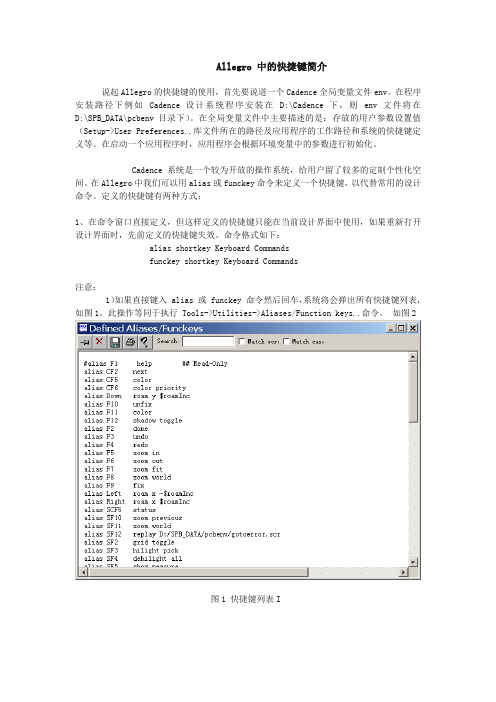
命令格式如下:alias shortkey Keyboard Commandsfunckey shortkey Keyboard Commands注意:1)如果直接键入 alias 或 funckey 命令然后回车,系统将会弹出所有快捷键列表,如图1。
此操作等同于执行 Tools->Utilities->Aliases/Function keys..命令。
如图2图1 快捷键列表I图2 快捷键列表II2)Allegro 中的所有键盘命令(Keyboard Commands)列表可以通过执行Tools->Utilities->Keyboard Commands 命令来查看,这些命令都可以设置成快捷键。
2、在env变量文件中直接定义,这样定义的命令将长期有效。
我们可以对它进行编辑。
我们的alias命令可以在第二行开始写(第一行是:source $ALLEGRO_INSTALL_DIR\text\env),快捷键的设定因个人习惯而设定,熟悉后方便快捷。
Allegro使用入门

Allegro 簡易使用說明1.Allegro知識介紹Allegro PCB軟體是美國Cadence公司的EDA軟體產品,並且大家熟悉的ORCAD也是該公司的產品。
目前PCB Layout的EDA工具大致有Protel,PCAD,Mentor graphics,POWER PCB和Allegro。
而Allegro PCB是全球在High-End PCB Layout系統市場中的領導者。
它對複雜;多層的PCB 設計提供良好且互動式的工作環境。
2.啟動程式1.啟動Allegro程式可以通過兩個途徑來實現:(1) 由開始功能表啟動:找到螢幕左下角的“開始”按鈕→向上移動到“程式集”功能表上,這時會自動跳出一欄子功能表→找到並把滑鼠移到Cedence PSD14.2上,又會出現下一級功能表→在裏面找到Allegro,移動滑鼠用左鍵點擊一下,Allegro就會自動開啟。
(如圖2-1);(2)在桌面建立一個快捷方式,每次啟動雙擊該圖示即可。
圖2-1啟動後會出現一個產品選擇對話方塊(Cadence Product Choices),我們選擇PCB Studio Performance,然後用左鍵單擊“OK”按鈕,這個時候Allegro就已經啟動了。
(圖2-2)圖2-21.開啟原有檔案:選擇File/Open會跳出一個OPEN對話方塊。
我們在“搜尋位置”的下拉功能表裏面找到想要打開的檔的路徑,找到檔後用滑鼠雙擊開啟。
(我們所操作的PCB檔為*.brd尾碼名稱)(圖2-3)圖2-33.工作視窗介紹在我們的Allegro工作視窗中可劃分為六個區域(圖3-1),分別為:1.指令區(menu bar) 2.圖示區(icon ribbon) 3.控制區(control panel) 4.工作區(design window) 5.狀態欄(status window) 6.命令區(console window)指令區:包含了Allegro中所有能夠用到的工具,命令和幫助資訊. 圖示區:將Allegro中常用的命令和工具以形象化的圖形表示出來,放在工作視窗內方便使用。
Allegro操作说明(中文)Word文档

Allegro操作说明(中⽂)Word⽂档26、⾮电⽓引脚零件的制作1、建圆形钻孔:(1)、parameter:没有电器属性(non-plated)(2)、layer:只需要设置顶层和底层的regular pad,中间层以及阻焊层和加焊层都是null。
注意:regular pad要⽐drill hole⼤⼀点27、Allegro建⽴电路板板框步骤:1、设置绘图区参数,包括单位,⼤⼩。
2、定义outline区域3、定义route keepin区域(可使⽤Z-copy操作)4、定义package keepin区域5、添加定位孔28、Allegro定义层叠结构对于最简单的四层板,只需要添加电源层和底层,步骤如下:1、Setup –> cross-section2、添加层,电源层和地层都要设置为plane,同时还要在电⽓层之间加⼊电介质,⼀般为FR-43、指定电源层和地层都为负⽚(negtive)4、设置完成可以再Visibility看到多出了两层:GND和POWER5、铺铜(可以放到布局后再做)6、z-copy –> find⾯板选shape(因为铺铜是shape)–> option⾯板的copy to class/subclass选择ETCH/GND(注意选择create dynamic shape)完成GND层覆铜7、相同的⽅法完成POWER层覆铜Allegro⽣成⽹表1、重新⽣成索引编号:tools –> annotate2、DRC检查:tools –> Design Rules Check,查看session log。
3、⽣成⽹表:tools –> create netlist,产⽣的⽹表会保存到allegro⽂件夹,可以看⼀下session log内容。
29、Allegro导⼊⽹表1、file –> import –> logic –> design entry CIS(这⾥有⼀些选项可以设置导⼊⽹表对当前设计的影响)2、选择⽹表路径,在allegro⽂件夹。
allegro的操作方式
allegro的操作方式Allegro是一款广受欢迎的电子商务平台,它提供了丰富多样的商品和服务供消费者选择。
在这篇文章中,我将介绍Allegro的操作方式,帮助读者更好地利用这个平台。
首先,要使用Allegro,我们需要在电脑或手机上下载并安装它的应用程序。
安装完成后,我们可以打开应用程序并注册一个账户。
注册过程非常简单,只需要提供一些基本的个人信息,如姓名、电子邮件和密码等。
注册成功后,我们就可以开始使用Allegro了。
在主界面上,我们可以看到各种商品的分类,如服装、家居、电子产品等。
我们可以根据自己的需求选择一个分类,然后浏览其中的商品。
当我们找到感兴趣的商品时,可以点击进入商品详情页面。
在这个页面上,我们可以看到商品的图片、描述、价格和卖家的评价等信息。
如果我们对这个商品感兴趣,可以点击“加入购物车”按钮将其添加到购物车中。
在购物车中,我们可以查看已选商品的列表和总价。
如果我们想继续购物,可以点击“继续购物”按钮返回主界面。
如果我们已经选择好了所有商品,可以点击“结算”按钮进入结算页面。
在结算页面上,我们需要填写收货地址和支付方式等信息。
Allegro支持多种支付方式,如信用卡、支付宝和微信支付等。
我们可以选择最方便的支付方式,并完成支付。
完成支付后,我们会收到一封订单确认的电子邮件。
同时,我们可以在Allegro的个人中心中查看订单的详细信息。
在个人中心中,我们还可以管理收货地址、查看购物历史和联系客服等。
除了购物功能,Allegro还提供了其他实用的功能。
例如,我们可以在搜索栏中输入关键词,快速找到我们想要的商品。
我们还可以设置关注某个商品,当它的价格发生变化时,会收到通知。
此外,Allegro还有一个社区功能,我们可以在社区中与其他用户交流和分享购物心得。
在社区中,我们可以发布帖子、评论和点赞等。
这个功能不仅可以帮助我们更好地了解商品,还可以结识志同道合的朋友。
总的来说,Allegro是一个功能强大、操作简便的电子商务平台。
Allegro16.5新增功能(中文版)
Allegro16.5新增功能(中文版)What’s New in Cadence OrCAD PCB Designer from 15.7 to 16.5Graser -JonathanTopicUIUsability Enhancements to Allegro Applications ?Constraints HDIx Icon 的更新,及工具群組的變更x 使工具視窗最大化GUI Modernization Cadence Branding New Icons Fold-Away Window TabsApplication Modes分為General,Etch,None….模式Quick access to popular forms or functionsEditing commands associated with selected elementHierarchical parent elementsUser controlsStatus Bar UpdatesFunctional responses forClass-subclassApp modesSuper filterNumber of selected objectsGeneral Edit Application Modes pre-selection編輯模式Central Location for Design Parameters新的參數設定界面包含Display, Design, Text, Etch Edit, Shape and manufacturingNew graphics engine支援OpenGL顯示OpenGL Enabled OpenGL DisabledQuick Access to Commonly Used Subclasses 自設常用的層面Highlighting with StipplesColor Dialog is enhanced tosupport 15 stipple patternsAssign color optionsHighlight optionsHighlighting with StipplesHighlighting of FixedNets/ComponentsDifferentiation of Keepout areasRatsnets Color Displayx使用不同顏色顯示不同層面的Ratx Display Option-Top:Top-Top:Bot-Bot:BotNet Element Coloring “Nets”Worksheet Added to Color DialogHighlight and Coloring“Assign Color”Function Integrated to Pre-Selection EnvironmentPin Number Displaypin number display with top and bottom layer visibilityFlip BoardFlip/Mirror boardabout Y axis ?Simple toggle on-offcommandFlip Mode indicator ?View and Full EditcapabilityOpen GL dependent3-D GraphicsOpen GL dependentSimple toggle On-Off command ?Full board view3-D GraphicsSupport multiple windowsView micro vias, through hole vias and traces on different layers ?Pre-selection supportView one net with HDI micro via breakout3-D GraphicsMouse driven Spin, Pan, Zoom functions ?Filtered View Options。
ALLEGRO16.6软件操作技巧
ALLEGRO16.6软件操作技巧2015/12/1A LLEGRO 16.6软件操作技巧----王颜飞文档内容仅供学习交流使用(部分资料来源网络)目录环境设置中的模板调用 (4)建立模板文件 (4)设置路径 (6)调用模板文件 (7)从Capture到Allegro通过第三方导入网表 (8)前期的设置与准备工作 (8)Capture导出第三方网络表 (9)在allegro中导入第三方网表 (9)Script录制的使用 (11)录制脚本 (11)录制设置 (11)回放脚本 (12)设置脚本录制配置路径 (13)设置快捷键回放脚本 (14)Parameter的使用 (15)导出Parameter (15)设置Parameter加载路径 (16)导入Parameter文件 (17)Techfile的使用 (18)导出techfile文件 (18)设置techfile文件加载路径 (19)导入techfile文件 (19)Color View Save 命令的使用 (20)设置需要显示的color views (20)保存color views (20)设置环境参数中color views配置路径 (21)如何使用color views (21)布局之Swap 命令(器件交换) (22)激活菜单命令 (22)交换对象 (22)右键菜单交换器件 (22)Swap Pin用法 (23)在原理图中设置Pin Group属性 (23) Allegro环境中交换引脚 (23)Swap Pin回注 (25)布局之模板复用 (27)布局布线其中一个模块; (27)创建复用模块 (27)调用模块 (29)模块复用完成 (31)Module Reuse用法 (32)原理图工程文件创建Module Reuse模块 (32) Allegro中创建Module Reuse模块 (33)设置软件的路径配置信息 (34)原理图工程中调用Module Reuse模块 (35) PCB 工程中调用Module Reuse模块 (36) Sub-Drawing用法 (38)导出Sub-Drawing (38)设置配置路径 (40)导入Sub-Drawing (40)如何在allegro中增加元件 (42)设置软件配置信息,允许logic编辑 (42)添加元件 (42)放置元件 (45)添加网络 (46)布局布线操作 (46)极坐标布局(来源阿杜) (48)环境设置中的模板调用实际应用中,为了节省设置环境的时间,我们就会根据需要建立的文件类型和实际情况制作模板。
allegro使用技巧
allegro使用技巧. allegro 使用技巧鼠标设定: 在ALLEGRO视窗LAYOUT时,每执行一个指令例:Add connect, Show element等鼠标会跳到Option窗口,这样对layout造成不便.1) 控制面版>滑鼠之移动选项中,指到预设按钮(或智慧型移动):取消“在对话方块将滑鼠指标移到预设按钮”设置2. Text path设置: 在ALLEGRO视窗LAYOUT时,不能执行一些指令:Show element,Tools>report…1) 应急办法:蒐寻一个相应的log文档copy到档案同一路径即可.2) Setup>User Preference之Design_Paths>textpath项设為:C:\cadance\PSD_14.1\share\pcb/text/views 即可.3. 不能编辑Net Logic.1) Setup>User Perference之项选择logic_edit_enabled,点选為允许编辑Net Logic, 默认為不能编辑Net Logic.4. 转gerber前需update DRC,应尽量将DRC排除,有些可忽略的DRC如何消除?1) logo中文字所產生的K/L error,可另外增加一个subclass,这样该文字不用写在ETCH层,可消除K/L error.2) 有些可忽略的P/P,P/L 的error,可给那些pin增加一个property---NO_DRC, 操作:Edit/Properties,选择需要的pin,选NO_DRC, Apply, OK5. 对某些PIN添加了”NO DRC”的属性可ERRO并不能消除﹐这是為什么?1) “NO DRC”属性只争对不同的网络﹐对相同的网络要清除ERRO,可设定Same net DRC 為off.6. 如何Add new subclass:1) Setup>Subclass之Define Subclass窗口选Class,点add”New subclass” 通常用到的new subclass有:Geometry\Board Geometry\之Top_notes, Bottom_notes, Gnd_notes, Vcc_notes等。
ALLEGRO使用教程

ALLEGRO使用教程一. PCB窗口介面介绍运行PCB EDIT 出现对话框注:不同的选项能实现的功能有所不同,一般P C B画板时选择A l l e g r o E x p e r t1.P C B介面2.工具栏其中工具栏的图标在相应的菜单栏中都可以找到,其对应关系如下:红色的文字对应菜单栏的选项。
如果工具栏图标太多或者太少,可以通过菜单View=>Customization=>Toolbar 自己增加或者减少一些不常用的图标3.控制栏说明控制栏主要有三大选择项:Option、Find 和Visibility通过控制面板的Option 标签可选择被激活的类或子类,在Allegro 数据库中,所有元素都有一个类属性(CLASS)或子类属性(SUBCLASS)。
通过控制面板的Find 标签,可以选择各种元素,如Nets、Lines、Vias等,当执行各种命令时,都需要在Find 标签中选择好相应的元素。
以移动命令为例,说明一下“Find”选项含义。
选择菜单Edit=>Move,再看“Find”选项如图所示,其中有多个复选框可供选择,想移动什么东西,一定要将其对应的复选框钩上“√”,比如,如果想要移动元件,首先点击一下“All Off”按钮,关闭所有的复选框,然后再将复选框“Symbols”钩上“√”,就可以对元件进行移动了。
如果要查看某个元件的信息,可以通过Display->Element,或单击图标,然后在Find 标签中选择好相应的元素。
通过控制面板的Visibility 标签,可以选择Etch 、Pin、Via、DRC 的各个子类的可视性。
“Visibility”下的“Views”可以用于快速切换窗口显示,其中的列表项内容是在进行过光绘的输出设置之后,就可以显示出来。
“Visibility”下的“layer”的意思就是对各层进行打开或者关闭显示,将小方框里打上“√”表示打开这层的显示,取消“√”表示不显示该层。
allegro使用简介

.scr
.art .log .color .jrl
Script 和macro 文件
输出的底片文件 输出的一些临时信息文件 View层面切换文件 纪录操作Allegro的事件
如何查看快捷键
2 弹出的文本框中可以看到 当前设计中所有的快捷方式
1 命令栏输入alias
如何自定义快捷方式
• 1 命令行中输入
– Format:alias [hotkey] [command] – Example: alias F9 rats all – Effect: 按F9键打开所有飞线 – Attention:此时定义的快捷键在环境变量中定义
– 在环境变量中找到HOME 的值 – 在HOME值指向的路径中 找到pcbenv文件夹 – 在env文件中编辑快捷方式, 格式同在命令行中编辑一 样,此时定义的快捷键不 仅仅局限于本次PCB编辑, 而是始终有效
一些常用的自定义配置
1 点击value 按钮 1 配置自己的Library路径,见右 图。树形图Paths\Library下每一 项都需要设置 2 将Display\Cursor\pcb_cursor 的value改为infinite可以实现同 PowerPCB一样的满屏大十字光 标 3 将Display\Visual\display_drcfill 的value勾选上可以将DRC标记设 置为实心的,方便观察 4 将Paths\Config\Scriptpath设置 为自己需要的路径 3 点OK 确认
查看线长2
• 开启constraints manageer
3 在这里可以看到实际的 trace长度
2 选择nettotal etch length
3 在需要查看的net上点右键 analyze
MAME街机模拟器常见问题与解答FAQ
MAME模拟器使用说明一、MAME常见问题与解答FAQ关于这个FAQ (4)A01. 为什么要出这个FAQ?A02. 如果我发现这个FAQ中有错误的地方那我该如何做呢?A03. 如果我想解决的问题在这个FAQ中找不到那我该怎么办?A04. 这个FAQ的是怎么来的?概要部份(10)G01. 什么是MAME呢?G02. 运行MAME我需要些什么?G03. 有没有Windows 95/98版本的MAME? 我可不可以用它来替代DOS版的?G04. 是不是有Amiga,Unix等系统的MAME模拟器?G05. MAME真的是完全免费的吗?G06. MAME是不合法的吗?G07. 我是否可以分发MAME和/或给我的朋友?G08. MAME是什么编的? 我可以得到源代码吗?G09. 迄今为止MAME都能模拟什么游戏了?G10. 嗨,模拟这个游戏和那个游戏!开始部分(12)S01. 我在哪儿可以得到MAME?S02. 我从哪里能得到MAME的(ROMs)呢?S03. 什么是声音Samples,我需要它干什么用,我在哪里可以得到它呢?S04. roms和声音Samples是ZIP (压缩)格式的。
我是否需要解压缩呢?S05. 一但我得到了游戏的ROMS我应该把它放在哪呢?S06. 我该把声音Samples文件放在哪里? MAME是怎么知道它在那儿的?S07. 我该如何执行MAME? (DOS和Win32)S08. 什么是CWSDPMI,我在哪能得到它,我该如何使用它?S09. 我不能解压缩MAME的压缩文件因为我没有任何解压缩程序。
S10. 什么是frontend?我需要吗? 假如这样的话我该使用哪个,我在哪里可以得到它?S11. 我如何确定自已获得了正确的ROMs?S12. 屏幕上奇怪的黑色水平线是怎么回事?我该如何...? (9)H01. 我该如何"按OK键"?H02. 好了,我已经在游戏的开始画面了。
allegro 遇到的问题汇总 避免忘记
allegro 遇到的问题汇总避免忘记allegro遇到的问题汇总避免忘记1、更新封装PCB修正后,在allegro之下palce--updatesymbols。
在packagesymbol之下挑选必须更新的PCB。
注意勾选updatesymbolpadstacksignorefixedproperty。
2、如何批量置放via?比方在top层铺了一片铜到地,然后想规则的放置一批via将表面铺铜区连接到地层,能不能自动完成啊?手动放很麻烦也不均与,影响美观copyfind勾xviaoption填上盗浚g距。
别人整理的还不错原文地址1.allegro中我设置了highlight的颜色为白色,但选上后颜色就是白蓝相间的,很不方便查阅。
就是什么地方须要设置,哪位大虾说哈我?请问:setup/userpreferences/display/display_nohilitefont这个选项打勾就行了。
2.不小心按了highlightsov后部分线高亮成白色,怎样取消?答:这个是用来检查跨分割的,取消的办法是:如果是4层板的话,在电源层跟地层都铺上地网络,然后再按highlightsov刷新即可。
3.如何修改highlight高亮预设颜色?答:可以在display->color/visibility->display->temporaryhighlight里修改即可,临时修改颜色可以点display->assigncolor来实现。
4.如实现highlight高亮部分网络,而背景变暗,就像altiumdesigner那样?请问:可以在display->color/visibility->display->shadowmode关上该模式,并且选上dimactivelayer即可。
5.快速切换层快捷键请问:可以按数字区里的“-”或“+”换得层。
答:orcad输出网表,allegro导入网表,确保两者对的上号,然后在orcad选中元件,再右键editorselect,即可在allegro中选中该元件;反过来,在allegro中要先highlight某元件,在orcad中变会选中该元件。
Allegro软件操作技巧
8
Allegro 软件操作技巧-lingling1350@
3) 开启 stroke 右键功能,并可在 toolsutilitiesstroke editor 中编 辑右键功能快捷键。
4) 非活动层阴影显示,设置好后在
切换。
17、script 录像机:filescript
9
Allegro 软件操作技巧-lingling1350@
在 Name 框里输入想要保存的文件名称,点击 Record 即可录制,然后去做想 做的动作,结束时再次执行 FileScript…点击 Stop 就 OK 了。 用这种方法可以把一些通用的操作录制保存下来,在新板中调出并回放,相 应的操作就自动搞定了。对于常用的操作,还可以把录制好的文件放的ENV目 录中,设置快捷键调用。 另外,还可以打开录制的脚本文件查看操作过程,可用于查看某个操作的名 字。 18、添加新的层面 SetupSubclasses,即出现以下左边对话框,选择想要建立的层 class 出现 以下右边对话框输入新建层名,回车,在显示框就可以看到所加的层了。 如果想删除某个层面,点击该层左边的 即可。注意只能删除用户自己 添加的层面。
5
Allegro 软件操作技巧-lingling1350@
2) (如上右图,其它操作同前) 3)上两步得到的网络列表分别拷到《U_管脚调整》表中。
再做成 lis 文件。
14、让两孔间的线等间距:ROUTE---RESIZE/RESPACE---SPREAD BETWEEN VOIDS。 对于两孔间有多跟线的情况同样适用。当然假如所有的线都用这种方法等间 距的话必然很费时, 修线时可以把格点改大、采用偶数小格点的方法就很容易让 两根线等间距了。 15、添加测试点 分为自动添加和手动添加两种,关键在于参数设置。 1) 自动添加
allegro软件常用功能操作技巧
allegro软件常用功能操作技巧allegro软件常用功能操作技巧汇总Allegro是Cadence推出的先进PCB 设计布线工具。
下面店铺准备了关于allegro软件常用功能操作技巧汇总的文章,提供给大家参考!1.在allegro中怎样移动元件的标识edit-->move,右边find面板只选text~~~2.allegro 查找元件的方法按F5 然后在Find 面板,Find by name 下面选Symbol(or pin) ,接着再下面输入元件名称,按回车后,屏幕就会高亮这个元件3.allegro 如何将元件元件到底层edit---mirror,find栏选SYMBOL和TEXT4.在Allegro中如何更改字体和大小(丝印,位号等)配置字体:allegro 15.2:setup->text sizestext blk:字体编号photo width: 配置线宽width,height:配置字体大小改变字体大小:edit->change,然后在右边控制面板find tab里只选text(只改变字体)然后在右边控制面板options tab里line width添线的宽度和text block里选字体的大小。
最后选你准备改变的TEXT。
框住要修改的所有TEXT可以批量修改allegro 16.0: setup->design->parameter->text->setup text sizetext blk:字体编号photo width: 配置线宽width,height:配置字体大小改变字体大小:edit->change,然后在右边控制面板find tab里只选text(只改变字体)然后在右边控制面板options tab里line width添线的宽度和text block里选字体的大小。
class->ref des->new sub class->silkscreen_top最后选你准备改变的TEXT,框住要修改的所有TEXT可以批量修改, 注意:如果修改顶层丝印要先关掉底部丝印层,silkscreen_bottom和display_bottom--------------------------------------------------------------------在建封装的时候可以设定5.如何allegro在中取消Package to Package Spacing的'DRC 检测setup -> constraint -> design constraints -> package to package ->off6.fanout by pick 的用途route->fanout by pick给bga自动的打via,对某个器件进行fanout,通俗的说就是从pin拉出一小段表层或底层线,打个孔7.No Placement Grid was found 的处理方法edit -> z-copy -> option->package keepin层 -> offset =40 或者 Setup -> Area -> Package KeepinROUTING KEEPIN 一般内移40MIL,PACK AGE KEEPING 一般内移120MIL8.在 PCB Editor 启动 Specctra的方法点击菜单 route ->route Editor 启动9.ERROR Unable to open property mapping file: devparam.txt.ERROR Unable to open property mapping file: devparam.txt.解决方法PSpice->Edit Simulation Profile-> Configuration Files->Library-> Library path->(toolspspicelibrary)下载全文。
Allegro 使用技巧总结

Allegro使用技巧总结 HJB编辑整理目录1.Allegro颜色设定,保存,调入和显示 (3)2.如何加入不同的via (3)3.如何让Allegro显示实心焊盘 (3)4.如何让Allegro与Concept-HDL实现反向标注 (3)5.如何使用FIX (3)6.如何使用Sub-Drawing (4)7.如何方便快捷的Placement (4)8.如何使用Auto Rename (4)9.如何只显示一部分飞线 (5)10.如何在不同的区域设置不同的规则 (5)11.如何更新pad、via (5)12.如何设置快捷键 (6)13.如何在Allegro中只显示连线,不显示同一层的铺铜 (6)14.倒角Manufacture-->Dimension/Draft-->Fillet (7)15.差分线的规则设置 (7)16.关于Export Techfile...和Import Techfile (7)17.Strokes的使用 (8)18.关于View-->Color View Save的使用 (10)19.edit-->vertex的使用 (10)20.器件、cline、via翻转、copy等问题的解决 (10)21.for padstack editor (10)22.如何导入DXF文件 (13)23.如何在Layout的时候动态的显示走线长度 (14)24.如何在ALLEGRO14.2中更改鼠标的"+"大小? (15)25.如何固定Allegro中菜单窗口的界面大小? (15)26.如何切换Allegro的新老版本?(含Bus走线功能简介) (15)27.Allegro中常见的文件格式 (16)28.关于做封装的步骤 (17)29.如何在Allegro中对器件厚度设定规则? (17)30.如何把边框的直角变成圆弧? (19)31.如何使用Dimension Datum标注尺寸? (19)32.如何能在打开Allegro时显示空白页? (20)33.关于表层铺铜Create Pin V oids (20)34.对于倾斜45度摆放的器件出Gerber的注意事项: (22)35.如何实现line和shape绘制的外框属性的转换 (22)1.Allegro颜色设定,保存,调入和显示1) 采用Script文件纪录板的设定(包括各层颜色)File-->Script...script这个命令是用来记录和调入操作用的。
Allegro菜单介绍

基础培训教程
Route(2)
Optimize Rat Ts:优化鼠线; Route Automatic:自动布线; Route Custom:用户自定义布线; Route Editor:登入Specctra自动布线器界面; Miter By Pick:选择性优化;90°转角转换为45°转角 UnMiter By Pick:取消优化; Spread Between Voids: Gloss:优化处理;删除多余VIA、多余Line、添加泪滴等
2012-10-17
一博科技 内部资料
9
基础培训教程
Display
Color/Visibility:设置颜色和显示; Color/Priority:设置优显颜色; Element:查看属性; Measure:测量距离; Property:查看带有某种属性的元素; Parasitic:显示阻抗、延迟等信息; Segments Over Voids:检查Net跨Plane; Highlight:反显(高亮); Dehighlight:取消反显; Waive DRCs:允许忽略DRC、隐藏DRC等; Show Rats:显示飞线 Blank Rats:隐藏飞线
2012-10-17
一博科技 内部资料
14
基础培训教程
Logic
Net logic:编辑Net的连接关系; Net Schedule:修改Net的逻辑路径; Assign Differential Pair:定义差分对; Identify DC nets:定义直流电压; Assign RefDes:编辑器件标号; Auto Rename Refdes:自动重命名器件标 号; Change Parts:器件型号转换 Part Logic:编辑器件逻辑关系 Terminator Assignment:终端分配
allegro使用基础知识汇总
注册登录EDA365返回首页日志主题:allegro基础知识汇总热度 2已有 279 次阅读2011-9-9 18:54|个人分类:allegro主题:allegro基础知识汇总1.如何在allegro中取消花焊盘(十字焊盘)set up->design parameter ->shape->edit global dynamic shape parameters->Thermal relief connects ->Thru pins ,Smd pins -> full contact2.allegro 中如何设置等长setup -> constraints->electrical->net->routing->Min Max Propagation delays选择要等长的net->右击->create->pin pair->选择pin修改 prop daly 的min 和max项3.如何设置allegro的快捷键修改文件 $inst_dir\share\pcb\text\env 或 $inst_dir\pcbevn\env快捷键定义如下:alias F12 zoom outalias ~R angle 90 (旋转90 度)alias ~F mirror (激活镜相命令)alias ~Z next (执行下一步命令)alias End redisplay(刷新屏幕)alias Del Delete(激活删除命令)alias Home Zoom fit(全屏显示)alias Insert Define grid(设置栅格)alias End redisplayalias Pgdown zoom outalias Pgup zoom inalias F12 custom smoothalias Pgup slidealias Pgdown donealias Home hilightalias End dehilightalias Insert add connectalias Del Delete4.如何在allegro中删除有过孔或布线的层时不影响其他层1.输出specctra的dsn文件allegro->file->export->router->demo.dsn->run2.产生session文件specctra(pcb router)->file->write->session->demo.ses->ok3.删除某一层中的布线和过孔delete(ctrl+D)->..4.删除allegro中的板层setup->cross section->鼠标右键->delete5.导入session文件allegro->file->import->router->demo.ses->run也可先将通过该层的过孔先替换成顶层焊盘,删除该层以后再替换回来5.如何在Allegro中同时旋转多个零件1.Edit->Move 在Options中Rotation的Point选User Pick2 再右键选Term Group 按住鼠标左键不放并拉一个框选中器件多余的可用Ctrl+鼠标左键点击去掉. 加为好友给我留言打个招呼发送消息xuexurongxuexurong的个人空间/?161350 [收藏] [复制] [分享] [RSS]3. 选好需整体旋转的器件后右键complete.4. 提示你Pick orgion 鼠标左键选旋转中心.5 下面右键选rotate 即可旋转了.6.allegro 16.0 透明度设置display->colour/visibility->display->OpenGL->Global transparency->transparent7.allegro Drill hole size is equal or larger than smallest pad size.Pad will be drilled away.提示Drill hole size is equal or larger than smallest pad size.Pad will be drilled away.不用理睬这一提示8.ALLEGRO 如何生成钻孔文件Manufacture -> NC -> Drill Customization->auto generate symbolsManufacture -> NC -> Drill LegendManufacture -> NC ->NC parameters->enhanced excellon format->closeManufacture -> NC -> NC Drill->auto tool select->optimize drill head travel9.CAM350如何正确导入钻带文件导进去后MACRO->PLAY->选择(CAM350--SCRIPTS)PADS_DRILL->选择钻带的REP文件还没测试过,rep文件从哪儿来的呢10.allegro 如何设置route keepin,package keepin1.setup->area->route keepin,package keepin ->画框2.edit ->z-copy->options->package keepin,route keepin->offset->50->点击外框11.allegro 中如何禁止显示shape完全禁止的方法没找到setup->user preference editor->display->display_shapefill->输入一个较大的数shape在显示时就不是那么显眼了set-user preference editor-shape-no shape fill(v)12.如何在allegro设置自定义元件库路径在下面两个位置添加自定义元件的路径Setup->User Preferences Editor->Design_paths->padpathSetup->User Preferences Editor->Design_paths->psmpath1.在allegro中如何修改线宽在Allegro的Setup->constraints里的set standard values中可定义每一层走线的宽度,比如,可以定义VCC和GND的线宽为10 Mil。
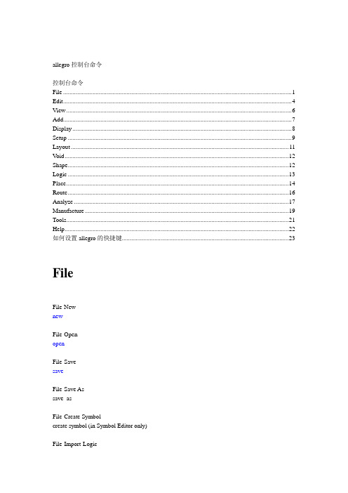
Allegro的控制台命令使用介绍,很详细的
allegro控制台命令控制台命令File (1)Edit (4)View (6)Add (7)Display (8)Setup (9)Layout (11)V oid (12)Shape (12)Logic (13)Place (14)Route (16)Analyze (17)Manufacture (19)Tools (21)Help (22)如何设置allegro的快捷键 (23)FileFile-NewnewFile-OpenopenFile-SavesaveFile-Save Assave_asFile-Create Symbolcreate symbol (in Symbol Editor only)File-Import-Logicnetin paramFile-Import-Artwork load photoplotFile-Import-Streamload streamFile-Import-IPFload plotFile-Import-DXFdxf inFile-Import-IDFidf inFile-Import- IFFiff inFile-Import-SPECCTRA specctra inFile-Import-Redac redac inFile-Import-Visula visula inFile-Import-PADSpads inFile-Import-PCADpcad inFile-Import-Sub-Drawing clppasteFile-Import-Techfile techfile inFile-Import-Active Times signal atimesFile-Import-Placementplctxt inFile-Annotationsannotation inFile-Export-LogicfeedbackFile-Export-Netlist w/Properties netoutFile-Export-IPFcreate plotFile-Export-DXFdxf outFile-Export-IDFidf outFile-Export-SPECCTRA specctra_outFile-Export-Sub-Drawing clpcopyFile-Export-LibrariesdlibFile-Export-Techfiletechfile outFile-Export-Placementplctxt outFile-Export-Annotations annotation outFile-Export-IPC 356ipc356 outFile-Export-Valor ODB ++ inside odb_outFile-Export-Save design to 14.0 downrevFile-ViewlogviewlogFile-File ViewerNo corresponding commandFile-Plot Setupplot setupFile-Plot Preview (Windows NT only) plot previewFile-PlotplotFile-Propertiesfile_propertyFile-Change EditortoolswapFile-ScriptscriptFile-ExitexitEditEdit-MovemoveEdit-CopycopyEdit-MirrormirrorEdit-SpinspinEdit-ChangechangeEdit-DeletedeleteEdit-Shapeshape editEdit-Z-Copyzcopy shapeEdit-Delete Unconnected Shapes delete unconnectedEdit-Split Plane-Parameters split plane paramsEdit-Split Plane-Createsplit plane createEdit-Split Plane-Locate Islands locate islandsEdit-Compose Shape compose shapeEdit-Decompose Shape decompose shapeEdit-VertexvertexEdit-Delete Vertexdelete vertexEdit-Boundary (Shape editor only) boundaryEdit-Change Net (Pick) (Shape editor only) changenet pickEdit-Change Net (Name) (Shape editor only) changenet nameEdit-Texttext editEdit-Chamfer (in Designer and Studio series) draft chamferEdit-Fillet (in Designer and Studio series) draft filletEdit-GroupsgroupeditEdit-Propertiesproperty editViewView-Zoom By Pointszoom pointsView-Zoom Fitzoom fitView-Zoom Inzoom inView-Zoom Outzoom outView-Zoom Worldzoom centerView-Zoom Centerzoom centerView-Zoom Previouszoom previousView-Color View Save colorview createView-Color View Restore Last colorview restoreView-RefreshNo corresponding commandView-Customization-Display display paramView-Customization-Toolbar No corresponding commandAddAdd-Lineadd lineAdd-Arc w/Radiusadd rarcAdd-3pt Arcadd arcAdd-Circleadd circleAdd-Rectangleadd rectAdd-Frectangleadd frectAdd-Textadd textAdd-Shapes-Solid Filladd fshapeAdd-Shapes-Unfilledadd ufshapeAdd-Shapes-Cross Hatch Fill add xshapeDisplayDisplay-Color/Visibility colorDisplay-Color Prioritycolor priorityDisplay-Elementshow elementDisplay-Measureshow measureDisplay-Parasiticshow parasiticDisplay-Propertyshow propertyDisplay-HighlighthilightDisplay-DehighlightdehilightDisplay-Show Rats-Allrats allDisplay-Show Rats-Components rats componentDisplay-Show Rats-Netrats netDisplay-Blank Rats-Allunrats allDisplay-Blank Rats-Components unrats componentDisplay-Blank Rats-Nets unrats netSetupSetup-Drawing Sizedrawing paramSetup-Drawing OptionsstatusSetup-Text Sizesdefine textSetup-Gridsdefine gridSetup-Subclassesdefine subclassSetup-Cross-sectiondefine xsectionSetup-Vias-Define B/B Viadefine bbviaSetup-Vias-Auto Define B/B Viaauto define bbviaSetup-ConstraintscnsSetup-Electrical Constraint Spreadsheet cmgrSetup-Property Definitionsdefine propertySetup-Define Listsdefine listSetup-Areas-Package Keepinkeepin packageSetup-Areas-Package Keepout keepout packageSetup-Areas-Package Height package_heightSetup-Areas-Route Keepinkeepin routerSetup-Areas-Route Keepoutkeepout routerSetup-Areas-Via KeepoutSetup-Areas-Probe Keepoutkeepout probeSetup-Areas-Gloss Keepoutkeepout glossSetup-Areas-Photoplot Outlinekeepin photoSetup-User Preferencesenv editorLayoutLayout menu selections are available only in the Symbol EditorLayout-Pinsadd pinLayout-Connectionsadd connectLayout-SlideslideLayout-Labels-RefDeslabel refdesLayout-Labels-Devicelabel deviceLayout-Labels-Valuelabel valueLayout-Labels-ToleranceLayout-Labels-Part Numberlabel partVoidV oid menu selections are available only in the Shape EditorV oid-Shapevoid shapeV oid-Circlevoid circleV oid-Elementvoid elementV oid-Autovoid allShapeShape menu selections are available only in the Shape EditorShape-Parametersshape paramShape-Checkshape checkShape-Fillshape fillLogicLogic-Net Logicnet logicLogic-Net Schedulenet scheduleLogic-Assign Differential Pairdiff pairsLogic-Identify DC Netsidentify netsLogic-Assign RefDesassign refdesLogic-Auto Rename RefDes-Rename rename paramLogic-Auto Rename RefDes-Design rename area designLogic-Auto Rename RefDes-Room rename area roomLogic-Auto Rename RefDes-Window rename area windowLogic-Auto Rename RefDes-List rename area listLogic-Change PartsparteditLogic-Terminator Assignment ecl paramPlacePlace-Manuallyplace manualPlace-Quickplace quickplacePlace-SPECCTRAspecctraPlace-Autoplace-Insight place insightPlace-Autoplace-Parameters place paramPlace-Autoplace-Top Grids place set topgridPlace-Autoplace-Bottom Grids place set bottomgridPlace-Autoplace-Design place area designPlace-Autoplace-Roomplace area roomPlace-Autoplace-Window place area windowPlace-Autoplace-List place area listPlace-Interactiveplace interactivePlace-Swap-Pinsswap pinsPlace-Swap-Functions swap functionsPlace-Swap-Components swap componentsPlace-Autoswap-Parameters swap paramPlace-Autoswap-Design swap area designPlace-Autoswap-Room swap area roomPlace-Autoswap-Window swap area windowPlace-Autoswap-List swap area listPlace-Evaluate-Parameters eval paramPlace-Evaluate-Design eval area designPlace-Evaluate-Roomeval area roomPlace-Evaluate-Window eval area windowPlace-Evaluate-Listeval area listPlace-Update Symbolsrefresh symbolPlace-Replace SQ Temporary-Devices replace temp_devicePlace-Replace SQ Temporary-Symbols replace temp_symbolsRouteRoute-Connectadd connectRoute-SlideslideRoute-Custom Smoothcustom smoothRoute-SPECCTRA-Run Router Checks specctra checksRoute-SPECCTRA-Route by Pick route_by_pickRoute-SPECCTRA-Route Automatic auto_routeRoute-SPECCTRA-Interactive Editor specctraRoute-Gloss-Parametersgloss paramRoute-Gloss-Designgloss area designRoute-Gloss-Roomgloss area roomRoute-Gloss-Windowgloss area windowRoute-Gloss-HighlightNo corresponding commandRoute-Gloss-Listgloss area listRoute-Testprep-Auto testpreop paramRoute-Testprep-Create Probe probe createRoute-Testprep-Delete Probe probe deleteRoute-Testprep-Swap Probe probe swapRoute-Testprep-NC Tape Probes nctapeAnalyzeAnalyze-SI/EMI Sim-Initialize signal initAnalyze-SI/EMI Sim-Library signal libraryAnalyze-SI/EMI Sim-Modelsignal modelAnalyze-SI/EMI Sim-Model Dump/Refresh signal model refreshAnalyze-SI/EMI Sim-Preferencessignal prefsAnalyze-SI/EMI Sim-Audit-Design Auditsignal auditAnalyze-SI/EMI Sim-Audit-Net Auditsignal audit netAnalyze-SI/EMI Sim-Audit-Audit One Librarysignal lib auditAnalyze-SI/EMI Sim-Audit-Audit List of Librariessignal libs auditAnalyze-SI/EMI Sim-Probesignal probeAnalyze-SI/EMI Sim-Xtalk Tablesignal xtalktableAnalyze-EMI Rules-Initializesignal eminitAnalyze-EMI Rules-Auto Setupsignal emiautopropmainAnalyze-EMI Rules-Manual Setupsignal emimanualpropmainAnalyze-EMI Rules-Rule Selectsignal emiruleselectAnalyze-EMI Rules-Auditsignal emiverifyAnalyze-EMI Rules-Executesignal emiexecuteAnalyze-EMI Rules-Resultssignal emiresultsAnalyze-EMI Rules-Audit Reportsignal emiverifyreportAnalyze-EMI Rules-Execute Reportsignal emiexecutereportManufactureManufacture-Dimension/Draft commands in the Layout Editor are accessed under the Dimension menu item in the Symbol EditorManufacture-Dimension/Draft-Parametersdraft paramManufacture-Dimension/Draft-LineFontlinefontManufacture-Dimension/Draft-Linear Dimdimension linearManufacture-Dimension/Draft-Datum Dimdimension datumManufacture-Dimension/Draft-Angular Dimdimension angularManufacture-Dimension/Draft-Leader Linesleader onlyManufacture-Dimension/Draft-Diametral Leaderleader diametralManufacture-Dimension/Draft-Radial Leader leader radialManufacture-Dimension/Draft-Balloon Leaderleader balloonManufacture-Dimension/Draft-Chamfer Leaderleader chamferManufacture-Dimension/Draft-Chamfer draft chamferManufacture-Dimension/Draft-Filletdraft filletManufacture-Dimension/Draft-Create Detail create detailManufacture-Artworkfilm paramManufacture-Stream Outstream outManufacture-NC-Drill Parametersncdrill paramManufacture-NC-Drill Legendncdrill legendManufacture-NC-Drill Tapenctape_fullManufacture-NC-RoutencrouteManufacture-Cut Markscut marksManufacture-DFA CheckdfaManufacture-Create Couponscreate couponsManufacture-Silkscreensilkscreen paramManufacture-Variants-Create Assembly Drawing variant assemblyManufacture-Variants-Create Bill of Materials variant bomToolsTools-Create Modulecreate moduleTools-Padstack-Modify Design Padstack padeditdbTools-Padstack-Modify Library Padstack padeditlibTools-Padstack-Replacereplace padstackTools-Padstack-Group EditmultpadeditTools-Padstack-Refreshrefresh padstackTools-Pad-Boundaryeditpad boundaryTools-Pad-Restoreeditpad restoreTools-Pad-Restore ALL editpad restore allTools-Silkscreensilkscreen paramTools-Derive Connectivity derive connectivityTools-ReportsreportsTools-Technology File Compare techfile compareTools-Setup Advisorsetup advisorTools-Database Check dbcheckTools-Update DRCdrc updateHelpHelp-Allegro HelphelpHelp-Product NotesNo corresponding commandHelp-Known Problems and SolutionsNo corresponding commandHelp-Web Resources-SourcelinkNo corresponding commandHelp-Web Resources-EducationNo corresponding commandHelp-Web No corresponding commandHelp-ManualscdsdocHelp-Design FlowNo corresponding commandHelp-About AllegroNo corresponding command如何设置allegro的快捷键2010-01-24 00:21如何设置allegro的快捷键(ZT)修改变量文件,设置自定义快捷键。
- 1、下载文档前请自行甄别文档内容的完整性,平台不提供额外的编辑、内容补充、找答案等附加服务。
- 2、"仅部分预览"的文档,不可在线预览部分如存在完整性等问题,可反馈申请退款(可完整预览的文档不适用该条件!)。
- 3、如文档侵犯您的权益,请联系客服反馈,我们会尽快为您处理(人工客服工作时间:9:00-18:30)。
14
2012 Cadence Design Systems - All Rights Reserved
Thermal Alignment- Xhatch shapes
13
2012 Cadence Design Systems - All Rights Reserved
Add Circle Enhancements
• The following ease of use updates were made to commands associated with adding a circle.
SPB 16.6 AE Training – PCB Editor
September 2012 Ed Hickey Ed Acheson
Topics
Overview Module 1: Productivity Features Module 2: Route Interconnect Optimization (RIO) Module 3: DFM, Database, Interfaces Module 4: Team Design Module 5: Embedded Component Design
2
2012 Cadence Design Systems - All Rights Reserved
Workshop Overview
3
2012 Cadence Design Systems - All Rights Reserved
Contents of Workshop Kit
• Workshop doc • What’s new presentation • Board files • Symbol library • Tips & Tricks Workshop
• Session 2 (4 hours)
– – – – – DFM Database Interfaces Team Design Embedded Component
5
2012 Cadence Design Systems - All Rights Reserved
T2 Cadence Design Systems - All Rights Reserved
Shape Expansion/Contraction
• The ability to contract or expand an existing shape(s) is available in General Edit Application mode. • Pre-select one or more shapes then use RMB context sensitive menu to access the Expand/Contract command. • Use +/- buttons in combination with the value field to incrementally change the shape size.
15
2012 Cadence Design Systems - All Rights Reserved
Embedded Net Names
• New display option overlays net names within …
– – – – Clines Pins Shapes Flow Lines
• A new dynamic shape option aligns thermal spoke widths used for cross hatch shape applications to that of the line widths used for the actual shape hatching. • Normally the thermal line width is controlled by the ‘min line width’ property associated with the net. If the property value changes, the thermal width would be updated. • A Flex PCB Designer can now set this option and maintain the integrity of the copper hatched region regardless of line width updates forced by the schematic or property overrides.
• Display setting located in Design Parameters – Display Folder
– Enabled by default – Requires Open GL
– Equal spacing between components – Use DFA spacing for min compression – Increment/Decrement controls to adjust spacing during dynamics
Before alignment
– We will support the Windows 8 64bit Intel based version – Windows RT (ARM) and Windows 7 32bit Intel will NOT be supported – It will be supported by a future SPB release. The SPB version and our support date has not be finalized – We will not support Windows 8 with SBP 16.5 or older releases
• Aligned with “Place Rectangle” option
– Corner style options
• Orthogonal (default) • Chamfer • Round
– Corner length options
• Trim or chamfer length • As a percent of the shorter edge
6
2012 Cadence Design Systems - All Rights Reserved
Productivity Enhancements
7
2012 Cadence Design Systems - All Rights Reserved
Component Alignment
• Introduced in 16.3
– Relevant commands include Add Circle, Shape Circular and Shape Manual Void Circular.
• Circle creation options: – Draw Circle – mouse guided circle creation – Place Circle – user guided placement of parameterized circle – Center / Radius – place parameterized circle at x,y coordinate • Use General Edit Application mode to easily change the radius of an instantiated line drawn circle.
9
2012 Cadence Design Systems - All Rights Reserved
Quickplace Overlap Controls
• A new control option, ‘overlap components by’ is introduced to improve completion percentages. • The user can control the amount of overlap; the default value is seeded at 50%.
– Placement App Mode
• Enhanced in 16.6 to support
– Alignment Edge of component
• Bottom or Top if aligned Horizontally • Left or Right if aligned Vertically • Placebound shape used as alignment object
4
2012 Cadence Design Systems - All Rights Reserved
Core Allegro
• Split into 2 sessions • Session 1 (5 hours)
– Productivity Features – Route Interconnect Optimization (RIO)
• Quiz - 5 questions from each session • Customer Distribution – generally OK to distribute this workshop but wait for an update as there are always minor corrections to make after WW training • Windows 8
