倍加福K系列安全栅系统手册K-System Isolated Barriers
倍加福KCD2-UT2-EX1安全栅参数及接线说明

KCD2-UT2-EX1安全栅参数及接线方式
特征:
•1-通道隔离屏障
•24 V直流电源(电源轨)
•热电偶,RTD,电位器或电压输入
•电流输出0/4 mA…20mA
•接收或源模式
•可由PACTware配置
•线路故障(LFD)和传感器烧毁检测
•最高SIL 2 acc。
至iec61508 / iec61511
外部结构图
这个隔离的屏障用于内在安全应用。
该设备转换RTD输入信号或热电偶输入危险区域信号为0/4 mA…20mA信号安全区域。
可移动终端块KC-CJC-**可用热电偶内部冷端补偿
故障由LED和用户配置的故障指示显示输出。
如果设备是通过电源线操作的,另外集体错误消息是可用的。
使用PACTware可以很容易地配置该设备。
美国优倍 安全栅样本及技术手册
单/双通道电压输入,单/双路输出··········································14
单/双通道开关量输入,开关量输出·········································16
检测端(输入端)安全栅
单/双通道热电偶输入,单/双路输出··········································6
单/双通道热电阻输入,单/双路输出··········································8
单/双通道二、三线制电流输入(配电功能),单/双路输出·································10
安全栅的基本知识···········································首页
安全栅的基本知识·············································1
安全栅通用技术指标············································5
中国国家防爆电气产品质量监督检验中心是中华人民共和国地区监督生产安全防爆产品的权威机构,对本安型安全栅产品有着严格、科学、详细的规定,只有通过该监督站认证的企业及其所开发生产的产品才具备符合标准的安全性能,否则可能会给使用方的设备、人员和生产造成无可估量的损害。
术语解释:
关联设备
一种安装在安全场所,本安电气设备与非本安电气设备之间的相连的电气设备。
输入信号故障输出方式及指示设定·····································34
美国优倍 安全栅样本及技术手册

supplied with delivery should be finally applied.
Tte series of product and management systems have passed the following certifications or tests:
优倍电气总部位于南京市中心,南京优倍为优倍电气在亚洲地区最高的管理机构。优倍电气在中国各地区共有研发、生产、管理、商务等各类人员近200名,机构遍布南京、北京、沈阳、哈尔滨、上海、广州、成都、重庆等地,总部位于南京市中央商务区,工业园位于南京六合经济技术开发区,园区占地面积20亩,厂房、办公大楼、休闲区等设施齐全,并有EMC试验仪、大型全自动SMT无铅化回流焊、福碌克自动校验系统等多套先进的设备。
南京优倍为中石化一级供应商,具有向中国所有石化企业供货的资质,并通过中国船级社CCS产品认证,并已成为西门子、霍尼韦尔等诸多国际著名公司的配套供货方。产品广泛应用于石油、化工、冶金、电力、水泥、造船等行业。
自2002年南京工厂投产以来,年产量已逐年递增至近10万台件,累计产量已达40万台件,是中国地区最具规模的专业的前级仪表研发制造的企业之一。南京优倍已以迅猛发展的速度成为同行中的佼佼者,优倍品牌产品已经成为国际仪表行业的主流品牌之一。
检测端(输入端)安全栅
单/双通道热电偶输入,单/双路输出··········································6
单/双通道热电阻输入,单/双路输出··········································8
P+F安全栅说明书(中文)

KF系列隔离栅应用指南PEPPERL + FUCHSKF系列隔离式安全栅隔离式安全栅限制回路电能量从而实现本质安全防爆功能的回路限能关联设备通常被称为安全栅。
而带有电流隔离功能的安全栅,则被称为隔离式安全栅,简称隔离栅。
隔离栅通常由回路限能单元、电流隔离单元和信号处理单元三部分组成,如图1所示。
回路限能单元中最核心的电路为安全栅基本限能电路。
此外,辅助有用于驱动现场仪表的回路供电电路和用于仪表信号采集的检测电路。
电流隔离单元包括变压器隔离组件、模频转换和频模转换电路。
信号处理单元则根据各品种隔离栅的功能要求实施信号处理。
为什么选用隔离栅齐纳式安全栅(详见齐纳式安全栅的章节)和隔离式安全栅都能实现本质安全防爆的功能。
与简单廉价的齐纳栅相比,隔离栅会给用户带来哪些利益呢?1. 隔离栅可将危险区的现场回路与主控室安全区的控制系统有效隔离。
这种隔离可同时带来三大好处:其一,隔离栅无需本安接地。
简化了本安防爆应用时的工程施工。
其二,大大增强了检测和控制回路的抗干扰能力。
其三,允许现场仪表接地,且现场仪表接地将不会与控制系统接地之间产生相互影响。
2. 应用隔离栅可缩短开车准备时间和减少停车时间。
这是因为隔离栅具有比齐纳栅强得多的自我保护能力,意外损坏的可能性较小。
同时,隔离栅允许现场仪表带电检修,从而减少了停车。
3. 隔离栅具有较强的信号处理功能,给现场仪表和控制系统的应用提供了更大的选择空间。
从而使整个系统的配置更合理和有效。
4. 当用户同时应用DCS和ESD时,选用一进二出的隔离栅,可以有效地将两个系统隔离开来。
从而避免一个系统的故障影响另一个系统。
P+F公司有哪几个系列的隔离栅 P+F公司已有40年研发和生产隔离栅的经验。
现共有4个系列的隔离栅畅销世界各地。
1. KF系列隔离栅。
这是销售量最大、应用最广泛的隔离栅系列。
本样本将详细介绍。
2. KS系列远程I/O型隔离栅。
这是最新型的隔离栅系列。
它在隔离栅基础上又集成了远程I/O的功能。
开关量隔离安全栅说明书

环境温度
0~50℃
环境湿度
5%~95%RH(非结露)
外形尺寸
18.5*109*116.5mm(宽*高*深)
标准
电磁兼容性
符合GB/T18268工业设备应用要求
4 接线图
危险区
安全区
7 8 In1
1(S +) Out1
2(S -)
+ DC24V _
5
6
危险区
安全区
7 8 In1
10 In2
11
1(S +) Out1 2(S -)
2 选型表
开关量输入检测端隔离栅
位 规格
7/8
<输入类型>
输入I/输入II(从列表中选择代码)
代码
类型
X
无输入
36
开关量
9/10
倍加福安全栅KCD2-UT2-EX1信号转换安全栅导轨式技术参数介绍

倍加福安全栅KCD2-UT2-EX1信号转换安全栅导轨式技术参数介绍倍加福安全栅KCD2-UT2-EX1信号转换安全栅导轨式技术参数介绍KCD2-UT2-Ex1通用温度转换器1通道隔离屏障,24v直流电源(电源轨道),热电偶,RTD,电位器或电压输入,电流输出0/4ma…20ma,接收器或源模式,可由PACTware配置,线路故障(LFD)和传感器燃尽检测,SIL 2 acc。
符合IEC/EN 61508 / IEC/EN 61511标准,外壳宽度:12.5 mm,通道数:1通道,安全完整性等级(SIL): SIL 2,额定电压:19…30v DC,型号:2线连接,[2]型:3线连接,[3]型:4线连接输出连接端控制端连接端子5:源端(-),端子6:源端(+),端子7:汇聚端(-),端子8:汇聚端(+)模拟电流输出当前范围0…20ma或4…20马故障信号下行0或2ma,上行21.5 mA (acc。
那慕尔NE43)源负载0…550Ω开路电压≤18v接收端子电压5…30 V。
如果电流来自一个电源>16.5 V,串联电阻≥(V - 16.5)/0.0215 Ω,其中V为源电压。
电阻的*值为(V - 5)/0.0215 Ω。
传输特性偏差校准后pt100:±(K测量值的0.06% +跨度的0.1% + 0.1 K(4线连接))热电偶:±(°C测量值的0.05% +跨度的0.1% + 1.5 K (R型和S型为1.7 K)),包括冷结补偿(CJC)的±1.3 K故障mV:±(50µV + 0.1 %量程)电位器:±(满量程0.05% +量程0.1%,(不包括引线电阻引起的故障))环境温度pt100的影响:±(测量值在K的0.0015% +跨度的0.006%)/K ΔTamb*)热电偶:±(0.02 K + 0.005%的测量值在°C + 0.006%的跨度)/K ΔTamb*)),包括冷结补偿(CJC)的影响mV:±(测量值的0.01% +跨度的0.006%)/K ΔTamb*)电位器:±0.006%跨度/K ΔTamb*)*) ΔTamb =环境温度变化参考23°C (296 K)电源电压及lt的影响;跨度0.01%负载影响≤每100输出值的0.001%反应时间*坏情况值(启用传感器破损和/或传感器短路检测)mV: 1s, CJC热电偶:1.1 s,固定参考温度热电偶:1.1 s, 3线或4线RTD: 920 ms, 2线RTD: 800 ms,电位器:2.05 s电隔离输出/供应,编程输入功能绝缘,额定绝缘电压50v AC在编程输入和电源之间没有电气隔离。
P F倍加福安全栅分类使用原理及选用

P+F倍加福安全栅分类使用原理及选用行业工程师与大家分享P+F倍加福倍加福安全栅分类使用原理。
如何选择P+F倍加福倍加福安全栅,使用P+F倍加福倍加福安全栅时应该注意哪些事项,P+F倍加福安全栅安装注意事项,P+F倍加福倍加福安全栅如何维护?东莞市巴菲特专业为您提供P+F倍加福倍加福安全栅相关问题解答。
除了要选择合适的安全栅外,使用P+F倍加福安全栅的时候要注意以下几个方面:第一,要注意线缆和现场设备的容抗和感抗,本安防爆是系统防爆,除了安全栅需要达到所需的防爆等级外,线缆和现场设备的蓄能也是一个关键问题。
特别是在参量认证替代系统认证后,工程商尤其要注意这个问题。
第二,要注意本安接地,齐纳安全栅需要本安接地,接地电阻应小于1。
第三,本安线缆与非本安线缆应分开敷设在不同的线槽里。
并应有明显标识。
第四,更换时应注意断电。
倍加福安全栅又称安全限能器,是本安系统中的重要组成部分。
倍加福安全栅主要有P+F齐纳式安全栅和P+f隔离式安全栅两大类。
倍加福齐纳式安全栅的核心元件为齐纳二极管,限流电阻及快速熔断丝。
P+f隔离式安全栅信号和电源隔离单元、信号处理单元组成。
倍加福安全栅的主要功能为限流限压,保证现场仪表可得到的能量在安全范围内。
倍加福安全栅是介于现场设备与控制室设备之间的一个限能电路,用来把控制室供给现场仪表的电能量限制在既不能产生足以引爆危险气体的火花,又不能产生足以引爆危险气体的仪表表面温度,从而消除了引爆源。
在选择倍加福安全栅时必须考虑其型号与现场仪表类型相适应,还须考虑倍加福安全栅与本质安全仪表要求相兼容及形成的本安系统中阻抗匹配的问题。
我国采用“回路认证”这种方式认证本安系统,即根据危险环境使用仪表的联合取证情况,选择已与其联合取证的倍加福安全栅,一经联合取证,现场仪表与倍加福安全栅便固定组合构成本安系统。
实践中,这种方式对倍加福安全栅和现场仪表的选择有很大的局限性。
广泛采用是进年来逐渐形成的一种本质安全认证技术,即“参量认证”。
P+F安全栅说明书(中文)

KF 系列隔离栅致力与在完成本安防爆的 基本功能的同时,帮助用户获得更多的信息。 • 全面支持模拟量输入输出回路的智能通讯。该
系列隔离栅支持目前市场上应用的所有智能通 讯协议,如 HART、Brain、Foxcom、DE, 等等。 • 在支持 HART 智能通讯方面,KF 系列隔离栅 设计得几乎无微不至。不仅普通的单通道 AI 和 AO 型号支持 HART,双通道 AI 和 AO、一 进二出 AI 同样支持 HART。不仅支持二线制 変送器的 HART 通讯,还支持 4 线制変送器 的 HART 通讯。 • KF 系列隔离栅还细致地照顾到用户在全面应 用智能通讯时地一些特殊问题。比如,用户有 时希望支持 HART 通讯地隔离栅能兼容非智 能仪表。又如,用户希望在 DCS 系统尚未连
有源或无源 4-20mA 信号,或 1-5V 信号。
单通道 是 SIL2 有源 4-20mA 信号。智能型,
双通道 是 SIL2 支持 HART。
一进二出 是 SIL2
KFD2-STC4-Ex1-Y122583 单通道 是 SIL2 无源 4-20mA 信号。智能型,
KFD2-STC4-Ex1.2O-Y122582 一进二出 是 SIL2 支持 HART。
AO,
KCD2-SCD-Ex1
单通道 是 SIL2 4-20mA 信号。兼容智能/非智
4-20mA 驱动电气转 换器或电气 阀门定位器
KFD2-SCD-Ex1.LK KFD2-SCD2-Ex2.LK KFD2-CD-Ex1.32 KFD2-CD2-Ex2
单通道 双通道 单通道 双通道
是 SIL2 能仪表。带线路故障检测功 是 SIL2 能。 否 SIL2 4-20mA 信号。 否 SIL2 4-20mA 信号。
Pepperl+Fuchs KFD2-SCD2-Ex1.LK产品说明书
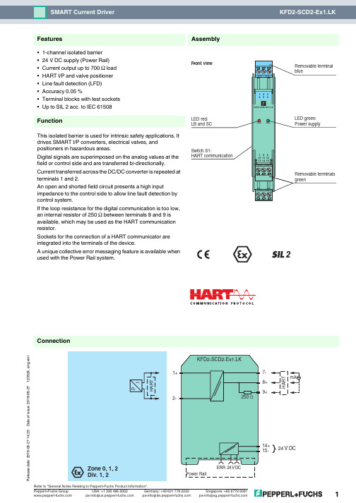
19-06-27 14:25D a t e o f i s s u e 2019-06-27123524_e n g .x m l2-1+7-8+9+24 V DC14+15-ConnectionAssembly•1-channel isolated barrier •24 V DC supply (Power Rail)•Current output up to 700Ω load •HART I/P and valve positioner •Line fault detection (LFD)•Accuracy 0.05 %•Terminal blocks with test sockets •Up to SIL 2 acc.to IEC 61508FunctionThis isolated barrier is used for intrinsic safety applications. It drives SMART I/P converters, electrical valves, and positioners in hazardous areas.Digital signals are superimposed on the analog values at the field or control side and are transferred bi-directionally.Current transferred across the DC/DC converter is repeated at terminals 1 and 2.An open and shorted field circuit presents a high inputimpedance to the control side to allow line fault detection by control system.If the loop resistance for the digital communication is too low, an internal resistor of 250Ω between terminals 8 and 9 is available, which may be used as the HART communication resistor.Sockets for the connection of a HART communicator are integrated into the terminals of the device.A unique collective error messaging feature is available when used with the Power Rail system.2Features19-06-27 14:25D a t e o f i s s u e 2019-06-27123524_e n g .x mlGeneral specifications Signal typeAnalog output Functional safety related parameters Safety Integrity Level (SIL) SIL 2Supply Connection Power Rail or terminals 14+, 15-Rated voltage U r20 ... 35 V DCRipplewithin the supply tolerancePower dissipation 0.8 W at 20 mA into 10 V (equivalent to 500 Ω) load Power consumption 1 W at 20 mA InputConnection side control sideConnection terminals 7-, 8+, (9+)Voltage drop approx. 4 V or internal resistance 200 Ω at 20 mAInput resistance > 100 k Ω, when wiring resistance in the field > 16 V (equivalent to 800 Ω at 20 mA)Current 4 ... 20 mA limited to approx. 25 mA OutputConnection side field side Connection terminals 1+, 2-Current 4 ... 20 mA Load 100 ... 700 ΩVoltage≥ 14 V at 20 mATransfer characteristicsAccuracy 0.05 %DeviationAfter calibrationat 20 °C (68 °F): ≤ 10 µA incl. non-linearity, calibration, hysteresis, supply and load changes Influence of ambient temperature ≤ 1 µA/KRise time< 100 µs , 10 ... 90 % step changeGalvanic isolation Input/power supply functional insulation, rated insulation voltage 50 V AC Indicators/settings Display elements LEDs Control elements DIP-switchConfiguration via DIP switchesLabelingspace for labeling at the front Directive conformity Electromagnetic compatibilityDirective 2014/30/EU EN 61326-1:2013 (industrial locations)ConformityElectromagnetic compatibility NE 21:2011Degree of protectionIEC 60529:2001Protection against electrical shock UL 61010-1:2004Ambient conditions Ambient temperature -20 ... 60 °C (-4 ... 140 °F)Mechanical specifications Degree of protectionIP20Connection screw terminals Mass approx. 150 gDimensions 20 x 124 x 115 mm (0.8 x 4.9 x 4.5 inch) , housing type B2Mountingon 35 mm DIN mounting rail acc. to EN 60715:2001Data for application in connection with hazardous areas EU-type examination certificate BAS 00 ATEX 7240Marking ¬ II (1)G [Ex ia Ga] IIC , ¬ II (1)D [Ex ia Da] IIIC , ¬ I (M1) [Ex ia Ma] I Output[Ex ia Ga] IIC, [Ex ia Da] IIIC, [Ex ia Ma] I Voltage U o 25.2 V Current I o 93 mA Power P o 585 mWSupplyMaximum safe voltage U m250 V rms (Attention! The rated voltage can be lower.)Type of protection [EEx ia]Input19-06-27 14:25D a t e o f i s s u e 2019-06-27123524_e n g .x mlGalvanic isolationInput/Output safe electrical isolation acc. to IEC/EN 60079-11, voltage peak value 375 V Output/power supply safe electrical isolation acc. to IEC/EN 60079-11, voltage peak value 375 V Directive conformityDirective 2014/34/EU EN 60079-0:2012+A11:2013 , EN 60079-11:2012 , EN 60079-15:2010International approvals UL approvalControl drawing 116-0173 (cULus)IECEx approval IECEx BAS 04.0014Approved for [Zone 0] [Ex ia] IIC, [Ex iaD], [Ex ia] IGeneral information Supplementary information Observe the certificates, declarations of conformity, instruction manuals, and manuals where applicable. For information see .Accessories Optional accessories- power feed module KFD2-EB2(.R4A.B)(.SP) - universal power rail UPR-03(-M)(-S) - profile rail K-DUCT-BU(-UPR-03)19-06-27 14:25D a t e o f i s s u e 2019-06-27123524_e n g .x mlLead monitoring, input characteristicsDuring lead breakage (>16V) in the field the input resistance is >100k Ω, the field current is <1mA and the red LED is flashing.During short circuit (<50Ω) in the field the input resistance is approx.20k Ω, the input current and the field current are approx.1mA and the red LED is flashing.The voltage drop at the current input (terminals 7-, 8+) is lower than 4V. Thus, it corresponds to an input resistance of 200Ω at 20mA. The AC input impedance corresponds to the load impedance of the unit.Adjustment SMART functionWhen using positioners, which do not meet the HART standard, set the switches to the 1 position (without SMART function) (see adjustment table).If you are using field devices with high input impedance and a control system with low output impedance, check wheather HART transparency is working correctly.If necessary, deactivate HART transparency via the DIP switches. If the impedances are combined as described above, you can for example use the device KCD2-SCD-Ex1 alternatively.Additional informationSwitch PositionFunction S1.1S1.200SMART All other switch settingsnon SMART。
P+F安全栅KCD2-STC-EX1_AI说明书

18-11-05 15:26D a t e o f i s s u e 2018-11-05185535_e n g .x m lConnectionAssembly•1-channel isolated barrier •24 V DC supply (Power Rail)•Input for 2-wire SMART transmitters and current sources •Output for 4 mA ... 20 mA or 1 V ... 5 V •Sink or source mode •Housing width 12.5 mm•Up to SIL 2 acc.to IEC 61508FunctionThis isolated barrier is used for intrinsic safety applications.The device supplies 2-wire SMART transmitters in ahazardous area, and can also be used with 2-wire SMART current sources.It transfers the analog input signal to the safe area as an isolated current value.Digital signals may be superimposed on the input signal in the hazardous or safe area and are transferred bi-directionally.Selectable output of current source, sink mode, or voltage output is available via DIP switches.If the HART communication resistance in the loop is too low, the internal resistance of 250Ω between terminals 6 and 8 can be used.Test sockets for the connection of HART communicators are integrated into the terminals of the device.ApplicationThe device supports the following SMART protocols:•HART •BRAIN2Features18-11-05 15:26D a t e o f i s s u e 2018-11-05185535_e n g .x mlGeneral specifications Signal typeAnalog inputFunctional safety related parameters Safety Integrity Level (SIL) SIL 2Supply Connection Power Rail or terminals 9+, 10-Rated voltage U r 19 ... 30 V DC Ripple ≤ 10 %Rated current I r≤ 45 mA Power dissipation ≤ 800 mW Power consumption ≤ 1.1 W InputConnection side field sideConnection terminals 1+, 2-; 3+, 4-Input signal4 ... 20 mA limited to approx. 30 mA Open circuit voltage/short-circuit current terminals 1+, 2-: 22 V / 30 mA Voltage drop terminals 3+, 4- : approx.5 V Available voltage terminals 1+, 2-: ≥ 15 V at 20 mAOutputConnection side control side Connection terminals 5-, 6+Load 0 ... 300 Ω (source mode)Output signal4 ... 20 mA or 1 ...5 V (on 250 Ω, 0.1 % internal shunt) 4 ... 20 mA (sink mode), operating voltage 15.5 ... 26 V Ripple 20 mV rms Transfer characteristics Deviationat 20 °C (68 °F)≤ ± 0.1 % incl. non-linearity and hysteresis (source mode 4 ... 20 mA) ≤ ± 0.2 % incl. non-linearity and hysteresis (sink mode 4 ... 20 mA) ≤ ± 0.2 % incl. non-linearity and hysteresis (source mode 1 ... 5 V)Influence of ambient temperature< 2 µA/K (0 ... 60 °C (32 ... 140 °F)); < 4 µA/K (-20 ... 0 °C (-4 ... 32 °F)) (source mode and sink mode 4 ... 20 mA)< 0.5 mV/K (0 ... 60 °C (32 ... 140 °F)); < 1 mV/K (-20 ... 0 °C (-4 ... 32 °F)) (source mode 1 ... 5 V)Frequency range field side into the control side: bandwidth with 0.5 V pp signal 0 ... 3 kHz (-3 dB) control side into the field side: bandwidth with 0.5 V pp signal 0 ... 3 kHz (-3 dB)Settling time ≤ 200 msRise time/fall time ≤ 20 msGalvanic isolation Input/Output reinforced insulation acc. to EN 50178, rated insulation voltage 300 V eff Input/power supply reinforced insulation acc. to EN 50178, rated insulation voltage 300 V eff Output/power supply reinforced insulation acc. to EN 50178, rated insulation voltage 300 V effIndicators/settings Display elements LED Control elements DIP-switchConfiguration via DIP switchesLabelingspace for labeling at the front Directive conformity Electromagnetic compatibilityDirective 2014/30/EU EN 61326-1:2013 (industrial locations)ConformityElectromagnetic compatibility NE 21:2006Degree of protection IEC 60529:2001Ambient conditions Ambient temperature -20 ... 60 °C (-4 ... 140 °F)Mechanical specifications Degree of protection IP20Connection screw terminalsMass approx. 100 gDimensions 12.5 x 114 x 124 mm (0.5 x 4.5 x 4.9 inch) , housing type A2Mountingon 35 mm DIN mounting rail acc. to EN 60715:2001Data for application in connection with hazardous areasEU-Type Examination Certificate CESI 06 ATEX 02118-11-05 15:26D a t e o f i s s u e 2018-11-05185535_e n g .x mlMaximum safe voltage U m 250 V AC (Attention! U m is no rated voltage.)Equipment terminals 1+, 2-Voltage U o 25.2 V Current I o 100 mA PowerP o630 mW Equipment terminals 3+, 4-Voltage U i< 30 V Current I i < 128 mA Voltage U o 7.2 VCurrent I o 100 mAPowerP o25 mWCertificate PF 06 CERT 0973 X Marking ¬ II 3G Ex nA IIC T4 Gc Galvanic isolationInput/Output safe electrical isolation acc. to IEC/EN 60079-11, voltage peak value 375 V Input/power supply safe electrical isolation acc. to IEC/EN 60079-11, voltage peak value 375 V Directive conformityDirective 2014/34/EU EN 60079-0:2012+A11:2013 , EN 60079-11:2012 , EN 50303:2000 , EN 60079-15:2010International approvals FM approvalControl drawing 116-0419 (cFMus)UL approvalControl drawing 116-0420 (cULus)IECEx approval IECEx CES 06.0001Approved for [Ex ia Ga] IIC , [Ex ia Da] IIIC , [Ex ia Ma] I General information Supplementary information Observe the certificates, declarations of conformity, instruction manuals, and manuals where applicable. For information see .Accessories Optional accessories- power feed module KFD2-EB2(.R4A.B)(.SP)- universal power rail UPR-03(-M)(-S) - profile rail K-DUCT-BU(-UPR-03)18-11-05 15:26D a t e o f i s s u e 2018-11-05185535_e n g .x mlFactory settings: output as current source 4 mA ... 20 mAConfiguration。
PFEXA-C1D11 隔离式安全栅 使用说明书
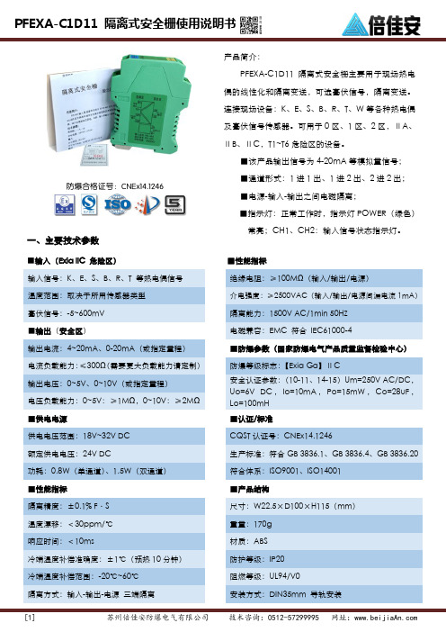
防爆合格证号:CNEx14.1246一、主要技术参数■输入(Exia IIC 危险区) ■性能指标 输入信号:K 、E 、S 、B 、R 、T 等热电偶信号 绝缘电阻:≥100M Ω(输入/输出/电源)温度范围:取决于所用传感器类型 介电强度:≥2500VAC (输入/输出/电源间漏电流1mA )毫伏信号:-5~600mV 隔离能力:1500V AC/1min 50HZ ■输出(安全区)电磁兼容:EMC 符合 IEC61000-4输出电流:4~20mA 、0-20mA (或指定量程)■防爆参数(国家防爆电气产品质量监督检验中心) 电流负载能力:≤300Ω(需要更大负载能力请定制) 防爆等级标志:【Exia Ga 】ⅡC输出电压:0~5V 、0~10V (或指定量程)安全认证参数:(10-11、14-15)Um=250V AC/DC ,Uo=6V DC ,Io=10mA ,Po=15mW ,Co=28uF ,Lo=100mH 电压负载能力:0~5V :≥1M Ω,0~10V :≥2M Ω ■供电电源■认证/标准供电电压范围:18V~32V DC CQST 认证号:CNEx14.1246额定供电电压:24V DC生产标准:符合GB 3836.1、GB 3836.4、GB 3836.20 功耗:0.8W (单通道)、1.5W (双通道) 符合体系:ISO9001、ISO14001 ■性能指标■产品结构隔离精度:±0.1% F·S 尺寸:W22.5×D100×H115(mm )温度漂移:<30ppm/℃ 重量:170g 响应时间:<10ms材质:ABS 冷端温度补偿准确度:±1℃(预热10分钟) 防护等级:IP20 冷端温度补偿范围:-20℃~60℃ 阻燃等级:UL94/V0隔离方式:输入-输出-电源 三端隔离安装方式:DIN35mm 导轨安装产品简介:PFEXA-C1D11 隔离式安全栅主要用于现场热电偶的线性化和隔离变送,可选毫伏信号,隔离变送。
P+F安全栅组态说明 ppt课件

第十步、设定Output输出参数。
PPT课件
13
温度量程下限输入到“start value”对话框中,量程上限输入到“end value”对 话框中。
在“Charachteristic”中可选择输出的模式,我们推荐选择“4-20mA NE43”,便 于对线路进行监测。
PPT课件
14
END
PPT课件
15
组态软件的安装。
PPT课件
3
第三步、安装相应的 Interface Technology 软件, 用于驱动 通讯电缆后采集所有正常连接的设备。如计算机为非win7和64 位操作系统,则选中第 1 、 2 项,然后点击“Install selected applications”,如计算机为win7和64位操作系统, 则选中第 1 、 3 项,然后点击“Install selected applications”,进行安装。
PPT课件
11
第九步、设定Input(输入)参数。
热电阻输入,需要选择电阻的输入线制,主要是 2 线制、3 线制还是 4
线制。如果选择 2 线制热电阻,则可在“lead resistance”对话框中输
入线电阻阻值,从而减少线电阻对温度测量的影响。
PPT课件
12
热电偶输入,需要选择是“外部补偿”还是“冷端温度补偿”。如果选择外部补 偿,可将室温输入到“Ext.Ref.Temp”外部参考温度对话框中,从而减小室温的 影响。如选则内部补偿,则需使用 K-CJC 补偿端子。
PPT课件
4
安装完成后,弹出如下窗口,即成功安装。
以上三个软件需正常安装,才能进行P+F安全栅组态, 即表示成功了一半。
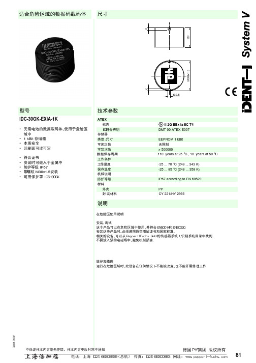
上海倍加福 IDC-30GK-EXIA-1K数据码载码体 说明书
8123.01.200
2尺寸技术参数型号
适合危险区域的数据码载码体ATEX 标志 ¬ II 2G EEx ia IIC T4EG符合声明DMT 00 ATEX E007存储器类型/尺寸EEPROM 1 kBit 可读次数 无限制可写次数> 500000数据保存周期 110 years at 25 °C , 10 years at 50 °C 工作条件工作温度 -25 ... 70 °C (248 ... 343 K)保存温度-25 ... 85 °C (248 ... 358 K)
机械说明防护等级IP67 according to EN 60529材料
外壳PP
封装材料 CY 221/HY 2966
说明
在危险区使用说明
安装,调试
这个产品可以在危险区域中使用,并符合EN50014和EN50020.
安装这类产品时,必须遵照原型测试证书和国家标准.
相关的设备,可以从Pepperl+Fuchs GmbH的传感器系统1/识别系统目录中找到.不要放入强的电磁场中,避免机械损害.
维护和修理
运行在危险区域时,此设备在任何情况下不能被改变,也不能开展修理工作.
IDC-30GK-EXIA-1K
• 无需电池的数据载码体,使用于危险区
域中
• 1 kBit 存储器
• 本质安全
• 印刷面可读可写
• 符合证书
• 安装时可嵌入于金属中
• 防 护等级 IP67
• 带 螺纹 M30x1.5安装
• 可用保护罩ICS-30GK。
- 1、下载文档前请自行甄别文档内容的完整性,平台不提供额外的编辑、内容补充、找答案等附加服务。
- 2、"仅部分预览"的文档,不可在线预览部分如存在完整性等问题,可反馈申请退款(可完整预览的文档不适用该条件!)。
- 3、如文档侵犯您的权益,请联系客服反馈,我们会尽快为您处理(人工客服工作时间:9:00-18:30)。
ISO9001K-SystemIsolated BarriersPROCESS AUTOMATIONSYSTEM DESCRIPTIONWith regard to the supply of products, the current issue of the following document is applicable: The General Terms of Delivery for Products and Services of the Electrical Industry, published bythe Central Association of the Electrical Industry (Zentralverband Elektrotechnik und Elektroindustrie (ZVEI) e.V.) in its most recent version as well as the supplementary clause:"Expanded reservation of proprietorship"2014-0431Safety (4)1.1Validity..........................................................................................................41.2Target Group / Personnel..............................................................................41.3Reference to further documentation..............................................................41.4Marking.........................................................................................................41.5Intended Use ................................................................................................51.6Improper Use................................................................................................51.7Mounting/Installation.....................................................................................51.8Operation, Maintenance, Repair...................................................................61.9Delivery, Transport, Disposal........................................................................62Product Specifications (7)2.1Function........................................................................................................72.2Housing Styles..............................................................................................82.3Terminals....................................................................................................102.4Color Identification......................................................................................152.5Status Indicators with LEDs........................................................................162.6Label Carrier...............................................................................................173Installation (18)3.1DIN Mounting Rail.......................................................................................183.2Power Rail ..................................................................................................183.3Mounting.....................................................................................................193.4Connection .................................................................................................213.5Device Configuration ..................................................................................264Operation .. (28)4.1Fault Monitoring..........................................................................................284.2Fault Output................................................................................................284.3Current and Voltage Standard Signals........................................................325Technical Specifications . (33)5.1Technical Data............................................................................................335.2Model Number Description.........................................................................365.3Dimensions (38)214-4 41Safety1.1ValidityThe chapter “Safety” is valid as instruction manual.Specific processes and instructions in this document require special precautionsto guarantee the safety of the operating personnel.1.2Target Group / PersonnelResponsibility for planning, assembly, commissioning, operation, maintenance,and dismounting lies with the system operator.Mounting, installation, commissioning, operation, maintenance and disassemblyof any devices may only be carried out by trained, qualified personnel. Theinstruction manual must be read and understood.1.3Reference to further documentationLaws, standards, or directives applicable to the intended use must be observed.In relation to hazardous areas, Directive 1999/92/EC must be observed.The corresponding data sheets, declarations of conformity, EC-type-examinationcertificates, certificates and Control Drawings if applicable (see data sheet) arean integral part of this document. You can find this information under.Due to constant revisions, documentation is subject to permanent change.Please refer only to the most up-to-date version, which can be found under.1.4MarkingThe exact designation of the device can be found on the name plate on the deviceside.Device identificationPepperl+Fuchs GmbHLilienthalstrasse 200, 68307 Mannheim, GermanyModel numberATEX approvalGroup, category, type of protection, temperature classificationStatement of conformity (where appropriate)Group, category, type of protection (where appropriate)2014-0451.5Intended UseThe devices are only approved for appropriate and intended use. Ignoring these instructions will void any warranty and absolve the manufacturer from any liability.The device must only be operated in the ambient temperature range and at the relative humidity (non-condensing) specified.The devices are used in C&I technology for the galvanic isolation of C&I signals such as 20 mA and 10 V standard signals or alternatively for adapting orstandardizing signals. Devices that incorporate intrinsically safe circuit are used for operating intrinsically safe field devices in hazardous areas.1.6Improper UseProtection of the operating personnel and the overall system is not ensured if the product is not being used according to its intended purpose.The equipment is not suitable for isolating signals in high current applications unless this is noted separately in the corresponding datasheet.1.7Mounting/InstallationPrior to mounting, installation, and commissioning of the device you should make yourself familiar with the device and carefully read the instruction manual.The device must not be installed at locations where corrosive vapors may be present.The devices fulfill a degree of protection IP 20 according to IEC/EN 60529.The devices are designed for use in pollution degree 2 and overvoltage category II as per IEC/EN 60664-1.If used in areas with higher pollution degree, the devices need to be protected accordingly.Only use power supplies that provide protection against direct contact (e.g.SELV or PELV) for the connection to power feed modules.Observe the tightening torque of the terminal screws.The installation instructions in accordance with IEC/EN 60079-14 must be observed.Intrinsically safe circuits of associated apparatus (installed in safe areas) can be led into hazardous areas, whereby special attention must be paid to maintain separation distances to all non-intrinsically safe circuits according to the requirements in IEC/EN 60079-14.214-4 6All separation distances between two adjacent intrinsically safe circuits need tobe observed in accordance with IEC/EN 60079-14.If "Ex i" protected circuits (intrinsically safe) were operated with non-intrinsicallysafe circuits, they must no longer be used as "Ex i" protected circuits.The respective peak values of the field device and the associated apparatus withregard to explosion protection should be considered when connecting intrinsicallysafe field devices with intrinsically safe circuits of associated apparatus(verification of intrinsic safety). Make sure to observe IEC/EN 60079-14 andIEC/EN 60079-25.If more channels of one device are connected in parallel, make sure the parallelconnection is made directly at the terminals of the device. When verifying theintrinsic safety, the maximum values for the parallel connection must beconsidered.1.8Operation, Maintenance, RepairThe devices must not be repaired, changed or manipulated. If there is a defect,the product must always be replaced with an original device.1.9Delivery, Transport, DisposalCheck the packaging and contents for damage.Check if you have received every item and if the items received are the ones youordered.Keep the original packaging. Always store and transport the device in the originalpackaging.Store the device in a clean and dry environment. The permitted ambientconditions (see data sheet) must be considered.Disposing of devices, packaging material, and possibly contained batteries mustbe in compliance with the applicable laws and guidelines of the respectivecountry.2014-0472Product Specifications2.1FunctionIsolated barriers are used for protection of intrinsically safe circuits in hazardous areas. They have the necessary current and voltage limitation and additionally electrical isolation between field circuit and control.The K-System consists of wide range of isolated barriers suitable for mounting on 35mm DIN mounting rail. K-System is easy to specify, integrate and expand. Our extensive line of intrinsic safe isolators for hazardous location applicationscontains over 150 different models, each containing industry leading features and benefits.Figure 2.2K-System on PowerRail214-4 82.2Housing StylesDepending on the functionality and application, K-System devices have threedifferent housing widths:⏹KC devices with 12.5 mm width⏹KF devices with 20 mm width⏹KF devices with 40 mm widthThe three housing widths versions have the same system characteristics. Alldevices from the K-System can be combined on the Power Rail.KC Device HousingUsed for high signal integrity⏹Compact 12.5mm housing⏹Maximum packing density with single loop integrity⏹Power loss only 0.8W per device2014-049KF Device HousingUsed for high channel density⏹Compact 20mm housing⏹Highest packing density on the market ⏹Requires only 5mm per channel214-4 10Used for applications with high functionality⏹Digital devices monitor speed, direction of rotation, slip, flow rates and time.⏹Analog devices monitor transmitter signals, temperature signals and loadcells.⏹Configured using PACTwareTM or keypad⏹AC/DC wide range supply available2.3Terminals2.3.1Removable Terminal BlocksThe removable terminal blocks simplify connection and control cabinetconstruction significantly. These terminal blocks offer adequate space for theconnection of leads with core cross-sections of up to 2.5mm2 (14AWG). Theterminal blocks are coded with red coding pins so misconnection of terminalblocks are eliminated.Observe the tightening torque of the terminal screws. The tightening torque is0.5Nm to0.6Nm.The 20mm and 40mm wide KF devices are factory-equipped with screwterminals. The KC devices are available with screw terminals or spring terminals.The type code of the versions of the KC-devices with spring terminals has theextension ".SP".2014-0411As an alternative to the factory-equipped terminal blocks the devices can be used with other terminal blocks:⏹Terminal blocks with screw terminals⏹Terminal blocks with screw terminals and test sockets ⏹Terminal blocks with spring terminals and test socketsThese terminal blocks are available as accessories. The terminal blocks can be easily coded with KF-CP coding pins (available separately).1Terminal blocks with screw terminals2Terminal blocks with screw terminals and test sockets 3Terminal blocks with spring terminals and test sockets214-4 12Protection against direct contactThe removable terminal blocks have different heights:⏹Height 15mm (1), (2), (3): These terminal blocks are used in applications thathave rated voltages lower than 50V AC. The insulation of the removableterminal blocks provides protection against direct contact. The insulationcorresponds to a reinforced insulation according to EN50178 for a ratedinsulation voltage of 50V AC.⏹Height 15.5mm (4), (5): These terminal blocks are used in applications thathave rated voltages higher than 50V AC. The insulation of the removableterminal blocks provides protection against direct contact. The insulationcorresponds to a basic insulation according to EN50178 for a rated insulationvoltage of 300V AC. The higher terminals are marked (X).2.3.2Terminal DesignationPlease reference appropriate device for precise terminal designation.1Terminal block with screw terminals, height 15mm2Terminal block with screw terminals and test sockets, height 15mm3Terminal block with spring terminals and test sockets, height 15mm4Terminal block with screw terminals and test sockets, height 15.5mm5Terminal block with screw terminals, height 15.5mmX Marking2014-0413214-4 142014-04152.4Color IdentificationThe color identification of the devices has the following meaning:⏹Green (1) indicates devices with DC power supply.⏹Black (2) indicates devices with AC power supply.⏹Gray (3) indicates devices with AC/DC wide range supply of•20V DC to 90V DC or •48V AC to 253V AC⏹Blue (4) indicates devices that process signals from the hazardous area1green 2black 3gray 4blue214-4 162.5Status Indicators with LEDsLEDs are often used on isolators to indicate different statuses (e. g. for powersupply, device failure, status messages, binary switching states). Standard LEDcolors are assigned to the status display according to NAMUR NE44.LED Display function Display MeaningGreen LED Power supply On Power supply OKOff Power failure or insufficient power supply – devicefaultyRed LED Device fault,device failureOn Internal fault signal, failure signal – fault/failuredisplay of causes detected inside the device,device needs replacingLine fault Flashing External fault signal, failure signal – fault/failuredisplay of causes detected outside the device,inspection and elimination of fault requiredNo fault Off No malfunction, device is operating properly Yellow LED Switching states ofbinary inputs andoutputsOn Possible causes of the output:⏹The relay is energized.⏹The NO contact (also a change-over contact)is actively closed.⏹The open collector is switched through.⏹The switching voltage generated inside thedevice is applied.Possible causes of the input:⏹An external contact is closed.⏹ A NAMUR sensor is undamped (OK rangeaccording to closed-circuit current principle).⏹ A switching signal is actively applied.Off Possible causes of the output:⏹The relay is de-energized.⏹The NO contact (also a change-over contact)is actively opened.⏹The open collector is not switched through.⏹The switching voltage generated inside thedevice is not applied.Possible causes of the input:⏹An external contact is opened.⏹ A NAMUR sensor is damped (fault rangeaccording to closed-circuit current principle).⏹ A switching signal is not applied.Table 2.1Meaning of status indicators2014-04172.6Label CarrierA label carrier for individually labeling the devices is provided in the factory.1Yellow LED "OUT"Switching state of the output2Red LED "CHK"Lead breakage and short circuit status indicator 3Green LED "PWR"Power supply status indicator1Label carrier on KC devices for 22mm x 9mm labels 2Label carrier on KF devices for 22mm x 16.5mm labels3Label carrier on KF devices (old version) for 18mm x 8mm labels214-4 183Installation3.1DIN Mounting RailThe devices are mounted on a 35mm DIN mounting rail according to EN60715.3.2Power RailTo reduce wiring and installation costs, Power Rail is the optimum solution. ThePower Rail is a DIN mounting rail with plastic insert, that delivers power to thedevices (24V DC) and transfers bus signals and a collective error message.The Power Rail is factory-equipped with cover and end caps. These parts coverempty and open segments of the Power Rail. Thus, the Power Rail is protectedfrom contamination. Additionally the cover and end caps prevent that electricallyconductive parts come in contact with the Power Rail.Power Rail is available in two versions:⏹Power Rail UPR-03Version with three leads:•two conductors for power•one conductor for collective error messaging⏹Power Rail UPR-05 (only for KFD2-WAC2-(Ex)1.D)Version with five leads:•two conductors for power•one conductor for collective error messaging•two conductors for serial data exchange2014-04193.3MountingMounting the Isolated BarrierSnap the device onto the DIN mounting rail in a vertical downward movement. See figure below.1Cover UPR-COVER 2Insert UPR-INS-033DIN mounting rail UPR-MR (35mm x 15mm)4End cap UPR-E214-20Vertical and horizontal mountingLow heat dissipation allows vertical or horizontal mounting without spacing.Operation is guaranteed over the full temperature range of the system in anymounting direction and without restriction.2014-0421Mounting the Terminal BlocksThe insulation of the removable terminal blocks protect against direct contact. If you replace the terminal blocks, observe the rated insulation voltage. See chapter 2.3.1. If the rated voltage greater than 50V AC, proceed as follows:1.Switch off the voltage.2.Connect the terminal blocks or disconnect the terminal blocks.3.4ConnectionK-System devices are available with different supply voltages.⏹24V DC power supply⏹115V AC or 230V AC power supply for applications where direct current is not available⏹AC/DC wide range supply with 20V DC to 90V DC or 48V AC to 230V ACThe supported supply voltage for each device is identified on the side plate.214-4 223.4.1Power Supply without Power RailIf devices with AC or universal power supplies are used, the advantages ofPower Rail are not available.Conventional power supplies create complicated and expensive wiring systems.After all isolated barriers are connected, there is a significant amount of wiringand more wiring must be added for extra functions such as line fault detection.3.4.2Power Supply with Power RailFor devices with a 24V DC supply voltage, use of the Power Rail reduces wiringand installation costs. The Power Rail almost completely eliminates the risk ofwiring faults and facilitates expansion.Power is supplied to the Power Rail via a power feed module which provides avoltage of 24V DC (max.4A) to a maximum of 80devices.1DIN mounting rail2014-0423The power feed module features a replaceable 5A fuse at the front. This fuse ensures that the Power Rail and connecting contacts are protected. It prevents damage caused by reverse supply voltage or by installing too many isolators. The isolators on the Power Rail feature integrated device fuses. Any faults in the isolator or in the signal leads do not affect the Power Rail supply system. The 5A fuse permits a rated current of up to 4A across the entire temperature range.The power feed module also has the task of outputting a collective error message or power failure of the isolators via a separate relay output.Alternatively, supply of the Power Rail can be provided using the power supply KFA6-STR-1.24.*. In this case, no collective error message is possible.Non-Redundant Supply with Power Feed ModulesThe power feed module mounts on the Power Rail for easy and reliabledistribution of power to all connected isolators. This method eliminates the wiring loops (daisy chain) necessary on a conventional installation without Power Rail.1Replaceable fuse 2Power feed module 3Power Rail214-4 24Redundant Supply with Power Feed ModulesTwo power supplies or a redundant power supply with two power feed modulesoffer a high degree of availability. If a power supply or the fuse in a power feedmodule fails, the redundant supply continues to energize the isolators throughtheir Power Rail connection.Direct Supply with Power SuppliesA complete power solution for a K-System installation is possible by using thefollowing power supplies:⏹KFA6-STR-1.24.4 from 115/230V AC to 24V DC/4A or⏹KFA6-STR-1.24.500 from 115/230V AC to 24V DC/500mAThe power supplies snap on the Power Rail to easily and efficiently distributepower to the isolated barriers.1Replaceable fuse2Power feed module 13Power feed module 24Power Rail2014-04251Power supply 2Power Rail1Power supply 2Power Rail214-4 263.5Device ConfigurationMany devices of the K-System can be adapted to different applications.Depending on the device different controls are available for this configuration.These controls are:DIP switchesVia DIP switches you can configure the basic functions of the device.Rotary switchesVia rotary switches you can configure the basic functions of the device.PotentiometersVia potentiometers you can configure the calibration of input and outputcharacteristics.1DIP switch1Rotary switch1Potentiometer2014-0427Keypad and LC displayVia keypad you can configure the settings of the device parameters. Measured values, fault signals and configuration settings are displayed on the LC display.Programming sockets for the connection of a PC with parameterization software PACT ware TMVia parameterization software PACTware TM you can configure the device easily. The configuration data can be edited and saved. The parameterization software helps users for maintenance, diagnostics and troubleshooting.Device configurationSet the particular controls as described in section "Configuration" of the data sheet.1LC display 2Keypad1Programming socket214-4 284Operation4.1Fault MonitoringNumerous faults can occur between measurement of the process variable andevaluation in the control system. This can lead to undesirable process statusesunder certain circumstances. These process statuses may result in plantdowntime or quality problems or even present a hazard to persons and theenvironment. Depending on the device version, the isolators enable monitoring ofthe following faults:⏹Line faultsHere, the connection cables between the isolator and field device aremonitored for lead breakages or short circuits. If a fault is detected, it is outputat the fault message output or collective fault message. The relevantswitching outputs are then switched to a de-energized state. The red faultindication LEDs signal the fault.⏹Device faultsThe isolators are designed so that internal faults are detected and reported.In the case of a power failure, the outputs are switched to a de-energizedstate.4.2Fault OutputNumerous K-System isolators monitor the field cables for lead breakages andshort circuits so that faults in the plant can be detected immediately. Line faultsare prevented from being interpreted as signals. Depending on the configurationof the devices, these faults are transmitted to the outputs at the control side and inseparate fault indication outputs as additional information.2014-0429Fault Indication OutputLine and device faults are transmitted if the device has a fault indication output (FAULT). The fault indication output is active in a normal state and inactive in a fault state (closed-circuit principle). Is it impossible to reverse the detection direction of the fault indication output.Line Fault Transparency (LFT)If the device has a signal output with line fault transparency, the fault message can also be transferred to the signal line, saving additional wiring and enabling the transfer of channel selective fault messages. A resistive passive transistor output is used for digital signals. The signals 0 and 1 are transmitted using two resistance values at the output. The output switches to high impedance in the event of a fault. Corresponding input cards are required in the controller for this line fault transparency function.214-4 30Collective Error Message on Power RailIn addition to the output of fault messages at a separate fault indication output orusing line fault transparency, the fault is also output at the Power Rail (FAULT) asa collective error message.The collective error message enables line fault detection of many isolatorswithout requiring additional wiring. In the event of a fault, a fault message signal istransmitted to the Power Rail from an isolator. The power feed module evaluatesthe signal and transmits the fault message signal to the controller by means of apotential-free contact.The potential-free contact simultaneously reports the device power failure orfailure of individual devices.2014-04311Power feed module2Fault indication on one of the devices (red LED flashes)3Process control system 4Fault indication output214-4 324.3Current and Voltage Standard SignalsThe following signals have established themselves as the standard:⏹the 0/4mA to20mA current signal⏹the 0/2V to10V voltage signalThe 0/1V to5V voltage signal is also occasionally encountered in addition to the0/2V to10V voltage signal.Analog sensor signals and digital frequency signals are converted into one of thetwo standard signals for processing in a wide variety of measurement, regulatoryand control tasks. This offers the measurement and control technician an easy-to-measure standard signal common to all manufacturers. Sensor signals areconverted into standard signals via signal converters.For more diagnostic options, the NAMUR organization published NAMURrecommendation NE43, dividing the value range of the signal (e.g. current signal)into several areas. Valid, defined measurement value information is transferredwithin the range from 3.8mA to20.5mA. Failure information is available when thesignal current is <3.6mA or >21mA i.e. outside of the range for measured valueinformation. The same applies to the voltage signal.1Failure information2Measuring information2014-04335Technical Specifications5.1Technical DataElectrical DataSafe Area Signals or Control Circuit Signals⏹0/4mA to 20mA signal level according to NE43⏹0/2V to 10V signal level according to NE43⏹0/1V to 5V signal level according to NE43⏹Current output HART compatible ⏹Current input HART compatible⏹Digital output: active or passive electronic output 100mA/30V, short-circuit protected⏹Relay output 2A, minimum load 1mA/24V ⏹Logic level 24V according to IEC 60946⏹Functional isolation or safe isolation according to IEC 61140 and NAMUR NE23Ex Signals or Field Circuit Signals⏹Transmitter power supply up to 17V DC ⏹Current output HART compatible ⏹Pt100, 2-, 3-, (4)-wire technology⏹Resistor 0Ωto 400Ω with freely definable characteristic ⏹Potentiometer⏹Thermocouples of all types, internal cold junction, external reference ⏹Current output HART compatible⏹Digital input according to NAMUR EN 60947-5-6⏹Digital output for Ex-i valves, short-circuit protectedConformity G eneral⏹Isolators with and without explosion protection, mostly with Ex ia IIC/Class I Div.1, international approvals ⏹EMV according to •EN 61326-1•EN 61326-3-2, only for devices with SIL rating, where the data sheet mentions this standard.If you operate the device with a DC supply voltage, you must ensure that the bridging of the 20ms voltage interruption is realized by the power supply.•NAMUR NE21If you operate the device with a DC supply voltage, you must ensure that the bridging of the 20ms voltage interruption is realized by the power supply.。
