三菱多功能电子测量仪
机电类毕业设计(参考)

机电类毕业设计(参考)2008-11-15 12:44:56| 分类:毕业论文收集| 标签:|字号大中小订阅第1章绪论以前,我国对电机的试验一般采用人工单机控制,时效性较差,误差也较大,很难满足测试的要求。
近几年来,我国对电机的智能检测有了很大的发展,国内电机行业的检测装备和检测技术有了较快的发展,各种检测传感器、检测仪器已比较齐备,而且性能也较稳定,为电机检测系统的研制提供了有利的条件。
但就高压电机检测系统的实际应用而言,还存在着以下不足:高压电机检测系统的自动化程度较低、系统的可靠性、安全性不够等等。
高压试验系统投资总额较高,而作为投资方的电机质检机构,希望在原有低压检测系统的基础上进行设备改造,研制出能进行高压电机试验的检测系统。
同时,制造企业由于各种因素的制约,缺少完备的型式试验设备和相关的专业技术人员,对存在的性能缺陷往往不能准确进行地诊断,分析缺陷的原因,提出明确的改进建议。
所有的电机(包括高压电机)在出厂之前都要经过型式试验和性能测试,全面达到技术要求之后才能投产或继续生产。
这些测试或试验的数据包括电机的电压、电流、转速、功率、转差率、频率、效率、温度、电阻等,这些参数是在满足GB1032三相异步电动机试验方法等国家有关标准的精度及其安全要求的基础上通过空载试验、负载试验、温升试验、转矩试验等多种试验获得的,本文所介绍的智能高压电机试验系统具有自动测试功能,通过测量数据,能够很好地反映电机性能及其质量。
1.1 电机型式试验简介电机试验是利用仪器、仪表及相关设备,按照相关标准的规定,对电机制造过程中的半成品和成品,或以电机为主体的配套产品的电气性能、力学性能、安全性能及可靠性能等技术指标进行的检验。
通过这些检验,可以全部或部分的反映被试电机的相关性能数据,用这些数据,可以判断被试产品是否符合设计要求、品质的优劣以及改进的目标和方向。
所谓型式试验是一种全面的性能试验,能够较确切地得到被试电机的有关性能参数的试验,其目的是为了确定电机的电气和机械参数是否全面达到技术要求,各种型式电机均需要通过本试验才能投产或继续生产。
MASTECH MS8226 MS8226T 3 3 4位数字多用表 说明书

目录概述 (1)开箱检查 (1)安全信息 (2)安全要求 (3)快速开始 (5)安全符号 (5)仪表面板 (6)按键功能 (7)其它功能 (8)测量操作 (9)交直流电压测量 (9)交直流电流测量 (10)电阻测量 (11)电容测量 (12)频率和占空比测量 (13)温度测量 (14)二极管测量 (15)通断测试 (16)技术指标 (17)综合指标 (17)准确度和分辩率 (18)维护 (23)更换电池 (23)更换保险管 (24)其它 (24)RS232C串行接口 (25)概述MS8226/MS8226T是一款功能齐全、性能稳定、安全可靠性高的3 3/4位的数字多用表。
仪表使用了大规模集成电路双积分的A/D转换器,具有自动量程和手动量程,所有量程都具有过载保护功能,能测量交直流电压、交直流电流、电阻、二极管、通断测试、电容、频率、占空比和温度。
仪表采用先进的两次注塑工艺,使仪表的外壳具有更可靠的绝缘性能。
开箱检查打开包装箱取出仪表,请仔细检查下列附件是否缺少或损坏,如有缺少或损坏请立即与你的供应商联系。
z数字多用表一台z使用说明书一本z表笔一副z温度探头一个z PC接口电缆一根z软件光盘一张- 1 -IEC1010 –1过压CAT.Ⅲ,使用污染等级Ⅱ的安- 2 -安全要求为避免危及使用者的安全,在使用仪表之前请仔细阅读本使用手册,并严格遵守安全警告信息和操作说明来使用本仪表。
在测量30V以上的电压;测量10mA以上的电流;测量带电感负载的交流电力线;测量电力波动期间的交流电力线时,请要特别小心以防电击。
在每次使用仪表之前都要检查您的仪表和表笔线是否有异常或破损,如果发现任何异常情况,如表笔线磨损或断裂、外壳破裂、显示器无显示等,请立即停止使用并送修。
仪表只有和所配备的表笔线一起使用才符合安全标准的要求。
如表笔线破损时,必需更换上同样型号或者相同电气规格的表笔线。
不要使用其它未经指定或认可的保险管来更换仪表内部的保险管。
UT890C+ D 3-5 6 位真RMS数字多功能测量器说明书
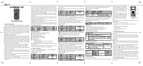
Range 600mV 0.1mV 0.001V 0.01V 0.1V 1V6V 60V 600V 1000VResolution Accuracy ±(0.5%+4)±(0.5%+2)±(0.7%+10)Range 600Ω0.1Ω0.001k Ω0.01k Ω0.1k Ω0.001MΩ0.01M Ω6k Ω60k Ω600k Ω6M Ω60M ΩResolution Accuracy ±(0.8%+5)±(0.8%+3)±(1.0%+25)Operating ManualI. General IntroductionThis brand new UT890C+/D Operating Manual is a handheld 3-5/6 digit True RMS Digital Multi-meter featuring stable performance and high reliability. Its whole circuit design utilizes a large scale integrated circuit that uses ∑△ADC converter as its core and is further equipped with full function overload protection, making it an ideal tool for users to measure the followings: DC and AC voltage, electric current, resistance, capacitance, frequency, temperature (UT890D/C+), diode, triode and continuity test.Safety Rules and Instructions● This unit is designed and produced in strict accordance with GB4793, Safety Requirements for Electronic Measuring Instrument and Safety Standards coded as IEC61010-1 and IEC1010-2-032. It complies with safe standards, such as double insulation, over voltage (CAT II 1000V, CAT III 600V) and class of pollution II. Please follow the instructions contained in this manual, otherwise the protection provided by this unit may be impaired.● You should not use this unit unless its back cover is properly secured in place, otherwise you are exposed to shock hazard. ● The range switch should be switched to a correct range.● Check the insulation layer of the test leads to ensure no damaged or broken cable.● The red and black test leads should be well inserted into the jacks that are in compliance with the measurement requirements to ensure good contact.● The input signal should not exceed the specified limit value to avoid shock or unit damage.● It is prohibited to change range when measuring voltage or electric current so as to avoid unit damage.● Damaged fuse must only be replaced with fuse with identical specification.● To avoid electric shock, the potential difference measured between “COM” and earth “ ” should be no more than 1000V. ● To avoid electric shock, test with great caution in case the voltage to be measured maybe higher than DV 60V or AC 30Vrms. ● Battery should be replaced in time so as to ensure measurement accuracy when the LCD displays “ ”.● Power should be turned off immediately upon the test is completed and battery should be taken out if it may not be used for a long period of time.● Do not use the unit under an environment with high temperature and high humidity, especially not store it in a wet place as the dampened unit may perform badly.● Please do not change the circuit of the unit arbitrarily so as to avoid unit damage or safety hazard.● Maintenance: Please use wet cloth and mild detergent rather than abrasive material or solvent for the cleaning of its exterior housing.III. Characteristics● More than 30 functional ranges are available.● LCD display, visible area 63×29mm.● Over range display “OL”.● Maximum displayed value 5999.● Overload protection for all ranges.● Auto power off.● Temperature scope:Working temperature: 0℃~40℃(32℉~104℉) Storage temperature: -10℃~50℃(14℉~122℉)● Low battery indicator: The symbol “ ” will be displayed at top left of the LCD.● It has functions, including data hold, measurement of maximum/ minimum value, relative measurement, backlight, etc.II. Symbol DescriptionIV. Technical IndexesAccuracy: ±(α% reading plus figure), 1 year warranty period Environment Temperature: 23℃±5℃ Relative humidity:<75%1. DC VoltageInput impedance: 1GΩfor the range of 600mV while 10MΩ for all2. AC VoltageRange 6V 0.001V 0.01V 0.1V 1V60V 600V 750VResolution Accuracy ±(0.8%+3)±(1.0%+10)Input impedance: 10MΩfor all the ranges.Frequency scope: 40Hz – 1KHz (Only applicable to sine wave and triangular wave, but only being referable for other waves whose frequencies are equal or higher than 200Hz.)Guaranteed Accuracy: within 5~100% of its range and allow less t han 5 figures of remaining reading in case of short circuit.Overload Protection: 750Vrms or at a peak value of 1000Vp-p.Display: True RMS 3. DC CurrentRange 60μA 0.01μA 0.001m A 0.01mA 0.1m A 0.01A6mA 60mA 600mA 20AResolution Accuracy ±(0.8%+8)±(1.2%+5)±(2.0%+5)Maximum input current: 20A (measuring electric current between 5A and 20A, testing time ≤10 seconds, Interval≥15 mins). Measuring voltage drop: 600mV when at its full range.4. AC CurrentRange 6mA 0.001m A 0.01m A 0.1mA 0.01A60mA 600mA 20AResolution Accuracy ±(1.0%+12)±(2.0%+3)±(3.0%+5)Frequency scope: 40Hz – 1KHz (Only applicable to sine wave and triangular wave, but only being referable for other waves whose frequencies are equal or higher than 200Hz.)Guaranteed Accuracy: within 5~100% of its range and allow less Maximum input current: 20A (measuring electric current between 5A and 20A, testing time ≤10 seconds, Interval≥15 mins) Measuring voltage drop: 600mV when at its full range Display: True RMS 5. ResistanceRange of 600Ω: measured value=displayed value - value shown when Overload protection: 600Vrms. 6. CapacitanceRange 9.999n F 0.001nF0.01nF~ 0.1μF 1μF 10μF99.99nF~ 999.9μF 9.999mF 99.99mFResolution Accuracy±(5.0%+35)±(2.5%+20)±(5.0%+10)10mF≤C≤20mF:±(10.0%+5)>20mF:reading is for reference onlyRange: Auto (Reading for distributed capacitance of test leads may be shown when the unit is in open circuit. It is recommended to use7. FrequencyRange9.999Hz ~10.00MHz0.001Hz~0.01MHzResolutionAccuracy ±(0.1%+5)Range: Auto Input frequency:≤100KHz: 100mVrms≤Input frequency≤30Vrms ;>100kHz~1MHz: 200mVrms≤Input frequency≤30Vrms; >1MHz: 600mVrms≤Input frequency≤30Vrms; Overload protection: 600Vrms .8.Diode & Buzzer Continuity TestRange DescriptionDisplay forward voltage of the diode under test (approximate value) and the range scope is 0~3V.If it is equal or less than 10Ω, the buzzer beeps, indicating circuit is closed; if it is equal or more than 100Ω,the buzzer remain silence, indicating open circuit with a voltage of approximately 1V. Overload protection: 600Vrms .9. hFE Test for Transistors Range DescriptionhFETest ConditionIt can be used to test hFE specificiations for Transistors of NPN or PNP type. Display range: 0-1000βBase current is about 10μA, Vce is about1.2V 10. Temperature Test (Only for UT890C+)Accuracy ±3±5±(1.0%+3)±(1.5%+5)±(2.5%+5)±(2.0%+3)Function RangeResolution Temperature ℃Temperature ℃-40~0℃1℃>0~100℃>100~1000℃-40~32F 1F>32~212F >212~1832FV. How to Use it:Instructions before operating(1). Once the unit is powered up, please check the 9V batterycontained in this unit, and if the battery voltage is insufficient, there will be asymbol “ ” being displayed on the screen, then the battery should bereplaced to ensure measurement accuracy.the jacks for test leads warns that for the prevention of internal circuit from being damaged, the input voltage or current should not exceed the rated value.(3). Before measuring, the range switch should be switched into the range needed.123456 (see Fig. 1)①② LCD③ Combination keys: MAX MIN/④ Range switch⑤ Jack for transistor testing ⑥ Input Jack1. DC Voltage Measurement(1). Insert the black test lead into “COM”, while insert the red test lead into “V”.the test leads in parallel with the power or load under test, the polarity shown by the unit is the polarity of the terminal connected by the red test lead.1) If the voltage being measured remains unknown, turn the range switch into the maximum range first and then gradually adjusting it downward.2) If “OL” is shown on the LCD, it indicates that it has exceeded the range, so the range should be switched into a higher one.higher than 1000V should be input into the unit, as though it is possible to display a higher voltage, but this may incur a risk of damaging internal wiring!4) In case the input impedance is around 10MΩ, it may result in measurement error if such load is connected into a circuit with high impedance. Under most circumstances, if the circuit impedance is less than 10kΩ, then the error is ignored (0.1% or even lower).5) Especially be cautious to avoid shock when measuring high voltage. 2. AC Voltage Measurement(1) Insert the black test lead into “COM”, while insert the red test lead into “V”.P/N: 110401105881X REV.0 DATE:2016/06/08(2) Switch the range switch into the range “ ”. Then connect thetest leads in parallel with the power or load under test.1) Refer to the No. 1, 2, 4 and 5 of notes for DC voltage measurement.higher than 750V should be input into the unit, as though it is possibleto display a higher voltage, but this may incur a risk of damaginginternal wiring!1) If the current being measured remains unknown, turn the rangeswitch into the maximum range first and then gradually adjusting itdownward.2) If “OL” is shown on the LCD, it indicates that it has exceeded therange, so the range should be switched into a higher one.indicates that no voltage higher than 20A should be input into theunit, otherwise F2 fuse may be blown.3. DC Current Measurement(1) Insert the black test lead into “COM” first, then when measuringcurrent equal or less than 600mA, insert the red test lead into “mAμA”,otherwise, insert the red test lead into the jack for 20A.(2) Switch the range switch into the range “ ”. Then connect thetest leads in series with the load under test, the polarity shown bythe unit is the polarity of the terminal connected by the red test lead.4. AC Current Measurement 1) Insert the black test lead into “COM” first, then when measuringcurrent equal or less than 600mA, insert the red test lead into “mAμA”,otherwise, insert the red test lead into the jack for 20A.2) Switch the range switch into the range “ ”. Then connect thetest leads in series with the load under test.Refer to No. 1), 2) and 3) of the Notes for DC current measurement.5. Resistance (1) Input the black test lead into “COM”, while insert the red test lead into “Ω”. (2) Switch the range to range “Ω” and connect the test leads in Notes NotesNotes Notes Notes Notes 1) To ensure measurement accuracy, for the range of 600Ω:measured value=displayed value - value shown when test leads are short connected.2) If the resistance under test is higher than the range selected, the unit will display “OL”. Then a higher range should be selected. Forany resistance higher than 1MΩ or even higher, it may take a few seconds for the reading to become stable, which is normal whenmeasuring high resistance.3) The red test lead can also be used to check whether or not F1 or F2 has been blown. If the “mAμA” jack is tested to be 1MΩ and “A” jack is tested to be 0Ω, then the fuse acts good. If the unit displays “OL”, then the fuse has been blown.4) In case of no input, i.e. the case of open-circuit, the unit displays “OL”.5) When checking the impedance of an internal circuit, the circuitunder test must be cut off from all power sources and all capacitivecharge must be discharged.6. Capacitance MeasurementThe unit may display a reading even if there is no input at all, whichis the distributed capacitance of the test leads. For the measurementof a resistance less than 1μF, this value has to be deducted from thefinal measured value to ensure measurement accuracy. Therefore, the relative measurement function of this unit can be used to haveit automatically deducted for the convenience of checking reading.1) The unit will display “OL” in case the capacitance to be measuredhas been short connected or exceeds the maximum range of theunit, the displayer will show “OL”.2) For the measurement of large capacitance, it is normal for theunit to take several seconds to stabilize its reading.3) To avoid unit damage or harm to the personal safety, the capacitorto be tested must have all its residual charge discharged before thetest, which is especially the case for capacitor with high voltage. 7. Frequency Test1. Insert the red test lead into “Hz” jack, while insert the black testlead into “COM” jack.2. Switch the range switch into the range “Hz”. Then connect thetest leads in parallel with the frequency source, frequency valuecan thus be read directly from its displayer.The input frequency must comply with the requirements stipulated by the Technical Indexes.8. Test of Diode Insert the black test lead into “COM” jack, while insert the red test lead into “V” jack (the polarity of red test lead is “+”). Switch the rangeswitch into the range “ ”. Then connect the test lead with the diode under test, the reading is the forward voltage drop of the diode. If the diode under test is in open circuit or its polarity is reverse connected, the unit will display “OL”. For silicon p–n junction, approximately 500~800mV is generally considered normal.1) When measuring a connected diode, the circuit under test mustbe first cut off from all power sources and all capacitors must haveall their residual charge discharged.2) Only a diode with approximately 0~3V voltage can be measured.9. Buzzer Continuity Test Insert the black test lead into “COM”, while insert the red test lead into “V”. Switch the range switch into the range “ ” and then connect the test leads into the circuit under test. If both ends of the circuit has a resistance higher than 100Ω,it is considered that the electric circuit is disconnected and the buzzer remains silence. If the resistance between both ends is found to be equal or less than 10Ω, it is then considered that the electric circuit is well connected and the buzzer When measuring an energized circuit, the circuit under test must first be cut off from all power sources and all capacitors must have all their residual charge discharged. 10. hFE Test for Transistors (1) Switch the range switch to the range “hFE”.(2) Once the transistor has been confirmed whether to be a NPN or PNP type, insert its base, emitter and collector separately into corresponding jacks on the panel.(3) Approximate hFE value will be displayed on the displayer. Test condition: 1b≈10μA, Vce≈1.2V 。
PLC线束说明书
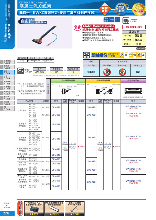
三菱电机PLC线束欧姆龙PLC线束基恩士PLC线束松下PLC线束横河电机PLC线束富士电机PLC线束光洋电子工业PLC线束西门子PLC线束施耐德PLC线束ABPLC线束2013.11▲2014.10基恩士 KV/KZ系列线束(使用广濑电机制连接器)长度单位0.1m连接器端子台(欧式弹簧螺丝紧固型KV/KZ系列线束b P.3930b P.3919b P.2695PLC定制服务细径※除标准型号外,还提供免费追加加工及定制No.服务,详情请见b2811页。
全球通用26992700继电器多层信号灯·旋转报警灯机器设备线束端子台AC /DC 风扇开关电源·噪音滤波器·变压器LAN 线缆·光纤测量仪表LED 灯测量通信线束开关按钮·开关盒·指示灯·蜂鸣器连接器线束压着端子·测试用端子电路保护器·保险丝连接器电源排插配线工具AC 电源线·接插件固定部件保护管·软管·线槽电缆扩展卡键盘·鼠标·周边产品显示器·显示器支架检测探头·镜头·附件箱体技术资料索引产品目录交易指南2013.11▲2014.102线束产品2701三菱电机 PLC 线束欧姆龙 PLC 线束基恩士 PLC 线束松下 PLC 线束横河电机 PLC 线束富士电机 PLC 线束光洋电子工业PLC 线束西门子 PLC 线束施耐德 PLC 线束ABPLC 线束2013.11▲2014.10连接器线缆非卖品部品表2702继电器多层信号灯·旋转报警灯机器设备线束端子台AC /DC 风扇开关电源·噪音滤波器·变压器LAN 线缆·光纤测量仪表LED 灯测量通信线束开关按钮·开关盒·指示灯·蜂鸣器连接器线束压着端子·测试用端子电路保护器·保险丝连接器电源排插配线工具AC 电源线·接插件固定部件保护管·软管·线槽电缆扩展卡键盘·鼠标·周边产品显示器·显示器支架检测探头·镜头·附件箱体技术资料索引产品目录交易指南2013.11▲2014.10KEYENCE PLC Harnesses基恩士PLC 线束基恩士 KV /KZ 系列线束 印字表无信号名标记的引脚为未接线。
N4L PSM1700、PSMetriQ PSM1735多功能测量仪说明书

Phase Sensitive Multimeters A new generation of versatile measurement instrumentsPSM1700 PsimetriQ PSM1735 NumetriQ10uHz to 1MHz 10uHz to 35MHzIn a world where engineers from many different application areas require ever increasing speed, flexibility and measurement accuracy, N4L introduce a new generation of versatile measurement instruments that offer leading performance in every mode without the compromise on accuracy or the additional cost that is commonly associated with such flexible instruments.Utilising the latest DSP and FPGA technology to optimise the use of innovative analogue hardware, many measurements functions can be derived with great precision from the basic elements of true rms voltage on two measurement channels plus the phase angle between them. It is from this fundamental relationship between independent voltages and their relative phase angle that the phrase ‘Phase Sensitive Multimeter’ was derived and this is also the key to the unique combination of performance versatility and value provided by the PSM range.Versatility without compromiseWhether you will make use of just one or all six of the primary measurement modesincluded in the PSM1700 and PSM1735, you can be sure of the exceptionalaccuracy, speed and ease of use that only the latest design technology can provide.Frequency Response AnalyserIncorporating a digitalsignal generator, twodifferential auto-rangingvoltmeters, auto-scalefrequency plots andintuitive setup stored intonon-volatile memory;the PSM range bringsaccurate and simpleto operate frequencyresponse analysis withinthe grasp of many whocould not previouslyconsider an FRAFeaturesDifferential inputsFast sweep with up to 20 frequency steps per secondDFT analysis giving exceptional noise rejectionAutomatic Gain/Phase margin computationStorage of results into non-volatile memoryFRA Example applications•Power supply gain and phase analysis•Electronic filter design and test•Speaker and amplifier test•Mechanical vibration analysis•Electro-Mechanical control loop analysis PSM1700 with N4L injection transformer testing an SMPSSelection of the mostsuitable display formatis very easy, switchingbetween real time,tabular or graphicalpresentation from anymode with a single keystrokeFRA table with cursor point selectedReal time mode at cursor pointIn real time mode, thedisplay functions are userselectable and can bepresented in any orderand at any of three zoomlevels. Cursor keys canthen be used to adjustamplitude and frequencywith selectable step sizeto provide completecontrol of test conditions.Vector VoltmeterUnique to the VVMmode is a null meterdisplay that providesthe feel of traditionalanalogue instrumentswhile maintaining theprecision of a 6 digitphase display and 1milli-degree phaseresolution.A high stability signal generator with direct digital synthesis, true rmssensing voltmeters and discreet fourier analysis combine to providephase measurement accuracy beyond any comparable product.FeaturesSimultaneous measurement of all functionsSynchronised to internal or external frequency sourceVVM Example applications•Electrochemical materials analysis•Current transformer testing•Phase meter calibrationLCR MeterWhether using an external shunt, an LCR Active Head or the Impedance Analyser Interface; LCR mode provides all impedance parameters quickly and accurately either at single frequencies or over a user defined frequency sweep.LCR Head – 10uHz to 5MHz IAI – 10uHz to 35MHzPSM1700 with LCR Active HeadPSM1735 with Impedance Analyser Interface6 digit resolution and exceptional phase stability permit testing of the most demanding components such as low ESR capacitorsAny point in a sweep can be selected with a cursor and viewed in a detailed results table.FeaturesWide frequency rangeFreq, Phase and Tan Delta to 6 digits Passive shunt or active head options Graph or table of any function Sweep results store to memoryLCR Example applications• Component testing • Electrochemistry• Circuit impedance analysis • Testing resonanceIn addition to providing the raw data from which all otherfunctions are derived, each channel can be used directly for applications requiring precision rms measurement. Unlike many voltmeters, AC and DC components are quantified separately and dBm, peak, CF and surge values are displayed.Both units utilise independent differential circuits permitting simultaneous analysis of two points at a different potential. For example, the input and output on voltage converter or two windings on a transformer.RMS VoltmeterPower MeterThe combination of true rms measurement channels, precision phase analysis, high speed computation and a versatile graphic display provide an ideal solution to many applications that involve rapid changes in power.FeaturesReal time true rms measurement withno missed data.Synchronisation with fundamental down to 10ms period.Datalog of up to 4 functions stored into non-volatile memory.Watch results during datalog capture with scroll display.Real time DFT harmonic analysis.Power Meter applications• Power profile testing • SMPS standby analysis • Distortion analysis • PFC testingWatts graph with cursor at log no. 2351Real time display after datalogHarmonic AnalyserThe Harmonic Analyser mode simultaneously measures individual harmonic components and total harmonic distortion values on both measurement channels.Discrete Fourier Transform algorithms permit fundamental harmonic components to be quantified accurately even in the presence of noise and distortion.PC control, data capture and file storagePSMcomm software provides control of all primary PSM functions with graphical or tabular data presentation, dual cursor measurements, an automatic gain phase margin function plus print, copy, save to file and firmware download.CommVIEW PC software supplied as standard, provides script file instrument control, result storage in .txt format and firmware download.PSM1700 and PSM1735Frequency Response AnalyserMeasurement Magnitude, gain (CH1/CH2 or CH2/CH1), gain (dB), offset gain (dB), phase (°) Frequency range 10uHz to 1MHz 10uHz to 35MHz20mHz to 500kHz with ext source 20mHz to 500kHz with ext source Gain accuracy in dB 0.02dB < 1kHz 0.01dB + 0.001dB/kHz < 1MHz 0.05dB < 10kHz 0.1dB + 0.04dB/MHz < 35MHz0.1dB + 0.001dB/kHz < 1MHz Phase accuracy 0.02° < 10kHz 0.02° < 10kHz0.02° + 0.003°/kHz < 1MHz 0.05° + 0.0001°/kHz < 35MHzFrequency source Generator or CH1 input Measurement Real-time DFT, no missing data Speed Up to 100 readings per second FilterSelectable from 0.2 secondsResolution5 or6 digitsAccessories and PortsStandard accessoriesProbes 2 off with PSM1700 – 4 off with PSM1735Leads Output, RS232, PowerSoftwareCommVIEWDocumentationCalibration Certificate, User ManualPSM1700 PSM1735Vector VoltmeterMeasurement In-phase, quadrature, tan Ø, magnitude, phase, in-phase ratio,rms, rms ratio, LVDT differential, LVDT ratiometricFrequency range 10uHz to 1MHz 10uHz to 35MHz20mHz to 500kHz with ext source 20mHz to 500kHz with ext sourceBasic accuracy (ac) 0.05% range + 0.05% reading + 0.05mV < 1kHzBasic + 0.02%/kHz < 10kHz Basic + 0.001%/kHz < 10kHz Basic + 0.2% + 0.002%/kHz < 1MHz Basic + 0.002%/kHz < 1MHzBasic + 1.6% + 0.4%/MHz < 35MHzLCR MeterFunctionsL, C, R (ac), Q, tan delta, impedance, phase – Series or parallel circuit Frequency range 10uHz to 1MHz 10uHz to 35MHzCurrent shunt External or N4L active head or Impedance Analysis InterfaceRangesInductance – 100nH to 10kH (LCR Head or IAI) Capacitance – 10pF to 1000uFResistance – 10mΩ to 100MΩBasic accuracy 0.1% + tolerance of selected current shuntSweep capabilityAll ac functionsTrue RMS VoltmeterChannels2Frequency range DC to 1MHz DC to 1MHz1MHz to 500kHz fundamental onlyMeasurementrms, ac, dc, peak, cf, surge, dBmBasic accuracy (ac) As VVM + 0.2mV As VVM + 0.05mV Accuracy (dc)0.1% range + 0.1% reading + 1mV 0.1% range + 0.1% reading + 0.5mVPower MeterMeasurementsW, VA, PF, V, A, - total, fundamental and integrated, power harmonics Frequency range 20mHz to 1MHz 20mHz to 1MHz1MHz to 500kHz fundamental onlyCurrent shunt External or use N4L power adaptor Current accuracy As voltage + external shunt toleranceWatts accuracy 0.15% VA range + 0.15% reading 0.1% VA range + 0.1% reading+ external shunt tolerance + external shunt toleranceHarmonic AnalyserScanSingle or series Frequency range 10uHz to 1MHzMeasurement Harmonic, series THD or difference THDMax harmonic50PortsRS232Baud rate to 19200RTS/CTS flow controlParallel8 output, 4 input – 25 Pin D TypeAnalog output 0V to +4V on any measured function – BNCSync output Pulse synchronised to generatorExtension ports 2(N4L accessories) 15 pin female D type and 6 pin mini-din LAN (option L) 10/100 base-T Ethernet auto sensing RJ45GPIB (Option G)IEEE488.2 compatiblePSM17xxPSM1700PSM1735DatalogFunctionsUp to 4 measured functions user selectable Datalog Window From 10ms with no gap between each log MemoryRAM or non-volatile up to 8000 recordsInput RangesInputs2 differential 2 balanced differential Connectors Isolated BNCDual grounded BNCCoupling ac or ac+dcMax input 100Vpk from earth 10Vpk from earth Input ranges 100V, 30V, 10V, 3V, 1V, 300mV, 10V, 3V, 1V, 300mV, 100mV, 30mV,100mV, 30mV, 10mVpk 10mV, 3mV, 1mVpkScaling 1 x 10^-9 to 1 x 10^9RangingFull auto, up only or manualInput impedance1M // 50pF (exc. leads) 1M // 30pF (exc. leads)Signal GeneratorTypeDirect digital synthesisFrequency 10uHz to 1MHz 10uHz to 35MHz Waveforms Sine, triangle, square, sawtooth Sine, square (1MHz) Accuracy Frequency ±0.05% Frequency ±0.05% (with no trim) Amplitude ±5% < 100kHz Amplitude ±5% < 10MHzAmplitude ±10% < 1MHz Amplitude ±10% < 35MHzImpedance 50Ω ±2% Output voltage 0V to ±10VpkOutput resolution 5mV 50uV to 5mV level dependentOffset0V to ±10Vpk Offset resolution ±10mVClock rate 11.52MHz 150MHzConnectorGrounded BNCHigh Speed Data StreamingRate 1500 readings/s maxWindow 660us to 1s Synchronized to waveformBuffer8000 resultsGeneralDisplay320 x 240 dot LCD – white LED backlightAlarm Any displayed functionhi, lo, inside window, or outside windowProgram stores 100, one loaded on power upSweep stores 30, all parameters in any sweep functionRemote operation Full capability, control and data Size170H x 350W x 250D mm approxTemperature 5 to 35°C Weight4kg approxPower supply90-264V rms 47-63Hz 30VA maxAll specifications at 23°C +/- 5°C. These specifications are quoted in good faith but Newtons4th Ltd reserves the right to amend any specification at any time without noticeMeasurement specificationsSystem specifications。
库仑法微量水分测定仪三菱化学CA-310使用说明书
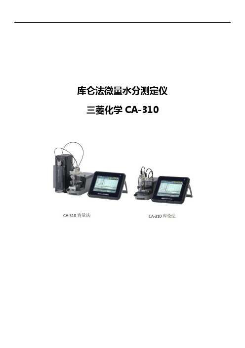
库仑法微量水分测定仪三菱化学CA-310目录一、产品简介 (3)二、仪器特点 (3)三、技术参数 (5)四、应用领域 (6)五、仪器适应标准 (6)六、测定原理 (7)七、安装与组合 (8)八、可选组件 (9)九、设备质保 (12)一、产品简介三菱化学分析公司,自1973年以来一直在研究、开发卡尔·费休水分测定仪和试剂,发布的CA-310型号是最新型号的库仑法卡尔·费休仪器。
四十年来三菱化学在应用库仑法测定微量水分样品的技术上一直处于世界领先地位,全新型号CA-310型微量水份测定仪操作方便,在原先型号CA-200基础上升级,不仅精度提高,而且可以连接多种汽化器测量固体水分,延伸了原先CA-200的使用领域。
二、仪器特点1.预定时间-自动开机,仪器自动稳定,不必在检测前漫长等待。
2.高速电解模式:仪器的稳定速度和检测速度更快,提高检测效率同时也间接降低了卡尔·费休试剂及其他耗材的损耗。
3.操作标准流程记录(S.O.P):可在仪器中录入一个检测某种样品的标准操作流程,之后仪器会自动提示实验人员按标准操作方法进行样品检测。
4.8.4英寸彩色触摸式显示器,操作界面直观清晰,中文操作界面。
2、多彩视窗:采用彩色超大屏幕显示。
5.更高的检测精度:在理想环境下检测痕量级水分(绝对含水量5μg)能有良好的重复性。
6.主控台至多可连接4个检测通道,多台通道可为实验结果进行更好的参照,同时也提高了检测效率。
7.主控台可无线控制检测通道(选配)。
8.步进式温度控制(专利号3284783):气化装置通过检测样品水分的蒸发速度自动确定最佳的加热温度。
9.可选用有隔膜或无隔膜发生电极:10.无隔膜电极:可使用单组份AQUAMICRON®通极溶液,更方便日常换液维护。
11.有隔膜电极:可测样品品种多,可测定酮类、低羟基酸、某些醛类等特殊物质。
12.数据完整性:支持GLP/GMP。
13.USB输出/输入接口:可保存测定结果、各种设定的对内连接口/对外连接口。
三菱Q 系列PLC 串行通讯模块与山武温控仪的通讯

三菱Q系列PLC串行通讯模块与山武温控仪的通讯三菱电机自动化(上海)有限公司深圳办事处李剑锋摘要:在工业控制中,可编程控制器(PLC)使用非常广泛。
然而在设备控制中经常使用到不少现场控制仪表,这些仪表通过与PLC交换数据,在设备控制中发挥着各种各样的作用,而且他们与PLC 的通讯方式也是多种多样的。
本文详细介绍了三菱Q系列PLC与山武温度仪通过RS485协议通讯的应用。
Abstract:In the industry control, the PLC used very popular. But in the equipment control, many instruments are be used, these instrument communication with PLC and exchange data. They play various roles in the equipment control and there are various communication way. The article introduce the MITSUBISHU Q series PLC used RS485 protocol to communicate with the YAMATAKE controller SDC15.关键词:三菱Q系列PLC 串行通讯 RS485通讯温控仪Keywords:MITSUBISHI Q series PLC serial communication RS485 temperature controller一、引言Q系列PLC是三菱全新的一款中大型PLC,它和小型系列FXPLC不一样,采用模块化结构,处理功能非常强大,广泛应用于机械设备、生产线控制场合,也应用于电厂、水处理等大型项目中。
在工业控制场合中,网络通信应用越来越广泛,而三菱公司的Q系列PLC共有三层网络,上层信息层,也即以太网层,用于上位计算机和现场PLC之间的数据通讯;中间控制层,即为H网,用于PLC与PLC之间的数据通讯;底层设备层,即为现场总线CC-Link,用于控制现场的I/O输入以及多方厂家的控制设备。
款三菱帕杰罗(PAJERO_CHINA)V87V97V93整车电路图手册(一)(

款三菱帕杰罗(PAJERO_CHINA)V87V97V93整车电路图手册(一)一、整车电路概述款三菱帕杰罗(PAJERO_CHINA)V87V97V93车型采用了高度集成化的电路系统,确保了车辆在各种工况下的稳定性和安全性。
本手册将为您详细解析整车电路的结构与原理,帮助您更好地了解和维护爱车。
1. 电源系统电源系统是整车电路的核心部分,主要包括蓄电池、发电机、电压调节器等组件。
蓄电池为车辆提供启动电流,发电机在发动机运行过程中为车辆供电,电压调节器则保证输出电压稳定。
2. 启动系统启动系统主要由启动机、点火开关、启动继电器等组成。
当点火开关处于启动位置时,启动继电器吸合,启动机带动发动机飞轮旋转,实现发动机启动。
3. 点火系统点火系统包括点火线圈、火花塞、点火控制器等部件。
点火控制器根据发动机转速和负荷,控制点火线圈产生高压电流,使火花塞放电,点燃混合气。
4. 照明系统5. 信号系统信号系统主要包括转向灯、危险报警灯、喇叭等。
转向灯用于指示车辆行驶方向,危险报警灯在紧急情况下提醒其他车辆,喇叭用于发出警示声音。
6. 仪表与显示系统仪表与显示系统包括车速表、转速表、水温表、燃油表等,为驾驶员提供车辆运行状态信息。
行车电脑显示屏可显示瞬时油耗、续航里程等信息。
7. 电动门窗与中控锁系统电动门窗系统包括车门玻璃升降器、门锁电机等,实现门窗的自动升降和锁止。
中控锁系统可远程控制车门锁止,提高车辆安全性。
8. 空调与暖风系统空调系统通过压缩机、膨胀阀、蒸发器等部件,实现车内温度调节。
暖风系统利用发动机冷却液循环,为车内提供暖气。
本手册将分多个部分为您详细介绍款三菱帕杰罗(PAJERO_CHINA)V87V97V93车型的整车电路图,敬请关注后续内容。
款三菱帕杰罗(PAJERO_CHINA)V87V97V93整车电路图手册(一)二、电路保护与诊断9. 保险丝与继电器车辆电路系统中,保险丝和继电器起着至关重要的作用。
索佳产品综合介绍_2007版

定向精度:±20″
精确给出任何时间、任何地点、 任何气象条件下的真北方向。
陀 螺 全 站 仪 的 系 统 组 成
陀螺全站仪主要由陀螺 仪和电子全站仪组成
陀螺测量程序
内 置 两 种 陀 螺 测 量 程 序
跟踪(逆转点) 测量
全中文操作
中天法测量
陀螺摆观测
陀螺摆观测
陀螺摆观测
煤矿贯通测量中的应用
导向光装置GDL2
3.5m
3.5m 3.5m 3.5m 100m
1.3m – 150m
SETx030R系列
SETx130R系列
SETx30R系列
SETx30RK系列
SETx10系列
SETx10K系列
测角部
测角部采用RAB绝对数码度盘;大大减小了由照准部转动所带来的系动误差。
特点 CCD 线形图象感应器
MONMOS系统全站仪
NET1
NET05
马达驱动
自动跟踪
自动照准 WinCE 操作系统
MONMOS系统的特点
●测角精度:
±0.5 ″ 、±1″
。
●测距精度:±(0.6mm+2ppm×D) ●最小距离显示:0.1mm ●最小角度显示:0.1″ ●自由设立坐标系
±0.8mm/100m或±1mm/200m。
新一代测距技术
革命化的数字处理技术,它能更快速、更精确、更可靠的进 行距离测量。最短测距优于0.3m,无协作目标最远测距优于 500m。精度:3mm+2ppm。
新型光学设计
测距信号从物镜中心发射,周边接收信号,通过相位差来 求取测量距离,确保测量数据的可靠性,提高测量精度。
全站仪测距部
索佳RED-tech Ⅱ/Ex 技术采用新型模数转换 器和滤光器,可同时对 三种不同频率的测距信 号处理,并屏蔽多余的 噪声信号;经改进的光 学和电子系统使得发射 和接收测距信号的损耗 最小,通过独特的数据 分析方法和先进处理软 件计算出所测距离,使 仪器具有更远的测程、 更快的测速和更高的测 量精度。
DS99中文使用手册 V130402
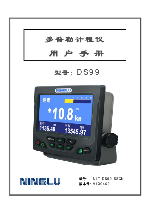
用户手册
型号:D S 9 9
编号: NLT-DS99-SSCN 版本号: V130402
安全操作
警告
内置高压电路,禁止 私自拆卸或改装本设 备,谨防电击!
注意
更换保险丝时,请按说书指 定保险丝更换。
防止水或其他物体进入显示单 元与控制单元,若水进入设备,请 立即断电。
运输、安装换能器时应小心处 理,不可重压、跌落,其表面不得 附有油漆或寄生物。
换能器与导流罩装配图(导流罩或海底阀安装二选一) ...............16 换能器与海底阀装配图(导流罩或海底阀安装二选一) ...............17 海底阀的安装与更换图 .....................................................18 系统接线 .......................................................................... 28 系统内部接线图 .............................................................. 28 显示单元 DS991 后盖图 ...................................................28 系统外部接线图 .............................................................. 29 收发单元 DS992 端子示意图..............................................29 故障维修 .......................................................................... 30 常见故障 ......................................................................30 保险丝更换 ...................................................................30 IR861 计程仪复显仪..........................................................31 IR861 安装 ..................................................................31
三菱PLC在称重系统的应用
PLC 在配料称重控制系统中的应用摘要:介绍了以三菱可编程序控制器,模拟量输入模块,COM口232无协议通信模块和触摸屏面板为组合处理单元的配料称重控制系统的组成原理,给出了系统的主要程序设计流程。
实践表明:该系统运行正确可靠且具有硬件结构简单和成本低廉的特点。
控制模式:称重传感器、信号变送器+控制器+执行器+配方;控制器是上位机程序+PLC程序,执行器是指电磁阀和电动机电磁离合器等等。
一、引言配料秤重控制系统即将两种或两种以上的物料按一定重量配比自动定量加入到混合机内,经过混合达到预定要求后自动出料的过程。
该系统广泛应用于化工,医药,饲料,建材,冶金等行业的配料混合过程控制。
与传统继电器接触装置相比,PLC具有体积小抗干扰能力强和可靠性高等优点;虽然PLC在数据处理和显示功能方面有些不足,但若采用性能稳定的计算机来完成数据采集与通信处理,不但便于提供处理精度和降低成本,而且便于通过计算机本身的COM通信接口进行数据输出和管理;选用三菱F900触摸屏代替常规显示器做人机界面,将使系统设计成本大为降低,使PLC与显示器的接口编程变得更加简单,并能使显示功能得到增强。
混凝土搅拌站控制计量系统中共有11个计量秤控制16中配料配重即11路传感器信号输入,11个变送器,每个计量秤都是3或4个传感器组成每组传感器并联或串联由4或6跟信号线接入传感器信号线接线盒,再接入TR200H变送器传感器信号是2MV/V,灵敏度高低信号传输,须经过变送器识别转换为模拟信号,送入PLC的模拟量信号采集模块;整个控制系统无需秤重计量仪表与主控制台,只需传感器接线盒、信号变送器、接线柜、PLC、模拟量输入模块、通信模块、触摸屏,HZS(HLS) 系列混凝土搅拌站控制双机同步控制系统,主要硬件由两台计算机、高性能的微电脑控制器、人机界面、高速高精度的称重单元和国际著名低压电器组成,结合自主研发的专业控制软件实现混凝土生产的自动化控制,计量系统计量精度高,制造成本低;在混凝土搅拌站电控系统的故障率调查中,计算机故障排在第一位,一旦发生故障将造成停机、停产。
三菱车系自诊断系统大全

三菱车系自诊断系统大全一、自动变速器电控系统自诊断方法1、自诊接头三菱汽车系列有3种自诊接头:12孔、16孔诊断插座或者2种同时使用。
目前,三菱汽车上全部使用的是16孔的OBD-Ⅱ型标准型诊断插座,它位于方向盘侧的仪表面盘下的熔丝盒旁。
其诊断插座的编号如图1所示。
2、故障代码读取方法针对不一致的诊断插座,读取故障代码的方法也是完全不一致的。
⑴关于12孔诊断插座,可利用发光二极管LED灯或者电压表来读取故障代码:①在12孔诊断插座第6号端子及第12号端子之间跨接1个330Ω的电阻及一个发光二极管LED灯,点火开关置于ON,LED灯就会闪烁,通过读取闪烁次数来记录故障代码。
②用电压表的方法是将电压表置于电压挡,红色表笔(+)接第12号端子(搭铁),点火开关置于ON,利用表针的摆动次数来读取故障代码。
⑵关于16孔的OBD-Ⅱ型标准型诊断插座,可利用万用表、发光二极管LED灯与发动机故障灯(Check Engine)来读取故障代码,故障代码如表1所示。
表1 三菱车系自动变速器电控系统故障代码故障代码故障内容故障代码故障内容11 TPS输出信号太高45 主油压操纵阀PCSV开路12 TPS输出信号太低46 主油压操纵阀PCSV短路若仪表面盘上有发动机故障灯,可将诊断插座6号端子用跨接线直接短路搭铁,点火开关置于ON,发动机故障灯即可闪烁出故障代码。
若无发动机故障灯,则可用万用表来读取故障代码。
如今万用表的红笔(+)接到诊断插座第6号端子,黑笔(-)接到第4号、5号端子或者直接搭铁。
利用表针的摆动次数来读取故障代码。
也可在诊断插座的第6号端子与第4号端子之间串接一个330Ω的电阻及一个发光二极管LED灯,点火开关置于ON,LED 灯即会闪烁显示故障代码。
注意:使用F4AC1型的自动变速器,则只能利用专用仪器来读取与清除故障代码。
故障代码的清除方法是将点火开关置于OFF,拆下蓄电池的负极过10s以上即可。
二、帕杰罗越野车系列安全气囊SRS系统检修帕杰罗越野车的安全气囊SRS系统的诊断装置,使用了原厂所提供的编号为MB991502的金德解码器,该测试器的要紧功能是读取故障代码、清除读取故障代码的时间信息与读取清除故障代码的时间信息等功能。
带 FR、G 端子的三菱发电机电压调节器调压原理分析与检测
带 FR、G 端子的三菱发电机电压调节器调压原理分析与检测符辉;何金戈【摘要】对带有FR、G端子的三菱发电机电压调节器调压原理进行了具体分析,同时介绍了FR、G端子的具体就车检测方法.【期刊名称】《农业装备与车辆工程》【年(卷),期】2010(000)007【总页数】4页(P49-52)【关键词】FR端子;G端子;调节器;分析;检测【作者】符辉;何金戈【作者单位】海南大学机电工程学院汽车系,海南儋州,571737;海南大学机电工程学院汽车系,海南儋州,571737【正文语种】中文【中图分类】U463.403三菱的v73、v31、v33等车型,使用B端子和L、S两针脚插头的发电机,新款格蓝迪、蓝瑟EVO、v97等车型,均使用 B 端子和 L、S、FR、G 四针脚插头的新型发电机,而且在实际的应用中,当发电机标明的额定输出 V/A相同时,经过悬空四针脚插头FR、G的两针脚,还可以替代两针脚插头的发电机使用。
使用FR、G端子的三菱车用发电机配备的是蓄电池电压感知型、综合取样法、外搭铁内置式电子调压器,20°C时调节电压均为13.9-14.9V。
调节器型号MD619268,内部电路和发动机ECU的连接如图1所示。
1 基本结构三菱发动机所用发电机由9个二极管组成,其中6只大功率整流二极管组成三相全波桥式整流电路,对外负载供电。
3只小功率管二极管与整流二极管中的三只大功率负极管组成三相全波桥式整流电路专门为发电机磁场供电。
图1 带FR、G端子的三菱发电机电路B端子连接于发电机的输出端,用于向蓄电池充电。
L端子连接于仪表板上的充电指示灯,是发电机充电指示灯的控制端。
其作用是:根据发电机是否发电或发电是否正常,独立控制充电指示灯的点亮或熄灭。
同时,在发电机发电初期,用于向发电机提供他励激磁电流。
S端子连接至电瓶的正极,是电瓶电压的侦测端,用于向调节器提供调节参考电压,调节器根据该端电压的变化输出不同宽度的磁场脉冲。
多功能测试仪
多功能测试仪(TC-V2.12k)Multi-function Tester (TC-V2.12k)浩祺电子科技2015年8月Haoqi Electronic Technology Co., Ltd.August 2015目录1综述 (3)1.1本机说明 (3)1.2功能介绍 (3)2操作指引 (4)2.1按键操作定义 (4)2.2开机 (4)2.3测试晶体管 (5)2.4自动校准 (9)2.5测试稳压二极管 (10)2.6红外解码 (10)2.7关机 (10)2.8内置锂电池电压测量 (11)2.9内置锂电池充电 (11)3性能参数 (12)4常见问题 (13)5装箱单 (13)1Overview (14)1.1Introduction (14)1.2Features (14)2Operating Instructions (15)2.1Key operational definitions (15)2.2Power on (16)2.3Detect transistor (16)2.4Selftest (20)2.5Detect Zener diode (21)2.6IR decoder (21)2.7Power off (22)2.8Built-in Li-ion Battery voltage measurement (22)2.9Charging the Battery (23)3Performance Parameters (23)4FAQ (24)5Packing List (24)多功能测试仪(TC-V2.12k)1综述1.1 本机说明① - 160x128 TFT显示屏② - 多功能按键③ - 晶体管测试区④ - 稳压二极管测试区⑤ - 红外接收窗口⑥ - Micro USB充电接口⑦ - 充电指示灯1.2 功能介绍TC-V2.12k是采用TFT图形显示的多功能测试仪。
●晶体管测试仪-自动测量NPN和PNP晶体管、N沟道和P沟道场效应管、二极管(含双二极管)、电阻(含电位器)、电感、电容、可控硅、电池(0.1-4.5V)等元器件-自动测量稳压二极管(0.01-30V)-自动校准功能●红外解码器-支持日立公司编码-红外波形显示-红外接收指示●其他-测量结果采用TFT图形显示-一键操作-自动关机(关机时长可设置)-内置大容量可充电锂电池-锂电池电压检测-支持中英文双语警告:内置锂电池,严禁将测试仪浸入水中、严禁靠近热高温源!警告:为了您的人身安全,请严格遵守锂电池使用规范和注意事项!2操作指引2.1 按键操作定义多功能按键有两种操作:●短按:按下按键不短于10毫秒且在1.5秒内松开按键●长按:按下按键1.5秒以上2.2 开机关机状态下短按多功能按键,测试仪开机并自动进行测量。
全站仪的发展史及性能特征

全站仪的发展史及性能特征徐卫国;王小华;管宏才【摘要】介绍全站仪的基本结构,各厂家的发展历史.同时对照说明各品牌的特征,为选购全站仪提供参考意见.【期刊名称】《地理空间信息》【年(卷),期】2010(008)001【总页数】3页(P148-150)【关键词】测量仪器;全站仪;技术参数【作者】徐卫国;王小华;管宏才【作者单位】湖北水利水电职业技术学院,湖北,武汉,430070;商丘师范学院,河南,商丘,476000;湖北水利水电职业技术学院,湖北,武汉,430070【正文语种】中文【中图分类】P208全站仪的测角和测距原理与电子经纬仪和测距仪的原理基本相同,只是结构不同,全站仪是将它们两者结合到一起。
全站仪由光学结构和电子电路组成。
1)全站仪的光学原理。
全站仪光路系统原理见图1。
全站仪的望远镜由物镜、分光棱镜、聚光棱镜、目镜等组成,是角度测量和距离测量的光学部分。
可见光通过望远镜进入视场,完成角度测量的瞄准工作。
物镜和分光棱镜组成测距仪光路,光路包括内光路和外光路,光纤连接发光二极管和接收管形成内光路,红外发光二极管(LED)发出的红外光通过闸门的转换经过内光路和外光路到达接收二极管,完成距离测量。
2)电气部分原理。
全站仪电气部分由两部分组成,一部分是由光栅度盘或编码度盘、光电测角仪器、放大、计数、显示、逻辑电路等组成的测角部分;另一部分是由发光二极管、接收管、电子电路组成的距离测量部分,二者之间用串行通讯连接成一个整体,从而完成电子经纬仪及测距仪的全部功能。
全站仪是从光学经纬仪发展而来的。
全站仪的产生过程如下:光学经纬仪——电子经纬仪——组合式速测全站仪——半站仪(光经+测距仪)——全站仪。
其中在组合式速测全站仪的出现前还有测距仪。
全站仪的发展又经历了四个阶段:1)普通型的全站仪:这是初期的全站仪,主要是实现测角、测距模块的整体化,仪器除了具有基本的测角和测距功能外,仅有一些简单的功能:如温度、气压改正,斜距平距互换等,软件的配置十分简单。
电子测试测量仪器行业投资价值分析及发展前景预测分析

电子测试测量仪器行业投资价值分析及发展前景预测分析一、年度计划控制主要用于检查营销效果是否达到年度计划预期,对销售额、市场占有率、费用等指标进行控制,确保年度计划所规定的销售、利润和其他目标能够实现。
(一)销售分析销售分析衡量并评估实际销售额与计划销售额的差距。
具体有两种方法:1、销售差距分析主要用来衡量造成销售差距的不同因素的影响程度。
当中既有售价下降的原因,也有销量减少的原因。
没有完成计划销售量是造成差距的主要原因。
企业还要进一步分析销售量减少的原因。
2、地区销售量分析用来衡量导致销售差距的具体产品和地区。
有必要进一步查明原因,加强该地区的营销管理。
(二)市场占有率分析销售分析一般不反映企业在竞争中的地位。
因此还要分析市场占有率或市场份额,揭示企业与竞争者之间的相对关系。
比如一家企业销售额的增长,可能是它的绩效较竞争者有所提高,也可能是整个宏观环境得到改善,市场上所有的企业都从中受益,而这家企业和对手之间的相对关系并无实质变化。
企业和营销人员应当密切关注市场占有率的变化情况。
造成市场占有率波动的原因很多,需要具体的问题具体分析:(1)市场占有率的下降,有可能出于企业战略的考虑。
有时候企业调整其经营战略、营销战略,主动减少一些不能盈利的产品,导致总销售额下降,影响了市场占有率。
如果利润反而有所增长,这种市场占有率的下降就是可接受的。
(2)市场占有率的下降,也可能是新竞争者的进入所致。
通常新竞争者的加入,会引发其他企业的市场占有率一定程度下降。
(3)外界环境因素对参与竞争的各个企业,影响方式和程度往往不同,产生的影响也不一样。
如原材料价格上涨,会对同一行业各个企业都发生影响,但不一定所有企业及同类产品都受到同样程度的影响。
有些企业推出创新的产品设计,在市场上争取到较多的客户,市场占有率反而可能上升。
(4)分析市场占有率,要结合营销机会。
机会好的企业,市场占有率一般应高于机会程度低的竞争者,否则其效率就有问题。
PMAC9900产品说明书

界面友好 该功能在用户配置显示单元时有效 用户可 以方便的通过显示单元查询数据或者是进 行现场编程
运行方便 全部的测量值 整定值都可以通过本地或者 是通讯口存取
信息透明 全部的测量数据都采用一次侧数值显示
完善的数据查询功能
PMAC®9900 提供两种方式供用户查询实时 监测的数据量
显示 通过独立单元的显示模块 用户可以任意查 询所关心的数据 并且可以进行现场的编 程 调整仪表的工作参数
功率因数计算
PMAC®9900 可以计算出全相限的功角值 用户可以查询到当前功角的超前滞后关系 与功率数据一样 接线的对应关系以及 CT 同名端关系都会影响到功率因数的实际计 算值
频率测量
PMAC®9900 工作于不同系统模式时 频率 测量的采集通道时不相同的 在三角形模式 下 PMAC®9900 是通过 C 相电压通道测量 频率 其它模式下 PMAC®9900 是通过 A 向电压通道测量频率的
显示单元
三相四线星形 三相三线星形和 DEMO 模式
序
电压
相序
电流
号
1 A 相电压
A
A 相电流
2 B 相电压
B
B 相电流
3 C 相电压
C
C 相电流
4 平均相电压 LN 平均相电流
5 AB 线电压 AB A 相电流
6 BC 线电压 BC B 相电流
7 CA 线电压 CA C 相电流
8 平均线电压 LL 平均相电流
适用于电压等级超过 600V 线 系统 适用于三相三角形系统 此时仪表电压模式设置为 3 WYE 仪表 PT USE?为 YES 设置 PT PRIMARY 参 数和 PT SECONDARY 参数 Ixx 表示电流端子 Vx 表示电压端子
- 1、下载文档前请自行甄别文档内容的完整性,平台不提供额外的编辑、内容补充、找答案等附加服务。
- 2、"仅部分预览"的文档,不可在线预览部分如存在完整性等问题,可反馈申请退款(可完整预览的文档不适用该条件!)。
- 3、如文档侵犯您的权益,请联系客服反馈,我们会尽快为您处理(人工客服工作时间:9:00-18:30)。
警报延长 时间
警报发生
最大值更新
上限值
下限值
最小值更新 0A、0V时不输出下限警报。
时间
设备启动时的便利的测试功能
在设备启动时没有电流、电压输入的状态下也应答模拟输出、脉冲输出、警报输出及通讯数据。因此可简易地进行配线及系统监控程 序的确认。
5
功能说明
LCD的功能
1
2
1 LEAD(超前)显示
2 LAG(滞后)显示
●对应DIN 96×96 尺寸 ●3P4W/3P3W 共用 ●输出选购件后装式 ●符合CE标志 ●符合欧州RoHS指令(2002/95/EC)
监控
三菱独有的ASIC给您带来 高精度的测量功能
●监控上/下限值项目达4项之多 ●谐波监控 ●测量导入/导出有功能量
显示
屏幕显示读取容易
●可显示4项项目 ●背景灯自动关闭功能
小数点位置会移动 4
便利于设备监控的上下限监控功能
●最大可上下限监控4点 在装配有ME-4201-NS96选购件的状态下,发生警报时能接点输出。 (因接点输出为1点,所以输出为被设定上下限警报项目的OR输出)
■基于LCD的上下限警报显示 可确认对应于现在值显示及最大值、最小值显示的警报发生状态。
<现在值显示画面的警报显示例>
6
■ 外形、安装、连接
23
■ 型号一览
26
■ 安全注意事项
28
概要及特长
ModBus通讯系统对应(ME96NSR-MB,选购件ME-0052-NS96)
中央监视装置
RS485/RS232 转换器
RS232
RS485(ModBus)
●最适合于PC监控的ModBus通讯系统 ●通过安装选购件ME-0052-NS96,可监控远程接点输入信号及控制接点输出信号的
接点输出(注) 1回路 无 2回路
传送功能 无
CC-Link 无
备考 ME96NSR用 ME96NSR-MB用
1
概要及特长
多彩的显示功能
●可按喜好显示 通过选择既存的显示模式及自由调整显示画面,可按自己的喜好显示。(具体的显示模式请参照第22页的「显示模式详细」)
(1) 全相同时显示 数字3段显示各相的测量值,条形图显示平均值或综合值。
适于测量有自助发电的设
备。
■后位数扩大显示 同时按 +,- 按钮2秒钟就会扩大显示后3位数。可确认测量值的微小变动。
+ ,- 同时按2秒
注.只可扩大显示画面上的电能、无功电能。 即使在显示电能的画面上扩大显示电能后位数 也不能扩大显示无功电能的后位数。想扩大显 示无功电能后位数时,调整画面显示无功电能 后进行相同的操作。
为实现测量,必须先在设定模式中进行一次电压、一次电流等的设定。从运行模式进入设定模式,设定必要的项目。没有设定的项目为
工厂出厂设定。通常的使用、按照设定菜单1(基本设定)的设定即可。
使用通讯功能的场合,设定菜单2的设定亦请进行。设定内容请参照下页以后的说明。
●设定方法
① 同时按下 SET 与 RESET 2秒,进入设定模式。
输出
从测量数据到警报的信息的 大输出范围
●可以输出7项项目 ●脉冲宽度可设
●两点输出脉冲(ME-4201-NS96)
●模拟输出范围可设
通讯
通讯功能支持开放的网络
●支持ModBus通讯 ●支持CC-Link通讯
操作
具备“高科技含量,操作简单” 的功能
●设置简单 ●操作简单
目录
■ 概要及特长
1
■ 功能说明
■无功电能的2象限/4象限测量 无功电能的测量中,象限的取法如下2种。
<2象限测量>-var
<4象限测量> -var
受电滞后及送电超前分为
一组,受电超前及送电滞
后分为一组进行测量。
-W
送电滞后 受电超前 送电超前 受电滞后
+W
不感领域只发生在var=0 (功率因数1)附近。因
-W
此功率因数=0附近不发
CC-Link传送系统对应(ME96NSR,选购件ME-0040C-NS96)
MELSECNET/10
●最适合于三菱PLC远程监控的传送系统。 ●因远程监控接点信号,所以可实现省配线、省空间。 ●数字输入可锁存30ms以上的信号,无需外部锁存回路。
MELSEC系列 CC-Link
设备异常信号 漏电异常信号 温度异常信号 断路器状态信号等
DISPLAY
DISPLAY
DISPLAY
●循环显示 带有每5秒自动切换显示的循环显示功能。即使设置在高处还是盘内,也无需按 DISPLAY , PHASE 按钮,就可确认各测量项目 和各相的测量值。
操作
动作
DISPLAY 按钮 按2秒种 测量项目每5秒自动切换。
PHASE 按钮 按2秒种
相每5秒自动切换。
电流平均值
电压平均值
功率综合值
DISPLAY 注.通过操作 PHASE 按钮可数字显示平均值或综合值。
DISPLAY
(2) 同时显示4测量项目 通过数字3段和条形图分别显示不同的测量项目而实现4项目的同时显示。
DISPLAY
DISPLAY 注.通过操作 PHASE 按钮可数字显示各相的值。
DISPLAY
3
3 条形图量程
4
4
4 过大/过小输入显示
5
5 上下限警报指针
6
6 条形图项目指示
7
7 数字项目信息显示
8
8 单位显示
9 计量显示
15
10 谐波显示
9
11 通讯显示 12 上下限警报显示
14 13
12
11 10
13 测试显示 14 设定显示
注释 : 上述LCD画面是为进行说明举出的例子,与实际画面有异。 15 数字显示
■ 想要替代功率计,所以希望只显示功率。
请只设定1个画面。
2
●条形图显示 可条形图显示各测量项目的测量值。通过条形图显示可直观把握对额定值、警报值的比例。 (1) 条形图固定显示 可固定条形图显示的测量项目。 表示固定。 还可通过 + 、- 按钮切换电压平均值、电流平均值、功率综合值、无功功率综合值、功率因数综合值、频率等。 警报指针
④所有设定结束后,选择设定菜单End,按下 SET 按键。
② 使用 + 或 - 按键选择设定菜单号码。
显示功率因素的「超前」状态 显示功率因素的「滞后」状态 显示条形图的量程 显示条形图显示的过大状态或过小状态 显示上下线警报的设定值 显示正通过条形图显示的测量项目 显示正通过数字显示的测量项目 显示数字显示值的单位 一定周期闪烁、表明正在进行电能的计量 表明正在显示谐波 表明正在通讯 表明正在发生上下限警报 表明选项输出正处在测试中 表明正处在设定状态中 测量的值通过数字进行显示
<最大值、最小值显示画面的警报显示例>
●可设定警报输出的迟延时间(警报延长时间) 可设定从超过上限值、下限值后到警报输出为止的时间。 所以可防止马达启动电流及自助发电设备启动时的频率变动导致的警报输出。 另、警报延长时间期间最大值、最小值不会更新。
电流
马达 起动电流
警报延长 时间
警报延长时间中不进 行警报输出及最大值、 最小值更新。
<CC-Link传送型号> ·最大通讯速度 10Mbps ·最大传送距离 100m(10Mbps)~ 1000m(156kbps) ·最大连接台数 42台 ·数字输入 4点(24VDC)
模拟、脉冲传送系统对应(ME96NSR,选购件ME-4201-NS96)
MELSECNET/10
●可以以4-20mA的输出远程监控A、DA、V、W、var、VA、PF、Hz、谐波电 流综合实效值及谐波电压综合失真比率。(最大4输出)
<产品系列> ■本体
型号 ME96NSR ME96NSR-MB
传送功能 无
ModBus通讯
■选购件
型号 ME-4201-NS96 ME-0040C-NS96 ME-0052-NS96
模拟输出 4回路 无 无
脉冲输出 2回路 无 无
接点输入 无
4回路 5回路
注. ME-4201-NS96的接点输出,发生上下限警报时接点会关闭。 ME-0052-NS96的接点输出,根据基于ModBus通讯控制进行开关接点。
●可通过脉冲输出远程监控电能及无功电能。(最大2脉冲) ●可通过接点输出远程监控上下限预警。(最大1点)
模拟输出 脉冲输出 警报输出
<模拟输出型号> ·4-20mA ·4输出 ·最大600Ω <脉冲输出型号> ·无电压a接点 ·35VDC 0.1A ·脉冲幅0.125、0.5、1s中选择输出 <警报输出型号> ·无电压a接点 ·35VDC 0.2A
注.警报指针在被设定警报状态时闪烁。 (2) 条形图显示数字值
可条形图显示数字3段的数字值。(但不包括数字3段都是同一个测量项目的状态) 条形图显示 所示的数字值。
条形图显示项目
●最大值、最小值显示 可显示各测量项目的最大值、最小值。因与最大值、最小值一同显示现在值,所以在显示画面上也可监控最大值、最小值。另,条 形图也显示最小值到最大值的范围。 警报指针
生不感领域。所以适于无
自助发电的设备及一般的
+var
功率因数=0附近的电容负 载的无功电能测量等场
+侧varh (受电滞后+送电超前)
合。
-侧varh (受电超前+送电滞后)
送电滞后 受电超前 送电超前 受电滞后
+var
将受电滞后、受电超前、
送电滞后、送电超前分别
做为一组进行测量。如一
+W
般的考虑方法,各区界线 区发生不感领域。
DISPLAY
(3) 基于显示模式P00的特殊显示 在显示模式P00里可自由调整显示画面。