CVI驱动程序编写入门
CVI教程
第3页
北京中科泛华测控技术有限公司
第一章
初步认识 CVI 程序设计
—— 从一个例子开始
我们的第一个示例将很简单,我们所要做的是创建一个如下的图形用户
界面(User Interface)。
当我们按下 Acquire 按扭,计算机会自动产生一个正弦波形并画在图形 显示区中;当按下 Clear 按扭后则清除正弦波形;当按下 Quit 按扭后退出 该程序。
修改后的 Edit Command Button 窗应如下图所示:
点击 OK 按扭,完成对 Command Button 属性的修改。 (2)Clear 按扭:
与以上步骤相同,双击左下方的 OK 按扭,弹出 Command 的一个 Edit Command 窗。 a. 将其 Constant Name 改为 CLEAR b. 将 Callback Function 项改为 ClearCallback
泛华测控
电话:010-62628052 至 62628055(共四线),传真:010-62628056
第4页
北京中科泛华测控技术有限公司
现在我们就开使创建该程序。首先按下面步骤起动 CVI: 开始>>程序>>National Instrument CVI>>CVI IDE
╰───────────────────────╯
免责申明:
本站(栏目、频道等)内容作品、新闻、资料、软件,由互联网收集
整理,网友上传更新,版权属于原作者,不承担由于内容的
合法性及健康性所引起的争议和法律责任。所有资源是进行学习和科研
测试之用,请在下载后 24小时删除,如有侵犯原作者的版权,请来信告
由于本程序总共需要三个按扭,所以按照上面的步骤再创建两个方形按 扭。从该菜单中选择:Graph>>Graph ,创建一个用于图形显示的 Graph。
[labwindows cvi教程]LabWindows试用版入门指南
![[labwindows cvi教程]LabWindows试用版入门指南](https://img.taocdn.com/s3/m/9294a4f3910ef12d2af9e721.png)
[labwindows cvi教程]LabWindows™/CVI™试用版入门指南最低系统要求想运行LabWindows/CVI,须具备以下配置:∙采用Pentium 1 GHz或更高性能微处理器的个人计算∙Microsoft操作系统:o Windows 7 (32位和64位)o Windows Vista (32位和64位)o Windows XP (32位)o Windows Server 2008 R2 (64位)o Windows Server 2003 R2 (32位)注:LabWindows/CVI仅支持Windows Server R2版本。
∙1024 × 768分辨率(或者更高) 视频适配器∙至少128 MB RAM, 推荐采用512 MB∙ 1.1 GB可用硬盘空间适合完整安装∙兼容Microsoft的鼠标安装指南完成下列步骤,从而安装LabWindows/CVI试用版软件包:1. 下载源自 的LabWindows/CVI试用版软件包并依照屏幕指南解压缩文件2. 解压缩文件后,安装自动开始,同时NI LabWindows/CVI窗口出现。
单击安装LabWindows/CVI 版本,其中的版本是您在试用的LabWindows/CVI版本3. 单击下一步4. 在用户信息面板上,选择安装NI LabWindows/CVI 版本试用版-不需要序列号5. 根据屏幕上的指示操作6. 安装LabWindows/CVI后,LabWindows/CVI安装程序提示您插入NI设备驱动盘。
评估LabWindows/CVI,无需通过安装设备驱动程序。
单击稍后安装(Later),完成LabWindows/CVI的安装。
LabWindows/CVI试用版在下载后,可安装LabWindows/CVI试用版软件包;该试用版软件包能在之后作为具有许可证的LabWindows/CVI版本被激活。
当您在试用期内启用LabWindows/CVI或是您购买合法许可证前,LabWindows/CVI会展现下图中出现的对话框。
LabWindowsCVI教程(1)PPT课件

LabWindows/CVI
19.08.2020
4/18
2. LabWindows/CVI的历史
19.08.2020
5/18
3. LabWindows/CVI的特点
(1)针对测试测量领域的ANSI C语言开发环境
C compiler for Virtual Instruments (CVI)
变量命名 程序的格式和注释 复杂的程序要事先规划设计
19.08.2020
7/18
4. 程序结构
测控软件一般包括:用户界面、程序控制、数 据采集和数据分析4部分
19.08.2020
8/18
5. 开发环境
(1)主要窗口
LabWindows/CVI开发环境的三个主要窗口是工程窗口 (.prj)、源代码窗口(.c)和用户界面编辑器窗口(.uir)。
19.08.2020
15/18
LabWindows/CVI的函数库
19.08.2020
16/18
(4)交互式代码生成 C文件中生成程序结构:Main, Switch, If, For Loop… … UIR文件中生成代码框架: Main Function, Callback Functions (panel, control, menu) 函数面板中函数的自动插入
20/18
C源代码文件
.uir 用户界面资源文件
.h
用户界面资源头文件
.lib 外部静态库模块文件
.obj 目标文件
.h
外部模块头文件
.dll 动态链接库文件
.lib 动态链接库导入库文件
.fp 函数库(函数数和函数面板)文件
19.08.2020
LabWindows CVI实时模块入门指南说明书
October 2008374686A-01Getting Started with theLabWindows /CVIReal-Time ModuleThis document provides an introduction to the LabWindows ™/CVI ™ Real-Time Module. Refer to this document for installation and configuration instructions and information about creating a real-time (RT) project.Installing the Real-Time Module Software on a Host ComputerYou must first install the Real-Time Module software on a host computer. Then you can configure and install software on the RT target.To install and use the Real-Time Module software, you must have the following:•Free Disk Space —In addition to the minimum system requirements for LabWindows/CVI, you must have at least 250 MB of free disk space for the Real-Time Module software. Refer to the LabWindows/CVI Release Notes for minimum system requirements.•RT Target —The LabWindows/CVI Real-Time Module supports NI RT Series PXI controllers and desktop PCs converted to RT targets. Refer to the Using Desktop PCs as RT Targets with the LabWindows/CVI Real-Time Module document for more information about converting a desktop computer to an RT target.Complete the following steps to install the LabWindows/CVI Real-Time Module on a host computer.1.Install LabWindows/CVI. Refer to the LabWindows/CVI Release Notes for information about installing LabWindows/CVI.Note Do not install the device driver software when you are prompted to do so during the LabWindows/CVI installation. Instead, install the device driver software when you are prompted during the LabWindows/CVI Real-Time Module installation.™™2.Insert the LabWindows/CVI Real-Time Module CD into the CD drive. Ifthe CD does not run automatically, open Windows Explorer, right-click the CD drive icon, and select AutoPlay.3.Select Install LabWindows/CVI Real-Time Module on the NationalInstruments LabWindows/CVI screen.4.Follow the instructions on the screen.5.During the installation, use the NI Device Drivers media to install thedevice drivers that you need.Configuring the RT TargetAfter you install LabWindows/CVI and the RT module, you must useNI Measurement & Automation Explorer (MAX) to configure the RT target and to install software and drivers on the RT target. MAX provides access to NI devices and systems and can communicate with networked RT targets, or remote systems, located on the same subnet as the computer running MAX. Complete the following steps to configure the RT target. The following sections describe these steps in more detail.1.Boot the RT target into LabVIEW RT.2.Configure network settings.3.Install software on the RT target.4.Configure system settings.5.Configure I/O.Refer to the Measurement & Automation Explorer Help for a complete tutorial about configuring the RT target. Select Help»MAX Help to access this help file, and then refer to the MAX Remote Systems Help section.LabVIEW Real-Time Module. However, you can apply the sameconcepts when you use the LabWindows/CVI Real-Time Module. Booting the RT Target into LabVIEW RTIf the RT target has only LabVIEW RT installed on its hard drive, the system is already set up to boot into LabVIEW RT, and you can continue to the Installing Software on the RT Target section of this document. If the RT target has LabVIEW RT and Windows installed on its hard drive, your system may have DIP switches or BIOS settings for booting into LabVIEW RT.If the RT target is a PXI system that does not have LabVIEW RT installedand has a floppy disk drive, you can create a boot disk to boot the system intoLabVIEW RT.Getting Started with LabWindows/CVI © National Instruments Corporation 3Getting Started with LabWindows/CVI Real-Time 1.Select Tools»RT Disk Utilities»Create PXI Boot Disk in MAX tocreate a boot disk from the host computer.2.Click Yes in the Measurement & Automation Explorer dialog box andfollow the instructions on the screen to create the boot disk.3.When you finish creating the boot disk, remove the floppy disk from thehost computer and insert it into the floppy drive of the PXI controller you are using as an RT target.4.Power on or reset the controller to boot it into LabVIEW RT.If you are converting a desktop computer to an RT target, refer to the Using Desktop PCs as RT Targets with the LabWindows/CVI Real-Time Module document for information about booting into LabVIEW RT.Configuring Network SettingsNoteTo perform the initial configuration, you must connectunconfigured RT targets to the same network subnet as the host computer from which you launch MAX. Unconfigured targets outside of the subnet do not appear under the Remote Systems item in the MAX configuration tree.1.Connect the RT target to the network and power on the target.unch MAX and expand the Remote Systems item in the MAXconfiguration tree.3.Select the RT target from the Remote Systems item and click theNetwork Settings tab. The RT target appears as 0.0.0.0 under the Remote Systems item.4.Assign an IP address in the Network Settings tab using one of thefollowing options:•Select the Edit the IP settings option and specify an IP address.You also can click Suggest Values to select an IP address suggested by MAX.•Select Obtain IP address from DHCP server to obtain an addressautomatically.5.Click Apply to commit the changes.6.Click Yes to reboot the RT target.If your previously configured RT target is on another subnet and does not appear under the Remote Systems item, you must add the target manually. Complete the following steps to add the RT target:1.Right-click the Remote Systems item and select Create New .2.Select the target type and click Next.Getting Started with LabWindows/CVI Real-Time 3.Enter the host name or IP address of the device. You can obtain the hostname or IP address of the RT target by running MAX from a computer on the same subnet as the target or by connecting a monitor to the target and viewing the information displayed when the target boots.4.Click Finish . MAX adds the device to the Remote Systems list.Installing Software on the RT TargetUse the LabVIEW Real-Time Software Wizard to install software on the RT target. With the LabVIEW Real-Time Software Wizard, you can view the software that is already installed on the target, view the software that is available to install on the target, and change the software that is installed on the target. Click Help in the wizard for more information about installing and uninstalling software on the RT target.1.Expand the RT target under the Remote Systems item in the MAXconfiguration tree, right-click Software , and select Add/Remove Software .2.Select the software you want to install on the RT target.Note If you have multiple software versions installed on the host computer, the most recent version is selected by default. You can choose to install another version.•Ethernet Drivers —MAX automatically selects the appropriate Ethernet driver(s) for the RT target when you install theLabWindows/CVI Run-Time Engine for RT component.•LabVIEW Real Time —MAX selects this item automatically when you install the LabWindows/CVI Run-Time Engine for RTcomponent.•NI RT Extensions for SMP (MultiCore Support)—Install this item to take advantage of parallel processing on a multiple-CPU system.Note Single-CPU systems perform best without the NI RTExtensions for SMP . Also, some applications, such as those that consist mainly of single-point I/O, can achieve lower latency on a multicore system by using a single CPU without the NI RTExtensions for SMP .•LabWindows/CVI Network Variable for RT —Install this item only if your application uses functions from the Network VariableLibrary.•LabWindows/CVI Run-Time Engine for RT—Install this item to add support for LabWindows/CVI RT applications on the RT target.This component is required for all LabWindows/CVI RTapplications.•Language Support for LabVIEW RT—Install this item if you are using strings in your RT application containing ASCII charactersabove 127 or multibyte characters. After installing this item on theRT target, you can configure the locale in MAX by selecting thetarget in the Remote Systems item in the MAX configuration tree,selecting the System Settings tab, and modifying the Locale option.•NI Hardware Drivers—Install the appropriate drivers for any other hardware libraries that you use in your application. For example,install the NI-DAQmx component if your application uses functionsfrom the NI-DAQmx Library.•Network Variable Engine—MAX automatically selects this item when you install the LabWindows/CVI Network Variable for RTcomponent.•USB Support—Install this item to enable support for accessing USB thumbdrives.•Variable Client Support for LabVIEW RT—MAX automatically selects this item when you install the LabWindows/CVI NetworkVariable for RT component.Configuring System Settings1.Select the System Settings tab to configure system-level settings for theRT target.e the Timezone option to configure time zone and daylight savingsettings for the RT target. You can use this setting with time and date functions to provide accurate time information, relative to the time zone setting.3.Configure the Locale option to match the language you use for strings inyour RT application. This option is available only when you install the Language Support for LabVIEW RT component on the RT target.This option determines the code page that LabWindows/CVI uses when processing strings containing ASCII characters above 127 or multibyte characters.Configuring I/OYou must configure any National Instruments I/O devices before you can target them from a LabWindows/CVI RT application. For information about how to correctly configure I/O devices, refer to the documentation for that hardware.© National Instruments Corporation5Getting Started with LabWindows/CVI Real-TimeConfiguring an RT ProjectAfter you configure the RT target, you can create an RT application on the host computer and then run the application on an RT target. The applications that you create with the LabWindows/CVI Real-Time Module are DLLs. Complete the following steps to create a DLL and specify an RT target directly from LabWindows/CVI.1.Create a project in LabWindows/CVI using RTmain instead of main asthe entry point function for the program. Select Edit»Insert Construct»RTmain to insert the RTmain code into the program source.2.Select Build»Configuration»Debug or Build»Configuration»Releaseto specify the active configuration for the project.3.Select Build»Target Type»Dynamic Link Library to configure theproject to generate a DLL.4.Select Build»Target Settings to open the Target Settings dialog box.Select Real-time only in the Run-time support option. If you specify this option, LabWindows/CVI does not link to the entire set ofLabWindows/CVI libraries but instead links to only those librariessupported on an RT system.5.Configure other options in the Target Settings dialog box and click OKto exit the dialog box.6.Select Build»Create Debuggable Dynamic Link Library or Build»Create Release Dynamic Link Library to create the DLL.You also can use a project template to create an RT DLL. The project template includes basic settings for RT projects described in the preceding section. To select a project template, select File»New»Project from Template. In the New Project from Template dialog box, select Real-Time Target Application.Specifying an RT TargetComplete the following steps to select the RT target on which to run your RT application.1.Select Run»Select Execution Target for Debugging to view a list ofpreviously configured RT targets. Select the RT target you want to use from the list, if it is available.2.To configure a new RT target, select Run»Select Execution Target forDebugging»New Execution Target.3.In the New Real-Time Execution Target dialog box, enter the computername or IP address of the RT target in the Hostname/IP Address option and click OK to exit the dialog box.Getting Started with LabWindows/CVI © National Instruments Corporation 7Getting Started with LabWindows/CVI Real-Time Running an RT ApplicationSelect Run»Debug Project to run your RT application.NoteIf you select Run»Configuration»Release ,LabWindows/CVI displays a warning message. Click Continue to download and run the release DLL on the RT target. LabWindows/CVI automatically builds the DLL and downloads the DLL and any DLLs that are statically linked to it onto the specified RT target. LabWindows/CVI places the files that it automatically downloads in the NI-RT\CVI\temp folder. LabWindows/CVI empties the folder when you reset the RT device.While you run your RT application, LabWindows/CVI displays a <<Running on target >> menu in the upper left corner of theLabWindows/CVI environment. The menu contains the following options, which you can use for debugging and for shutting down the RT application:•Toggle Breakpoint —Turn on or turn off a breakpoint on the selected line.•Break Execution —Suspend execution of the program.•Simulate RT Shutting Down —End program execution. This option causes the RTIsShuttingDown function to return 1, giving the RT application an opportunity to run any necessary cleanup code and exit. The RT target does not reboot.•Abort Execution and Reboot Target —End program execution and reboot the RT target. The application cleanup code is not guaranteed to finish running before the RT target reboots.•Disconnect from RT target —Disconnect LabWindows/CVI from the RT target while the RT application continues running on the target. Once you disconnect from the RT target, you cannot reconnect LabWindows/CVI to the RT application that is running.Debugging an RT ApplicationIf you select Build»Configuration»Debug , you can debug the DLL from the LabWindows/CVI environment as you would debug any other application. For example, you can set breakpoints and watch expressions, step through code, view and edit variable values, and so on. For more information about debugging in LabWindows/CVI, refer to the Using LabWindows/CVI»Debugging Tools section of the LabWindows/CVI Help.Using the Real-Time Execution Trace ToolkitThis version of the LabWindows/CVI Real-Time Module includes a 30-day full-featured evaluation of the Real-Time Execution Trace Toolkit.Use the Real-Time Execution Trace Toolkit to analyze the timing and execution of an RT application. Use the Execution Trace functions in the Real-Time Utility Library to capture the timing and execution data of functions and threads in applications running on an RT target. The Real-Time Execution Trace Tool displays the timing and event data, or trace session, on the host computer.In LabWindows/CVI, select Tools»Real-Time Execution Trace Tool to launch the Real-Time Execution Trace Tool. Refer to the LabWindows/CVI Help for more information about using the Real-Time Execution Trace Toolkit to analyze RT applications.Deploying an RT ApplicationWhen you finish developing your RT application, you can deploy it to an RT target. After you deploy the RT application, the RT application runs automatically every time the RT target reboots.Select Run»Install Program to Real-Time Execution Target to deploy your RT application. This option performs the following actions:•Checks that the release configuration of the DLL has been built; if not, LabWindows/CVI prompts you to build the DLL or cancel.•Deploys the release DLL and any statically linked DLLs to the NI-RT\CVI folder on the RT target.•Sets the release DLL as a startup DLL.•Displays a dialog box indicating that the DLL was copied and prompting you to reboot the RT target.If you have additional support files that you need to deploy, complete the following steps:1.Select Run»Manage Files on Real-Time Execution Target to launchthe LabWindows/CVI Real-Time File Copy Utility.2.Click Add Files and browse to any support files that your applicationrequires. The utility immediately copies the files to the NI-RT\CVIfolder on the RT target.3.Click Done when you finish adding support files.Getting Started with LabWindows/CVI Where to Go from HereRefer to the following resources for more information about the LabWindows/CVI Real-Time Module:•The LabWindows/CVI Real-Time Module Help section of the LabWindows/CVI Help includes conceptual information about real-time programming techniques, application architectures, and Real-TimeModule software features you can use to create real-time applications.Select Help»Contents in LabWindows/CVI to access theLabWindows/CVI Help.•Use the NI Example Finder, available by selecting Help»Find Examples in LabWindows/CVI, to browse or search for example programs. You also can access the example programs from the samples\CVIsamples\realtime directory.© National Instruments Corporation9Getting Started with LabWindows/CVI Real-TimeNational Instruments, NI, , and LabVIEW are trademarks of National Instruments Corporation. Refer to the Terms of Use section on /legal for more information about National Instruments trademarks. The mark LabWindows is used under a license from Microsoft Corporation. Windows is a registered trademark of Microsoft Corporation in the United States and other countries. Reliance™ is a trademark of Datalight, Inc. Copyright 1989-2008 Datalight, Inc., All Rights Reserved. Datalight® is a registered trademark of Datalight, Inc. Other product and company names mentioned herein are trademarks or trade names of their respective companies. For patents covering National Instruments products/technology, refer to the appropriate location: Help»Patents in your software, the patents.txt file on your media, or the National Instruments Patent Notice at /patents.© 2007–2008 National Instruments Corp. All rights reserved.374686B-01Oct08。
基于LabWindows/CVI的数据库编程
基于LabWindows/CVI的数据库编程董慧群;王福明【摘要】In a complex large-scale test system of software development, facing the large amounts of data storage, management and processing, the database is an indispensable and important component. Open database connectivity (ODBC) specification provides a set of%在复杂的大型测试系统的软件开发中,面对大量数据的存储、管理和处理,数据库是测试系统中不可缺少的重要组成部分。
开放式数据库互联(ODBC)规范提供的一组对数据库访问的标准API为数据库的管理和应用程序开发提供了强大的工具。
基于此介绍了在Labwindows/CVI平台下,应用ODBC和SQLTOOLKIT工具包与Oracle数据库交互的过程和程序实例。
实践证明,此方法简单、可靠,实际开发中可用性比较强。
【期刊名称】《山西电子技术》【年(卷),期】2011(000)004【总页数】2页(P55-56)【关键词】LabWindows/CVI;ODBC;SQL;Toolkit;数据库【作者】董慧群;王福明【作者单位】中北大学,山西太原030051;中北大学,山西太原030051【正文语种】中文【中图分类】TP311在测试系统的应用开发中,测试数据通常是以文件的方式进行组织管理的。
这样的数据存储方式有一定的局限性,特别是远程测试系统,对于大量的数据不能及时的反馈。
要实现方便灵活的管理和访问,数据库是一种必然的选择。
LabWindows/CVI是一个完全的标准C开发环境,用于开发虚拟仪器应用系统[3]。
CVI5.5及以后的版本提供了支持数据库的SQL TOOLKIT工具包,该工具包提供了丰富的数据库操作函数,给开发带来了方便和快捷。
LabWindows CVI教程
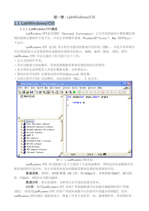
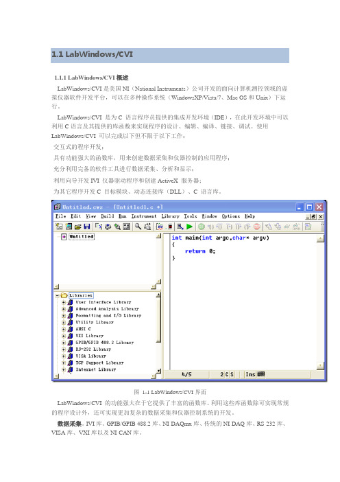
第一章 : LabWindows/CVI1.1 LabWindows/CVI1.1.1 LabWindows/CVI概述LabWindows/CVI是美国NI(National Instruments)公司开发的面向计算机测控领域的虚拟仪器软件开发平台,可以在多种操作系统(WindowsXP/Vista/7、Mac OS和Unix)下运行。
LabWindows/CVI 是为C 语言程序员提供的集成开发环境(IDE),在此开发环境中可以利用C语言及其提供的库函数来实现程序的设计、编辑、编译、链接、调试。
使用LabWindows/CVI 可以完成以下但不限于以下工作:·交互式的程序开发;·具有功能强大的函数库,用来创建数据采集和仪器控制的应用程序;·充分利用完备的软件工具进行数据采集、分析和显示;·利用向导开发IVI 仪器驱动程序和创建ActiveX 服务器;·为其它程序开发C 目标模块、动态连接库(DLL)、C 语言库。
图 1‐1 LabWindows/CVI界面LabWindows/CVI 的功能强大在于它提供了丰富的函数库。
利用这些库函数除可实现常规的程序设计外,还可实现更加复杂的数据采集和仪器控制系统的开发。
数据采集。
IVI库、GPIB/GPIB 488.2库、NI-DAQmx库、传统的NI-DAQ库、RS-232库、VISA库、VXI库以及NI-CAN库。
数据分析。
格式化IO库、分析库以及可选的高级分析库。
GUI库。
使用LabWindows/CVI 的用户界面编辑器可以创建并编辑图形用户界面(GUI),而使用LabWindows/CVI 的用户界面库函数可以在程序中创建并控制GUI。
此外,LabWindows/CVI为GUI 面板的设计,准备了许多专业控件,如:曲线图控件、带状图控件、表头、旋钮和指示灯等,以适应测控系统软件开发的需求,利用这些控件可以设计出专业的测控程序界面。
LabWindows_CVI仪器驱动程序与IVI体系结构
仪器驱动程序 ’ 函数体 ( 内部子例程接口 图# &%+) % , - 接口
仪器驱动程序外部接口模型图
图中各部分的说明: ’ # ( 应用程序 用户开发的用于自动测试的应用程序。 ’ ! ( 交互式开发界面 对于 /012345678 , 9&% 来讲, 交互式开发界 面就是图形化的 /012345678 , 9&% 函数面板。 /012345678 , 9&% 函数面板允许用户通过 /01: 2345678 , 9&% 函数面板交互式的操作特定的仪 器或向应用程序的代码中自动添加仪器驱动函 数的调用。 在 /012345678 , 9&% 函数面板还提供 了对函数的接口的详细说明,帮助程序员理解 每一个函数的作用与使用方法。 ’ $ ( 程序开发接口 程序开发接口是指在高层的应用程序中调 用仪器驱动程序的方法。 在 /012345678 , 9&% 仪 器驱动程序中,仪器驱动程序的软件接口是用 标准的函数调用实现的,与标准的库函数调用 没有什么不同。 ’ . ( 仪器驱动程序 ’ 函数体 ( /012345678 , 9&% 仪器驱动程序是用来控
收稿日期 N #""" O "& O #(
1 > E 协议就可以容易的控制仪器,包括 FG1B、 串行设备或者其它设备。早期的仪器驱动 *71、 程序有很多局限性,用户希望仪器驱动程序是 开放的和可修改的,并且最好是围绕一种标准 来构造驱动程序。 *71 H0.@IH0/J 系统联盟自建立以来一直从 事解决系统级的软件问题,并且为发展已存在 的 仪 器 驱 动 程 序 标 准 做 了 有 效 的 工 作 。 *71 H0.@IH0/J 仪器驱动程序体系结构,综合了已有 的流行的技术, 构造了成功的 8/9:+2;<=3 > ?*1 仪器驱动程序标准。 这些标准使用 *1DC % *+,-./0 123-,.452-/-+<2 D<K-=/,5 C,LM+-5L-.,5 ) 定义的数 据类型来定义所有仪器驱动程序函数的接口。 这些数据类型提高了仪器驱动程序在不同操作 系统和编程语言之间的可移植性。 1*1( 12-500+@52*+,-./0 123-,.452-3)模型将 *71 H0.@IH0/J 模型 向前推进了一步,而且并未导致复杂性的增加 和性能的降低。 1*1 给仪器驱动程序增加了许多 新的重要的特性, 比较重要的有以下几个: % $ ) 状态缓存 只有当 1*1 驱动程序自动缓存仪器的状态, 仪器的状态设置与驱动程序所需要的不同时才 执行仪器 1 > E。这样就消除了许多冗余的命令, 加快了测试的速度。 % # ) 可配置的范围检查 1*1 驱动程序自动范围检查功能检验程序 员给仪器的属性所设置的值是否在有效范围之 内, 为了加快执行速度也可以取消这个功能。 % ! ) 可配置的状态查询 1*1 驱动程序自动状态查询特性在对仪器
初步认识CVI程序设计一个示例

CVI程序设计语言支持标准的控制结构,如顺序、选择和循环等。这些控制结构的使用方式与标准C语言 相同,但CVI提供了更多的工具和函数来简化这些结构的实现。
CVI程序的基本结构
主函数
每个CVI程序都必须包含一个主函数(main()),它是程序的入 口点。主函数可以接受命令行参数,并返回一个整数值作为程
详细描述
CVI程序设计语言在自动化控制领域具有广泛的应用。由于CVI具有高效的性能和实时 性,因此非常适合用于开发需要快速响应和高度可靠性的控制系统。通过使用CVI,开
发者可以轻松地与各种硬件设备进行通信和控制,从而实现自动化生产和管理。
06
CVI程序开发进阶
高级控件和组件的使用
自定义控件
通过继承现有控件或使用第三方控件库,创 建具有特定功能和外观的控件。
控件属性
设置控件的属性,如大小、位置、颜色、字 体等,以满足特定的设计需求。
事件处理
为控件添加事件处理程序,响应用户的操作, 如按钮点击、鼠标移动等。
控件布局
使用布局管理器或手动设置控件位置,实现 界面的合理布局。
多线程和异步编程
线程管理
创建、启动、停止和同步线程,以实现多任务处理。
异步编程
使用回调函数、事件或协程等方式,实现非阻塞性操作。
序的退出状态码。
头文件
CVI程序中经常使用头文件来声明函数原型、定义常量、声 明数据类型等。这些头文件通常以“.h”为扩展名。
源文件
源文件包含程序的实现代码,通常以“.c”为扩展名。每个源 文件可以包含多个函数定义,这些函数可以相互调用以实现程
序的功能。
03
CVI程序设计示例
创建CVI应用程序
创建新项目
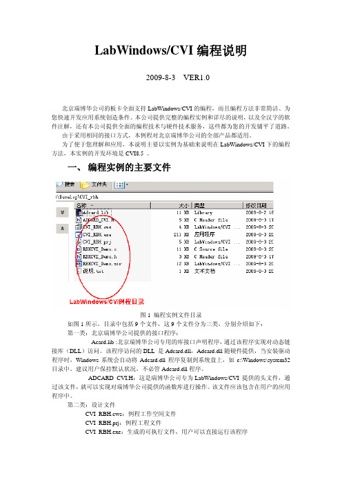
LabWindows_CVI采集卡编程说明
7.
定时器程序
在定时器程序中被调用 //开关量采集命令 void ReadDI(void) { char DiStr[50]; unsigned char Str1[3]; int i; i=Rbh_DI(2,&DIValue[0]);//从驱动程序得到开关量采集结果 //显示开关量采集结果,用十六进制方式表示,每个字节的 8 位,每位代表一个开关量 状态 sprintf (DiStr, "Byte0= %02x, Byte1=%02x", DIValue[0],DIValue[1]); SetCtrlVal (panelhandle, PANEL_DISTR, DiStr); }
//定义采集的参数 int NumBuf;//采集的通道数 int NumSamp; int BegChn; int NumChn; int FrqSamp; int FrqFilter; int AmpGain; //下面的参数从驱动程序中读出 char ADCard_Name[100]; //采集卡名称 int Maxchn; //最大通道数 int LowFreq; //最低的采样频率 int HighFreq; //最高的采样频率 int MinSampNum; //最少的每包采样点数 float VZero; //AD 转换结果的零点 AD 值 float VMax; //AD 转换结果的最大 AD 值 int MaxBinChn; //最大二进制开关量个数
6.
定时器程序
定时器程序是高速连续采集的关键程序,在本程序中显示三个功能: z 高速、连续模拟量采集与曲线显示、数字显示功能; z 开关量采集与现实功能 z 采集状态信号灯控制功能 //定时器功能 int CVICALLBACK TIMER_AD (int panel, int control, int event, void *callbackData, int eventData1, int eventData2) { int i; switch (event) { case EVENT_TIMER_TICK: if(!FlagStartAD)return 0; //如果定时器没有启动就退出 i=ReadADResult(); //采集模拟量 ReadDI(); //开关量采集 //下面控制 LED 灯,当启动采集时,该状态灯一亮一灭 if(swTimer==0){ swTimer=1; //亮灭标志置 1 SetCtrlVal(panel, PANEL_LED_AD, 0);//标志灯亮 }else { swTimer=0;//亮灭标志清零 SetCtrlVal(panel, PANEL_LED_AD, 1);//标志灯灭 } break; } return 0; }
CVI学习资料
第三章LabWindows/CVI 编程环境LabWindows/CVI开发环境有以下三个最主要的窗(window)与函数面板(Function Panel):·项目工程窗(Project Window)·用户接口编辑窗(User Interface Editor window)·源代码窗(Source window)下面就会对以上三个窗及函数面板作详细的介绍.项目工程窗(Project Window)一个项目工程窗(Project Window)如下图所示:在项目工程窗中列出了组成该项目工程所有的文件,项目工程窗中的个菜单项功能如下:File : 创建,保存或打开文件.可以打开以下文件:项目工程文件(*.Prj)源代码文件(*.c),头文件(*.h)以及用户接口文件(*.uir).Edit: 在项目工程中添加或移去文件.Build: 使用LabWindows/CVI 编译链接器.Run: 运行一个项目工程.Windows: 用来访问某个已经打开的窗,例如:用户接口编辑窗,源代码窗… .Tools: 运行向导(wizard)或者你添加到Tools菜单中的一些工具.Options: 设置LabWindows/CVI 的编程环境.Help: LabWindows/CVI 在线帮助及Windows SDK 的函数帮助.工程项目文件显示了所列文件的状态,其各项的含义如下图所示:文件名这个标志是指源代码最后修改该文件文件是否是打开的的日期时间S是指该文件已经修C是指运行该文件之O是指你可以让该文件I 是指这是一个改过了,请保存该文件前必须先经过编译编译而无需debugging 仪器驱动程序如果你想进一步了解项目工程窗(Project window)细节请使用在线帮助.请选择:Help>>CVI Library>>Related Help…Online Manuals For LabWindows/CVI请查阅LabWindows/CVI User Manual Chapter 3 Project window. 第二节用户接口编辑窗(User Interface Edit window)图形用户接口编辑窗是用来创建,编辑GUI(Graph Uer Interface)的.一个用户接口至少要有一个面板(Panel)以及在面板上的各种控件元素(Control Element).图形用户接口编辑窗为你提供了非常快捷的创建,编辑这些面板和控件元素的方法,可以让你在短时间里创建出符合你要求的图形界面.一个图形用户接口编辑窗就如下图所示,下面我们就详细讲讲图形用户接口编辑窗各菜单项的功能:File: 创建,保存或打开文件.Edit: 可用来编辑面板或控件元素.说明:其实我们直接用鼠标双击我们想要编辑对象即可(就象编制FisrtSample5 [资料1]LabWindows/CVI基础教程中修改面板和四个按扭那样).Creat: 可用来创建面板和各种控件元素.说明:其实我们只需在Panel上点击鼠标右键,便会弹出一个快捷菜单,选择你所想创建的对象即可(就象编制FisrtSample 时创建Graph和四个Button 那样). View: 当创建多个面板后就可用该项来查看想要看的面板.Arrange: 用来调节各个控件元素的位置与大小.Code: 产生源代码,以及选择你所需的事件消息类型.Run: 运行程序.Library: 函数库.说明:我们将在后面详细的介绍LabWindows/CVI的函数库. Tools: 一些你可使用的工具项.Windows: 用来访问某个已经打开的窗,例如:项目工程窗,用户接口编辑窗,源代码窗… .Options: 设置用接口编辑窗的编辑环境.Help: LabWindows/CVI 在线帮助及Windows SDK 的函数帮助.说明:在用户接口编辑窗中有一快捷菜单是非常有用的,当你把鼠标指在某一控件元素上点击右键后便弹出一快捷菜单,通过该菜单你可以生成回调函数以及查看回调函数,而无须你再切换到源代码窗后再查看.这是一个大家以后在编程中要常用到的技巧,请掌握.图形用户接口编辑窗中还有四个模式选择按扭,现介绍如下:当该按扭被按下后,你可以操作面板上的控件,同时在图形用户接口编辑窗的右上角上来观察面板上的事件消息.在这种模式下你可以创建,编辑面板和控件元素以及修改它们的属性. 在这种模式下你可以直接修改控件元素的名字,标签等文字相关方面的东西. 在这种模式下你可以直接修改面板,控件元素的颜色.先把鼠标方在你所想修改颜色的对象上,点击右键便会弹出一个选色对话框,选择你所想要的颜色后点击后即可. 在图形用户接口编辑窗中Panel 的灰色区域中单击鼠标右键,便会弹出一个快捷菜单如下所示:说明:请读者用鼠标点击各项自己看一看,在这里就无须作者多言.如果你想进一步了解用户接口编辑窗(User Interface Edit window)细节请使用在线帮助.请选择:Help>>CVI Library>>Related Help…Online Manuals For LabWindows/CVI请查阅LabWindows/CVI User Manual Chapter 4 User Interface Edit window源代码编辑窗(Sourse window)你可以在源代码编辑窗中开发你的C 语言代码文件.例如:添加,删除,插入函数等编程所需的基本编辑操作.但是LabWindows/CVI 又有其独特的简捷快速的开发,编辑工具,可以让你在短时间内完成一个较复杂的C程序代码的开发.一个源代码编辑窗(Source window)就如下图所示,下面我们就详细讲讲源代码编辑窗中各菜单项的功能:File: 创建,保存或打开文件.Edit: 可用来编辑源代码文件.View: 设置源代码编辑窗的风格等功能.Build: 编译文件以及编译设置.Run: 运行程序.Instrument: 装入仪器驱动程序.Library: 函数库.Tools: 一些你可使用的工具项.Windows: 用来访问某个已经打开的窗,例如:项目工程窗,用接口编辑窗,源代码窗… .Options: 设置用接口编辑窗的编辑环境.Help: LabWindows/CVI 在线帮助及Windows SDK 的函数帮助.说明:在编程中有一快捷菜单是非常有用的,当你把鼠标指在某一函数上点击右键后便弹出一快捷菜单,通过该菜单你可以查看回调函数以及与该函数对应控件元素.这是一个大家以后在编程中要常用到的技巧,请掌握.第四节函数面板(Fuction Panel)在LabWindows/CVI 编程环境下,当你想在源程序某处插入函数时,你只需从函数所在的库中选择该函数后便会弹出一个与之对应的函数面板,你所做的就是:填入该函数所需的参数后完成插入即可.而且更为方便的是:若参数是一你以有的常量或变量,你只需点击常量或变量工具按扭后选择你所需的量即可;若参数是一变量,你直接可声明该变量而无须再切换至源代码窗.下面我们就谈谈这些在LabWindows/CVI中可以加快你编程的技巧. 一个函数面板如下图所示:这是FirstSample中产生一个正弦波的函数其中SinePattern项是用来装正弦波的数组,我们在程序中使用数组Wave[512] 来装正弦波的.当我们在SinePattern项填入Wave后,由于Wave是一变量,所以我们需要声明该变量:让鼠标指在Wave上然后点击工具条中的声明变量按扭后, 便弹出一个声明变量对话框即可声明该变量为局域变量或为全局变量.作者:立士心 2005-10-4 15:29 回复此发言--------------------------------------------------------------------------------6 [资料1]LabWindows/CVI基础教程当你所填参数是一以有的常量或变量,你只需点击选择常量或变量工具按扭后选择你所需的量即可,下面就介绍该技巧:上图是FirstSample中把数组Wave中的正弦波画到Graph上去的PlotWaveform函数.其中,Control ID 项所填的是程序中用来标识GUI 中控件元素的常量,该常量是由LabWindows/CVI自动在头文件中预定义的(你可以打开头文件看看).故当我们填入该常量时只需将鼠标放在Control ID项的文本框中然后用鼠标点击工具条中的选择属性或UIR常量按扭后, 便弹出一个选择属性或UIR常量对话框,选择你所需的常量或属性即可.Panel Handle 是程序运行开始时UIR的句柄,是由LabWindows/CVI 自动生成的是一变量;Number of Points 项需填的是512,这正是我们在声明Wave时已用过的;Y Array 项所填的是我们已经声明过的变量——数组Wave;故当我们填入以上各项时只需将鼠标放在对应项下文本框中,然后用鼠标点击工具条中的选择变量按扭后, 便弹出一个选择变量对话框,选择你所需的变量Wave即可.当你填完函数的参数后,点击插入按扭后即可完成函数的插入,而无须再选择菜单中的插入命令.以上这些都是加快你编程的技巧,这些技巧你以后编程时是会非常频繁使用的.而这些也正是LabWindows/CVI 开发环境所独具的加快你编程速度的特色.说明:当你的鼠标落在工具条按扭上时,计算机会自动的显示该工具按扭的功能.请你使用上面所讲技巧重新编制FirstSample,我相信你将会有新的收获.当你对函数中的某个参数有不明白的时候,你只须将鼠标置于该项的文本框中点击鼠标右键后便会出现对此参数说明的在线帮助,这一技巧在编程中是非常有帮助的.如果你想进一步了函数面板(Function Panel )细节请使用在线帮助.请选择:Help>>CVI Library>>Related Help…Online Manuals For LabWindows/CVI请查阅LabWindows/CVI User Manual Chapter 6 Using Function Panels第四章LabWindows/CVI 的函数库(Library)LabWindows/CVI 其强大功能的所在就是基于其非常丰富的库函数.LabWindows/CVI 所提供的库函数从用户图形界面,数据采集,数据分析,仪器控制… 到现在Internet时代的TCP.所以说LabWindows/CVI 在测量领域成为先锋的同时又与当前时代的新科技保持了同步.下面我们就来谈谈LabWindows/CVI 的函数库,我们把LabWindows/CVI 的函数库分为了五个大的方面,各个方面又分成了不同的小类:·数据采集方面(Data Acquisition),7个库:Instrument Library: 仪器驱动库GPIB/GPIB 488.2 Library: 仪器控制函数库Data Acquisition Library: 数据采集函数库Easy I/O for DAQ : 易用的数据采集函数库RS 232 Library : RS 232 库VISA Library : VISA 库VXI Library : VXI库·数据分析方面,两个库:Formatting and I/O Library : 格式化以及输入输出库Analysis Library: 分析库或者Advanced Analysis Library: 高级分析库·数据显示方面:User Interface Library : 用户接口库说明: 用户接口库中提供了许多用于与面板上各种控件元素打交道的函数,通过这些函数你可以非常容易的把一个采集来的波形画到Panel 的Graph上或删除Graph 上已画的图形;得到Panel上某个控件元素的数值以及把某个数值写到Panel上的某个控件元素上去(亦就是改变该控件元素的值);修该Panel上控件元素的属性.总之,你只有熟练掌握了用户接口库函数后才能使你创建的用户图形界面正正的动起来,该库是初学者应迅速熟悉的库.·网络,通信与数据交换方面,四个库:DDE Library : 动态数据交换库TCP Library: TCP库Active X Automation Library: Active X自动化库DataSocket Library: DataSocket库·其它方面:ANSI C Library: 标准C 库如果你想进一步了解LabWindows/CVI 函数库(Library)细节请使用在线帮助.请选择:Help>>CVI Library>> Library Help中你感兴趣的库作者:立士心 2005-10-4 15:29 回复此发言-------------------------------------------------------------------------------- 7 [资料1]LabWindows/CVI基础教程通过本部分的学习,你是否已经掌握□LabWindows/CVI 程序设计步骤及程序的运行机制.三个主要窗的基本操作.在用户接口编辑窗中用快捷方式生成或查看回调函数,在源代码窗中用快捷方式返回到函数面板或对应控件元素等编程中所需的快捷操作.在函数面板上声明变量,选择变量或常量,插入函数等快捷操作.LabWindows/CVI 库的构成及其在编程中适用的方向.第四部分CVI 中数据采集的应用通过前两部分的学习,读者应该已掌握了LabWindows/CVI程序设计的基本步骤,思路以及编程环境.本部分将在前两部分的基础上讲解LabWindows/CVI中的数据采集,并在讲解的过程中编制一个程序:EeasyIOSample .请读者确保自己已经安装了Daq驱动,否则你会找不到例子中要用到的函数.Easy IO 库中数采函数的应用本章我们将使用Easy IO 库中的数采函数来编制一个真正能用于实际工作中的数据采集程序EasyIOSample.我们程序运行时的界面如下图所示:其中各控件元素的功能说明如下:ChannelSrting 项是一字符串控件,我们通过该项来设置采集数据的通道(数采路径).我们把该项缺省设置为:daq::1!(0)其意思是指:采集设备(device)1的0通道(channel).其中设备号正是你在Measurement &Automation 中所看到的对应于数采板的编号.在数采停止时,该项是可以修改的.daq::1!(0) 这段字符串是NI 数采通道的语法表示,具体说明如下: daq::1!(0,2,5) 是指采集设备1的通道0,2,5.daq::1!(2:6)是指采集设备1的通道2,3,4,5,6.ScanRate项是一数字控件,我们通过该项来设置扫描速率,其缺省设置为1000Acquire/Stop项是一开关控件,我们通过该开关来控制数据采集的开始与停止.Clear项是一按扭,当我们按下该按扭后即可清除Acquire Wave上所画的波形.Quit项是一按扭,当我们按下该按扭后,退出程序.Acquire Wave项是一波形显示控件,我们所采集的数据正是通过该控件来显示的.现在我们就开使创建该程序.首先按下面步骤起动CVI:开始>>程序>>National Instrument CVI>>CVI IDE或者直接从桌面起动CVI 的快捷方式,双击桌面National Instrument CVI 图标当LabWindows/CVI打开后你就会见到如下所示的项目(Project)窗,里面装的正是我们上次创建的FirstSample.prj:选择:File>>New>>Project(*.prj)…便会弹出一个对话框,如下所示:询问你是否移走当前的项目工程,点击OK按扭,确定移走后又会弹出一个对话框如下所示:询问你转移该项目的选项,全选之后点击OK按扭后,便会弹出一个新的项目工程窗.第一节创建图形用户界面从Project窗中选择:File>>New>>User Interface(*.uir)…创建一个用户图形接口文件(*.uir).下图就是本程序应该创建的UIR界面:请按下面步骤创建下列控件元素以及修改其属性:创建一个string ,修改其属性如下图所示:创建一个Numeric, 修改其属性如下图所示:创建一个BinarySwitch, 修改其属性如下图所示:创建一个Timer控件, 修改其属性如下图所示:请你确保Control Settings中Enable项前的矩形框是空的,因为我们将AI Timer的初始状态设置为非运行状态.说明:Timer控件是一我们在编程时常用到的控件,当程序运行时图形用户界面上是看不到Timer控件的.当你设置Timer有回调函数时,计算机会每隔固定的时间调用一次Timer的回调函数.该时间间隔你是可以在Edit Timer 窗中Contro Settings的Inteval(seconds)项中设定的.本程序设定时间间隔为0.1秒,也就是说:当程序运行时,每隔0.1 秒AITimerCallback( )函数就会被调用一次.创建一个Graph控件, 修改其属性如下图所示:创建两个Command控件, 修改它们属性分别如下两图所示:最后修改Panel的属性如下图所示:创建好各控件元素后,将它们按下图所示排放好各自的位置:说明:由于程序运行时,AI Timer 控件并不在界面中显示,故AI Timer 的位置你可以随作者:立士心 2005-10-4 15:29 回复此发言--------------------------------------------------------------------------------8 [资料1]LabWindows/CVI基础教程意放置.选择:File>>Save 保存UIR文件,命名为EasyIOSample.uir.第二节产生程序代码与添加函数代码从用户图形界面窗口中选择:Code>>Generate>>All Code…产生源程序框架.其源程序代码中需要你注意的如下:当某一行字符是蓝色时是指该行代码是需要我们添加上去的.为了作者讲解函数功用的方便,作者按照顺序把插入的函数编了号,标注在该函数的顶头.#include#include#include#include "EasyIOSample.h"static int panelHandle;static long AiTask;int main (int argc, char *argv[]){if (InitCVIRTE (0, argv, 0) == 0)return -1; /* out of memory */if ((panelHandle = LoadPanel (0, "EasyIOSample.uir", PANEL)) >User Interface>>Controls/Graph/Strip Chart>>General Functions>>Get Control Value.GetCtrlVal (panelHandle, PANEL_CHANNEL_STRING, ChanString) 使用该函数我们可以得到字符串ChannelString的值(请在该函数面板中声明局部字符串变量ChanString).插入该函数时请选择:Library>>User Interface>> Controls/Graph/Strip Chart>>General Functions>>Get Control Value.GetCtrlVal (panelHandle, PANEL_SCANRATE, &ScanRate) 使用该函数我们可以得到数字量ScanRate的值(请在该函数面板中声明局部双精度变量ScanRate).插入该函数时请选择:Library>>User Interface>> Controls/Graph/Strip Chart>>General Functions>>Get Control Value.nidaqAICreateTask (ChanString, kNidaqWaveformCapture, &NumChan, &AiTask) 使用该函数我们可以创建一个模入采样任务AITask(请在该函数面板中声明全局整型变量AITask), 同时该函数根据ChanString可以返回一个表示该采样任务共有多少个通道的值NumChan(请在该函数面板中声明局部整型变量NumChan).插入该函数时请选择:Library>>EasyIO For DAQ>>Analog Input >>Intermediate Analog Input>>AI Creat Task(Required).nidaqAIConfigScanClockRate (AiTask, ScanRate, &ActScanRate) 使用该函数我们可以设置采样的扫描速度ScanRate并且通过ActScanRate返回采样的实际扫描速度(请在该函数面板中声明局部双精度变量ActScanRate).插入该函数时请选择:Library>>EasyIO For DAQ>>Analog Input >>Intermediate Analog Input>>AI Config Timing…>>AI Config Scan Clock Rate…nidaqAIConfigBuffer (AiTask, 2000000, kNidaqContinuous) 使用该函数我们可以设置采样缓冲为2M(即2000000).插入该函数时请选择:Library>>EasyIO For DAQ>>Analog Input >>Intermediate Analog Input>>AI Config Buffer…nidaqAIStart(AiTask)使用该函数我们可以启动数据采集任务.插入该函数时请选择:Library>>EasyIO For DAQ>>Analog Input >>Intermediate Analog Input>>AI Start (Required)…SetCtrlAttribute (panelHandle, PANEL_TIMER, ATTR_ENABLED, 1) 我们在UIR 中将AI Timer的属性设置为非运行状态,现在通过该函数将AI Timer 属性设置为Enable 即从现在开始AI Timer 开始运行,每隔固定的时间间隔调用一次AITimerCallBack( )函数.插入该函数时请选择:Library>>User Interface>> Controls/Graph/Strip Chart>>General Functions>>Set Control Attribute...SetCtrlAttribute (panelHandle, PANEL_TIMER, ATTR_ENABLED, 0) 使用该函数我们可以让控件AI Timer停止工作.插入该函数时请选择:Library>>User Interface>> Controls/Graph/Strip Chart>>General Functions>>Set Control Attribute...nidaqAIStop (AiTask) 使用该函数我们可以停止采样任务.插入该函数时请选择:Library>>EasyIO For DAQ>>Analog Input >>Intermediate Analog Input>>AI Stop (Required)…nidaqAIDestroyTask (AiTask) 使用该函数我们可以取消采样任务.插入该函数时请选择:Library>>EasyIO For DAQ>>Analog Input >>Intermediate Analog Input>>AI Destroy Task(Required)…作者:立士心 2005-10-4 15:29 回复此发言--------------------------------------------------------------------------------9 [资料1]LabWindows/CVI基础教程DeleteGraphPlot(panelHandle,PANEL_GRAPH,-1,VAL_IMMEDIATE_DRAW)使用该函数我们可以清除Graph控件上所画的图形.插入该函数时请选择:Library>>User Interface>>Control/Graph/Strip Chart>>Graph and Strip Chart>>Graph Plotting and Deleting>>Delete Graph Plot…nidaqAICheck (AiTask, &AcqState, &AcqBacklog)使用该函数我们通过返回AcqState参数的值可得知采样过程的状态;通过返回AcqBacklog参数的值可得知所采样以放在缓冲中的有多少个点我们未读取(请在该函数面板中声明局部长整型变量AcqState与AcqBacklog).插入该函数时请选择:Library>>EasyIO For DAQ>>Analog Input >>Intermediate Analog Input>>AI Destroy Task(Required)…nidaqAIRead (AiTask, ChanString, AcqBacklog, -1.0, AcqData) 使用该函数我们可以将缓冲中未读的数据读到数组AcqData中(请在该函数面板中声明局部双精度数组变量AcqData[10000]).插入该函数时请选择:Library>>EasyIO For DAQ>>Analog Input >>Intermediate Analog Input>>AI Read (Required)…DeleteGraphPlot(panelHandle,PANEL_GRAPH,-1,VAL_IMMEDIATE_DRAW)使用该函数我们可以清除Graph控件上所画的图形.插入该函数时请选择:Library>>User Interface>>Control/Graph/Strip Chart>>Graph and Strip Chart>>Graph Plotting and Deleting>>Delete Graph Plot…PlotWaveform(panelHandle,PANEL_GRAPH,AcqData,AcqBacklog,VA L_DOUBLE, 1.0, 0.0, 0.0, 1.0, VAL_THIN_LINE, VAL_EMPTY_SQUARE, VAL_SOLID, 1, VAL_RED) 使用该函数我们可以将读到数组AcqData中的数据(AcqBacklog个数据)画到控件Graph 上.插入该函数时请选择:Library>>UserInterface>>Control/Graph/Strip Chart>>Graph and Strip Chart>>Graph Plotting and Deleting>>Plot Waveform ..下面我们将仔细讲解当Acquire/Stop开关被扳上(下)去后程序的运行过程.程序流程图如下:GetCtrlVal (panelHandle, PANEL_ACQUIRE, &Value)// 得到Acquire/Stop二进制开关的值Value= 0 SetCtrlAttribute ( )Value // 让AITimer 停止工作=1GetCtrlVal (panelHandle, PANEL_CHANNEL_STRING, ChanString) // 从UIR上字符串控件ChannelString得到采样通道设置GetCtrlVal (panelHandle, PANEL_SCANRATE, &ScanRate)// 从UIR上数字量控件ScanRate得到采样扫描速率设置nidaqAICreateTask ( ) // 创建采样任务nidaqAIConfigScanClockRate ( ) // 设置扫描速率nidaqAIConfigBuffer ( ) // 设置缓冲区大小nidaqAIStart( ) // 采样任务开始SetCtrlAttribute ( ) // 让AITimer 开始工作注意:让AITimer开始工作其实也就是每隔一定的时间间隔调用一次AITimerCallback( )函数每隔0.1秒AITimerCallback( ){nidaqAICheck ( ) // 检查采样过程中缓冲的状态nidaqAIRead ( ) // 从缓冲中读取数据DeleteGraphPlot( ) // 先清除Graph上已有的图形PlotWaveform( ) // 把从缓冲中读到的数据画到Graph上}AITimer 是No否停止工作YesnidaqAIStop ( ) // 停止采样任务nidaqAIDestroyTask ( ) // 取消采样任务到此为止我们已经完成本章的学习,有些内容需要读者反复研读以理解LabWindows/CVI在数据采集中的应用,该程序亦可作为读者进一步学习LabWindows/CVI的敲门砖.通过本部分的学习,你是否已经掌握□ LabWindows/CVI 中数采程序设计步骤及程序的运行机制.巩固在用户接口编辑窗中用快捷方式生成或查看回调函数,在源代码窗中用快捷方式返回到函数面板或对应控件元素等编程中所需的快捷操作.巩固在函数面板上声明变量,选择变量或常量,插入函数等快捷操作.后记通过对本书的学习,相信读者已经基本掌握了LabWindows/CVI编程基本操作.希望读者在初学时一定要注意程序设计的思想,而不必要过多的去抠一些细节问题.下面谈谈如何进一步学习与使用LabWindows/CVI的一些捷径.在LabWindows/CVI安装目录下的Samples文件夹下有非常多的例程,请读者选择自己感兴趣类别的例子打开后看看,并且读者在开发项目时直接将这些例子中的一些程序拷贝到自己的程序中去.这样做,不但能减少开发时间并且减少程序的出错机率,这是一项实在值得读者注意的技巧.怎么看懂例程当读者打开一个例子后,通过查看控件对应回调函数,返回函数对应的函数面板以及查看函数参数在线帮助,你就可以通过这些方法看懂例程.从而即可以学习函数的使用也能够明白编制某类别程序的基本思想.下面所列的是在使用LabWindows/CVI开发程序时值得一看的书目:bWindows/CVI在线帮助中CVI Library>>Online Manuals For LabWindows/CVI 中的一些程序设计参考书.2 .读者若装有NI公司的数采卡,则在装DAQ驱动后读者会在在开始>>程序>>National Instruments DAQ>>Documents中找到下面这本书:NI-DAQ User Manual for PC Compatibles 该书详细得介绍了怎样使用DAQ函数,实在是值得一读的一本书.。
labwindowscvi实例
labwindowscvi实例LabWindows/CVI是一款适合工程师和科学家开发数据采集、控制和分析应用的视窗程序编程环境。
它提供了高效的开发工具和广泛的函数库,让用户可以快速开发出高质量的应用程序。
在本文中,我们将介绍LabWindows/CVI的一些常见功能和实例。
希望本文能够帮助初学者更好地理解和学习这款软件。
LabWindows/CVI的环境LabWindows/CVI是一个Windows环境下的程序,它提供了一个类似于C语言的集成开发环境。
用户可以使用它来创建GUI应用、控制器和数据采集应用。
用户也可以使用它来运行时的调试和测试等操作。
创建GUI应用1. 创建一个新项目:选择文件、新拉,选中创建一个新的项目。
在创建新项目的对话框中,选择GUI应用程序,并指定项目名称和所需的其他信息。
2. 设计应用程序界面:在LabWindows/CVI中开发GUI应用程序时通常使用模板来加速开发。
模板包括经典的样板应用程序、菜单、对话框、工具栏等。
3. 添加控件:将各种工具添加到在步骤2中创建的界面中。
在LabWindows/CVI中,可以使用Ctrl和Shift键选择一个或多个控件或元素。
4. 定义控件属性:对于每个添加的控件,您需要定义它的属性。
例如,如果您添加一个按钮,则需要定义它的外观、行为和代码。
您可以通过代码或LabWindows/CVI屏幕上的属性列表来定义这些属性。
5. 添加源码:在定义应用程序界面和控件之后,您需要添加与应用程序功能相关联的代码。
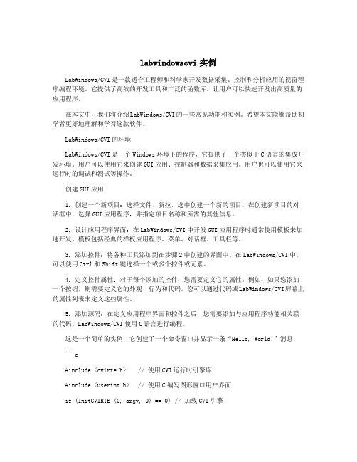
LabWindows/CVI使用C语言进行编程。
这是一个简单的实例,它创建了一个命令窗口并显示一条“Hello, World!”消息:```c#include <cvirte.h> // 使用CVI运行时引擎库#include <userint.h> // 使用C编写图形窗口用户界面if (InitCVIRTE (0, argv, 0) == 0) // 加载CVI引擎return -1;// 创建一个新的用户界面窗口panelHandle = LoadPanel (0, "example.uir", 1, PANEL);// 将消息更新到文本框对象SetCtrlVal (panelHandle, PANEL_TEXTBOX, message);// 显示窗口DisplayPanel (panelHandle);// 退出程序RunUserInterface ();// 释放资源DiscardPanel (panelHandle);return 0;}```数据采集应用在数据采集应用中,可以使用设备接口板或直接与计算机的串行或USB接口通信。
cvi教程

第十讲 数据库应用程序设计
2. 结构化查询语言(Structured Query Language, SQL)
• • 利用SQL即可实现对数据库的各种交互操作,SQL是关 系型数据库管理系统的标准语言。 一些经常用到的SQL命令:
2015/12/11
CREATE TABLE—创建一个新的表,指定每列的名字和数据类 型。 SELECT—回收表中符合特定条件的所有行。 INSERT—将一个新的记录添加到表中,接着可以对行赋值。 UPDATE—改变指定行里符合特定条件的所有列的值。 DELETE—删除符合特定条件的所有行。
2015/12/11 12/15
第十讲 数据库应用程序设计
• 步骤4. 断开SQL连接
SQL操作结束后,应断开SQL连接来释放系统资源。 这个步骤在任何方向上取值时都是特别重要的,它可 保证工具包适当地关闭并删除临时登记文件。
• 步骤5. 断开数据库
全部数据库操作结束时,应断开通过SQL建立的数据 库连接,以适时地释放系统资源。
• 必须对使用的ODBC驱动器进行注册。 • 用控制面板上的ODBC管理器图标注册并配置驱 动器使其成为对应用可用的数据源。 • 举例
2015/12/11
7/15
第十讲 数据库应用程序设计
5. Table控件
• 利用表格控件可以输入或浏览数据。表格中每 个单元格均可显示数字型数据、文本型数据或 图形数据。
1. 数据库的基础知识
• 数据库由组织好的数据集组成。虽内在细节有 所不同,但最新的数据库管理系统(DBMS)都将 数据存为表的形式。 • 表的结构通过记录和字段构成的二维形式来实 现(其中,记录又称为行,字段又称为列)。 • 数据库中每个表必须有一个唯一的名字。类似 地,表中每个字段必须有一个唯一的名字。
cvi培训讲义
37/78
5、常用函数
7、数据格式化(Libraries->ANSI C->String Handling->..) (Libraries->ANSI C->General Utilities>..) (Libraries->Formatting and I/O Library->Data Formatting->..)
8/78
4、构建一个简单程序
1、建立工程文件 2、创建用户界面文件,设置面板 3、向面板添加控件,设置控件属性 4、生成源代码文件 ,生成Main函数及各控件回 调函数,编写代码 5、运行和调试程序 6、生成可执行文件和发布文件
(演示:创建一个工程文件,演示各项操作)
9/78
二、基础篇
36/78
5、常用函数
6、字符串操作(Libraries->ANSI C->String Handling->..)
strlen 获取字符串的长度 strcpy, strncpy 字符串拷贝(全部,前n个字符) strcmp, strncmp, stricmp字符串比较(全部,前n个字 符,不区分大小写比较) strcat, strncat 字符串连接(全部,前n个字符) strchr 在字符串中查询某个字符 strstr 在字符串中查询字符串 ……
21/78
1、基本控件的使用及编程
数字图控件(Digital Chart)
22/78
1、基本控件的使用及编程
定时器控件(Timer)
画布控件(Canvas)
23/78
1、基本控件的使用及编程
cvi培训讲义资料

21/78
1、基本控件的使用及编程
数字图控件(Digital Chart)
22/78
1、基本控件的使用及编程
定时器控件(Timer)
画布控件(Canvas)
23/78
1、基本控件的使用及编程
分隔栏控件(Splitter)
24/78
1、基本控件的使用及编程
分页控件(Tab)
25/78
1、基本控件的使用及编程 2、弹出式面板 3、创建菜单 4、文件的读写操作 5、常用函数
10/78
1、基本控件的使用及编程
数值型(Numeric):数值控件、颜色选择控件、 数值滑动条等。
11/78
1、基本控件的使用及编程
文本型(Text):字符串控件,文本信息,文本 框。
12/78
1、基本控件的使用及编程
3、CVI的开发环境
工作空间窗口: 工程目录区:左上角,显示工程架构 函数目录区:左下角,显示函数库和仪器库目录。双击 函数名,即可打开对应的函数面板。 窗口区:右半部分,编辑用户界面、源代码及函数面板。 输出区:右半部下方,显示编译、运行及源代码等的错误 信息。 运行区:右半部下方,显示变量、监视、内存等信息。
表格控件(Table)
18/78
1、基本控件的使用及编程
图形控件(Graph):曲线图控件、带状图控件、 数字图控件
曲线图控件(Graph)
(演示: ..\LabWindows\3\graph)
19/78
1、基本控件的使用及编程
带状图控件(Strip Chart)
20/78
1、基本控件的使用及编程
LabWindowsCVI入门之第一章:LabWindowsCVI开发环境
1.1 LabWindows/CVI1.1.1 LabWindows/CVI概述LabWindows/CVI是美国NI(National Instruments)公司开发的面向计算机测控领域的虚拟仪器软件开发平台,可以在多种操作系统(WindowsXP/Vista/7、Mac OS和Unix)下运行。
LabWindows/CVI 是为C 语言程序员提供的集成开发环境(IDE),在此开发环境中可以利用C语言及其提供的库函数来实现程序的设计、编辑、编译、链接、调试。
使用LabWindows/CVI 可以完成以下但不限于以下工作:·交互式的程序开发;·具有功能强大的函数库,用来创建数据采集和仪器控制的应用程序;·充分利用完备的软件工具进行数据采集、分析和显示;·利用向导开发IVI 仪器驱动程序和创建ActiveX 服务器;·为其它程序开发C 目标模块、动态连接库(DLL)、C 语言库。
图1-1 LabWindows/CVI界面LabWindows/CVI 的功能强大在于它提供了丰富的函数库。
利用这些库函数除可实现常规的程序设计外,还可实现更加复杂的数据采集和仪器控制系统的开发。
数据采集。
IVI库、GPIB/GPIB 488.2库、NI-DAQmx库、传统的NI-DAQ库、RS-232库、VISA库、VXI库以及NI-CAN库。
数据分析。
格式化IO库、分析库以及可选的高级分析库。
GUI库。
使用LabWindows/CVI 的用户界面编辑器可以创建并编辑图形用户界面(GUI),而使用LabWindows/CVI 的用户界面库函数可以在程序中创建并控制GUI。
此外,LabWindows/CVI为GUI 面板的设计,准备了许多专业控件,如:曲线图控件、带状图控件、表头、旋钮和指示灯等,以适应测控系统软件开发的需求,利用这些控件可以设计出专业的测控程序界面。
网络和进程间通信库。
cvi教程
c. 将 Label 项改为 Acquire
说明:通过这种方法可以修改按扭名字,Acquire 中 A 字母前有下画线,是指可
以通过 Alt + A 即可达到按下该按扭的效果(即热键)。
从该菜单中选择:Command Button>>Square Command Button
泛华测控
电话:010-62628052 至 62628055(共四线),传真:010-62628056
第6页便会创建一个方形的按扭。 由于本程序总共需要三个按扭,所以按照上面的步骤再创建两个方形按
或者直接从桌面起动 CVI 的快捷方式,双击桌面 National Instrument CVI 图标
当 LabWindows/CVI 打开后你就会见到如下所示的一个空的项目(Project) 窗:
第一步:创建用户界面
创建控件元素: 从 Project 窗中选择:File>>New>>User Interface(*.uir)…创建一个用户
File 菜单,然后选择 Page Setup 项,最后从弹出的对话框中选择 Options 项。
“说明:通过这种方式你可以修改 Panel 顶端所显示的名字。”
该种字体所写的文字是值得读者注意并记忆的内容。
“
”
该椭圆形框所框住的内容是读者需修改的地方。
泛华测控
电话:010-62628052 至 62628055(共四线),传真:010-62628056
第 10 页
北京中科泛华测控技术有限公司
a. 将 Constant Name 项改为 ACQUIRE
Anritsu LabWindows CVI 基于 IVI 的设备驱动开发方法说明书
IVI State Caching for Groups of AttributesbyIan DeesApplication Software EngineerAnritsu CompanyCategory:TelecomProducts Used:LabWindows™/CVIInstrument Driver Development WizardPCMCIA-GPIB cardThe Challenge:Write an instrument driver capable of caching the values of multiple attributes that are set by the same command. The driver should avoid sending redundant command strings to the instrument, but must also make sure the instrument always has the correct values.The Solution:Using the advanced features of LabWindows/CVI, create shared read and write callback functions, which decide when to send commands to the instrument based on a set of hidden state variables.IntroductionAnritsu is using LabWindows/CVI to write an Interchangeable Virtual Instruments (IVI) driver for computer-based control of Optical Spectrum Analyzers. One of IVI’s benefits is state caching, through which the driver optimizes performance by remembering the state of the instrument. This feature is difficult to implement for some instrument attributes, which can only be accessed by complex commands that set a group of attributes at once. Anritsu and National Instruments collaborated on an innovative solution, which is able to deliver the performance boost of state caching even in difficult cases when a single command sets many attributes.Many Attributes Sharing One CommandWhen a command sets two attributes at once, the Instrument Driver Developers Guide recommends considering one of them to be “dominant” (2-20). When the driver writes the dominant attribute, it picks a reasonable default value for the subordinate one. This method works well for attribute pairs, but larger commands complicate the picture. Imagine a command that sets five attributes at once. We would have to select a dominant attribute, a “second-place”attribute, a “third-place” attribute, and so forth. For each combination of attributes one through four, we would need to choose a default value for the fifth. The attributes would always have to be set in the same order, lest one default value overwrite another.National Instruments Driver Support engineer Edward Zhu recommends a new approach: create an integer attribute representing the state of the entire group. This “state attribute” is hidden: the user must not be able to put the driver into an incorrect state. The IVI engine cannot cache this variable, because the write callback must be called every time the state attribute is changed. Both properties are easy to set in LabWindows/CVI (Figure 1).Figure 1: Configuring the State AttributeThe state attribute can have one of four values: “1 means no updates (instrument I/O) required and defer all future updates, 2 means future updates required, 3 means update now, and 4 is the do nothing state.” (Zhu) Figure 2 shows how our driver will manage the attributes based on the state attribute.Figure 2: State DiagramTo manage the transitions between states, we’ll define three callback routines:•The shared read callback is called by the IVI engine whenever a user-level attribute is read. The driver simply has to “do an instrument I/O, parse the data string, and update the cached values of all the attributes accordingly” (Zhu).•The shared write callback is called when an attribute is changed. This function sets the state attribute to inform the driver that the values in memory no longer match those in the instrument (Zhu).•The state attribute write callback (Figure 3, parts omitted for brevity) is only invoked when our state-caching code changes the state attribute. If the driver is in state 3 (i.e., if some attributes have changed), this callback sends all the attribute values to the instrument (Zhu).Figure 3: State Attribute Write CallbackThe state-transition behavior is hidden inside a function the user can call to set all the attributes at once. At the beginning of this high-level function (Figure 4), we set the state attribute to 1 to hold communications until all attributes have been set. Next, we call the appropriate SetAttribute function on each attribute. At the end of the function, we set the state attribute to 3, so that all the attributes will be sent to the instrument (Zhu).Figure 4: High-Level Configuration FunctionFinishing TouchesWe can make writing high-level configuration functions easier by moving the state transition logic into the callback functions. To simplify the process, let’s reexamine the state definitions (Figure 5):State 1:None of the attributes have been changed (the attributes are “clean”). If any of them change in the near future, don’t send any I/O (the attributes are “locked”).State 2:At least one attribute has changed (the attributes are “dirty”). The attributes are still locked, so do not send any I/O.State 3:The attributes are dirty and have just been unlocked. Send the new values to the instrument.State 4:The attributes are clean and unlocked.Figure 5: Modified State DiagramWe have replaced the integer state attribute with a pair of Boolean state attributes, Locked and Dirty, both of which share the state attribute write callback. Our high-level function (Figure 6) is now simpler: we set Locked to True before changing our attributes. When we’re done, we set Locked to False, and the state attribute write callback(Figure 7) will check the value of the Dirty and Locked flags to decide whether or not to send any communication.Figure 6: New High-Level Configuration FunctionFigure 7: New State Attribute Write CallbackIn the shared read callback Figure 8), after we query the instrument, some of the retrieved values may be older than the cached values we’re holding. For each attribute, we call AttributeIsCached to see whether or not its in-memory value has changed; if the attribute has not changed, we call SetAttribute to update it with the new value from the instrument. At the end of the shared read callback, a quick check of the “attributeId” parameter tells us which attribute we must return.Figure 8: New Shared Read CallbackFurther ImprovementsIn most cases, the attributes in a group are more diverse than in our five-integer example. Instead of sharing one read callback and one write callback, the group might share one integer read callback, one integer write callback, one floating-point read callback, and so on. These shared callbacks could call the same implementation function. Developers who are interested in more complex behavior could easily extend this state-caching scheme. For example, if one attribute’s range depends on another attribute’s value, more sophisticated range checking could be added into the callbacks. Another potential improvement would be to turn off our state-caching scheme when the user wants to disable state caching for the entire driver.Works CitedNational Instruments. Instrument Driver Developers Guide. Austin: National Instruments Corporation, 1998. Zhu,Edward.[************************].“RE:IVIQuestion.”Privatee-mailmessagetoIanDees.[********************].20October1999.。
- 1、下载文档前请自行甄别文档内容的完整性,平台不提供额外的编辑、内容补充、找答案等附加服务。
- 2、"仅部分预览"的文档,不可在线预览部分如存在完整性等问题,可反馈申请退款(可完整预览的文档不适用该条件!)。
- 3、如文档侵犯您的权益,请联系客服反馈,我们会尽快为您处理(人工客服工作时间:9:00-18:30)。
CVI驱动程序编写入门
仪器驱动程序有一个VPP规范(VXI即插即用),这个VPP规范中介绍仪器驱动的架构,使用的接口及前面板规范,函数原形规范等等。
看过这个规范的朋友可能知道,VPP就是对CVI开发仪器驱动的规范。
在开始编写驱动之前,请先安装NI-Visa、labwindows8.0
下面介绍如何用CVI编写仪器驱动
•生成仪器驱动程序工程文件(.prj)
•设计函数树和函数面板(.fp, .c, .h)
•完成驱动程序每个函数的代码(.c)
•编译调试,生成动态链接库
1 新建工程文件
双击labWindows/CVI程序文件,打开CVI。
在“File”下拉菜单中选择“New”,再选择“Project”创建工程,弹出如图1-1对话框
图1-1 创建工程
在对话框中有两个单选项,前一个指在当前工作区创建工程,后一个指新建一个工作区创建工程。
通常选则后一个,这样在一个工作区对应一个工程,简单明了。
其他保持默认。
单击确定,创建工程完成。
2 设计函数树和函数面板
这是最关键的一步,创建.fp、.c、.h等文件是仪器驱动中必不可少的文件,其中.fp 是仪器驱动的核心。
先介绍.fp创建过程。
在“File”下拉菜单中选择“New”,再选“Function Tree”,如图1-2
图1-2 创建fp文件
在右边白色区域,单击右键并点击”create Instrument”,弹出如下对话框,如图1-3
图1-3 仪器节点
“Name”指当前函数树的名字,”prefix”指函数名的前趋,在后面创建的.h文件中每一个函数名以zyosc开头,后面再跟实际函数名。
填写完后单击ok,如图1-4
图1-4 函数树创建
蓝色阴影部分的有这样的提示“create class or function panel window”,意思是在此可以创建类和函数前面板。
这里的类指用户如何划分函数,根据用户的需要将某些函数规为一类。
通常情况我们将错误消息、错误查询、复位,自检和版本查询等函数规为通用函数,具体操作硬件的部分的函数规为功能函数。
单击阴影部分,再单击鼠标右键,选择创建类,并在对话框中填入“Utility Functions”,单击确定,如图1-5
图1-5 创建类
程序中创建了一个“通用函数”类。
下面在这个类中添加错误消息、错误查询、复位,自检和版本查询等函数面板。
同样鼠标右击“create class or function panel window”,选择“创建函数面板”,弹出如图1-6对话框
图1-6 创建函数面板
该对话框中的“name”项指的是该函数面板的名字,而”function name ”指的该函数的函数名。
单击ok创建成功。
图1-7
函数面板已经创建好了,但还得编辑函数面板。
单击”Reset”函数面板,右击选中“edit function panel window”,出现如图1-8
图1-8
函数面板最上面的是加了前缀的函数名,指示当前正在编辑的函数面板。
在面板上右键可以添加输入参数、输出参数、返回值等。
参数不能随便放,VPP规定函数面板的输入参数放左边,输出参数与返回值放右边。
下面是编辑好的Reset面板如图1-9
图1-9
其他函数的前面板编辑方法与Reset面板相同。
如在创建控件时,需要引入VI数据类型,执行以下两步操作,如图1-9-1、1-9-2:
图1-9-1
图1-9-2
下面我们介绍如何创建.c和.h文件。
其实有了上述函数面板的创建过程,源文件与头文件的创建就非常简单了。
回到图1-7,这时必须保证reset面板已经编辑完毕了,并保存完毕。
单击“Reset”,右键选择“generate source for function node”,将自动创建出源文件和头文件。
保存后加入到工程中来即可。
生成出来头文件和源文件都需要修改,源文件只有函数壳,没有函数体,需要自己手动添加,后面再介绍。
先来介绍头文件应该做什么样修改。
在头文件需要加入C编译头,如图1-10
图1-10 c编译头
加入C编译头的目的,如果在C++程序中使用,将自动以C语言方式编译和连接,其意义是强制编译器不要修改你的函数名。
只有用这种方式,才能在C++程序中正常使用。
3 编写源代码
在源文件中给reset函数添加代码。
return VI_WARN_NSUP_RESET; //不支持复位
这就是reset函数体内容。
复位根据板卡要求,有些板子支持复位,有些板子不支持复位。
我们使用的本振,并不支持复位。
所以代码就一句。
源代码的实现主要根据负责开发板子的人提出的需求,程序员根据需求来实现的。
后面我会讲些具体的例子。
怎样去分析需求,来编写源代码。
4 编译生成dll
在编译之前需要对程序的一些属性进行设置。
首先,单击“Build”下拉菜单,选择”target tpye”子菜单,再选中“Dynamic Link Library”。
这是最重要的一步,否则无法编译成动态链接库。
其次,单击“Build”下拉菜单,选择“Target setting……”,打开对话框,如图1-11
图1-11 target setting
最上方是设置动态链接库创建的位置和文件名。
当前显示的是Debug状态,也可以设置release状态下的输出。
对话框中部有三个按钮分别版本说明、导入库、类型库。
它们的设置保持持默认即可。
最下端的两个按钮比较重要:
“Add Files to DLL”:添加文件到DLL,必须将源文件添加进去。
如图1-12
图1-12 add files to dll
“C hange…”:设置DLL输出。
动态链接库函数的输出由这里决定,否则没有函数输出。
图1-13 DLL Export Options
该对话框要按如图1-13 进行设置。
在“Export what:”选择”Include file symbols”,在下面的列表框中,选中“zyss.h”头文件。
这样在编译DLL时,会链接到头文件,将头文件中的函数作为输出。
单击OK完成设置。
最后选择”build”下拉菜单中的”configuration”子菜单,可选择以调试版或发布版编译动态链接库。
最后选择build下拉菜单中的“Create debuggable/release Dynamic Link Library”编译工程。
如果编译出错,可能是一些参数类型没有找到,即头文件没有引入;
5 dll转化为llb
整个仪器驱动程序就这样完成了。
我们可以通过该仪器驱动生成的DLL和.fp文件,将DLL中的函数转换labview可以使用的子VI。
在labview7.1的Tools下拉菜单中,选择Instrumentation->import CVI instrument Driver,打开对话框选择.fp文件,出现如下对话框。
如图1-2
对话框中最上面是保存的LLB的路径及文件名,可以实际情况设定。
如果使用默认,那将LLB存放在“\LabVIEW 7.1\instr.lib”目录下。
“I nstrument prefix”:在生成的subvi中在subvi文件名前加一个前缀
选择DLL,与.fp相对应的DLL文件。
选择select all 再单击OK,LABVIEW就会自动将.fp转换成相应函数的SubVi。