E-VAC伊顿断路器介绍
美国Eaton公司产品说明书:Eaton PDG10C0045TFFJ型号的电磁保护罩箱断路器

Eaton PDG10C0045TFFJEaton Power Defense molded case circuit breaker, Globally Rated, Frame 1, Four Pole (0% N), 45A, 18kA/480V, T-M (Fxd-Fxd) TU, Standard Line and Load (PDG1X4T125)Eaton Power Defense molded case circuit breakerPDG10C0045TFFJ 78667930533176 mm 139.7 mm 101.6 mm 2.22 kg Eaton Selling Policy 25-000, one (1) year from the date of installation of theProduct or eighteen (18) months from thedate of shipment of the Product,whichever occurs first.RoHS Compliant IEC 60947-2CSAUL 489CCC MarkedProduct NameCatalog Number UPCProduct Length/Depth Product Height Product Width Product Weight WarrantyCompliancesCertifications45 AComplete breaker 1Four-pole (0% N)PD1 Global Class AT-M (Fxd-Fxd) TU600 Vac600 V0% neutral protection Standard Line and Load18 kAIC at 480 Vac18 kAIC @480V (UL)10 kAIC Icu @250 Vdc20 kAIC Icu/ 20 kAIC Ics/ 42 kAIC Icm @380-415V (IEC) 25 kAIC @240V (UL)10 kAIC @600V (UL/CSA)25 kAIC Icu/ 25 kAIC Ics/ 52.5 kAIC Icm @240V (IEC) 10 kAIC Icu @125 Vdc Eaton Power Defense MCCB PDG10C0045TFFJ 3D drawingConsulting application guide - molded case circuit breakersPower Defense technical selling bookletPower Defense brochurePower Defense molded case circuit breaker selection poster Power Defense molded case circuit breakers - Frame 1 product aidMolded case circuit breakers catalogPDG1 CSA certificationPDG1 CCC certificationPDG1 UL authorizationAmperage RatingCircuit breaker frame type FrameNumber of poles Circuit breaker type ClassTrip TypeVoltage rating Voltage rating - maxProtection TerminalsInterrupt rating Interrupt rating range 3D CAD drawing package Application notes BrochuresCatalogsCertification reportsEU Declaration of Conformity - Power Defense molded case circuit breakersInstallation instructionsPower Defense Frame 1 Instructions - IL012152ENPower Defense Frame 1-2-3-4 IP door barrier assembly instructions -IL012278ENPower Defense Frame 1 UL Global variable depth rotary handle mech installation instructions - IL012308ENPower Defense Frame 1 UL global Padlockable Handle Lock Hasp -IL012225ENPower Defense Frame 1 UL global screw terminal end cap kit 125A 4P - IL012164ENPower Defense Frame 1 UL global terminal shield cover IP30 4P -IL012175ENPower Defense Frame 1 UL Global Multi-wire Terminal Load Side Aluminum Cat Number PDG1X4TA1253W Instructions - IL012199EN Power Defense padlockable handle lock hasp top off only installation instructions - IL012226ENPower Defense Frame 1 UL global handle block padlockable -IL012178ENPower Defense Frame 1 UL global interphase barrier instructions -IL012313ENPower Defense Frame 1 UL global tunnel terminal (aluminum) 125A 4P - IL012166EN H04Power Defense Frame 1 UL global screw terminal end cap kit metric 125A 4P - IL012172ENPower Defense Frame 1 UL global lock padlockable handle haspIL012180ENPower Defense Frame 1 UL global DIN rail adapter three or four pole - IL012186ENPower Defense Frame 1 UL global DIN rail adapter 2, 3, 4-pole -IL012185ENPower Defense Frame 1 UL global handle block non padlockable -IL012177ENPower Defense Frame 1 UL global box terminal (steel) 125A 4P -IL012165EN H04Power Defense Frame 1 UL Global Multi-Wire Terminal Load Side Aluminum Cat Num PDG1X4TA1256W Instructions - IL012200EN Power Defense Frame 1 UL global handle block padlockable off only - IL012179ENPower Defense Frame 1 UL global interphase barrier - IL012176ENInstallation videosPower Defense Frame 1 UL Global Aux, Alarm, ST and UVR AnimatedEaton Corporation plc Eaton House30 Pembroke Road Dublin 4, Ireland © 2023 Eaton. All Rights Reserved. Eaton is a registered trademark.All other trademarks areproperty of their respectiveowners./socialmediaInstructions.rh Power Defense Frame 3 Variable Depth Rotary Handle Mechanism Installation How-To VideoPower Defense Frame 1 Aux, Alarm, and Shunt Trip How-To Video Power Defense BreakersPower Defense Frame 5 Trip Unit How-To Video Eaton Power Defense for superior arc flash safetyPower Defense Frame 2 Variable Depth Rotary Handle Mechanism Installation How-To VideoPower Defense molded case circuit breakers Power Defense Frame 6 Trip Unit How-To Video Eaton Specification Sheet - PDG10C0045TFFJ Power Defense time current curve Frame 1 - PDG1Single and double break MCCB performance revisited Molded case and low-voltage breaker health Safer by design: arc energy reduction techniquesMultimediaSpecifications and datasheetsTime/current curvesWhite papers。
Eaton RFN LCR 开关系列产品简介说明书
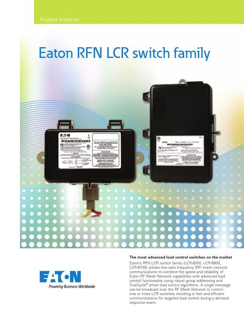
Eaton RFN LCR switch familyProduct brochureThe most advanced load control switches on the market Eaton’s RFN LCR switch family (LCR-6200, LCR-6600, LCR-6700) utilizes the radio frequency (RF) mesh network communications to combine the speed and reliability of Eaton RF Mesh Network capabilities with advanced load control functionality using robust group addressing andTrueCycle ® smart load control algorithms. A single message can be broadcast over the RF Mesh Network to control one or more LCR switches resulting in fast and efficient communications for targeted load control during a demand response event.Eaton’s LCR switches are the most advanced load control switches on the market—providing power quality protection for improved grid reliability and advancedload control functionality using robust group addressing and TrueCycle® smart load control algorithms to maximize demand reduction yield and automate measurement and verification data collection.Eaton’s RFN LCR switches have enhanced capabilities when combined with Eaton’s RF Mesh Network communications module. The RF Mesh Network communications module allows for a wide range of two-way data to be collected and broadcast commands to be disbursed to quickly initiate a control event. It also offers flexibility to build out a mesh network starting with the utility’s most critical devices.The LCR-6200RFN switch is designed specifically for quick and clean installon HVAC systems. The solution is also used to control strip heat.The single 5 amp relay is used to cycle the HVAC control circuit to reducethe AC demand while maintaining customer comfort.The LCR-6600RFNswitch is designedfor versatility.It can be delivered withmultiple 5 amp and 30 amprelays so that it can controlmultiple loads with a singleLCR switch. Each relay canbe addressed and controlledindividually, or they can beoperated simultaneously ifthe application requires.The LCR-6700RFNswitch is designedfor easy retrofitinto select legacyload managementswitches.It can be ordered withrelay configurations thatmatch the legacy switchit is replacing. It allowsthe investment in theinstall wiring to bemaintained, while makingthe hardware upgradequick and error-proof.2Installation andcontrol flexibility• The LCR switches were designed incollaboration with installation contractorsto minimize implementation costsand time• The LCR-6200 switch utilizes a small boxfootprint supporting a single 5A relay forHVAC only applications• The LCR-6700 and LCR-6600 switchesallow for up to 3 loads to be controlledfrom a single unit• The LCR-6700 switch control board iscapable of retrofitting into legacy 3rd partyenclosures for an easy upgrade path• LCR-6600 277/480VAC and 24VAC inputvoltages for custom applications. TheLCR-6600 277/480VAC is commonlyutilized for Irrigation Control applicationsOptimize participation• Optimized air conditioner cycling withsmart control and learning capabilities.Maximize demand reduction whilemaintaining customer comfortReliable network• RF Mesh Network can be installed as anindependent demand response systemwithout (or prior to) installation of anAMI metering system• Expands and strengthens existing RFmesh AMI infrastructure• Eaton RF Mesh Network offers broadcastcommunications for rapid, on-demand,system-wide control for demandresponse eventsImproved operations• Daily automated or on-demand datacollection provides vital appliance runtimeand event information for performingmeasurement and verification (M&V)studies• Automatic daily operability testing in theform of the daily Broadcast VerificationReport• Remote/local programmability• Over-the-air universal firmware upgradesupport• Power quality protection through supportof Cold Load Pickup and Voltage andFrequency ResponseYukon™ advanced demandresponse management• Utilizes the well-established Yukon™demand response and inventorymanagement modules• The reporting capabilities of Yukon allowa user to compile response data from aspecified group of switches into valuableinformation• Asset Availability Report and LoadEstimation Module provide insight intothe amount of load reduction a utilitycan expect from the system as they gothrough resource planningSmart cyclingEaton’s proprietary TrueCycle technologyallows smart air conditioner cycling controlfor homes with non-standard or oversizedair conditioning units maximizing yield whilemaintaining customer comfort.TrueCycle technology adjusts to the home’shourly runtime profile, balancing demandreduction and customer comfort on ahome-by-home, hour-by-hour basis.RF Mesh NetworkcommunicationsThe speed and reliability of Eaton’sRF Mesh Network allows for two-waycommunications and a large amount ofdata collection from every device.Each LCR switch acts as an independentdevice in the mesh network and can bedeployed with or without AMI meters. ALCR switch will pass network traffic throughand act as an additional path for other meshnetwork nodes to utilize and strengthenthe mesh. The broadcast capability of themesh network allows for rapid, on-demand,system-wide control for targeted loadcontrol events and emergency situations.Eaton’s RF Mesh Network solution is100% self-forming, self-managing, andself-healing, providing lower implementationand maintenance costs, resulting in alower total cost of ownership. Broadcastavailability report provides the utility withpeace of mind that the system will operatewhen it dispatches a demand responseevent. The report also helps utilitiesminimize their maintenance costs bytargeting LCR switches specifically inneed of maintenance. Advanced feature setThe RFN LCR switches with RF Mesh Network communications offers:3EATON RFN LCR switch family brochure30A at 240 VAC resistive, Form BPower quality protectionEaton’s RFN LCR switches can automatically shed the connected load if the supply frequency or voltage drops below configurable thresholds.Cold load pickup can be enabled or disabled for the connected load to minimize feeder in-rush following power outages.System and appliance protection The condition of the device is continually monitored. If an abnormality is detected, the microprocessor resets itself and the connected load is returned to its normal state.LED indicatorsIn the viewing window, green and yellow LEDs display diagnostics information. Red LEDs indicate the load is under control or a possible circuit fault. A blue LED indicator is also visible through the top of the LCR switch to show the RFN status. A solid light indicates an active connection to the RF Mesh Network.LocalcommunicationsA user can locally access a device to check the operating status, or troubleshoot using Eaton Network Scout™ application.Network Scout is a field tool designed to help the tech investigate the RFN mesh communication system.Remote addition or removal of customer participants Commands to enable or disable the device functions can be sent to individual devices. Deactivation can be sent with either a ‘temporary’ or ‘permanent’ setting. This feature improves customer service by reducing customer complaints and minimizing on-site service calls.Measurement and verificationThe data log of the RFN LCR switches can collect hourly appliance runtime and relayshed time. This information read automatically or on-demand over-the-air.Over-the-airconfiguration and firmware upgradesOver-the-air (OTA) programming or addressing, plus individual control or control override communication can update securely. Devices can be configured individually, in dedicated groups, or globally. OTA firmware upgrades are also supported for the RFN LCR switches.For more informations, visit/smartgridFollow us on social media to get thelatest product and support information.Eaton is a registered trademark. All other trademarks are property of their respective owners.Eaton1000 Eaton Boulevard Cleveland, OH 44122United States EatonElectrical Automation Solutions Division 3033 Campus Drive, Suite 350N Minneapolis, MN 55441United States/SmartGrid© 2018 EatonAll Rights Reserved Printed in USAPublication No. BR911001EN / GG April 2018。
伊顿E系列终端配电产品家族成员:E6X ED6X系列微型断路器和漏电断路器说明说明书

全球商业动力之源提供动力。
我们提供:探索今天的伊顿作为一家全球性多元化动力管理公司,我们帮助世界各地的客户管理用于建筑、飞机、卡车、汽车、机器和业务的动力。
伊顿的创新技术可帮助客户更为可靠、有效、安全和可持续地管理电力动力、液压动力和机械动力。
我们提供综合的解决方案,可让各种形式的能源更为实用,更易于获取。
2017年,伊顿的销售额达204亿美元,在全球拥有约9.6万名员工,产品销往超过175个国家和地区。
• 耗能更少,可改善动力可靠性,并让我们的生活和工作场所更加安全、舒适的电气解决方案• 既提高机器生产效率,又节约能源的液压和电气解决方案• 令飞机更轻、更安全、运营成本更低,和帮助机场更高效运营的航空解决方案• 为汽车、卡车和巴士提供更多动力,同时减少燃油消耗与排放的车辆动力传动及动力总成解决方案1E6X / ED6X 系列微型断路器和漏电断路器 /electricalE6X / ED6X 系列微型断路器和漏电断路器伊顿E系列终端配电产品家族全新成员伊顿在现有E6系列微型断路器的基础上,全新推出6kA 分断能力的新产品:E6X 系列微型断路器,以及ED6X 系列带过载保护的漏电断路器。
新系列广泛适用于民用建筑市场和OEM 客户,进一步深入细分市场,全方位满足客户的不同需求。
特性与优势• 具备状态指示窗口。
内部触点状态一目了然,大大提高了系统的安全性;• 独特的灭弧系统设计,确保将您的电气故障快速可靠地分断;• 与E6系列产品高度兼容,使客户可以不做大的设计变更而升级系统;• E6X 断路器都可作为进线端,而分断能力不受影响。
主要性能参数额定电压 (U e )额定电流脱扣特性分断能力额定冲击耐受电压 U imp 额定漏电流漏电保护类型进线方式极数宽度工作环境温度外壳防护等级电气寿命机械寿命端子形式端子接线能力推荐母排截面积额定端子扭矩符合标准认证证书240/415Vac @ 50/60Hz6 -63 AN/A N/A上下都可作为进线端18mm/极-25 ~ +75°C (6A :-25 ~ +60°C )IP20 (安装前);IP40 (安装后) 8000次通断 15000次通断导线连接或母排连接,不可同时连接母排及导线导线1 ~ 25mm²6 - 32A :10mm² ;40 - 63A :16mm² 2.5N·m GB10963.1 / IEC 60898-1 CCCB, C, D 6 kA 4kV 1P, 1P+N, 2P, 3P, 4P C, D 6 kA30mA, 300mA AC 型,瞬动型上进下出1P+N, 2P, 3P, 3P+N, 4P 见具体尺寸图GB16917.1 / GB16917.22E6X 系列MCBED6X 系列RCBO2E6X / ED6X 系列微型断路器和漏电断路器 /electrical 3P E6X2PED6X1P E6X过载 / 短路保护脱扣曲线3E6X / ED6X 系列微型断路器和漏电断路器/electrical电流温度补偿系数环境温度对热脱扣的影响根据环境温度调整额定电流值4E6X / ED6X 系列微型断路器和漏电断路器 /electrical 1P2P/1P+N4P3P 1P+N2P4P3P产品尺寸图(单位: mm )附件辅助触点E6X 外形尺寸图ED6X RCBO外形尺寸图辅助触点1NO+1NC230Vac 分励脱扣器24Vdc 分励脱扣器ZX-AHKZ-ASA/230Z-ASA/2490000025000847248287248286用于E6X/ED6X 连接图型号订货号附件5E6X / ED6X 系列微型断路器和漏电断路器 /electrical触点类型工作温度设计标准额定工作电压额定发热电流额定工作电流 I th 端子类型端子接线能力端子最大扭矩宽度1NO+1NC -25 ~ +75°CGB/T 20640-2006; IEC62019:2003U max = 230V AC U min = 5V DC 4AAC13 = 4A / 230V, DC13 = 0.5A / 110V 方形,可以支持单股硬线/多股绞合线1x 0.5 - 2.5 或 2 x 0.5 - 2 x 1.5mm 20.8Nm 9mm (0.5模数)ZX-AHK技术规格尺寸图ZX-AHKZ-ASA/230和Z-ASA/24最小脉宽内阻脱扣时间额定峰值耐受电压(1.2/50µs)操作寿命交流操作电压最大交流电流消耗直流操作电压最大直流电流消耗宽度10 ms 215Ω<20ms 2.5kV > 4000次110-415V 15A @ 10ms 110-220V 21A @ 2ms 17.5mm (1模数)15 ms 2.2Ω12-110V 10-60V Z-ASA/230Z-ASA/24E6X, 6kA, B曲线90000025000523 90000025000524 90000025000525 90000025000526 90000025000527 90000025000528 90000025000529 90000025000530 90000025000531 90000025000532 90000025000533 90000025000534 90000025000535 90000025000536 90000025000537 90000025000538 90000025000539 90000025000540 90000025000541 90000025000542 90000025000543 90000025000544 90000025000545 90000025000546 90000025000547 90000025000548 90000025000549E6X-6/1/BE6X-10/1/BE6X-16/1/BE6X-20/1/BE6X-25/1/BE6X-32/1/BE6X-40/1/BE6X-50/1/BE6X-63/1/BE6X-6/1N/BE6X-10/1N/BE6X-16/1N/BE6X-20/1N/BE6X-25/1N/BE6X-32/1N/BE6X-40/1N/BE6X-50/1N/BE6X-63/1N/BE6X-6/2/BE6X-10/2/BE6X-16/2/BE6X-20/2/BE6X-25/2/BE6X-32/2/BE6X-40/2/BE6X-50/2/BE6X-63/2/BE6X 6A 1P B 6kAE6X 10A 1P B 6kAE6X 16A 1P B 6kAE6X 20A 1P B 6kAE6X 25A 1P B 6kAE6X 32A 1P B 6kAE6X 40A 1P B 6kAE6X 50A 1P B 6kAE6X 63A 1P B 6kAE6X 6A 1P+N B 6kAE6X 10A 1P+N B 6kAE6X 16A 1P+N B 6kAE6X 20A 1P+N B 6kAE6X 25A 1P+N B 6kAE6X 32A 1P+N B 6kAE6X 40A 1P+N B 6kAE6X 50A 1P+N B 6kAE6X 63A 1P+N B 6kAE6X 6A 2P B 6kAE6X 10A 2P B 6kAE6X 16A 2P B 6kAE6X 20A 2P B 6kAE6X 25A 2P B 6kAE6X 32A 2P B 6kAE6X 40A 2P B 6kAE6X 50A 2P B 6kAE6X 63A 2P B 6kA900000250005509000002500055190000025000552900000250005539000002500055490000025000555900000250005569000002500055790000025000558900000250010249000002500102590000025001026900000250010279000002500102890000025001029900000250010309000002500103190000025001032E6X-6/3/BE6X-10/3/BE6X-16/3/BE6X-20/3/BE6X-25/3/BE6X-32/3/BE6X-40/3/BE6X-50/3/BE6X-63/3/BE6X-6/4/BE6X-10/4/BE6X-16/4/BE6X-20/4/BE6X-25/4/BE6X-32/4/BE6X-40/4/BE6X-50/4/BE6X-63/4/BE6X 6A 3P B 6kAE6X 10A 3P B 6kAE6X 16A 3P B 6kAE6X 20A 3P B 6kAE6X 25A 3P B 6kAE6X 32A 3P B 6kAE6X 40A 3P B 6kAE6X 50A 3P B 6kAE6X 63A 3P B 6kAE6X 6A 4P B 6kAE6X 10A 4P B 6kAE6X 16A 4P B 6kAE6X 20A 4P B 6kAE6X 25A 4P B 6kAE6X 32A 4P B 6kAE6X 40A 4P B 6kAE6X 50A 4P B 6kAE6X 63A 4P B 6kA 产品型号订货号产品描述E6X, 6kA, B曲线 (续)产品型号订货号产品描述6 E6X / ED6X 系列微型断路器和漏电断路器/electricalE6X, 6kA, D 曲线产品型号订货号产品描述E6X, 6kA, C 曲线产品型号订货号产品描述900000250005959000002500059690000025000597900000250005989000002500059990000025000600900000250006019000002500060290000025000603900000250006049000002500060590000025000606900000250006079000002500060890000025000609900000250006109000002500061190000025000612900000250006139000002500061490000025000615900000250006169000002500061790000025000618900000250006199000002500062090000025000621900000250006229000002500062390000025000624900000250006259000002500062690000025000627900000250006289000002500062990000025000630900000250010429000002500104390000025001044900000250010459000002500104690000025001047900000250010489000002500104990000025001050E6X-6/1/D E6X-10/1/D E6X-16/1/D E6X-20/1/D E6X-25/1/D E6X-32/1/D E6X-40/1/D E6X-50/1/D E6X-63/1/D E6X-6/1N/D E6X-10/1N/D E6X-16/1N/D E6X-20/1N/D E6X-25/1N/D E6X-32/1N/D E6X-40/1N/D E6X-50/1N/D E6X-63/1N/D E6X-6/2/D E6X-10/2/D E6X-16/2/D E6X-20/2/D E6X-25/2/D E6X-32/2/D E6X-40/2/D E6X-50/2/D E6X-63/2/D E6X-6/3/D E6X-10/3/D E6X-16/3/D E6X-20/3/D E6X-25/3/D E6X-32/3/D E6X-40/3/D E6X-50/3/D E6X-63/3/D E6X-6/4/D E6X-10/4/D E6X-16/4/D E6X-20/4/D E6X-25/4/D E6X-32/4/D E6X-40/4/D E6X-50/4/D E6X-63/4/D E6X 6A 1P D 6kA E6X 10A 1P D 6kA E6X 16A 1P D 6kA E6X 20A 1P D 6kA E6X 25A 1P D 6kA E6X 32A 1P D 6kA E6X 40A 1P D 6kA E6X 50A 1P D 6kA E6X 63A 1P D 6kA E6X 6A 1P+N D 6kA E6X 10A 1P+N D 6kA E6X 16A 1P+N D 6kA E6X 20A 1P+N D 6kA E6X 25A 1P+N D 6kA E6X 32A 1P+N D 6kA E6X 40A 1P+N D 6kA E6X 50A 1P+N D 6kA E6X 63A 1P+N D 6kA E6X 6A 2P D 6kA E6X 10A 2P D 6kA E6X 16A 2P D 6kA E6X 20A 2P D 6kA E6X 25A 2P D 6kA E6X 32A 2P D 6kA E6X 40A 2P D 6kA E6X 50A 2P D 6kA E6X 63A 2P D 6kA E6X 6A 3P D 6kA E6X 10A 3P D 6kA E6X 16A 3P D 6kA E6X 20A 3P D 6kA E6X 25A 3P D 6kA E6X 32A 3P D 6kA E6X 40A 3P D 6kA E6X 50A 3P D 6kA E6X 63A 3P D 6kA E6X 6A 4P D 6kA E6X 10A 4P D 6kA E6X 16A 4P D 6kA E6X 20A 4P D 6kA E6X 25A 4P D 6kA E6X 32A 4P D 6kA E6X 40A 4P D 6kA E6X 50A 4P D 6kA E6X 63A 4P D 6kA900000250005599000002500056090000025000561900000250005629000002500056390000025000564900000250005659000002500056690000025000567900000250005689000002500056990000025000570900000250005719000002500057290000025000573900000250005749000002500057590000025000576900000250005779000002500057890000025000579900000250005809000002500058190000025000582900000250005839000002500058490000025000585900000250005869000002500058790000025000588900000250005899000002500059090000025000591900000250005929000002500059390000025000594900000250010339000002500103490000025001035900000250010369000002500103790000025001038900000250010399000002500104090000025001041E6X-6/1/C E6X-10/1/C E6X-16/1/C E6X-20/1/C E6X-25/1/C E6X-32/1/C E6X-40/1/C E6X-50/1/C E6X-63/1/C E6X-6/1N/C E6X-10/1N/C E6X-16/1N/C E6X-20/1N/C E6X-25/1N/C E6X-32/1N/C E6X-40/1N/C E6X-50/1N/C E6X-63/1N/C E6X-6/2/C E6X-10/2/C E6X-16/2/C E6X-20/2/C E6X-25/2/C E6X-32/2/C E6X-40/2/C E6X-50/2/C E6X-63/2/C E6X-6/3/C E6X-10/3/C E6X-16/3/C E6X-20/3/C E6X-25/3/C E6X-32/3/C E6X-40/3/C E6X-50/3/C E6X-63/3/C E6X-6/4/C E6X-10/4/C E6X-16/4/C E6X-20/4/C E6X-25/4/C E6X-32/4/C E6X-40/4/C E6X-50/4/C E6X-63/4/C E6X 6A 1P C 6kA E6X 10A 1P C 6kA E6X 16A 1P C 6kA E6X 20A 1P C 6kA E6X 25A 1P C 6kA E6X 32A 1P C 6kA E6X 40A 1P C 6kA E6X 50A 1P C 6kA E6X 63A 1P C 6kA E6X 6A 1P+N C 6kA E6X 10A 1P+N C 6kA E6X 16A 1P+N C 6kA E6X 20A 1P+N C 6kA E6X 25A 1P+N C 6kA E6X 32A 1P+N C 6kA E6X 40A 1P+N C 6kA E6X 50A 1P+N C 6kA E6X 63A 1P+N C 6kA E6X 6A 2P C 6kA E6X 10A 2P C 6kA E6X 16A 2P C 6kA E6X 20A 2P C 6kA E6X 25A 2P C 6kA E6X 32A 2P C 6kA E6X 40A 2P C 6kA E6X 50A 2P C 6kA E6X 63A 2P C 6kA E6X 6A 3P C 6kA E6X 10A 3P C 6kA E6X 16A 3P C 6kA E6X 20A 3P C 6kA E6X 25A 3P C 6kA E6X 32A 3P C 6kA E6X 40A 3P C 6kA E6X 50A 3P C 6kA E6X 63A 3P C 6kA E6X 6A 4P C 6kA E6X 10A 4P C 6kA E6X 16A 4P C 6kA E6X 20A 4P C 6kA E6X 25A 4P C 6kA E6X 32A 4P C 6kA E6X 40A 4P C 6kA E6X 50A 4P C 6kA E6X 63A 4P C 6kA 7E6X / ED6X 系列微型断路器和漏电断路器 /electrical1极+N90000025000958 90000025000959 90000025000960 90000025000961 90000025000962 90000025000963 90000025000964 90000025000965 90000025000966 90000025000967 90000025000968 90000025000969 90000025000970 90000025000971 90000025000972 90000025000973 90000025000974 90000025000975 2极90000025000850 90000025000851 90000025000852 90000025000853 90000025000854 90000025000855 90000025000856 90000025000857 90000025000858 90000025000877 90000025000878 90000025000879 90000025000880 90000025000881 90000025000882 90000025000883 90000025000884 90000025000885ED6X-6/1N/C/003ED6X-10/1N/C/003ED6X-16/1N/C/003ED6X-20/1N/C/003ED6X-25/1N/C/003ED6X-32/1N/C/003ED6X-40/1N/C/003ED6X-50/1N/C/003ED6X-63/1N/C/003ED6X-6/1N/C/03ED6X-10/1N/C/03ED6X-16/1N/C/03ED6X-20/1N/C/03ED6X-25/1N/C/03ED6X-32/1N/C/03ED6X-40/1N/C/03ED6X-50/1N/C/03ED6X-63/1N/C/03ED6X-6/2/C/003ED6X-10/2/C/003ED6X-16/2/C/003ED6X-20/2/C/003ED6X-25/2/C/003ED6X-32/2/C/003ED6X-40/2/C/003ED6X-50/2/C/003ED6X-63/2/C/003ED6X-6/2/C/03ED6X-10/2/C/03ED6X-16/2/C/03ED6X-20/2/C/03ED6X-25/2/C/03ED6X-32/2/C/03ED6X-40/2/C/03ED6X-50/2/C/03ED6X-63/2/C/03ED6X, 6A, C, 1P+N, 30mA, AC瞬动型ED6X, 10A, C, 1P+N, 30mA, AC瞬动型ED6X, 16A, C, 1P+N, 30mA, AC瞬动型ED6X, 20A, C, 1P+N, 30mA, AC瞬动型ED6X, 25A, C, 1P+N, 30mA, AC瞬动型ED6X, 32A, C, 1P+N, 30mA, AC瞬动型ED6X, 40A, C, 1P+N, 30mA, AC瞬动型ED6X, 50A, C, 1P+N, 30mA, AC瞬动型ED6X, 63A, C, 1P+N, 30mA, AC瞬动型ED6X, 6A, C, 1P+N, 300mA, AC瞬动型ED6X, 10A, C, 1P+N, 300mA, AC瞬动型ED6X, 16A, C, 1P+N, 300mA, AC瞬动型ED6X, 20A, C, 1P+N, 300mA, AC瞬动型ED6X, 25A, C, 1P+N, 300mA, AC瞬动型ED6X, 32A, C, 1P+N, 300mA, AC瞬动型ED6X, 40A, C, 1P+N, 300mA, AC瞬动型ED6X, 50A, C, 1P+N, 300mA, AC瞬动型ED6X, 63A, C, 1P+N, 300mA, AC瞬动型ED6X, 6A, C, 2P, 30mA, AC瞬动型ED6X, 10A, C, 2P, 30mA, AC瞬动型ED6X, 16A, C, 2P, 30mA, AC瞬动型ED6X, 20A, C, 2P, 30mA, AC瞬动型ED6X, 25A, C, 2P, 30mA, AC瞬动型ED6X, 32A, C, 2P, 30mA, AC瞬动型ED6X, 40A, C, 2P, 30mA, AC瞬动型ED6X, 50A, C, 2P, 30mA, AC瞬动型ED6X, 63A, C, 2P, 30mA, AC瞬动型ED6X, 6A, C, 2P, 300mA, AC瞬动型ED6X, 10A, C, 2P, 300mA, AC瞬动型ED6X, 16A, C, 2P, 300mA, AC瞬动型ED6X, 20A, C, 2P, 300mA, AC瞬动型ED6X, 25A, C, 2P, 300mA, AC瞬动型ED6X, 32A, C, 2P, 300mA, AC瞬动型ED6X, 40A, C, 2P, 300mA, AC瞬动型ED6X, 50A, C, 2P, 300mA, AC瞬动型ED6X, 63A, C, 2P, 300mA, AC瞬动型产品型号订货号产品描述ED6X漏电断路器,C曲线ED6X漏电断路器,C曲线 (续)产品型号订货号产品描述3极90000025000859 90000025000860 90000025000861 90000025000862 90000025000863 90000025000864 90000025000865 90000025000866 90000025000867 90000025000886 90000025000887 90000025000888 90000025000889 90000025000890 90000025000891 90000025000892 90000025000893 90000025000894 4极90000025000868 90000025000869 90000025000870 90000025000871 90000025000872 90000025000873 90000025000874 90000025000875 90000025000876 90000025000895 90000025000896 90000025000897 90000025000898 90000025000899 90000025000900 90000025000901 90000025000902 90000025000903ED6X-6/3/C/003ED6X-10/3/C/003ED6X-16/3/C/003ED6X-20/3/C/003ED6X-25/3/C/003ED6X-32/3/C/003ED6X-40/3/C/003ED6X-50/3/C/003ED6X-63/3/C/003ED6X-6/3/C/03ED6X-10/3/C/03ED6X-16/3/C/03ED6X-20/3/C/03ED6X-25/3/C/03ED6X-32/3/C/03ED6X-40/3/C/03ED6X-50/3/C/03ED6X-63/3/C/03ED6X-6/4/C/003ED6X-10/4/C/003ED6X-16/4/C/003ED6X-20/4/C/003ED6X-25/4/C/003ED6X-32/4/C/003ED6X-40/4/C/003ED6X-50/4/C/003ED6X-63/4/C/003ED6X-6/4/C/03ED6X-10/4/C/03ED6X-16/4/C/03ED6X-20/4/C/03ED6X-25/4/C/03ED6X-32/4/C/03ED6X-40/4/C/03ED6X-50/4/C/03ED6X-63/4/C/03ED6X, 6A, C, 3P, 30mA, AC瞬动型ED6X, 10A, C, 3P, 30mA, AC瞬动型ED6X, 16A, C, 3P, 30mA, AC瞬动型ED6X, 20A, C, 3P, 30mA, AC瞬动型ED6X, 25A, C, 3P, 30mA, AC瞬动型ED6X, 32A, C, 3P, 30mA, AC瞬动型ED6X, 40A, C, 3P, 30mA, AC瞬动型ED6X, 50A, C, 3P, 30mA, AC瞬动型ED6X, 63A, C, 3P, 30mA, AC瞬动型ED6X, 6A, C, 3P, 300mA, AC瞬动型ED6X, 10A, C, 3P, 300mA, AC瞬动型ED6X, 16A, C, 3P, 300mA, AC瞬动型ED6X, 20A, C, 3P, 300mA, AC瞬动型ED6X, 25A, C, 3P, 300mA, AC瞬动型ED6X, 32A, C, 3P, 300mA, AC瞬动型ED6X, 40A, C, 3P, 300mA, AC瞬动型ED6X, 50A, C, 3P, 300mA, AC瞬动型ED6X, 63A, C, 3P, 300mA, AC瞬动型ED6X, 6A, C, 4P, 30mA, AC瞬动型ED6X, 10A, C, 4P, 30mA, AC瞬动型ED6X, 16A, C, 4P, 30mA, AC瞬动型ED6X, 20A, C, 4P, 30mA, AC瞬动型ED6X, 25A, C, 4P, 30mA, AC瞬动型ED6X, 32A, C, 4P, 30mA, AC瞬动型ED6X, 40A, C, 4P, 30mA, AC瞬动型ED6X, 50A, C, 4P, 30mA, AC瞬动型ED6X, 63A, C, 4P, 30mA, AC瞬动型ED6X, 6A, C, 4P, 300mA, AC瞬动型ED6X, 10A, C, 4P, 300mA, AC瞬动型ED6X, 16A, C, 4P, 300mA, AC瞬动型ED6X, 20A, C, 4P, 300mA, AC瞬动型ED6X, 25A, C, 4P, 300mA, AC瞬动型ED6X, 32A, C, 4P, 300mA, AC瞬动型ED6X, 40A, C, 4P, 300mA, AC瞬动型ED6X, 50A, C, 4P, 300mA, AC瞬动型ED6X, 63A, C, 4P, 300mA, AC瞬动型8E6X / ED6X 系列微型断路器和漏电断路器/electrical订购指南产品型号订货号产品描述ED6X 漏电断路器,D 曲线ED6X 漏电断路器,D 曲线 (续)产品型号订货号产品描述3极9000002500091390000025000914900000250009159000002500091690000025000917900000250009189000002500091990000025000920900000250009219000002500094090000025000941900000250009429000002500094390000025000944900000250009459000002500094690000025000947900000250009484极900000250009229000002500092390000025000924900000250009259000002500092690000025000927900000250009289000002500092990000025000930900000250009499000002500095090000025000951900000250009529000002500095390000025000954900000250009559000002500095690000025000957ED6X-6/3/D/003ED6X-10/3/D/003ED6X-16/3/D/003ED6X-20/3/D/003ED6X-25/3/D/003ED6X-32/3/D/003ED6X-40/3/D/003ED6X-50/3/D/003ED6X-63/3/D/003ED6X-6/3/D/03ED6X-10/3/D/03ED6X-16/3/D/03ED6X-20/3/D/03ED6X-25/3/D/03ED6X-32/3/D/03ED6X-40/3/D/03ED6X-50/3/D/03ED6X-63/3/D/03ED6X-6/4/D/003ED6X-10/4/D/003ED6X-16/4/D/003ED6X-20/4/D/003ED6X-25/4/D/003ED6X-32/4/D/003ED6X-40/4/D/003ED6X-50/4/D/003ED6X-63/4/D/003ED6X-6/4/D/03ED6X-10/4/D/03ED6X-16/4/D/03ED6X-20/4/D/03ED6X-25/4/D/03ED6X-32/4/D/03ED6X-40/4/D/03ED6X-50/4/D/03ED6X-63/4/D/03ED6X, 6A, D, 3P, 30mA, AC 瞬动型ED6X, 10A, D, 3P, 30mA, AC 瞬动型ED6X, 16A, D, 3P, 30mA, AC 瞬动型ED6X, 20A, D, 3P, 30mA, AC 瞬动型ED6X, 25A, D, 3P, 30mA, AC 瞬动型ED6X, 32A, D, 3P, 30mA, AC 瞬动型ED6X, 40A, D, 3P, 30mA, AC 瞬动型ED6X, 50A, D, 3P, 30mA, AC 瞬动型ED6X, 63A, D, 3P, 30mA, AC 瞬动型ED6X, 6A, D, 3P, 300mA, AC 瞬动型ED6X, 10A, D, 3P, 300mA, AC 瞬动型ED6X, 16A, D, 3P, 300mA, AC 瞬动型ED6X, 20A, D, 3P, 300mA, AC 瞬动型ED6X, 25A, D, 3P, 300mA, AC 瞬动型ED6X, 32A, D, 3P, 300mA, AC 瞬动型ED6X, 40A, D, 3P, 300mA, AC 瞬动型ED6X, 50A, D, 3P, 300mA, AC 瞬动型ED6X, 63A, D, 3P, 300mA, AC 瞬动型ED6X, 6A, D, 4P, 30mA, AC 瞬动型ED6X, 10A, D, 4P, 30mA, AC 瞬动型ED6X, 16A, D, 4P, 30mA, AC 瞬动型ED6X, 20A, D, 4P, 30mA, AC 瞬动型ED6X, 25A, D, 4P, 30mA, AC 瞬动型ED6X, 32A, D, 4P, 30mA, AC 瞬动型ED6X, 40A, D, 4P, 30mA, AC 瞬动型ED6X, 50A, D, 4P, 30mA, AC 瞬动型ED6X, 63A, D, 4P, 30mA, AC 瞬动型ED6X, 6A, D, 4P, 300mA, AC 瞬动型ED6X, 10A, D, 4P, 300mA, AC 瞬动型ED6X, 16A, D, 4P, 300mA, AC 瞬动型ED6X, 20A, D, 4P, 300mA, AC 瞬动型ED6X, 25A, D, 4P, 300mA, AC 瞬动型ED6X, 32A, D, 4P, 300mA, AC 瞬动型ED6X, 40A, D, 4P, 300mA, AC 瞬动型ED6X, 50A, D, 4P, 300mA, AC 瞬动型ED6X, 63A, D, 4P, 300mA, AC 瞬动型1极+N 9000002500097690000025000977900000250009789000002500097990000025000980900000250009819000002500098290000025000983900000250009849000002500098590000025000986900000250009879000002500098890000025000989900000250009909000002500099190000025000992900000250009932极900000250009049000002500090590000025000906900000250009079000002500090890000025000909900000250009109000002500091190000025000912900000250009319000002500093290000025000933900000250009349000002500093590000025000936900000250009379000002500093890000025000939ED6X-6/1N/D/003ED6X-10/1N/D/003ED6X-16/1N/D/003ED6X-20/1N/D/003ED6X-25/1N/D/003ED6X-32/1N/D/003ED6X-40/1N/D/003ED6X-50/1N/D/003ED6X-63/1N/D/003ED6X-6/1N/D/03ED6X-10/1N/D/03ED6X-16/1N/D/03ED6X-20/1N/D/03ED6X-25/1N/D/03ED6X-32/1N/D/03ED6X-40/1N/D/03ED6X-50/1N/D/03ED6X-63/1N/D/03ED6X-6/2/D/003ED6X-10/2/D/003ED6X-16/2/D/003ED6X-20/2/D/003ED6X-25/2/D/003ED6X-32/2/D/003ED6X-40/2/D/003ED6X-50/2/D/003ED6X-63/2/D/003ED6X-6/2/D/03ED6X-10/2/D/03ED6X-16/2/D/03ED6X-20/2/D/03ED6X-25/2/D/03ED6X-32/2/D/03ED6X-40/2/D/03ED6X-50/2/D/03ED6X-63/2/D/03ED6X, 6A, D, 1P+N, 30mA, AC 瞬动型ED6X, 10A, D, 1P+N, 30mA, AC 瞬动型ED6X, 16A, D, 1P+N, 30mA, AC 瞬动型ED6X, 20A, D, 1P+N, 30mA, AC 瞬动型ED6X, 25A, D, 1P+N, 30mA, AC 瞬动型ED6X, 32A, D, 1P+N, 30mA, AC 瞬动型ED6X, 40A, D, 1P+N, 30mA, AC 瞬动型ED6X, 50A, D, 1P+N, 30mA, AC 瞬动型ED6X, 63A, D, 1P+N, 30mA, AC 瞬动型ED6X, 6A, D, 1P+N, 300mA, AC 瞬动型ED6X, 10A, D, 1P+N, 300mA, AC 瞬动型ED6X, 16A, D, 1P+N, 300mA, AC 瞬动型ED6X, 20A, D, 1P+N, 300mA, AC 瞬动型ED6X, 25A, D, 1P+N, 300mA, AC 瞬动型ED6X, 32A, D, 1P+N, 300mA, AC 瞬动型ED6X, 40A, D, 1P+N, 300mA, AC 瞬动型ED6X, 50A, D, 1P+N, 300mA, AC 瞬动型ED6X, 63A, D, 1P+N, 300mA, AC 瞬动型ED6X, 6A, D, 2P, 30mA, AC 瞬动型ED6X, 10A, D, 2P, 30mA, AC 瞬动型ED6X, 16A, D, 2P, 30mA, AC 瞬动型ED6X, 20A, D, 2P, 30mA, AC 瞬动型ED6X, 25A, D, 2P, 30mA, AC 瞬动型ED6X, 32A, D, 2P, 30mA, AC 瞬动型ED6X, 40A, D, 2P, 30mA, AC 瞬动型ED6X, 50A, D, 2P, 30mA, AC 瞬动型ED6X, 63A, D, 2P, 30mA, AC 瞬动型ED6X, 6A, D, 2P, 300mA, AC 瞬动型ED6X, 10A, D, 2P, 300mA, AC 瞬动型ED6X, 16A, D, 2P, 300mA, AC 瞬动型ED6X, 20A, D, 2P, 300mA, AC 瞬动型ED6X, 25A, D, 2P, 300mA, AC 瞬动型ED6X, 32A, D, 2P, 300mA, AC 瞬动型ED6X, 40A, D, 2P, 300mA, AC 瞬动型ED6X, 50A, D, 2P, 300mA, AC 瞬动型ED6X, 63A, D, 2P, 300mA, AC 瞬动型9E6X / ED6X 系列微型断路器和漏电断路器 /electrical伊顿公司亚太总部上海市长宁区临虹路280弄3号邮编: 200335© 2018 伊顿公司本公司保留对样本资料的解释权和修改权,并毋需另行通知。
电力设备:E-VAC EP系列中高压真空电路断路器说明书

E-VAC EP Series Medium Voltage Vacuum Circuit BreakerAutomotiveAerospaceTruckHydraulicsAutomotive Aerospace Truck Hydraulics Poweringbusiness worldwideEaton delivers the power inside hundreds of products that are answering the demands of today’s fast changing world. We help our customers worldwide manage the power they need for buildings, aircraft, trucks, cars, machinery and entire businesses. And we do it in a way that consumes fewer resources.Next generationtransportationEaton is driving the development of newtechnologies – from hybriddrivetrains and emission control systems to advanced engine components – that reduce fuel consumption and emissions in trucks and cars. Higher expectationsWe continue to expand our aerospace solutions andservices to meet the needs of new aviation platforms,including the high-flying light jet and very light jet markets. Building on our strengths Our hydraulics businesscombines localised service and support with an innovative portfolio of fluid powersolutions to answer the needs of global infrastructure projects, including locks, canals and dams.Powering Greener Buildings and BusinessesEaton’s Electrical Group is a leading provider of powerquality, distribution and control solutions that increase energy efficiency and improve power quality, safety and reliability. Our solutions offer a growing portfolio of “green” products and services, such as energy audits and real-time energy consumption monitoring.Eaton’s Uninterruptible Power Supplies (UPS), variable-speed drives and lighting controls help conserve energy and increase efficiency.ElectricalElectrical E-VAC EP Series Medium Voltage Vacuum Circuit Breaker 1Eaton Corporation is a worldwide leader in thedesign, manufacture, and sale of safe, reliableand high-performance medium voltage power distribution equipment in accordance with IEC,GB and ANSI standards.Complete Global Medium Voltage Switchgear Solutions Eaton, a premier leader in designing and manufacturing power distribution and protection equipment in the electrical industry, offers a comprehensive range of medium voltage (MV) solutionsto meet the needs of virtually every application. From productsthat feature cutting-edge design that allow for easy access, maintenance and space savings, to arc-resistant products that enhance safety, Eaton’s medium voltage solutions provide avariety of products for every need. Additionally, Eaton’s global service network provides maximum customer support in allregions of the world.As one of the few completely vertically integrated and diversified industrial manufacturers in the world, Eaton designs not only MV assemblies, but also the key components that comprise the MV solutions – from steel housing and circuit breaker compartmentsto vacuum interrupters, circuit breakers, bus systems and fuses. Eaton’s MV heritage, strengthened by acquisitions such as Westinghouse DCBU, Cutler Hammer, MEM and Holec, has resulted in breakthrough MV technologies and numerous international patents over the years.Part of Eaton’s complete electrical PowerChain Solutions– which help businesses minimize risks while realizing greater reliability, cost efficiencies, capital utilization and safety –Eaton’s medium voltage equipment meets all applicablestandards and certifications such as IEC, NEMA / ANSI, GB,UL, IEEE, KEMA and CSA.When it comes to medium voltage solutions, you can trust theone name with a long history of proven performance: Eaton.E-VAC EP Series Medium Voltage VacuE-VAC EP Series Medium Voltage Vacuum Circuit BreakerE-VAC EP Series medium voltage Ideal contact material and E-VAC EP Vacuum Circuit Breakervacuum circuit breakers from geometry ensure low Eaton Electrical combine our chopping current andexcellent vacuum technology reliable contact resistance . with decades of experience in designing and manufacturing A few components and power distribution system. They compact and reasonable offer high reliability, ease of structure ensure morehandling and maintenance, high reliable and safer operation. cost efficiency for Chinese users. Enable ideal cutoff and close Meet GB and DL standards. of resistance, inductance load and capacitive load. E-VAC equipped with new generation vacuum Secondary plug, chassis,interrupter, suited formoving contact and grounding technologies and operation methods are speciallycondition of power system. designed to Chinese users, completely compatible with E-VAC utilizes solid-enveloped domestically dominantpole of Eaton Electrical, offers medium voltage switchgear superior and reliable solid KYN28.enveloping insulation performance, passescondensation test, suitable for safely operating in harsh environment. It offers better creepage distance and clearance compared to the requirements in GB standards.Product modelsE -VAC -12 / T □ -□GB StandardEaton breaker seriesVoltage ratings kVRated current ARated short circuit breakingcurrent kASpring operation mechanismE-VAC EP Series Medium Voltage Vacuum Circuit Breaker3Application condition Technical features Temperature condition Ambient air temperature not E-VAC utilizes mature spring Product assembly utilizes The average of relative exceeding 40℃, and the operating mechanism, offers tooling method to ensure humidity measured within 24 average value measured within reliable and stable dimension consistency. All hours not exceeding 95%.24 hours not exceeding 35℃. performance, long service life, products have been subject toThe minimum ambient air ease of operating, excellent the push panel test for The average vapor pressure temperature is -15℃.corrosion protection and low standard panel, ensuring measured within 24 hours notmaintenance within the lifetime product interchangeability and exceeding 2.2kPa.The effect by solar radiation universality.can be ignored. E-VAC EP series 12kV vacuum The average of relativecircuit breaker adopts mature All products have been subject humidity measured within one The ambient air is not obviously APG process to enclose to hundreds of mechanical month not exceeding 90%.polluted by dust, smoke, vacuum interrupter and main operation running-in testscorrosive or flammable gases, conductive circuit in a before leaving the factory, The average vapor pressure vapor or salt mist. insulation tube, thoroughly ensuring the product measured within one montheliminating the environmental performance in the most stable not exceeding 1.8kPa.Seismic intensity not impact on insulated parts phase.exceeding 8 degree. which weakens the voltagewithstanding capacity, ensuring Utilize advanced importedAmplitude of electromagnetic the vacuum interrupter suitable testing equipment, exactlyinterference induced in for harsh environment. record no-load mechanicalsecondary system not characteristics of each product,exceeding 1.6kV. E2 level electrical life extended and provide users with theseand M2 level mechanical life characteristic curves, ensureextended as per GB1984-2003, product reliability.capacitive current breaking andlowre-breakdown probability C2level, having completed thetype test.Outline dimension anddistribution panel interlockingmethod completely compatiblewith domestically dominantmedium voltage switchgearKYN28, high universality,significantly reduce design cost4E-VAC EP Series Medium Voltage Vacuum Circuit BreakerE-VAC EP Series Medium Voltage Vacuum Circuit BreakerApplication areasChemical industry Substation Oil industry Cement industry Piping industry Automotive industry Offshore mining Power plantShipbuildingTextile and food industries Paper making industry Metallurgical industryOpencast coal mineT echnology creation historyAs the manufacturer of the world’s first vacuum interrupter, the pioneer of vacuum technology, Eaton Electrical has been committed to the research, development andmanufacturing of vacuum interrupters for over 70 years, and gathered plenty of experience. Westinghouse has become the synonym of quality and reliability.We own the world’s largest and globally leading vacuum interrupter plant and the only vacuum interrupter plant that is equipped with large capacity high voltage laboratories.Our manufacturing capacity and design and development always maintain a leadership position.E-VAC vacuum circuit breaker requires almost no relevant maintenanceSimple structure design of E-VAC vacuum circuit breaker further minimizes fault occurrence, simplifies daily maintenance. With the indicator on the circuit breaker panel, no detection instrument isrequired, facilitating the judgment of working state of circuit breaker. The circuit breaker utilizes the world’s first class Eaton Electrical’s vacuum interrupter with vacuum degree up to 10-6Pa, low air leakage, and ensure 50-year life with no maintenance required.Optional accessoriesCharging handle Trolley handle LifterIdeal for control and protection in medium voltage power supply and distribution systemThe circuit breaker is equipped with superior spring chargingmechanism, utilizes modular design, offering optimized mechanism main part distribution, simpler structure and more reliable performance. The whole mechanism is composed by three modules: charging,closing, opening. Assembly and maintenance of these three parts are very simple. The spring charging mechanism composed by ratchet wheel mechanism, oscillator and closing spring is compact and smart. The operating mechanism is usually equipped with manual charging device and electric charging device, enabling automatic reclosing function.The circuit for manual charging operating mechanism is provided with manual opening and closing operation buttons, circuit breaker position indicator and spring mechanism charging status indicator, switch operations counter, shunt release auxiliary switch, position and fault signals, etc..The circuit breaker of electric charging operating mechanism: added with spring charging motor, shunt release, trip free relay, and auxiliary switch for spring charging motor release.The following accessories can also be provided as needed: undervoltage release, overcurrent relay, etc..E-VAC EP Series Medium Voltage Vacuum Circuit Breaker5E-VAC EP Series Medium Voltage Vacuum Circuit BreakerMain specification and technical parametersItem Unit ValueRated voltage kV 12Rated short-time power frequency withstand voltage (1 min) 42 (phase to ground, phase to phase) 48 (gap)Rated lightning impulse withstand voltage (peak) 75 (phase to ground, phase to phase) 85 (gap)Rated frequency Hz 50Rated current A 630 630 1250 1250 1600 1250 16001250 1600 2000 2000 2500 2000 250040002500 2500 3150 3150 (1)4000 3150 (1) Rated short-circuit breaking current kA 25 31.5 40 50Rated short-time withstand current (4s) 25 31.5 40 50125Rated peak withstand current kA 63 80 100 (2)125Rated short circuit making current 63 80 100 (2) Secondary circuit power frequency withstand voltage (1 min) V 2000Opening time ms 20~50Closing time 35~70Mechanical endurance time 30000 (1600A/31.5kA and below), 20000 (2000A and above, 40kA), 10000(50kA) Rated current breaking endurance 30000 (1600A/31.5kA and below), 20000 (2000A and above, 40kA), 10000(50kA) Rated short circuit current breaking endurance time 50 (1600A/31.5kA and below), 30 (2000A and above, 40~50kA)Allowable accumulated wearingthickness of moving/fixed contact mm 3Rated closing operating voltage V AC 110/220 DC 110/220Rated opening operating voltageRated voltage of spring charging motor V AC 110/220 DC 110/220Rated power of spring charging motor W 55~90Charging duration s ≤15Rated operating sequence O-0.3s-CO-180s-CO (40kA and below), O-180s-CO-180s-CO (50kA)Note:(1) Forced air cooling is required at 4000A; (2) For higher parameters, please contact the Eaton Corp.T echnical parameters for trip/close coilsName ParameterRated operating voltage (V) AC, DC110 AC, DC220Rated operating current of close coil (A) 2.0 1.0Rated operating current of trip coil (A) 1.8 (40kA and above is 2.6) 0.9 (40kA and above is 1.6)Normal operating voltage range Closing: 80%~110% of rated operating voltageOpening: 65%~120% of rated operating voltage, opening will not occur when thenormal operating voltage is less than 30% of rated operating voltageE-VAC EP Series Medium Voltage Vacuum Circuit Breaker 6E-VAC EP Series Medium Voltage Vacuum Circuit BreakerOutline and dimension of E-VAC EP circuit breaker (drawout type)Distribution Rated Rated short panelcurrent circuit breaking width (mm) (A) current (kA)P H A B C D E G J K L M N R S T W Q 800 630 25~31.5 210 275 638 652 640 650 433 Φ35 280 598 76 78 637 508 277 40 23 / 800 1250 25~40 210 275 638 652 640 650 433 Φ49 280 598 76 78 637 508 277 40 23 550* 800 1600 31.5 210 275 638 652 640 650 433 Φ55 280 598 76 78 637 508 277 40 23 / 800 2000 40 210 310 638 652 640 650 361 Φ79 295 586 77 88 698 536 277 0 23 550 800 1250~2000 50 210 310 638 652 640 650 361Φ79295 586 77 88 698 536 277 0 19 550 1000 2500 31.5 275 310 838 852 838 850 361 Φ109 295 586 77 88 698 536 377 0 31 / 1000 3150 31.5 275 310 838 852 838 850 361 Φ109 295 586 77 88 725 536 377 0 31 / 10002500~400040~50275310 838 852838 850361 Φ109295586 77 88 725 53637731750**Note:Forced air cooling is required at 4000A. * 40kA only. ** 50kA only.E-VAC EP Series Medium Voltage Vacuum Circuit Breaker7E-VAC EP Series Medium Voltage Vacuum Circuit BreakerOutline and dimension of E-VAC EP circuit breaker (fixed type)E-VAC fixed type vacuum circuit breaker (210 phase space)Rated Rated shortcurrent circuit breaking(A) current (kA) H J E K B N Y1\Y2630~125025~31.527523771.54370555I 12504027523771.54370551II160031.5~4027523771.54370551II 200040310252804493614III1250~200050310252804493614IIIE-VAC EP Series Medium Voltage Vacuum Circuit Breaker 8E-VAC EP Series Medium Voltage Vacuum Circuit BreakerOutline and dimension of E-VAC EP circuit breaker (fixed type)E-VAC fixed type vacuum circuit breaker (275 phase space)Rated Rated short current circuit breaking (A) current (kA)M Z1\Z2 2500 31.5 628 IV 3150 31.5 678 V 2500~400040~50678VE-VAC EP Series Medium Voltage Vacuum Circuit Breaker9E-VAC EP Series Medium Voltage Vacuum Circuit BreakerSecondary control connection diagram of E-VAC EP series vacuum circuit breaker (drawout type) The diagram shows the circuit breaker in test position, opening, discharged statesE-VAC EP Series Medium Voltage Vacuum Circuit Breaker 10E-VAC EP Series Medium Voltage Vacuum Circuit BreakerSecondary control connection diagram of E-VAC EP series vacuum circuit breaker (fixed type) The diagram shows the circuit breaker in opening, discharged states11E-VAC EP Series Medium Voltage Vacuum Circuit BreakerE-VAC EP Series Medium Voltage Vacuum Circuit BreakerE-VAC EP series vacuum circuit breaker selection table1. Circuit breaker models□E-VAC (drawout type)□ E-VAC (fixe d type)2. Parameters of E-VAC EP series vacuum circuit breaker Panel width (mm) Breaker phase Rated short circuit Rated working current (A)spacing(mm) breaking current (kA) □630 □1250 80021025 □630□1250□ 160031.5 □1250 □ 1600 □ 2000 40 □1250 □ 1600□ 2000 501000 275 25 □2500 31.5 □2000□ 2500□ 315040 □1250 □ 1600 □ 2000 □ 2500 □ 3150 □ 4000* □□□ □□□1250 1600 2000 2500 31504000*50* Forced air cooling is required at 4000A.* * The specifications such as the need to purchase, please contact Eaton. 3. Technical parameters of spring operating mechanism Opening power supply (V) □DC110 □ AC110 □ DC220 □ AC220 Closing power supply (V)□DC110 □ AC110 □ DC220 □AC220 Spring charging motor power supply (V)□DC110 □ AC110 □ DC220 □AC2204. Optional configuration (standard option includes trip free device. Please note if the trip free device has to been canceled)□ Overcurrent release □ 2 Overcurrent □ 3 Overcurrent□A□ Closing latch □ V □ Position latch □ V□ Trip free relay □ V □ Undervoltage release □V□ Operating handle□ Quantity neededNote: Technical parameters of products will be changed without notice. Please confirm withEaton corporation before ordering.E-VAC EP Series Medium Voltage Vacuum Circuit Breaker 12•Electrical solutions that use less energy, improve power reliability andmake the places we live and work safer and more comfortable•Hydraulic and electrical solutions that enable machines to delivermore productivity without wasting powerWe deliver:Discover today’s Eaton.•Aerospace solutions that make aircraft lighter, safer and less costly tooperate, and help airports operate more effciently•Vehicle drivetrain and powertrain solutions that deliver morepower to cars, trucks and buses, while reducing fuel consumption and emissionsPowering business worldwideAs a global diversif ed power management company, We provide integrated solutions that help make we help customers worldwide manage the power energy, in all its forms, more practical and accessible. needed for buildings, aircraft, trucks, cars, machinery and businesses.With 2014 sales of $22.6 billion, Eaton has approxi-mately 99,000 employees around the world and sells Eaton’s innovative technologies help customers manage products in more than 175 countries.electrical, hydraulic and mechanical power more reliably, eff ciently, safely and sustainably.Eaton is a power management company with approximately 97,000 employees. The company provides energy-efficient solutions that help our customers effectively manage electrical, hydraulic and mechanical power more efficiently, safely and sustainably. Eaton sells products to customers in more than 175 countries. For more information, visit . Electrical Sector Asia PacificNo. 3 280 Nong Linhong RoadChangning DistrictShanghai, China 200335© 2016 Eaton Corporation Eaton is a registered trademarkAll Rights Reserved of Eaton Corporation.Printed in ChinaE-VAC EP-EN All trademarks are property of theirMay 2016 respective owners.。
伊顿断路器

6
W6ຫໍສະໝຸດ IZM9系列:标配抽屉式IZM 91B 4- U16 CW
标准模块:
• 抽屉式本体: IZM91B4-U16W • 电动操作机构:220AC • 分闸线圈: 220AC • 合闸线圈: 220AC • 脱扣故障指示触点: 2a2b • 标准辅助触点 :4a4b • 门框 • 手柄 • 安全挡板 • 灭弧罩 • 接线端子 • 电源模块(只适合U,P型脱扣器) • 抽屉座
SPC-S-20/280/1 SPC-S-20/280/2 SPC-S-20/280/3 SPC-S-20/280/4
SPC-S-20/385/1 SPC-S-20/385/2 SPC-S-20/385/3 SPC-S-20/385/4
SPC-S-20/580/1
SPD-S-1+1 SPV-D40/1000
运最行大电持压续Uc
型号 固定式
额定(放k电A)电流In (8/20) µs
35
440
SPI-35/440
120
B 50
260
SPI-50/NPE
80
100
260
SPI-100/NPE
-
B+C
12.5
280
SPB-12/280
65
20
C
-
-
-
25
30
光D伏
-
-
-
-
-
10 40
运最行大电持压续Uc
385
© 2011 Eaton Corporation. All rights reserved.
3
3
伊顿低压配电产品——空气断路器 塑壳断路器 终端配电产品
© 2011 Eaton Corporation. All rights reserved.
Eaton IZM91系列低压空气断路器使用手册说明书
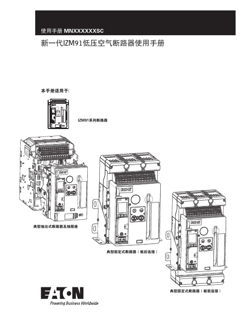
本手册适用于:IZM91系列断路器典型抽出式断路器及抽屉座典型固定式断路器(板后连接)典型固定式断路器(板前连接)新一代IZM91低压空气断路器使用手册使用手册 MNXXXXXXSC目录第一部分:简介. . . . . . . . . . . . . . . . . . . . . . . . . . . . . . . . . . . . . . . . . . . . . . . . . . . . . 1目的 . . . . . . . . . . . . . . . . . . . . . . . . . . . . . . . . . . . . . . . . . . . . . . . . . . . . . . . . . . . . . . . .1安全须知 . . . . . . . . . . . . . . . . . . . . . . . . . . . . . . . . . . . . . . . . . . . . . . . . . . . . . . . . . . . .1具备资格的人员 . . . . . . . . . . . . . . . . . . . . . . . . . . . . . . . . . . . . . . . . . . . . . . . . . . . . . . .1概述 . . . . . . . . . . . . . . . . . . . . . . . . . . . . . . . . . . . . . . . . . . . . . . . . . . . . . . . . . . . . . . . .1产品标签及标识 . . . . . . . . . . . . . . . . . . . . . . . . . . . . . . . . . . . . . . . . . . . . . . . . . . . . . . .2断路器概述 . . . . . . . . . . . . . . . . . . . . . . . . . . . . . . . . . . . . . . . . . . . . . . . . . . . . . . . . . .3抽出式断路器和抽屉座 . . . . . . . . . . . . . . . . . . . . . . . . . . . . . . . . . . . . . . . . . . . . . . . . .3固定式断路器 . . . . . . . . . . . . . . . . . . . . . . . . . . . . . . . . . . . . . . . . . . . . . . . . . . . . . . . .3第二部分:收货、搬运和检查. . . . . . . . . . . . . . . . . . . . . . . . . . . . . . . . . . . . . . . . . . . 8建议使用的工具 . . . . . . . . . . . . . . . . . . . . . . . . . . . . . . . . . . . . . . . . . . . . . . . . . . . . . . .8断路器的拆箱和检查 . . . . . . . . . . . . . . . . . . . . . . . . . . . . . . . . . . . . . . . . . . . . . . . . . . .8断路器的检查 . . . . . . . . . . . . . . . . . . . . . . . . . . . . . . . . . . . . . . . . . . . . . . . . . . . . . . .10断路器的存放 . . . . . . . . . . . . . . . . . . . . . . . . . . . . . . . . . . . . . . . . . . . . . . . . . . . . . . .10第三部分:断路器的一般操作及描述. . . . . . . . . . . . . . . . . . . . . . . . . . . . . . . . . . . . 11概述 . . . . . . . . . . . . . . . . . . . . . . . . . . . . . . . . . . . . . . . . . . . . . . . . . . . . . . . . . . . . . . .11抽出式断路器在抽屉座内的安装 . . . . . . . . . . . . . . . . . . . . . . . . . . . . . . . . . . . . . . . . .11失配联锁保护 . . . . . . . . . . . . . . . . . . . . . . . . . . . . . . . . . . . . . . . . . . . . . . . . . . . . . . .12抽出式断路器的位置 . . . . . . . . . . . . . . . . . . . . . . . . . . . . . . . . . . . . . . . . . . . . . . . . . .12安装固定式断路器 . . . . . . . . . . . . . . . . . . . . . . . . . . . . . . . . . . . . . . . . . . . . . . . . . . . .14断路器的基本组件 . . . . . . . . . . . . . . . . . . . . . . . . . . . . . . . . . . . . . . . . . . . . . . . . . . . .14操作机构 . . . . . . . . . . . . . . . . . . . . . . . . . . . . . . . . . . . . . . . . . . . . . . . . . . . . . . . . . . .14手动操作 . . . . . . . . . . . . . . . . . . . . . . . . . . . . . . . . . . . . . . . . . . . . . . . . . . . . . . . . . . .14电动操作 . . . . . . . . . . . . . . . . . . . . . . . . . . . . . . . . . . . . . . . . . . . . . . . . . . . . . . . . . . .15防跳特性 . . . . . . . . . . . . . . . . . . . . . . . . . . . . . . . . . . . . . . . . . . . . . . . . . . . . . . . . . . .15第四部分:断路器特性和附件. . . . . . . . . . . . . . . . . . . . . . . . . . . . . . . . . . . . . . . . . . 16概述 . . . . . . . . . . . . . . . . . . . . . . . . . . . . . . . . . . . . . . . . . . . . . . . . . . . . . . . . . . . . . . .16灭弧室 . . . . . . . . . . . . . . . . . . . . . . . . . . . . . . . . . . . . . . . . . . . . . . . . . . . . . . . . . . . . .16电子脱扣系统 . . . . . . . . . . . . . . . . . . . . . . . . . . . . . . . . . . . . . . . . . . . . . . . . . . . . . . .16基于微处理器的脱扣器 . . . . . . . . . . . . . . . . . . . . . . . . . . . . . . . . . . . . . . . . . . . . . . . .16额定值插头 . . . . . . . . . . . . . . . . . . . . . . . . . . . . . . . . . . . . . . . . . . . . . . . . . . . . . . . . .16电流互感器 . . . . . . . . . . . . . . . . . . . . . . . . . . . . . . . . . . . . . . . . . . . . . . . . . . . . . . . . .16壳架电流模块 . . . . . . . . . . . . . . . . . . . . . . . . . . . . . . . . . . . . . . . . . . . . . . . . . . . . . . .17脱扣驱动器 . . . . . . . . . . . . . . . . . . . . . . . . . . . . . . . . . . . . . . . . . . . . . . . . . . . . . . . . .17ii新一代IZM91低压空气断路器使用手册 MNXXXXXXSC 2020年12月 使用手册 MNXXXXXXSC固定的高瞬时不可调脱扣 . . . . . . . . . . . . . . . . . . . . . . . . . . . . . . . . . . . . . . . . . . . . . .17非自动装置 . . . . . . . . . . . . . . . . . . . . . . . . . . . . . . . . . . . . . . . . . . . . . . . . . . . . . . . . .17二次端子和接线图 . . . . . . . . . . . . . . . . . . . . . . . . . . . . . . . . . . . . . . . . . . . . . . . . . . . .17一般接线说明 . . . . . . . . . . . . . . . . . . . . . . . . . . . . . . . . . . . . . . . . . . . . . . . . . . . . . . .18附件装置 . . . . . . . . . . . . . . . . . . . . . . . . . . . . . . . . . . . . . . . . . . . . . . . . . . . . . . . . . . .19附件盘 . . . . . . . . . . . . . . . . . . . . . . . . . . . . . . . . . . . . . . . . . . . . . . . . . . . . . . . . . . . . .19左侧附件盘 . . . . . . . . . . . . . . . . . . . . . . . . . . . . . . . . . . . . . . . . . . . . . . . . . . . . . . . . .19右侧附件盘 . . . . . . . . . . . . . . . . . . . . . . . . . . . . . . . . . . . . . . . . . . . . . . . . . . . . . . . . .20分励脱扣器(ST) . . . . . . . . . . . . . . . . . . . . . . . . . . . . . . . . . . . . . . . . . . . . . . . . . . . .20欠压脱扣器(UVR) . . . . . . . . . . . . . . . . . . . . . . . . . . . . . . . . . . . . . . . . . . . . . . . . . .20过电流脱扣开关(OTS) . . . . . . . . . . . . . . . . . . . . . . . . . . . . . . . . . . . . . . . . . . . . . . .20辅助开关 . . . . . . . . . . . . . . . . . . . . . . . . . . . . . . . . . . . . . . . . . . . . . . . . . . . . . . . . . . .20其他内部电气附件 . . . . . . . . . . . . . . . . . . . . . . . . . . . . . . . . . . . . . . . . . . . . . . . . . . . .20弹簧脱扣器(SR) . . . . . . . . . . . . . . . . . . . . . . . . . . . . . . . . . . . . . . . . . . . . . . . . . . .20准备合闸开关(LCS) . . . . . . . . . . . . . . . . . . . . . . . . . . . . . . . . . . . . . . . . . . . . . . . . .20电动马达 . . . . . . . . . . . . . . . . . . . . . . . . . . . . . . . . . . . . . . . . . . . . . . . . . . . . . . . . . . .20机械附件 . . . . . . . . . . . . . . . . . . . . . . . . . . . . . . . . . . . . . . . . . . . . . . . . . . . . . . . . . . .20未联锁的弹出式机械脱扣指示器 . . . . . . . . . . . . . . . . . . . . . . . . . . . . . . . . . . . . . . . . .20联锁的弹出式机械脱扣指示器 . . . . . . . . . . . . . . . . . . . . . . . . . . . . . . . . . . . . . . . . . . .21操作计数器 . . . . . . . . . . . . . . . . . . . . . . . . . . . . . . . . . . . . . . . . . . . . . . . . . . . . . . . . .21断开钥匙锁 . . . . . . . . . . . . . . . . . . . . . . . . . . . . . . . . . . . . . . . . . . . . . . . . . . . . . . . . .21按钮盖 . . . . . . . . . . . . . . . . . . . . . . . . . . . . . . . . . . . . . . . . . . . . . . . . . . . . . . . . . . . . .21安全停止按钮盖 . . . . . . . . . . . . . . . . . . . . . . . . . . . . . . . . . . . . . . . . . . . . . . . . . . . . . .21抽屉座安全挡板 . . . . . . . . . . . . . . . . . . . . . . . . . . . . . . . . . . . . . . . . . . . . . . . . . . . . . .21门框 . . . . . . . . . . . . . . . . . . . . . . . . . . . . . . . . . . . . . . . . . . . . . . . . . . . . . . . . . . . . . . .21IP55 防尘及防水罩 . . . . . . . . . . . . . . . . . . . . . . . . . . . . . . . . . . . . . . . . . . . . . . . . . . .21机械联锁 . . . . . . . . . . . . . . . . . . . . . . . . . . . . . . . . . . . . . . . . . . . . . . . . . . . . . . . . . . .21第五部分:抽出式断路器的安装尺寸图. . . . . . . . . . . . . . . . . . . . . . . . . . . . . . . . . . 22概述 . . . . . . . . . . . . . . . . . . . . . . . . . . . . . . . . . . . . . . . . . . . . . . . . . . . . . . . . . . . . . . .22抽出式抽屉座 . . . . . . . . . . . . . . . . . . . . . . . . . . . . . . . . . . . . . . . . . . . . . . . . . . . . . . .22第六部分:固定式断路器的安装尺寸图 . . . . . . . . . . . . . . . . . . . . . . . . . . . . . . . . . . 35概述 . . . . . . . . . . . . . . . . . . . . . . . . . . . . . . . . . . . . . . . . . . . . . . . . . . . . . . . . . . . . . . .35固定式断路器 . . . . . . . . . . . . . . . . . . . . . . . . . . . . . . . . . . . . . . . . . . . . . . . . . . . . . . .35新一代IZM91低压空气断路器使用手册MNXXXXXXSC 2020年12月 iii使用手册 MNXXXXXXSC第七部分:检查和维护. . . . . . . . . . . . . . . . . . . . . . . . . . . . . . . . . . . . . . . . . . . . . . . 54概述 . . . . . . . . . . . . . . . . . . . . . . . . . . . . . . . . . . . . . . . . . . . . . . . . . . . . . . . . . . . . . . .54一般性建议 . . . . . . . . . . . . . . . . . . . . . . . . . . . . . . . . . . . . . . . . . . . . . . . . . . . . . . . . .54何时检查 . . . . . . . . . . . . . . . . . . . . . . . . . . . . . . . . . . . . . . . . . . . . . . . . . . . . . . . . . . .54检查内容 . . . . . . . . . . . . . . . . . . . . . . . . . . . . . . . . . . . . . . . . . . . . . . . . . . . . . . . . . . .54现场功能测试 . . . . . . . . . . . . . . . . . . . . . . . . . . . . . . . . . . . . . . . . . . . . . . . . . . . . . . .54手动操作功能测试 . . . . . . . . . . . . . . . . . . . . . . . . . . . . . . . . . . . . . . . . . . . . . . . . . . . .55电气操作功能测试 . . . . . . . . . . . . . . . . . . . . . . . . . . . . . . . . . . . . . . . . . . . . . . . . . . . .55脱扣器的测试步骤 . . . . . . . . . . . . . . . . . . . . . . . . . . . . . . . . . . . . . . . . . . . . . . . . . . . .56灭弧栅的检查 . . . . . . . . . . . . . . . . . . . . . . . . . . . . . . . . . . . . . . . . . . . . . . . . . . . . . . .56一次触头检查 . . . . . . . . . . . . . . . . . . . . . . . . . . . . . . . . . . . . . . . . . . . . . . . . . . . . . . .57其他改型和/或更换 . . . . . . . . . . . . . . . . . . . . . . . . . . . . . . . . . . . . . . . . . . . . . . . . . . .57脱扣器的更换 . . . . . . . . . . . . . . . . . . . . . . . . . . . . . . . . . . . . . . . . . . . . . . . . . . . . . . .57电流互感器的更换 . . . . . . . . . . . . . . . . . . . . . . . . . . . . . . . . . . . . . . . . . . . . . . . . . . . .57壳架电流模块的更换 . . . . . . . . . . . . . . . . . . . . . . . . . . . . . . . . . . . . . . . . . . . . . . . . . .57第八部分:故障排除. . . . . . . . . . . . . . . . . . . . . . . . . . . . . . . . . . . . . . . . . . . . . . . . . 58简介 . . . . . . . . . . . . . . . . . . . . . . . . . . . . . . . . . . . . . . . . . . . . . . . . . . . . . . . . . . . . . . .58免责条款及责任限制. . . . . . . . . . . . . . . . . . . . . . . . . . . . . . . . . . . . . . . . . . . . . . . . . 60 iv新一代IZM91低压空气断路器使用手册 MNXXXXXXSC 2020年12月 v新一代IZM91低压空气断路器使用手册 MNXXXXXXSC 2020年12月 警告和小心是本手册操作步骤的一部分,用来保护人员安全和设备不受损坏。
EATON Magnum 说明书 IEC 低压万能式断路器 产品说明书
ESE-LV-ACB-OM-0804
MW1双宽度型万能式断路器使用双宽抽屉座以适应最大 额定值为6300A的需要。水平一次插入式触头和接线端子 作为标准件。可选的垂直端子适配件可供垂直平面的母线 端子优选。以及在独立外壳结构中使用。
MWN 窄型抽屉座 正视图 (带断路器)
MW1 标 准 型 抽 屉 座
4
正视图
后视图 后视图
概述
Magnum 低压万能式断路器为用户提供满足现代配电系统日益增高的综合需要。产品经设计和实验,适用于 额定电压为220/415, 440, 和 500/690AC. 的低压配电设备中。Magnum 断路器适用于抽屉式和固定式安装方式 。三种不同的框架尺寸均具有高额定短路分断能力,无熔断器可至100kA ,其额定电流从800A到6300A。
Magnum 低压断路器的新潮流
伊顿低压断路器影响工业标准已达30多年。始终把可靠性和为顾客服务放在首位,伊顿电气明确地采用IEC标准。 伊顿的新一代万能式断路器体积更小,性能更高,应用范围更广。 Magnum 低压断路器的设计,充分考虑配电设备用户和低压柜厂家的需求,达到最大的使用灵活性。为了取 得最大的安全性,采用了现代化的透门式设计,不用开门就可以直接操作断路器的储能手柄、脱扣单元、控制 单元和关门指示灯。 断路器的高耐压和高分断额定值提供了最大的选择性和系统的配合性,以应对当今电力配电系统的高故障电流。 紧凑、模数化的断路器框架等级使紧凑、经济的结构和通用的外壳成为现实。 电流互感器、额定值插头、脱扣单元和附件,都可以在现场安装更换,不用作整机备用库存。
E-VAC系列中等电压真空断路器产品说明说明书

Ideal contact material and geometry ensure lowchopping current and reliable contact resistanceA few components and compact and reasonable structure ensure morereliable and safer operation Enable ideal cutoff and close of resistance, inductance load and capacitive loadSecondary plug, chassis, moving contact and grounding methods are specially designed ,completely compatible with domestically dominantmedium voltage switchgearProduct modelsE-VAC vacuum circuit breaker120E-VAC(R)i40/3150-210Voltage ratingsE: IEC/GB standardEaton circuit breaker seriesR indicates fixed type,none indicates drawout typei indicates solid-envelope d pole, none indicates assembled polerated short circuit breaking current ratedcurrentphase spacing1E-VAC series medium voltage vacuum circuit breakerProduct descriptionContentsDescription Page 156810E-VAC series medium voltage vacuum circuit breakerProduct description .................................................................Technical data ..........................................................................Dimensions .............................................................................Wiring diagram ........................................................................E-VAC series vacuum circuit breaker selection table ..............E-VAC vacuum circuit breakerProduct descriptionE-VAC Series medium voltage vacuum circuit breakers from Eaton Electrical combine our excellent vacuum technology with decades of experience in designing and manufacturing power distribution system. They offer high reliability, ease of handling and maintenance, high cost efficiency for different customers.Meet IEC, GB and DL standardsE-VAC equipped with new generation vacuum interrupter, suited fortechnologies and operation condition of power system••••••Technical featuresE-VAC utilizes mature spring operating mechanism, offers reliable and stableperformance, long service life, ease of operating,excellent corrosion protection and low maintenance within the lifetimeE-VAC adopts vertical epoxy insulation cover which can prevent harsh environment influence, making E-VAC circuit breaker suitable for various applications. Unique contact material and primary plum-shaped moving contact make E-VAC suitable for medium voltage system in various applications.E2 level electrical life extended and M2 levelmechanical life extended as per standard, capacitivecurrent breaking and making having extremelylowre-breakdown probability C2 level, having completed the type testAll products have been subject to hundreds of mechanical operation running-in tests beforeleaving the factory, ensuring the product performance in the most stable phase Utilize advanced imported testing equipment, exactly record no-load mechanical characteristics of each product, and provide users with these characteristic curves, ensure product reliability2Application conditionAmbient air temperature not exceeding 40℃, and the average value measured within 24 hours not exceeding 35℃. The minimum ambient air temperature is -15℃The effect by solar radiation can be ignoredThe ambient air is notobviously polluted by dust, smoke, corrosive orflammable gases, vapor or salt mistSeismic intensity not exceeding 8 degreeAmplitude of electromagnetic interference induced in secondary system not exceeding 1.6kV•••••••Outline dimension anddistribution panel interlocking method completelycompatible with domestically dominant medium voltage switchgear, high universality, significantly reduce design costProduct assembly utilizes tooling method to ensure dimension consistency. All products have been subject to the push panel test for standard panel, ensuringproduct interchangeability and universality•••••As the manufacturer of theworld’s first vacuum interrupter, the pioneer of vacuumtechnology, Eaton Electrical has been committed to the research, development and manufacturing of vacuum interrupters for over 70 years, and gathered plenty ofexperience. Westinghouse has become the synonym of quality and reliability.We own the world’s largest and globally leading vacuuminterrupter plant and the only vacuum interrupter plant that is equipped with large capacity high voltage laboratories.Our manufacturing capacity and design and development always maintain a leadership position.Application areasTechnology creation historyOptional accessoriesCharging handle Trolley handleLifterE-VAC series medium voltage vacuum circuit breakerProduct descriptionChemical industry Oil industry Piping industry Offshore mining ShipbuildingPaper making industry Opencast coal mine SubstationCement industry Automotive industry Power plantTextile and food industries Metallurgical industry•••••••••••••Temperature conditionThe average of relativehumidity measured within 24 hours not exceeding 95%The average vapor pressure measured within 24 hours not exceeding 2.2kPaThe average of relative humidity measured within one month not exceeding 90%The average vapor pressure measured within one month not exceeding 1.8kPa••••3E-VAC vacuum circuit breaker requires almost no relevant maintenanceIdeal for control and protection in medium voltage power supply and distribution systemSimple structure design of E-VAC vacuum circuit breaker further minimizes faultoccurrence, simplifies daily maintenance. With theindicator on the circuit breaker panel, no detection instrument is required, facilitating the judgment of working state of circuit breaker.The circuit breaker utilizes the world’s first class EatonElectrical’s vacuum interrupter with vacuum degree up to 10-6Pa, low air leakage, and ensure 50-year life with no maintenance required.The circuit breaker is equipped with superior spring charging mechanism, utilizes modular design, offering optimized mechanism main partdistribution, simpler structure and more reliable performance. The whole mechanism is composed by three modules: charging, closing, opening. Assembly and maintenance of these three parts are very simple. The spring charging mechanism composed by ratchet wheel mechanism,oscillator and closing spring is compact and smart. Theoperating mechanism is usually equipped with manual charging device and electric charging device, enabling automatic reclosing function.The circuit for manual charging operating mechanism isprovided with manual opening and closing operation buttons, circuit breaker position indicator and spring mechanism charging status indicator, switch operations counter, shunt release auxiliary switch, position and fault signals, etc..The circuit breaker of electric charging operating mechanism: added with spring charging motor, shunt release, trip free relay, and auxiliary switch for spring charging motor release.The following accessories can also be provided as needed: undervoltage release,overcurrent relay, etc..E-VAC series medium voltage vacuum circuit breakerProduct description4Main specification and technical parametersItem Unit Value Technical parameters for trip/close coilsNameParameter Note: (1)forced air cooling is required at 4000A; (2) If the user has special requirements, up to 125kA.O-0.3s-CO-180s-CO, O-180s-CO-180s-CO(50kA)5Technical dataE-VAC series medium voltage vacuum circuit breakerT echnical dataRated operating sequenceCharging duration Rated power of spring charging motor Rated voltage of spring charging motor Rated opening operating voltage Rated closing operating voltage Allowable accumulated wearingthickness of moving/fixed contact Rated short circuit current breaking cycleRated current breaking cycleMechanical lifeClosing time Opening time Secondary circuit power frequency withstand voltage (1 min)Rated short circuit making currentRated peak withstand current Rated currentRated frequency Rated lightning impulse withstand voltage (peak)Rated short-time power frequency withstand voltage (1 min)Rated voltageRated short-circuit breaking current Rated short-time withstand current (4s)Hz A kVkA kA kA kA V ms ms Cycle Cycle Cycle mm V V W s1242(phase to ground, phase to phase) 48 (gap)75 (phase to ground, phase to phase) 85(gap)506301250630 12501600 20001250 16002000 25003150 4000(1)1250 16002000 25003150 4000(1)252531.531.54040505063638080100(2)100(2)125130200020~5035~7020000, (10000 cycles at 50kA)20000, (10000 cycles at 50kA)E2(274)3AC 110/220AC 110/22065, (80W at 50kA)≤15DC 110/220V AC 110/220 DC 110/220DC 110/220Normal working voltage rangeRated working voltage (V)Rated working current of close coil (A)Rated working current of trip coil (A)AC, DC110AC, DC2202.0 1.01.80.9Closing: 80%~110% of rated working voltageOpening: 65%~120% of rated working voltage, opening will not occur when the normal working voltage is less than 30% of rated working voltageOutline and dimension of E-VAC circuit breaker (drawout type)Rated short circuit breaking current (kA)Rated current (A)Distribution panelwidth(mm)W S R N M L K J G F E D C B A H P T 6E-VAC series medium voltage vacuum circuit breakerDimensionsDimensions80080080080010001000100010001000630125016001250630125016001600~20002500~400020~31.520~4031.540(Short-circuit 125)20~31.520~4031.531.5~5031.5~50210210210275275275275275275275275275310275275275310310638638638638838838838838838652652652652852852852852852640640640640838838838838838650650650650850850850850850433433433361433433433361361626626626680626626626680680354955793549557910928028028029528028028029529559859859858659859859858658676767677767676777778787888787878888863763763769863763763769869850850850853650850850853653627727727727737737737737737740404004040400023232319313131313180010001000630~1600630~16001600~4000275275210310275275650720520720720520770770588632580580786590IIIII I 275275250252237237465455455Outline and dimension of E-VACR circuit breaker (fixed type)Note: during installation, make sure copper busbar reliably contacts the conductive surface of circuit breaker outlet in free state. Do not exert external force on the copper busbar to adjust its shape. Forced installation is not allowed!Distribution panel width Rated current (A)P H A B C E F G1\G2I J K 7E-VAC series medium voltage vacuum circuit breakerDimensionsE-VAC series medium voltage vacuum circuit breakerWiring diagramWiring diagramSecondary control connection diagram of E-VAC series vacuum circuit breaker (drawout type)The diagram shows the circuit breaker in test position, opening, discharged states8E-VAC series medium voltage vacuum circuit breakerWiring diagramSecondary control connection diagram of E-VACR series vacuum circuit breaker (fixed type) The diagram shows the circuit breaker in opening, discharged states9E-VAC series vacuum circuit breaker selection table1. Circuit breaker models2. Parameters of E-VAC series vacuum circuit breaker3. Technical parameters of spring operating mechanism4. Optional configuration (Standard option includes trip free device. Please note if the trip free device has to been canceled)E-VAC (drawout type)□E-VACR (fixed t ype)□Note: Technical parameters of products will be changed without notice. Please confirm with Eaton Corporation before ordering.10E-VAC series medium voltage vacuum circuit breakerE-VAC series vacuum circuit breaker selection tableParameters NameParameters NameName800Panel width(mm)Breaker phase spacing(mm)Rated short circuit breaking current (kA)(kA)Rated working current (A)21010002752531.540(Short-circuit 100kA )40(Short-circuit 125kA )31.54050□630□630□1250□1250□1250□1250□1600□1600□2000□1600□2000□2500□1600□2000□2500□3150□4000*□3150□4000** Forced air cooling is required at 4000AOpening power supply (V)Closing power supply (V)Spring charging motor power supply (V)□DC110□DC110□DC110□AC110□AC110□AC110□DC220□DC220□DC220□AC220□AC220□AC220□Overcurrent release □Closing latch □Position latch □Trip free relay □Undervoltage release □Operating handle□2 Overcurrent □3 Overcurrent□A□V □V □V □V□Quantity neededEaton is dedicated to ensuring that reliable, efficient and safe power is available when it’s needed most. With unparalleled knowledge of electrical power management across industries, experts at Eaton deliver customized, integrated solutions to solve our customers’ most critical challenges.Our focus is on delivering the right solution for the application. But, decision makers demand more than just innovative products. They turn to Eaton for an unwavering commitment to personal support that makes customer success a top priority. For more information,visit /seasia-electrical.Electrical Sector Asia PacificNo.3, Lane 280, Linhong Road,Changning District, ShanghaiEaton Industries Pte LtdElectrical Sector4 Loyang Lane #04-01/02Singapore 508914/seasia-electrical© 2013 Eaton Corporation All Rights Reserved Printed in SingaporeJuly 2013Eaton is a registered trademarkof Eaton Corporation.All trademarks are property of their respective owners.。
Eaton电能保护系列产品说明书

3
2
2d
2
P2
1
2.4 Nm
(21 lb-in)
4 PD4-4P
1
2
en For 4 poles only
zh 仅适用于4极
6
Charged
OFF
4
8X
EATON IL012369EN
3
7
en If Remote Operator was charged. Only when the Remote Operator installation is complete, Button I can be pushed.
2
EATON IL012369EN
1
2
P2
3
2.4 Nm
(21 lb-in)
Drill Location
PDG4XROP.../ PDE4XROP...
unit : inch
2c
3 1
2
P2 2.4 Nm (21 lb-in) #8-32 by 2.5”
5
1
Discharged
OFF
Manual Auto
1 x 0.5 - 2.5 mm2 1 x AWG20 - AWG12
0.5 Nm (4.42 lb-in)
b
Parallel connection between two remote operators
电操联锁并联电路
H = Signal lamp 0 = Pushbutton or contact for opening the circuit-breaker I = Pushbutton or contact for switch closing
美国EATON公司保护设备系列微型断路器PLS4、PLZ4(MW)产品说明说明书
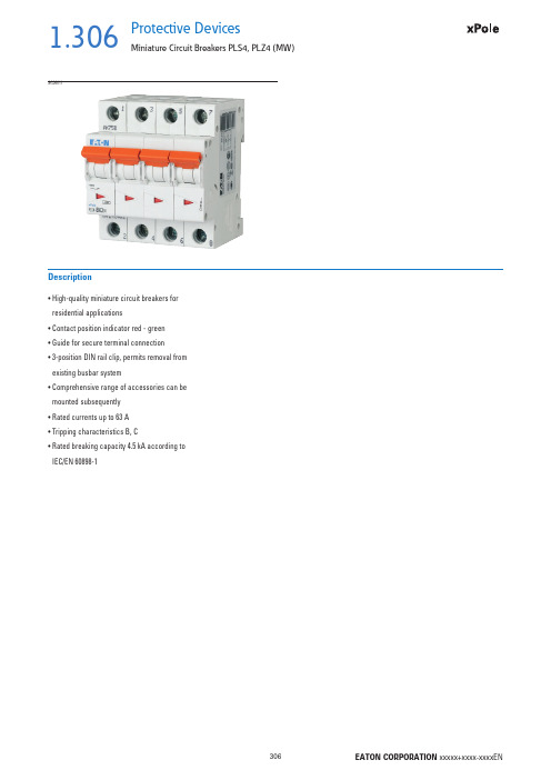
1.306Protective DevicesMiniature Circuit Breakers PLS4, PLZ4 (MW)• H igh-quality miniature circuit breakers for residential applications• Contact position indicator red - green • Guide for secure terminal connection • 3-position DIN rail clip, permits removal from existing busbar system• C omprehensive range of accessories can be mounted subsequently • Rated currents up to 63 A • Tripping characteristics B, C• R ated breaking capacity 4.5 kA according to IEC/EN 60898-1DescriptionSG360111.307Protective DevicesMiniature Circuit Breakers PLS4, PLZ4 (MW)Rated current I n (A)TypeDesignationArticle No.Units perpackage4.5 kA, Characteristic BSG284111PLS4-B124314112/1201.5PLS4-B1,524314212/1201.6PLS4-B1,624314312/1202PLS4-B224314412/1202.5PLS4-B2,524314512/1203PLS4-B324314612/1203.5PLS4-B3,524314712/1204PLS4-B424314812/1205PLS4-B524314912/1206PLS4-B624315012/1208PLS4-B824315112/12010PLS4-B1024315212/12012PLS4-B1224315312/12013PLS4-B1324315412/12015PLS4-B1524315512/12016PLS4-B1624315612/12020PLS4-B2024315712/12025PLS4-B2524315812/12032PLS4-B3224315912/12040PLS4-B4024316012/12050PLS4-B5024316112/12063PLS4-B6324316212/1201-poleSG207111PLZ4-B1/1N2431891/601.5PLZ4-B1,5/1N2431901/601.6PLZ4-B1,6/1N2431911/602PLZ4-B2/1N2431921/602.5PLZ4-B2,5/1N2431931/603PLZ4-B3/1N2431941/603.5PLZ4-B3,5/1N2431951/604PLZ4-B4/1N2431961/605PLZ4-B5/1N2431971/606PLZ4-B6/1N2431981/608PLZ4-B8/1N2431991/6010PLZ4-B10/1N2432001/6012PLZ4-B12/1N2432011/6013PLZ4-B13/1N2432021/6015PLZ4-B15/1N2432031/6016PLZ4-B16/1N2432041/6020PLZ4-B20/1N2432051/6025PLZ4-B25/1N2432061/6032PLZ4-B32/1N2432071/6040PLZ4-B40/1N2432081/6050PLZ4-B50/1N2432091/6063PLZ4-B63/1N2432101/601+N-pole 2MU1.308Protective DevicesMiniature Circuit Breakers PLS4, PLZ4 (MW)Rated current I n (A)TypeDesignationArticle No.Units perpackage SG229111PLS4-B1/22432371/601.5PLS4-B1,5/22432381/601.6PLS4-B1,6/22432391/602PLS4-B2/22432401/602.5PLS4-B2,5/22432411/603PLS4-B3/22432421/603.5PLS4-B3,5/22432431/604PLS4-B4/22432441/605PLS4-B5/22432451/606PLS4-B6/22432461/608PLS4-B8/22432471/6010PLS4-B10/22432481/6012PLS4-B12/22432491/6013PLS4-B13/22432501/6015PLS4-B15/22432511/6016PLS4-B16/22432521/6020PLS4-B20/22432531/6025PLS4-B25/22432541/6032PLS4-B32/22432551/6040PLS4-B40/22432561/6050PLS4-B50/22432571/6063PLS4-B63/22432581/602-poleSG314111PLS4-B1/32432851/401.5PLS4-B1,5/32432861/401.6PLS4-B1,6/32432871/402PLS4-B2/32432881/402.5PLS4-B2,5/32432891/403PLS4-B3/32432901/403.5PLS4-B3,5/32432911/404PLS4-B4/32432921/405PLS4-B5/32432931/406PLS4-B6/32432941/408PLS4-B8/32432951/4010PLS4-B10/32432961/4012PLS4-B12/32432971/4013PLS4-B13/32432981/4015PLS4-B15/32432991/4016PLS4-B16/32433001/4020PLS4-B20/32433011/4025PLS4-B25/32433021/4032PLS4-B32/32433031/4040PLS4-B40/32433041/4050PLS4-B50/32433051/4063PLS4-B63/32433061/403-pole1.309Protective DevicesMiniature Circuit Breakers PLS4, PLZ4 (MW)Rated current I n (A)TypeDesignationArticle No.Units perpackage SG352111PLS4-B1/3N2433331/301.5PLS4-B1,5/3N2433341/301.6PLS4-B1,6/3N2433351/302PLS4-B2/3N2433361/302.5PLS4-B2,5/3N2433371/303PLS4-B3/3N2433381/303.5PLS4-B3,5/3N2433391/304PLS4-B4/3N2433401/305PLS4-B5/3N2433411/306PLS4-B6/3N2433421/308PLS4-B8/3N2433431/3010PLS4-B10/3N2433441/3012PLS4-B12/3N2433451/3013PLS4-B13/3N2433461/3015PLS4-B15/3N2433471/3016PLS4-B16/3N2433481/3020PLS4-B20/3N2433491/3025PLS4-B25/3N2433501/3032PLS4-B32/3N2433511/3040PLS4-B40/3N2433521/3050PLS4-B50/3N2433531/3063PLS4-B63/3N2433541/303+N-poleSG371111PLS4-B1/42433811/301.5PLS4-B1,5/42433821/301.6PLS4-B1,6/42433831/302PLS4-B2/42433841/302.5PLS4-B2,5/42433851/303PLS4-B3/42433861/303.5PLS4-B3,5/42433871/304PLS4-B4/42433881/305PLS4-B5/42433891/306PLS4-B6/42433901/308PLS4-B8/42433911/3010PLS4-B10/42433921/3012PLS4-B12/42433931/3013PLS4-B13/42433941/3015PLS4-B15/42433951/3016PLS4-B16/42433961/3020PLS4-B20/42433971/3025PLS4-B25/42433981/3032PLS4-B32/42433991/3040PLS4-B40/42434001/3050PLS4-B50/42434011/3063PLS4-B63/42434021/304-pole1.310Protective DevicesMiniature Circuit Breakers PLS4, PLZ4 (MW)Rated current I n (A)TypeDesignationArticle No.Units perpackage4.5 kA, Characteristic CSG284110.16PLS4-C0.1624316312/1200.25PLS4-C0,2524316412/1200.5PLS4-C0,524316612/1200.75PLS4-C0,7524316512/1201PLS4-C124316712/1201.5PLS4-C1,524316812/1201.6PLS4-C1,624316912/1202PLS4-C224317012/1202.5PLS4-C2,524317112/1203PLS4-C324317212/1203.5PLS4-C3,524317312/1204PLS4-C424317412/1205PLS4-C524317512/1206PLS4-C624317612/1208PLS4-C824317712/12010PLS4-C1024317812/12012PLS4-C1224317912/12013PLS4-C1324318012/12015PLS4-C1524318112/12016PLS4-C1624318212/12020PLS4-C2024318312/12025PLS4-C2524318412/12032PLS4-C3224318512/12040PLS4-C4024318612/12050PLS4-C5024318712/12063PLS4-C6324318812/1201-poleSG207110.16PLZ4-C0.16/1N2432111/600.25PLZ4-C0,25/1N2432121/600.5PLZ4-C0,5/1N2432141/600.75PLZ4-C0,75/1N2432131/601PLZ4-C1/1N2432151/601.5PLZ4-C1,5/1N2432161/601.6PLZ4-C1,6/1N2432171/602PLZ4-C2/1N2432181/602.5PLZ4-C2,5/1N2432191/603PLZ4-C3/1N2432201/603.5PLZ4-C3,5/1N2432211/604PLZ4-C4/1N2432221/605PLZ4-C5/1N2432231/606PLZ4-C6/1N2432241/608PLZ4-C8/1N2432251/6010PLZ4-C10/1N2432261/6012PLZ4-C12/1N2432271/6013PLZ4-C13/1N2432281/6015PLZ4-C15/1N2432291/6016PLZ4-C16/1N2432301/6020PLZ4-C20/1N2432311/6025PLZ4-C25/1N2432321/6032PLZ4-C32/1N2432331/6040PLZ4-C40/1N2432341/6050PLZ4-C50/1N2432351/6063PLZ4-C63/1N2432361/601+N-pole 2MU1.311Protective DevicesMiniature Circuit Breakers PLS4, PLZ4 (MW)Rated current I n (A)TypeDesignationArticle No.Units perpackage SG229110.16PLS4-C0.16/22432591/600.25PLS4-C0,25/22432601/600.5PLS4-C0,5/22432621/600.75PLS4-C0,75/22432611/601PLS4-C1/22432631/601.5PLS4-C1,5/22432641/601.6PLS4-C1,6/22432651/602PLS4-C2/22432661/602.5PLS4-C2,5/22432671/603PLS4-C3/22432681/603.5PLS4-C3,5/22432691/604PLS4-C4/22432701/605PLS4-C5/22432711/606PLS4-C6/22432721/608PLS4-C8/22432731/6010PLS4-C10/22432741/6012PLS4-C12/22432751/6013PLS4-C13/22432761/6015PLS4-C15/22432771/6016PLS4-C16/22432781/6020PLS4-C20/22432791/6025PLS4-C25/22432801/6032PLS4-C32/22432811/6040PLS4-C40/22432821/6050PLS4-C50/22432831/6063PLS4-C63/22432841/602-poleSG314110.16PLS4-C0.16/32433071/400.25PLS4-C0,25/32433081/400.5PLS4-C0,5/32433101/400.75PLS4-C0,75/32433091/401PLS4-C1/32433111/401.5PLS4-C1,5/32433121/401.6PLS4-C1,6/32433131/402PLS4-C2/32433141/402.5PLS4-C2,5/32433151/403PLS4-C3/32433161/403.5PLS4-C3,5/32433171/404PLS4-C4/32433181/405PLS4-C5/32433191/406PLS4-C6/32433201/408PLS4-C8/32433211/4010PLS4-C10/32433221/4012PLS4-C12/32433231/4013PLS4-C13/32433241/4015PLS4-C15/32433251/4016PLS4-C16/32433261/4020PLS4-C20/32433271/4025PLS4-C25/32433281/4032PLS4-C32/32433291/4040PLS4-C40/32433301/4050PLS4-C50/32433311/4063PLS4-C63/32433321/403-pole1.312Protective DevicesMiniature Circuit Breakers PLS4, PLZ4 (MW)Rated current I n (A)TypeDesignationArticle No.Units perpackage SG352110.16PLS4-C0.16/3N2433551/300.25PLS4-C0,25/3N2433561/300.5PLS4-C0,5/3N2433581/300.75PLS4-C0,75/3N2433571/301PLS4-C1/3N2433591/301.5PLS4-C1,5/3N2433601/301.6PLS4-C1,6/3N2433611/302PLS4-C2/3N2433621/302.5PLS4-C2,5/3N2433631/303PLS4-C3/3N2433641/303.5PLS4-C3,5/3N2433651/304PLS4-C4/3N2433661/305PLS4-C5/3N2433671/306PLS4-C6/3N2433681/308PLS4-C8/3N2433691/3010PLS4-C10/3N2433701/3012PLS4-C12/3N2433711/3013PLS4-C13/3N2433721/3015PLS4-C15/3N2433731/3016PLS4-C16/3N2433741/3020PLS4-C20/3N2433751/3025PLS4-C25/3N2433761/3032PLS4-C32/3N2433771/3040PLS4-C40/3N2433781/3050PLS4-C50/3N2433791/3063PLS4-C63/3N2433801/303+N-poleSG371110.16PLS4-C0.16/42434031/300.25PLS4-C0,25/42434041/300.5PLS4-C0,5/42434061/300.75PLS4-C0,75/42434051/301PLS4-C1/42434071/301.5PLS4-C1,5/42434081/301.6PLS4-C1,6/42434091/302PLS4-C2/42434101/302.5PLS4-C2,5/42434111/303PLS4-C3/42434121/303.5PLS4-C3,5/42434131/304PLS4-C4/42434141/305PLS4-C5/42434151/306PLS4-C6/42434161/308PLS4-C8/42434171/3010PLS4-C10/42434181/3012PLS4-C12/42434191/3013PLS4-C13/42434201/3015PLS4-C15/42434211/3016PLS4-C16/42434221/3020PLS4-C20/42434231/3025PLS4-C25/42434241/3032PLS4-C32/42434251/3040PLS4-C40/42434261/3050PLS4-C50/42434271/3063PLS4-C63/42434281/304-pole1.313Protective DevicesMiniature Circuit Breakers PLS..., PLZ... - T echnical DataSpecifi cations | Miniature Circuit Breakers PLS..., PLZ...Description• High selectivity between MCB and back-up fuse due to low let-throughenergy• Compatible with standard busbar• T win-purpose terminal (lift/open-mouthed) above and below• B usbar positioning optionally above or below• M eets the requirements of insulation co-ordination, distance between con-tacts ≥ 4 mm, for secure isolation• S uitable for applications up to 48 V DC (use PLS6-DC for higher DC voltages)Accessories:Auxiliary switch for subsequent installation ZP-IHK286052ZP-WHK286053Tripping signal switch for subsequent installation ZP-NHK248437Remote control and automatic switching device Z-FW/LP248296Shunt trip release ZP-ASA/..248438, 248439Undervoltage release Z-USA/..248288-248291Compact enclosure KLV-TC-2276240KLV-TC-4276241Additional terminal 35 mm2Z-HA-EK/35263960Switching interlock Z-IS/SPE-1TE274418Technical DataPLS..., PLZ...ElectricalDesign according toIEC/EN 60898-1Current test marks as printed onto the deviceRated voltage U n AC: 230/400 VDC: 48 V (per pole, max. 2 poles)Rated frequency50/60 HzRated breaking capacity according to IEC/EN 60898-1I cnPLSM, PLZM10 kAPLS6, PLZ6 6 kAPLS4, PLZ4 4.5 kACharacteristic B, C, DBack-up fusePLSM, PLZM max. 125 A gLPLS6, PLZ6max. 100 A gLPLS4, PLZ4max. 80 A gLSelectivity class3Enduranceelectrical components≥ 10,000 switching operationsmechanical components≥ 20,000 switching operationsLine voltage connection at will (above/below)MechanicalFrame size45 mmDevice height80 mmDevice width17.5 mm per pole (1MU)26.3 mm: device 1P+N (1.5MU)Mounting quick fastening with 3 lock-in positions on DIN rail IEC/EN 60715Degree of protection IP20Upper and lower terminals open mouthed/lift terminalsTerminal protection fi nger and hand touch safe, DGUV VS3, EN 50274Terminal capacity1-25 mm2(1p+N, 1,5TE)1-25 mm2 / 1-16 mm2 (N)Terminal torque2-2.4 Nm(1p+N, 1,5TE)2-2.4 Nm / 1.2-1.5 Nm (N)Busbar thickness 0.8 - 2 mm (except N 0.5MU)Mounting independent of position1.314Protective DevicesMiniature Circuit Breakers PLS..., PLZ... - T echnical DataConnection diagrams1-pole 1+N-pole(1.5MU)1+N-pole(2MU)2-pole3-pole 3+N-pole4-poleDimensions (mm)3 3 1 7(33 1 33 1 7( 3Tripping Characteristics (IEC/EN 60898-1)1+N-pole (1.5MU)1+N-pole (2MU)Quick-acting (B), slow (C), very slow (D)Tripping characteristic B Tripping characteristic C Tripping characteristic D TRIPPING CURRENT TRIPPING CURRENT TRIPPING CURRENT1.315Protective DevicesMiniature Circuit Breakers PLS..., PLZ... - T echnical Data Effect of the Ambient Temperature on Thermal Tripping Behaviour Effect of Power FrequencyEffect of power frequency on the tripping behaviour I MA of the quick releaseLoad Capacity of Series Connected Miniature Circuit BreakersPower frequency f [Hz]162/35060100200300400I MA (f)/I MA (50 Hz) [%]91100101106115134141Adjusted rated current values according to the ambient temperatureNumber of devices (n) 1-pole1.325Protective DevicesMiniature Circuit Breakers PLS4 - T echnical Data Let-through Energy PLS4Let-through Energy PLS4, Characteristic B, 1-poleLet-through Energy PLS4, Characteristic C, 1-poleShort Circuit Selectivity PLS4 towards DII-DIV fuse linkIn case of short circuit, there is selectivity between the miniature circuit breakers PLS4 and the upstream fuses up to the specifi ed values of the selectivity limit current I s [kA] (i. e. in case of short-circuit currents I ks under I s only the MCB will trip, in case of short circuit currents above this value both protective devices will respond).*) basically in accordance with EN 60898-1 D.5.2.bShort circuit selectivity Characteristic B towards fuse link DII-DIV *)Short circuit selectivity Characteristic C towards fuse link DII-DIV*)PLS4DII-DIV gL/gG I n [A]10162025355063801001.0<0.51) 1.2 4.52) 4.52) 4.52) 4.52) 4.52) 4.52) 4.52)1.5<0.51) 1.0 4.52) 4.52) 4.52) 4.52) 4.52) 4.52) 4.52)2.0<0.51)<0.51)0.8 1.6 4.52) 4.52) 4.52) 4.52) 4.52)2.5<0.51)<0.51)0.8 1.5 4.52) 4.52) 4.52) 4.52) 4.52)3.0<0.51)<0.51)0.8 1.4 4.52) 4.52) 4.52) 4.52) 4.52)3.5<0.51)<0.51)0.7 1.3 4.52) 4.52) 4.52) 4.52) 4.52)4<0.51)<0.51)0.6 1.0 3.6 4.52) 4.52) 4.52) 4.52)1)1)2)2)2)PLS4DII-DIV gL/gG I n [A]10162025355063801000.75 1.0 4.52) 4.52) 4.52) 4.52) 4.52) 4.52) 4.52) 4.52)1.0<0.51) 1.2 4.52) 4.52) 4.52) 4.52) 4.52) 4.52) 4.52)1.5<0.51)<0.51) 1.0 2.2 4.52) 4.52) 4.52) 4.52) 4.52)2.0<0.51)<0.51)0.8 1.6 4.52) 4.52) 4.52) 4.52) 4.52)2.5<0.51)<0.51)0.8 1.4 4.52) 4.52) 4.52) 4.52) 4.52)3.0<0.51)<0.51)0.80.9 4.52) 4.52) 4.52) 4.52) 4.52)3.5<0.51)<0.51)0.60.9 2.2 4.52) 4.52) 4.52) 4.52)4<0.51)<0.51)0.60.8 1.8 3.6 4.52) 4.52) 4.52)1)1)2)2)2)1) Selectivity limit current I sunder 0.5 kA2) S electivity limit current I s = rated breaking capacity I cn of the MCBDarker areas: no selectivityProspective short-circuit current [A]L e t t h r o u g h e n e r g y I 2t [A 2 s e c ]Prospective short-circuit current [A]L e t t h r o u g h e n e r g y I 2t [A 2 s e c ]1.326Protective DevicesMiniature Circuit Breakers PLS4 - T echnical DataShort Circuit Selectivity PLS4 towards D01-D03 fuse linkIn case of short circuit, there is selectivity between the miniature circuit breakers PLS4 and the upstream fuses up to the specifi ed values of the selectivity limit current I s [kA] (i. e. in case of short-circuit currents I ks under I s only the MCB will trip, in case of short circuit currents above this value both protective devices will respond).*) basically in accordance with EN 60898-1 D.5.2.bShort circuit selectivity Characteristic B towards fuse link D01-D03*)Short circuit selectivity Characteristic C towards fuse link D01-D03*)PLS4D01-D03 gL/gG I n [A]10162025355063801001.0<0.51) 4.52) 4.52) 4.52) 4.52) 4.52) 4.52) 4.52) 4.52)1.5<0.51) 4.1 4.52) 4.52) 4.52) 4.52) 4.52) 4.52) 4.52)2.0<0.51)<0.51)0.6 1.0 4.52) 4.52) 4.52) 4.52) 4.52)2.5<0.51)<0.51)0.6 1.0 4.52) 4.52) 4.52) 4.52) 4.52)3.0<0.51)<0.51)0.5 1.0 4.52) 4.52) 4.52) 4.52) 4.52)3.5<0.51)<0.51)0.50.9 4.52) 4.52) 4.52) 4.52) 4.52)1)1)2)2)2)2)PLS4D01-D03 gL/gG I n [A]10162025355063801000.75<0.51) 4.52) 4.52) 4.52) 4.52) 4.52) 4.52) 4.52) 4.52)1.0<0.51) 4.52) 4.52) 4.52) 4.52) 4.52) 4.52) 4.52) 4.52)1.5<0.51)0.50.60.9 4.52) 4.52) 4.52) 4.52) 4.52)2.0<0.51)<0.51)0.50.7 4.52) 4.52) 4.52) 4.52) 4.52)2.5<0.51)<0.51)0.50.7 4.52) 4.52) 4.52) 4.52) 4.52)3.0<0.51)<0.51)<0.51)0.6 1.9 4.52) 4.52) 4.52) 4.52)3.5<0.51)<0.51)<0.51)0.6 1.8 4.52) 4.52) 4.52) 4.52)1)1)1)2)2)2)Short circuit selectivity Characteristic B towards fuse link NH-00*)Short circuit selectivity Characteristic C towards fuse link NH-00*)PLS4NH-00 gL/gG I n [A]1620253235405063801001251601.00.9 4.52) 4.52) 4.52) 4.52) 4.52) 4.52) 4.52) 4.52) 4.52) 4.52) 4.52)1.50.8 4.52) 4.52) 4.52) 4.52) 4.52) 4.52) 4.52) 4.52) 4.52) 4.52) 4.52)2.0<0.51)0.5 1.0 2.5 4.52) 4.52) 4.52) 4.52) 4.52) 4.52) 4.52) 4.52)2.5<0.51)0.5 1.0 2.3 4.52) 4.52) 4.52) 4.52) 4.52) 4.52) 4.52) 4.52)3.0<0.51)0.50.9 2.1 4.52) 4.52) 4.52) 4.52) 4.52) 4.52) 4.52) 4.52)3.5<0.51)0.50.9 1.8 4.52) 4.52) 4.52) 4.52) 4.52) 4.52) 4.52) 4.52)4<0.51)<0.51)0.8 1.3 2.3 4.3 4.52) 4.52) 4.52) 4.52) 4.52) 4.52)5<0.51)<0.51)0.7 1.1 1.6 2.2 3.6 4.52) 4.52) 4.52) 4.52) 4.52)6<0.51)<0.51)0.7 1.1 1.5 2.0 3.3 4.3 4.52) 4.52) 4.52) 4.52)1)<0.51)0.61.0 1.3 1.72.63.34.52) 4.52) 4.52) 4.52)PLS4NH-00 gL/gG I n [A]1620253235405063801001251600.75 4.52) 4.52) 4.52) 4.52) 4.52) 4.52) 4.52) 4.52) 4.52) 4.52) 4.52) 4.52)1.00.9 4.52) 4.52) 4.52) 4.52) 4.52) 4.52) 4.52) 4.52) 4.52) 4.52) 4.52)1.5<0.51)0.6 1.3 4.2 4.52) 4.52) 4.52) 4.52) 4.52) 4.52) 4.52) 4.52)2.0<0.51)0.6 1.0 2.5 4.52) 4.52) 4.52) 4.52) 4.52) 4.52) 4.52) 4.52)2.5<0.51)0.5 1.0 2.1 4.52) 4.52) 4.52) 4.52) 4.52) 4.52) 4.52) 4.52)3.0<0.51)<0.51)0.7 1.2 1.8 2.6 4.52) 4.52) 4.52) 4.52) 4.52) 4.52)3.5<0.51)<0.51)0.7 1.1 1.7 2.4 4.2 4.52) 4.52) 4.52) 4.52) 4.52)4<0.51)<0.51)0.7 1.0 1.5 2.1 3.6 4.52) 4.52) 4.52) 4.52) 4.52)5<0.51)<0.51)0.60.8 1.2 1.7 2.8 3.8 4.52) 4.52) 4.52) 4.52)6<0.51)<0.51)0.50.8 1.2 1.5 2.5 3.3 4.52) 4.52) 4.52) 4.52)1)<0.51)0.50.8 1.1 1.5 2.3 2.9 4.52) 4.52) 4.52) 4.52)。
伊顿电动机断路保护器(PDF精品)
电动机保护断路器1电动机保护断路器PKZ电动机保护断路器PKE电动机保护断路器PKZMC1.11.2xStart 系列电动机保护断路器电动机保护断路器PKZ . . . . . . . . . . . . . . . . . . . . . . . . . . . . . . . . . . . . . . . . . . . . . . . . . . . .电动机保护断路器PKE . . . . . . . . . . . . . . . . . . . . . . . . . . . . . . . . . . . . . . . . . . . . . . . . . . . .xStart C 系列电动机保护断路器电动机保护断路器PKZMC . . . . . . . . . . . . . . . . . . . . . . . . . . . . . . . . . . . . . . . . . . . . . . . . .3847电动机保护断路器PKZM01、PKZM0、PKZM4、PKE1.11机械及装置的停机时间应尽可能缩短。
PKZ 无熔断器式电动机保护断路器在一个装置内整合了短路和过载保护,可随时准备快速重起。
PKZM01、PKZM0、PKZM4和PKE 均采用相同附件,并且易与DILM (C)接触器和DS7软起动器组合使用。
此外,PKE 连接至SmartWire-DT ®,有助于提高数据透明性。
电动机保护断路器位于外壳内,防护等级可达IP40和IP65。
内置紧急停车和停机关闭按钮,从而减少接线量。
••带按钮的PKZM01(高达25 A )电动机保护断路器高达50kA 及以上的防短路保护,易于工程操作。
脱扣指示触点确保远程诊断。
••作为主开关或维护及维修开关应用,安全性高。
ATEX 认证,保护高达65A 的EEx e 电动机。
••带旋转手柄的PKZM0(高达32 A )和PKZM4(高达65 A )电动机保护断路器插入式脱扣单元块,灵活性高。
Eaton 商业控制设备通用推按开关说明书
Eaton®Commercial Controls DivisionGeneral Purpose — AC Rated. . . . . . . . . . . . . . . . . . . . . . 3.2General Purpose Illuminated — AC/DC Rated. . . . . . . . . . 3.63 Pushbutton SwitchesThe Power of Reliability3.13.2Type RatingPoles and ThrowContacts Typical Maximum Operating Force 1 P.S.T . NC A Nylon Black 11.50 .453″ 0.7 lbs.W — Flush — 8410K1 — —1 P.S.T . NC A Nylon Black 11.89 .468″ 0.7 lbs.W — Flush — 8406K1 — —1 P.S.T . NC A Nylon White 9.53 .375″ — — Snap-In — — 8423K1 Q —1 P.S.T . NO A Nylon White 9.53 .375″ — — Snap-In — — 8424K1 Q —1 P .S.T . NC ANylon Black 6.35 .250″ 1.5 lbs. W 6.35 .250″ 8411K5 — — —1 P .S.T . NO Nylon Red 6.35 .250″ 1.5 lbs. E 6.35 .250″ — — 8411K13Q —1 P .S.T . NC ANylon Black 10.31 .406″ 1.5 lbs. W 11.89 .468″ 8411K8 8411K7 8411K10 —1 P .S.T . NO Nylon Black 9.53 .375″ 1.5 lbs. E 11.89 .468″ — 8411K12 8411K11Q —1 P .S.T . NC ANylon Black 6.35 .250″ 1.5 lbs. 6.35 .250″ — — 8418K1 Q —1 P .S.T . NO Nylon Black 10.31 .406″ 1.5 lbs. 11.89 .468″ — — 8418K12 Q —1 P .S.T . NO A Metal — 7.52 .296″ 2.5 lbs. 11.89 .468″ 8440K2 8440K3 — —Metal — 7.92 .312″ — 14.27 .562″ 7835K11A — — 7835K12A Nylon Black — — — 14.27 .562″ 7835K11C — — —1 P .S.T . NC A (Snap-On)Nylon Red — — — 14.27 .562″ 7835K11D — — —(Snap-On)Metal — 7.92 .312″ — 14.27 .562″ 7836K11A 7836K13A — 7836K12A Nylon Black — — — 14.27 .562″ 7836K11C ———1 P .S.T . NO A (Snap-On)Nylon Red — — — 14.27 .562″ 7836K11D ———(Snap-On)— 13.49 .531″ 17.45 .687″ — 8444K3 8444K2 —1 P.S.T . NO A Metal — 6.35 .250″0.9 lbs.8.71 .343″ — 8444K4 — —1 P.D.T .NO,NC B Metal — 13.49 .531″ 2.0 lbs. 17.45 .687″ — 8434K2 8434K1 —Bakelite Black 13.49 .531″ 17.45 .687″ — 8435K2 8435K1 —2 P .S.T . NO C Metal — 6.35 .250″ — 8.71 .343″ — 8448K2R 8448K1 R —BUTTON Construction Color Button Extension Dimension “B”mm inches CATALOG NUMBERSolder Screw Spade Wire Lugs TerminalsTerminals Leads T(.250″)Q Combination spade and solder lug terminal.W To change operating pressure, refer to your local Eaton Sales Representative.E Operating pressure cannot be changed.R UL and CSA listings not applicable.T Standard length is 152.40mm (6″), stripped 15.88mm (.625″).CIRCUIT NUMBERSEE PAGE 4.28Flush MountedLight DutyMomentary Contact Snap-In Mounted Light Duty Momentary ContactOne HoleMounted Light Duty Momentary ContactOne HoleMounted Medium Duty Momentary Contact3/4A, 125V ac/dc 1/4A, 250V ac/dc 3/4A, 125V ac/dc 1/4A, 250V ac/dc 3/4A, 125V ac/dc1/4A, 250V ac/dc 3A, 125V ac5A, 12V dc QR 3A, 125V ac3A, 125V ac 1A, 250V ac 1/10 Hp, 125V ac15A, 125V ac10A, 250V ac 1/3 Hp,125-250Vac15A, 125V ac 10A, 250V ac15A, 125V ac, NO 10A, 125V ac, NC10A, 250V ac, NO 5A, 250V ac, NC1/2 Hp, 250V ac 1/4 Hp, 125V ac Mounting or Bushing Length Dimension “A ”mm inchesNON-ILLUMINATED NON-ILLUMINATED8411K733.38423K1/8424K18440K38435K27.92(.312)8.71(.343)Keyway 2.03 -2.16 W. x 1.02 -1.19 D.7.92(.312)20.62(.812)152.40(6.000)14.27(.562)11.89 -32 T .P .I.(.469)14.27(.562)12.29(.484)15.88(.625)(.080 -.085) (.040 -.047)7835K12A16.51 (.650) Dia.28.57 (1.120)38.10(1.500)47.50(1.870)25.40 (1.000)7.37(.290)Dia.Button 3.81 (.150)Mounting Holes B84106.35(.250)26.92 (1.06) Dia.21.34(.840)47.50(1.87)34.80(1.37)29.97(1.18)3.81 (.150)2 Holes 19.81 (.780)1.52(.060)7.87(.310)25.40(1.000)6.35 (.250)B Spade Terminal Screw Type Terminal8406Dimensions continue on page 3.4.3.46.10(.240)8.64(.340)18.80(.740)Dia. Max.24.13(.950)34.29(1.35)9.40 (.370)7.62(.300)21.59 (.850)Dia.21.59 (.850)Dia.Note: Use 19.81 (.780)Dia. Hole on1.52 (.060) thick panel8423 AND 84241.52 (.060)6.60(.260)Stroke31.75(1.25)16.51 (.650)17.02 (.670)27.18 (1.07)25.65 (1.01)7.87 (.310) Dia.11.68 (.460) Dia.49.53 (1.950)46.74 (1.840)11.68 (.460)B0.76 (.032)8.64 (.340)53.09(2.09)B2 - #5/40 Binding Head Screw#5/40 x 4.57 (.188)Large Binding Head ScrewScrew Type Terminals2.29(.090)1.02 (.040)4.57 (.180)1.78(.070)8411K7, K8, K11 AND K1231.75(1.25)1.52 (.060)6.35(.250)5.84(.230)Stroke16.51 (.650)17.02 (.670)27.94 (1.10)26.92 (1.06)7.87(.310)11.68 (.460)Dia.40.89 (1.61)38.10 (1.50)2.29(.090)Dia. 2Holes8411K5 AND 8411K137.87(.310)Dia.53.85(2.120)32.26 (.127)17.02 (.670) Dia.0.76(.030)9.40 (.370)E x t e n s i o n11.68(.460)8.64 (.340)Stroke1.02 (.040) Max.Pre-travel to break circuit8.64(.340)6.35 (.025)11.91(.469) Dia. -32threads. per inch14.22(.056)Hex8411K10 AND 8418K1244.45(.175)32.26(1.270)17.02 (.670) Dia.0.76(.030)5.59 (.220) Stroke& extension1.02 (.040) Max. pre-travel to break circuit8.64(.340)6.35 (.250)11.91 (.469) Dia.-32 threads per in.14.22(.560)Hex 7.87 (.310) Dia.B8418K13.515.75(.620)11.68 (.460) Dia.5.84 (.230) Dia.11.68(.460)7.37(.290)17.27(.068)0.76 (.030)to 1.78 (.070)Pretravel#15-32 Threads0.76 (.030)Button Depressed 844015.75(.620)24.64(.970)0.76 (.030) Ref30.73 (1.210) 3 - #6-32 X 3/16 LG.Binding head screw1.02 (.040)1.78 (.070)Keyway2.54(.100)7.62(.300)17.78 (.700)13.21(.520)Stroke1.02(.040)5.95(.230)11.68(.460)Dia.8434K2 AND 8435K211.91 (.469) Dia. - 32thds. per in.11.68 (.460) Dia.1.02 (.040)1.78 (.070)Keyway19.05 (.750)33.53 (1.320)7.62 (.300)Dia.2.29 (.090) Button travel to make contact6.35 (.250) Stroke 26.92(1.060)19.30(.760)8.64(.340)8448K219.05 (.750)30.48 (1.200)6.35 (.250) Stroke11.91 (.469) Dia. -32threads per inch 8.64(.340)2.29 (.090) Button travel to make contact33.27 (1.310)1.02 (.040)1.78 (.070)Keyway7.62 (.300)Dia.11.68 (.460) Dia.8448K115.75(.620)BA 23.88(.940)30.99(1.210) 6.60(.260)2.29 (.090) Button travel to make contact 1.02 (.040)1.78 (.070)Keyway11.91 (.469) Dia. -32thrds. per in.8442 AND 8444 (SCREW TERMINALS)33.6Q Terminations suitable for solder or female 110 connectors. Series 770: solder only.W See page 3.13 for more information.E See selection table.R See page 3.13 for more information.T Silver switches only.Y Meets solderability requirements of MIL-STD-202 Method 208.SERIES 095/099 206/208 220/221/224 231/234 580/581/586Selection Table Page 3.8 Page 3.8 Page 3.8 Page 3.8 Page 3.97A @ 28V dc, ResistiveSilver Contacts: Silver Contacts: Silver Contacts: Silver or Gold plated contacts:Ratings 4A @ 28V dc, Inductive5A @ 125V ac or 250V ac 5A @ 125V ac or 250V dc 5A @ 125V ac or 250V ac 1A @ 125V acSilver ContactsGold Contacts: Gold Contacts: Gold Contacts: Gold plated contacts 0.1A @ 125V ac/dc 0.1A @ 125V ac/dc 0.1A @ 125V ac/dc for low levelMomentary Momentary Momentary MomentaryAction Momentary Alternate with positive Alternate with positive Alternate with positive Alternate with positivelatch down latch down latch down latch down Break before make Switch CircuitrySnap Action 1PDT or 2PDTBreak before make Break before make Double Break 1PDT2 independent lamp circuits1PDT or 2PDT 1PDT or 2PDT 1PST or 2PSTSolder lug and solder turret YTermination TypesPrinted circuit board 0.51 x 2.79mm 0.51 x 2.79mm 0.51 x 2.79mm 0.31 x 2.79mm terminations (.020 x .110″) (.020 x .110″) Q (.020 x .110″) Q (.012 x .110″) Q Gold plated brass 15.87 x 25.40mm12.70mm (.500″) square 9.53 x 16.15mm (.625 x 1.000″) rectangular 15.87mm (.625″) square 15.87mm (.625″) square 3 heights above panel E Pushbuttons(.375 x .636″) with Full or horizontal split lens Plain, engraved, or Plain, engraved, or Plain, engraved, or 7.09 x 13.46mm Plain, engraved, or hot stamped W hot stamped W hot stamped(.279 x .530″) legend areahot stamped WSnap-in panel mountingSnap-in panel mounting Snap-in panel mounting Snap-in panel mounting Choice of two bezel styles:Stainless steel retaining clips Stainless steel retaining clips Stainless steel retaining clips Chamfered or FlatMounting Rail Mounting 0.76 to 4.76mm 0.76 to 4.76mm 0.76 to 4.76mm Stainless steel retaining clips(.030 to .188″) Panel Thickness (.030 to .188″) Panel Thickness (.030 to .188″) Panel Thickness 1.59 to 4.76mm Barrier mount available R Barrier mount available R Barrier mount available R (.063 to .188″)Panel ThicknessOne or two T-1 3/4flange base T wo T-1 3/4 wedge base lamps One T-1 3/4 wedge base One rectangular LEDOne T-1 3/4 wedge baseIncandescent or LED Incandescent Incandescent flush with capIncandescentLampsFront relampable: lamp Front relampable Front relampable Various voltages availableFront relampablecapsule hinges down forLamp stationary to reduce Lamp stationary to reduce Diode protection availableLamp stationary to reduceeasy relampingmechanical shock to filament mechanical shock to filament mechanical shock to filamentPushbutton Travel .060″nominal 2.29 (.190″) 2.29 (.190″) 2.29 (.190″) 4.32 (.170″)UL Recognized UL Recognized UL Recognized UL Recognized CSA Certified CSA Certified CSA Certified CSA CertifiedCircuit Diagram K, P K, N K, N K, N J, L, MLetter See Page 4.28Approvals095 SeriesAvionics Switch3.7581K11510Blue Full Lens206K11810M0203Split Green/Red Lens231K11810LED Display5.33(.210)37.34(1.470)2.29(.090)0.51(.020)1.52 Dia.(.060)0.76(.030)OR6.86(.270)PCTypical 3Places23.11(.910)3.30(.130)2312.54(.100)7.37(.290)6.35(.250)9.14(.360) 3.56(.140)1.27(.050)4.57(.180)C NO NC 0.51(.020)OR 1.27 Dia.(.050)1.27 (.050)2 Places 13.46(.530)10.92(.430)7.11(.280)17.27(.680)9.40(.370)16.00(.630)PCTypical 3Places095 SERIES3770/775 810/815 820/825 860/861/845Page 3.9 Page 3.9 Page 3.9 Page 3.9Silver Contacts: Silver Contacts: Silver Contacts: Silver Contacts:10.5A @ 125V ac or 250V ac 3A @ 125V ac or 250V ac 3A @ 125V ac or 250V ac 6A @ 125V ac or 3A @ 250V acGold Contacts: Gold Contacts: Gold Contacts: Gold Contacts:************************@*************************************@125Vacor30VdcMomentary Momentary Momentary Momentary Alternate with positive Alternate with positive Alternate with positive Alternate with positivelatch down latch down latch down latch down 1PDT or 2PDT (2 circuit) Break before make Break before make Double Break 2 independent lamp circuits 1PDT or 2PDT 1PDT or 2PDT 1PST or 2PST , N.O.0.51 x 3.18mm 0.64 x 2.79mm 0.64 x 2.79mm (.020 x .125″) Q (.025 x .110″) Q (.025 x .110″) Q 0.64 x 2.79mm Epoxy Sealed Epoxy Sealed Epoxy Sealed(.025 x .110″) Q15.87mm (.625″) square18.54 x 24.64mm 19.05 x 25.40mm 19.05mm (.750″) square Horizontal split legend (.730 x .970″) rectangular (.750 x 1″) rectangular 2 heights above panel E (indicator only)Plain, engraved, or 2 heights above panel E5 styles 3 heights above bezel E hot stamped W5 stylesPlain, engraved, or 5 stylesPlain, engraved, or hot stamped Plain, engraved, orhot stampedhot stampedPanel mounting retained by molded sleeve and nut Snap-in panel mounting Snap-in panel mounting Snap-in panel mounting May be individually mountedStainless steel retaining clips Stainless steel retaining clips Stainless steel retaining clipsor gang mounted1.59 to 4.76mm 1.59 to 4.76mm 1.59 to 4.76mm in horizontal or vertical rows (.063 to .188″) (.063 to .188″) (.063 to .188″)Panel Thickness from Panel Thickness Panel Thickness Panel Thickness .76 to 6.35mm (.030 to .250″)Barrier mount available R Barrier mount available R Barrier mount available RBarrier mount available R Snap mount available Accepts two T-1 3/4One T-1 3/4 Bi pin base One T-1 3/4 Bi pin base One T-1 3/4 Bi pin base midget flange base lamps Incandescent, Neon or LED Incandescent, Neon or LED Incandescent, Neon or LEDIncandescent or neon Front relampable Front relampable Front relampable Front relampableLamp stationary to reduce Lamp stationary to reduce Lamp stationary to reduce mechanical shock to filament mechanical shock to filament mechanical shock to filament5.59 (.220″) 5.59 (.220″) 5.59 (.220″) 5.59 (.220″)UL Recognized T UL Recognized T UL Recognized T UL Recognized T CSA Certified T CSA Certified T CSA Certified T CSA Certified TQ K, N K, N J, LDimensions continue on page 3.10.3.8...to get to yourAdd each appropriate Number or Letter... Complete Catalog NumberBase Product Action Number Contact Terms.Mounting P .B. Lens P mpNumber CompletePrefix Type of Poles Material Type Style Color Height of Lamps Catalog Number095 K 1 1 8 1 1 1 2 A 51 01 095K1181112A5101099 L — — — 2 1 1 3 A 52 01 099L2113A5201SERIES 095 — AVIONICS SWITCH SELECTION TABLELETTERS AND NUMBERS — ADD TO BASE PREFIX NUMBERSwitch Series Product Type Action No. of Poles Contact Terminations Mounting P .B. Style Lens Color P .B. Height Lamp No. of Lamps095099Mom.NA1 1 P .S.T .NA1 SilverNA812Solder PCBoardRail 1Trans-lucentWhiteRedGreen Yellow Black010*******5.3mm (.209″)AUse two digit item number from bulb chart Chart II on page 3.12One T wo No Lamp0102991SwitchIndicatorKL...to get to yourAdd each appropriate Number or Letter... Complete Catalog NumberBase Product Action Number Contact Terms.Mounting P .B. Full Top Bottom P mpCompletePrefix Type of Poles Material Type Style Color Lens Lens Color Height Catalog Number206 K 1 1 8 1 0 T 03 04 S 30206K11810T0304530208 L — — — 1 0 M 03 — A 32 208L10M03A32HOW TO ORDER — ILLUMINATED PUSHBUTTONSTo determine your Complete Catalog Number, you must start with the appropriate Base Prefix Number and add the appropriate Code Letters and/or Numbers as in the example below:ILLUMINATED PUSHBUTTONS SELECTION TABLELETTERS AND NUMBERS — ADD TO BASE PREFIX NUMBERSwitch Series Product Type Action No. of Poles Contact Terminations Mounting W P .B. Style Full/Top Lens Bottom Lens RT P .B. Height Lamp206(Illuminated)208Mom.Alt.NA121 P .S.T .2 P .D.T .NA12SilverGold 2 P .D.T .QNA 896111SolderSolderSolderNoBarriers Vertical Barriers Horiz.Barriers Full Barriers0123ClearDead-front Filtered MatteMatteOrange White Red Green Yellow Blue Amber Lunar White Light Green ClearGray E Black E000102030405101213152021Orange White Red Green Yellow Blue Amber Lunar White Light Green Clear Gray E Black E0001020304051012131520214.8mm (.190″)Full 4.8mm (.190″)Split4.8mm(.190″)Full4.8mm(.190″)FullA S A A Use two digit item number from bulb chart (Accepts 2bulbs)Chart III on page 3.12Use two digit item number from bulb chart Chart III on page 3.12Use two digit item number from bulb chart Chart VI on page 3.12C D F MMSwitchIndicator K220 R (Non-illuminated)221 R (Illuminated)Mom.Alt.121 P .S.T .2 P .D.T .12SilverGold 2 P .D.T .Q896Switch K231 R (LED Display)Mom.Alt.121 P .S.T .2 P .D.T .12SilverGold 2 P .D.T .Q896Switch KL 224 R NA NA NAIndicator L 234 R NA NA NAIndicator L Q Pole one is Silver. Pole two is Gold.W Refer to page 3.13 for barrier information.E Not available with lighted display.R Full cap style — does not require a bottom lens code.T 206 and 208 only.3.9...to get to yourAdd each appropriate Number or Letter... Complete Catalog NumberBase Product Action Number Contact Terms.Mounting P .B. Top Lens Bottom P mpCompletePrefix Type of Poles Material Type Style Color Lens Color Height Catalog Number810 K 1 1 8 1 1 M 05 — A 02 810K11811M05A02815 L — — — 1 1 T 03 — A 02 815L11T03A02and add the appropriate ILLUMINATED PUSHBUTTONS SELECTION TABLELETTERS AND NUMBERS — ADD TO BASE PREFIX NUMBERSwitch Series Product Type Action No. of Poles Contact Terminations Mounting W P .B. Style Full/Top Lens Bottom Lens P .B. Height Lamp770 T775 T Mom.Alt.NA121 P .D.T .2 P .D.T .NA12Silver GoldNA 89 11111SolderSolderSolderSolderSolderNo Barriers Vertical Barriers Horiz.BarriersNoBarriers Vertical BarriersNoBarriers Vertical BarriersNoBarriers Vertical BarriersCham-fered Bezel Flat Bezel012101011ClearDead-front Filtered Matte Trans-lucentMatte Trans-lucentMatte Orange White Red Green YellowBlue Lunar White Clear GrayBlack EOrangeWhiteRed Green Yellow Blue00010203040512152021000102030405NAOrange White Red Green Yellow Blue0001020304059.1mm(.360″)Full 6.9mm (.270″)Full 3.0mm (.120″)FullWE9.1mm(.360″)Split 6.1mm (.240″)8.9mm (.350″)3.6mm (.140″)R8.4mm (.330″)11.2mm (.440″)8.4mm (.330″)11.2mm (.440″)6.9mm (.270″)8.4mm (.330″)11.2mm (.440″)FGHS A B CA BA BA B CUse two digit item number from bulb chart Chart III on page 3.12 Use two digit item number from bulb chart (Accepts 2bulbs)Chart II, V on page 3.12Use two digit item number from bulb chart Chart I, VII on pages 3.12& 3.13Use two digit item number from bulb chart Chart I,IV , VII on pages 3.12& 3.13Use two digit item number from bulb chart Chart III on page 3.12C D F M TM TMSwitchIndicatorK860(Non-illuminated)861(Illuminated)Mom.Alt.121 P .D.T .2 P .S.T .13SilverGold 2 P .S.T .Q896Switch K810Mom.Alt.121 P .D.T .2 P .D.T .12SilverGold 2 P .D.T .Q896Switch KL845 NA NA NA Indicator L815 NA NA NA Indicator L825 NA NA NA Indicator L820Mom.Alt.121 P .D.T .2 P .D.T .NC12Silver Gold 2 P .D.T .Q896Switch K580(Non-illuminated)581(Illuminated)Mom.Alt.121 P .S.T .NO1 P .S.T .NC2 P .S.T .NO 2 P .S.T .NC 2 P .S.T .NO/NC12345Silver Plate Gold Plate59Switch KQ Pole one is Silver. Pole two is Gold.R Not available with lighted display. Available only on “M.”586 NA NA NA Indicator L33.10LEGEND LEGENDNC NC NONOC A B2C 7.92(.312)11.18(.400)28.78(1.133)22.86(.900)18.80(.740)4.83(.190)30.48(1.200)25.15(.990)15.24(.600)20.32(.800)(1.140)+.127 – .00035.56(1.400)28.96(.750)+.127 – .00019.05LEGENDNC NC NONOC 7.92(.312)10.16(.400)12.70(.500)18.80(.740)Typ.4.83(.190)20.32(.800)Typ.15.24 (.600)Typ.35.56(1.400)C 19.0519.05(.750)(.750)+.127– .000+.127– .000206 SERIES 220 SERIES7.92(.312)10.16(.400)12.70(.500)18.80(.740)Typ.4.83(.190)20.32(.800)Typ.15.24(.600)Typ.35.56(1.400)2.54(.100)C L7.62(.300)3.56(.140)L.E.D.C L19.05+.127(.750)– .00019.05(.750)+.127– .00010.16(.400)10.16(.400)7.87(.310)22.61(.890)A= 6.86 (.270)B = 8.38 (.330)C = 11.18 (.440)17.40(.685)Typ.12.70(.500)Typ.L E G E N D.254 (.010)Rad. Max.15.88+.254(.625)– .00015.88+.254(.625)– .000231 SERIES580 SERIES24.38(.960)24.64(.970)30.23(1.190)18.54(.730)F-S = 9.14 (.360)G = 6.86 (.270)H = 3.05 (.120)3.05 (.120)Panel Thickness .762 (.030) to 6.35 (.250)55.88(2.200)3.18(.125)22.23 ± .127(.875)28.19 ± .127(1.110)13.97(.550)23.88(.940)7.87(.310)23.11(.910)A= 8.38 (.330)B = 11.18 (.440)25.40(1.000)LEGEND .254 (.010) Rad. Max.22.23 ± .127(.875)28.19 ± .127(1.110)29.72(1.170)19.05(.750)27.18(1.070)770 SERIES 810 SERIESA = 8.38 (.330)B = 11.18 (.440)Legend19.05 (.750)Typ.23.88 (.940)Typ.0.64(.025)7.11 (.280)21.34(.840)16.76(.660)28.19 (.110)4.06(.160)4.06(.160)7.87(.310)23.11 (.910)2.29 (.090).254(.010)Rad. Max.22.23 ± .127(.875)22.23 ± .127(.875)13.08(.515)6.35(.250)7.87(.310)2.54(1.000)A= 6.10 (.240)B = 8.89 (.350)C = 3.56 (.140)15.75 (.620)Typ.LEGEND.254 (.010) Rad. Max.19.18 ± .127(.755)19.18 ± .127(.755)21.59 (.850)Typ.7.11(.280)820 SERIES 860 SERIESILLUMINATED AND NON-ILLUMINATED PUSHBUTTON CAPS SELECTION TABLE3.11SERIES NUMBERPRODUCT TYPEDISPLAY LEGEND/STYLELENS COLOR — FULL/TOPLENS COLOR — BOTTOM ICAP HEIGHT Q2 Lamp display on 206Series 206 and 208WNon-Illuminated Series 220 and Illuminated 221,220 224 and 225LED display on Series231231 and 234R580, 581, 586 U 580770, 775 R 770845, 860, 861849820, 825820810, 815810Matte — No Insert M Transmitted Color Clear Cap and ColorInsert —C Transmitted ColorDeadfront —Smoky Gray D Cap and Color Insert Filtered Color —White Cap F Eand Color InsertTranslucent — Transmitted Color, Smooth Surface,T Solid ColorMatte — Transmitted Color,M Solid Color Filtered Color — White Cap F with Colored Filter Insert Y Clear — Clear Cap with C Colored Filter Insert YDeadfront — Hidden Color and Legend insert with Smoky DGray Cap and Color InsertPushbuttonPushbuttonOrange WhiteRed Green Yellow Blue Amber Lunar White Light Green Clear Gray T Black TOrange White Red Green Yellow Blue Lunar White Clear Black TOrange White Red Green Yellow Blue Amber Lunar White Light Green Clear Gray T Black TOrange White Red Green Yellow Blue Lunar White Clear Black T4.80(.190″)Full 4.80(.190″)SplitPP000102030405101213152021000102030405121521000102030405101213152021000102030405121521A SQ Measured from panel to top of pushbutton cap in mm (inches).W 6.90 (.270″)8.40 (.330″)11.20 (.440″)9.10 (.360″)Full 9.10 (.360″)Split 6.90 (.270″)3.00 (.120″)6.10 (.240″)8.90 (.350″)3.60 (.140″)8.40 (.330″)11.20 (.440″)...to get to yourAdd each appropriate Number or plete Catalog NumberBase Product Display Lens Color Lens Color Cap Complete Prefix Type Legend/Style Full/Top BottomHeightCatalog Number220P D 05—A 220PD05A 580P T 0203A 580PT0203Aand add the appropriate A B C F S G H A B C A B33.12I. BI-PIN BASE FOR 800 SERIESItem To Order Lamp ASA Lamp Designed Design Brightness Brightness Lab Average E Number QSeparately Number Volts Amps (MSCP) WLumens Life (Hours)0228-3154-273615.06.050.63100,0000328-3154-379456.04.030.3810,0000428-3154-473286.20.607.9221,0000528-3154-57380 6.3.04.030.3850,0000628-3154-67377 6.3.075.22 2.895000728-3154-77381 6.3.20.40 5.0350,0000828-3154-8737112.04.12 1.5110,0000928-3154-9733014.08.50 6.297501028-3154-10738214.08.30 3.7750,0001128-3154-11737018.04.15 1.8910,0001228-3154-12732728.04.34 4.277,0001328-3154-13738728.04.30 3.7725,0001428-3154-14787628.06.34 4.2725,000NEON LAMPS QIV. T 1 3/4 BI-PIN BASE NEON LAMP FOR ALL 800 SERIES “SHORTY” SWITCHES AND INDICATORS WItem To Order Lamp ASA Lamp Designed Design Brightness Brightness Lab Average E Number QSeparately Number Volts Amps (MSCP) WLumens Life (Hours)5128-3155-23456.04.030.3810,0005228-3155-33286.20.607.921,0005328-3155-4377 6.3.075.22 2.895005428-3155-539412.04.12 1.5110,0005528-3155-633014.08.50 6.297505628-3155-738214.08.30 3.7750,0005728-3155-837018.04.15 1.8910,0005828-3155-932728.04.34 4.277,0005928-3155-1038728.04.30 3.7725,000Q Use this two digit number for installation in switches and indicators.W Standard tolerance for MSCP is ±25%.E Average life is for ac operation. DC life will be approximately 50% less. Operating incandescent lamps at 5-10% below rated voltage will generally increase lamp life 200-400%.Q Neon lamps are not recommended for use with colored caps or inserts, especially those colored green or blue.W Recommended external series resistor values shown for indicated average useful life are for lamp and resistor combinations used across 110-125V ac. 1/4 W, ±10% tolerance.E Use this two digit number for installation in switches and indicators.II. MIDGET FLANGE BASE FOR 095 AND 099/770 SERIESItem To Order Lamp ASA Lamp Designed Design Brightness Brightness Lab Average E Number QSeparately Number Volts Amps (MSCP) WLumens Life (Hours)3028-3158565.115.15 1.8920,0003128-3158-2796.20.607.921,0003228-3158-384 6.3.04.030.3820,0003328-3158-486 6.3.20.40 5.0320,0003428-3158-51814.04.13 1.635,0003528-3158-67314.08.30 3.7715,0003628-3158-78528.04.30 3.777,0003728-3158-81728.06.658.175,000III. SUBMINIATURE WEDGE BASE 200 AND 500 SERIESV. T 1 3/4 MIDGET FLANGE BASE NEON LAMPS FOR ALL 095,099,700 AND 900 SERIES SWITCHES AND INDICATORS WItem To Order CLC Circuit Circuit Nominal Average External Ignition Ignition Bulb Lamp Lead Number ELamp Lamp Volts Volts Current Useful Resistance Voltage Voltage Size Length Length Separately Number AC DC MA Life (Hours)Required AC DC 7028-31567A1H105-1251501.525,00047K (1/4 W)95135T-2.600.250Item To Order CLC Circuit Circuit Nominal Average External Built-in Ignition Ignition Bulb Maximum Number ELamp Lamp Volts Volts Current Useful Resistance Resistance Voltage Voltage Size Overall Separately Number AC DC MA Life (Hours)Required AC DC Length 8028-3157A1H 105-125150 1.525,00035K (1/4 W)None 95135T-2.6758128-3157-2C-24105-1251504.28,000None35K95135T-2.6753.13SERIES 200 & 300 MOUNTING BARRIERS ORDER GUIDE Q W TCat. No. Example: 200B1SERIES 200 & 300Product SeriesProduct TypeBarrier Type and Description200BarrierBEnd — Short E 1Center — Short E2200Barrier BEnd — Long R 3Center — Long R 4Q The full guard barrier is molded as an integral part of the switch body, and is specified as a part of the complete switch catalog number.W An end barrier is attached to each side of housing. The center barrier is used between devices when gang mounting in a slot array.E For use with square devices and short side of rectangular devices.R For use with long side of rectangular devices. Use a center-long between switches if gang mounting.T When switches are individually mounted add 2.54mm (.100″) per switch to the appropriate bezel dimension. When switches are gang mounted add 1.27mm (.050″)to the appropriate bezel dimension for each switch mounted plus an additional 1.27mm (.050″)to compensate for gang mounting.ENGRAVING AND HOT STAMPINGENGRAVING AND HOTSTAMPINGAll legend markings are engraved or hot stamped in accordance with the limitations below. Standard markings are of condensed gothic type,1/8″high characters, with white letters on blue, red and green translucent pushbuttons, and black letters on white, yellow, orange and all filtered pushbuttons.Pushbutton SizeStandard Engraving Limitations Standard Hot Stamping Limitations 1/2″square pushbuttons2 lines, 4 characters per line 1 line, 4 characters per line 5/8″square pushbuttons — Full Legend3 lines, 6 characters per line 2 lines, 5 characters per line 5/8″square pushbuttons — Split Legend2 lines, 6 characters per line 2 lines, 5 characters per line 3/4″square pushbuttons3 lines, 7 characters per line 2 lines, 6 characters per line 3/4 x 1″rectangular pushbutton — Full Legend 3 lines, 9 characters per line 2 lines, 8 characters per line 3/4 x 1″rectangular pushbutton — Split Legend2 lines, 9 characters per line2 lines, 8 characters per lineType #4Type # 3Type #2Type # 1770K1180M03F820K11810M05A861K11811M02AWith Barriers3Note: LEDs are sold installed only.Q For use with clear or white cap only.W External current limiting required. User must include in circuit — to give current of 20mA to LEDE 5V dc and 15V dc include internal current limiting resistor. Other voltages available — contact your local Eaton Sales Representative.R Use this two digit number for installation in switches and indicators.VI. LEDS FOR SERIES 231 THRU 235 — SWITCHES AND INDICATORSColor Voltage E Without Diode ProtectionWith Diode ProtectionItem NumberItem NumberV dc W 0111Red 5V dc 021215V dc 0313VDC W 0414Yellow 5V dc 051515V dc 0616V dc W 0717Green5V dc 081815V dc0919VII. T 1 3/4 WIRE LEDS FOR ALL 800 SERIES SWITCHES AND INDICATORSItem Color Forward CurrentLuminous Intensity (MCD)Forward Voltage Diffused or Number R(MA) WMinimum Typical (V) TypicalUndiffused 93Red 2080160 1.7Undiffused 95Green 2080160 1.7Undiffused 96Yellow 2080160 1.7Undiffused 97Amber20801601.7Undiffused。
Eaton 电路保护设备简介及技术参数说明书

Eaton 165455RCD/MCB, 32A, 30mA, miniature circuit-breaker trip curve C, 1pole+N, residual current circuit-breaker trip characteristic: G. PFL4-32/1N/C/003-GGeneral specificationsEaton Moeller series xPole - PFL4 RCBO - residual-current circuit breaker with overcurrent protection165455PFL4-32/1N/C/003-G401508161973386 mm 75 mm 37 mm 0.207 kg CE MarkedCEProduct NameCatalog Number Model CodeEANProduct Length/Depth Product Height Product Width Product Weight Compliances Certifications32 AIs the panel builder's responsibility. The specifications for the switchgear must be observed.4.5 kAMeets the product standard's requirements.Is the panel builder's responsibility. The specifications for the switchgear must be observed.3Does not apply, since the entire switchgear needs to be evaluated.Meets the product standard's requirements.0 kA50 HzIs the panel builder's responsibility.20.03 AType G (ÖVE E 8601), AC current sensitive0 W69.5 mm eaton-xpole-pfl4-rcbo-catalog-ca019047en-en-us.pdfDA-DC-03_PFLeaton-xpole-combined-mcb-rcd-device-rcbo-packaging-manual-multilingual.pdfeaton-xpole-combined-mcb-rcd-device-rcbo-sticker-manual-multilingual.pdfIL019140ZURated operational current for specified heat dissipation (In) 10.11 Short-circuit ratingRated switching capacity (IEC/EN 61009)10.4 Clearances and creepage distances10.12 Electromagnetic compatibilityCurrent limiting class10.2.5 Lifting10.2.3.1 Verification of thermal stability of enclosures Rated short-circuit breaking capacity (EN 60947-2) Frequency rating10.8 Connections for external conductorsNumber of poles (total)Fault current ratingSensitivity typeHeat dissipation per pole, current-dependentBuilt-in depthFeatures Catalogs Certification reports Installation instructionsAnti-nuisance tripping versionConcurrently switching N-neutral10.9.3 Impulse withstand voltageIs the panel builder's responsibility.Number of polesSingle-pole + N10.6 Incorporation of switching devices and componentsDoes not apply, since the entire switchgear needs to be evaluated.10.5 Protection against electric shockDoes not apply, since the entire switchgear needs to be evaluated.Rated switching capacity4.5 kAEquipment heat dissipation, current-dependent6.1 WTripping characteristicC10.13 Mechanical functionThe device meets the requirements, provided the information in the instruction leaflet (IL) is observed.10.2.6 Mechanical impactDoes not apply, since the entire switchgear needs to be evaluated.10.9.4 Testing of enclosures made of insulating materialIs the panel builder's responsibility.Static heat dissipation, non-current-dependent0 WApplicationSwitchgear for residential and commercial applications10.3 Degree of protection of assembliesDoes not apply, since the entire switchgear needs to be evaluated.Voltage typeACNumber of poles (protected)1Leakage current typeACShort time-delayedHeat dissipation capacity0 WRelease characteristicCImpulse withstand currentSurge-proof, 3 kAProduct rangePFL4Width in number of modular spacings210.2.3.2 Verification of resistance of insulating materials to normal heatMeets the product standard's requirements.10.2.3.3 Resist. of insul. mat. to abnormal heat/fire by internal elect. effectsMeets the product standard's requirements.Voltage rating230 V10.9.2 Power-frequency electric strengthIs the panel builder's responsibility.Degree of protectionIP20Overvoltage categoryIIIPollution degree210.7 Internal electrical circuits and connectionsIs the panel builder's responsibility.10.10 Temperature riseThe panel builder is responsible for the temperature rise calculation. Eaton will provide heat dissipation data for the devices.Basic functionCombined RCD/MCB devicesRated current32 AEaton Corporation plc Eaton House30 Pembroke Road Dublin 4, Ireland © 2023 Eaton. All Rights Reserved. Eaton is a registered trademark.All other trademarks areproperty of their respectiveowners./socialmediaRCBOMeets the product standard's requirements.3 kAMeets the product standard's requirements.Meets the product standard's requirements.10.2.2 Corrosion resistanceSurge current capacity 10.2.4 Resistance to ultra-violet (UV) radiation 10.2.7 Inscriptions。
Eaton VE24 24kV 电缆断路器说明书
24 kV VE24 encapsulated pole vacuum circuit breaker Proven, durable circuit protection and controlBuilt upon Eaton's heritage of vacuum technology, the VE24 vacuum circuit breaker series is 24kV 3-phase indoor vacuum circuit breakers integrated with an encapsulated pole, from 630A to 3150A and 25kA to 31.5kA with rated frequency 50 - 60Hz.VE24 series is designed to achieve control and protection for medium voltage equipment and applications in industrial, mining and utility industries. By adopting APG technology, the encapsulated pole unit protects the VI and other components of the main circuit from physical impact, dust and condensation, thereby making it ideal for operation less than ideal ambient conditions. Thedraw-out design equipped with dedicated cassette is also available.VE24 vacuum circuit breakerType tests are conducted-ac-cording to GB standard: electrical endurance: E2; Mechanical endurance: M2; breaking capacitive current: C2.Consistency in dimension and pre-engineering tests in switchgear in plants guaran-tees interchangeability.Mechanical operation in routine tests ensure the stability of product perfor-mance.•••GB 1984-2003 High-voltage AC circuit breakersJB 3855-1996 3.6-40.5 kV Indoor AC HV vacuum circuit breakerDL/T 403-2000 HV vacuum circuit breaker, rated voltage 12kV to 40.5kVIEC 62271-100:2008 High-volt-age switchgear and control-gear – Part 100: Alternat-ing-current circuit-breakers••••CertificatesAmbient temperature: -40°C to +40°CAmbient humidity:Altitude: <1000 mSeismic intensity: < Magni-tude 8••••Operating conditionsAPG process used in VE24 series to seal the vacuum interrupter and circuit into the insulation cylinder enhances dielectric strength greatly,makes the VE24 perfect choice for harsh environment.Highly reliable vacuum circuit breaker with superior breaking capability. No maintenance needed for key components.The proven spring operating mechanism provides stable performance and excellent anti-corrosion performance, therefore needing less maintenance within its life cycle.•••Features1VE24 vacuum circuit breakerContentsDescription Page 134678VE24 vacuum circuit breakerProduct overview ................................................................Spring operating mechanism data ..........................................Technical data ..........................................................................Dimensions .............................................................................Wiring diagram ........................................................................VE24 vacuum circuit breaker models ......................................VE24 vacuum circuit breakerProduct overviewProduct descriptionDaily average relative humidity: ≤95%Monthly average relative humidity: ≤90%Daily average vapor pressure:≤2.2×10³Mpa Monthly average vapor pressure:≤1.8×10³MpaVE24 vacuum circuit breaker requires almost no relevant maintenance2Chemical industry Petroleum industry Piping industry Offshore mining ShipbuildingPaper manufacturing Opencast coal mine SubstationCement industry Automotive industry Power plantTextile and food industries Metallurgical industry•••••••••••••Application areas••••The VE24 is equipped with superior spring charging mechanism, utilizes modular design that is offeringoptimized mechanism main parts distribution, simpler structure and more reliable performance. The whole mechanism is composed by three modules: charging, closing, opening. Assembly and maintenance of these three parts are very simple. The spring charging mecha-nism composed by ratchet wheel mechanism, oscillator and closing spring is compact and smart. The operating mechanism is usually equipped with manualcharging device and electric charging device, enabling automatic reclosing function.The circuit breakers with manual charging operating mechanism are equipped with manual opening and closing operation buttons, breaking position indicator and spring mechanism charging status indicator, switch operations counter, shunt release auxiliary switch, position and fault signals, etc..The circuit breakers with electric charging operating mechanism have complemen-tary spring charging motor, shunt release, trip free relay, and auxiliary switch for spring charging motor release.The following accessories are offered as needed: undervolt-age releases, overcurrent relays, etc..Ideal for medium voltage control and protection inmedium voltage power supply and distribution system•••••The main circuit is encapsu-lated by epoxy resin, whereby the current-carrying compo-nents won’t be exposed to temperature fluctuations or oxidization which can result in the deterioration of heat dispersion.The main circuit is encapsu-lated by epoxy resin, ensuring that the connecting compo-nents won’t loosen due to mechanical operations,long-time use or temperature changes, thus avoiding overheating issues.The number of components of the main circuit is only 40-50% of that of composite insulation type circuitbreakers, which optimizes the control of phase and polarity spacing between the contact arms and tulip contacts and improves the contact head centering and contacting.The heat dissipating compo-nents of the large current EPU use epoxy coatingprocess to control insulation. Thus, larger heat dissipating components with a broader radiating surface are used to improve heat dispersion.The main circuit is encapsu-lated by epoxy resin, so as to guard against the possibility of small parts and otherforeign material left over from the installation and commis-sioning stage and provides protection against the ingress of water during operation, thus preventing possible short circuit or arcing events.••A vacuum interrupter with lower contact resistance is used. Main circuit resistance is 10-20% lower than for compound insulation, thus improves temperature rising conditions from the heat source.The main circuit is protected by EPU from dust accumula-tion which can result in the deterioration of heat dissipa-tion.Optional accessoriesCharging handle Trolly handle LifterVE24 vacuum circuit breakerProduct overviewSimple structure design of VE24 series minimizes fault occur-rence, simplifies routinemaintenance. Positive indication of the circuit breaker operating status is provided on the front panel of the circuit breaker for easy visual verification.The encapsulated pole unit (EPU) used in VE24 series circuit breakers ensures reliability in operation of vacuum interrupter (VI) andother key components. The EPU of VE24 has following features:Spring operating mechanism dataT echnical data of stored energy motorSpecification NameSpecification NameRated operating voltage (V)Closing coil rated operating current (A)Opening coil rated operating current (A)Normal operating voltage rangeAC, DC1102.01.8Closing: 80%-110% of rated operating voltageT echnical data of closing coilOpening: 65%-120% of rated operating voltage. Will not open when below 30% rated operating voltage1.00.9Rated operating voltage (V)Motor rated input power (W)Normal operating voltage rangeStored energy time at rated operating voltage (s)AC, DC11065 (80 above 2500A)85%-110% of rated operating voltage ≤ 1565 (80 above 2500A)85%-110% of rated operating voltage ≤ 15AC, DC220AC, DC2203Spring operating mechanism dataVE24 vacuum circuit breakerName Unit Parameters 4VE24 vacuum circuit breaker technical data (for 210 mm distribution panel)Rated voltage 24Rated frequencyHz 50Rated short-time power frequency withstand voltage (1 min)kV65 (phase-to-ground, phase-to-phase); 79 (gap)Rated lightning impulse withstand voltage 125 (phase-to-ground, phase-to-phase); 145 (gap)Rated current630/1250Rated short-time withstand current (4s)kA 2531.5Rated peak withstand current kA 6380Rated short-circuit breaking current kA 2531.5Rated short-circuit making current kA6380Rated short-circuit operating sequence O-0.3s-CO-180s-CO Conduction circuit resistance per phase μȍ≤60 (630A) Average closing speed m/s 0.8~1.2Average opening speed m/s 1.1~1.7Closing time 35~70Opening time20~50Contact closing bounce time≤2Three phase opening/closing asynchronism ms ≤2Pole center distancemm 210Permissible wear for movable and fixed contacts mm 33Mechanical lifespancycles 10000245065 (phase-to-ground, phase-to-phase); 79 (gap)125 (phase-to-ground, phase-to-phase); 145 (gap)630/1250O-0.3s-CO-180s-CO 0.8~1.21.1~1.735~7020~50≤2≤221010000≤50 (1,250A)kV kV A ms ms ms T echnical dataVE24 vacuum circuit breakerRated voltage 24Rated frequencyHz 50Rated short-time power frequency withstand voltage (1 min)kV 65 (phase-to-ground, phase-to-phase); 79 (gap)Rated lightning impulse withstand voltage 125 (phase-to-ground, phase-to-phase); 145 (gap)Rated current630/1250Rated short-time withstand current (4s)kA 2531.5Rated peak withstand current kA 6380Rated short-circuit breaking current kA 2531.5Rated short-circuit making current kA6380Rated short-circuit operating sequence O-0.3s-CO-180s-CO Conduction circuit resistance per phase μȍ≤60 (630A) Average closing speed m/s 0.8~1.2Average opening speed m/s 1.1~1.7Closing time 35~70Opening time20~50Contact closing bounce time≤2Three phase opening/closing asynchronism ms ≤2Pole center distancemm 275Permissible wear for movable and fixed contacts mm 33Mechanical lifespancycles 10000245065 (phase-to-ground, phase-to-phase); 79 (gap)125 (phase-to-ground, phase-to-phase); 145 (gap)O-0.3s-CO-180s-CO 0.8~1.21.1~1.735~7020~50≤2≤227510000≤50 (1,250A)kV kV A ms ms ms VE24 vacuum circuit breaker technical data (for 275mm distribution panel)630/1250/1600/2000/2500/3150≤35 (1600-2,000A)≤25 (above 2500A)5T echnical dataName Unit Parameters VE24 vacuum circuit breaker62102102752752752752752102102758008001000100010001000100080080010006301250630125012501600~20002500~3150630125063031.52531.52531.531.531.52531.525638638838838838838838638638838652652852852852852852652652852640640840840840840840640640840650650850850850850850650650850685705685705685705705781685705Ø35Ø35Ø49Ø35Ø49Ø49Ø79Ø109Ø35Ø49325345325345325345345345325345745745745745745735735745745745757737757737757757825737757737655655655655655685685655655655377277277377377377377377277277404040404000404040VE24 vacuum circuit breaker dimensionsDistribution panel width(mm)Rated current (A)Rated short-circuit breaking current (kA)P A B C D F G J K N R S T Eaton PowerDimensionsVE24 vacuum circuit breakerr i n g e n e r g y . M o t o r c i r c u i t C l o s i n g c i r c u i tL o c k i n g c i r c u i t O p e n i n g c i r c u i tO v e o s i n g c o i l e n i n g c o i l : R e s i s t a n c e : I n d i r e c t o v e r c u r r e n t r e l e a s e c o i l a l )c k i n g c o i l (o p t i o n a l )7Wiring diagramVE24 vacuum circuit breaker wiring diagramVE24 vacuum circuit breaker8VE24 vacuum circuit breaker selection guideVE24 vacuum circuit breaker selection guideDistribution panel width (mm)Breaker phase spacing (mm)Rated short-circuit breaking current (kA)Rated operating current (A)80010002102752531.52531.5□630□1250□630□1250□630□1250□630□1250□1600□2000□2500□3150Opening power supply (V)Closing power supply (V)Stored energy motor power supply (V)□ Overcurrent release □ Closing latch □ Position latch□ Cancel tripping prevention □ Undervoltage release □ Operating handle□ 3 overcurrent□ ASpring operating mechanism parametersOptional configurations (standard option includes trip free device. Please note if the trip free device has to been canceled)□ DC110□ DC110□ DC110Parameters Name□ 2 overcurrent □ V □ V□ V□ Quantity required Parameters Name□ AC220□ AC220□ AC220□ DC220□ DC220□ DC220□ AC110□ AC110□ AC110VE24 vacuum circuit breaker。
美国伊顿 E-VACi系列真空断路器 石家庄依顿
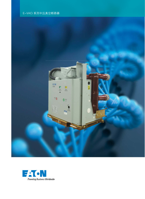
1250 2000 2500 3150
4000 (1) 40 40 100 100
AC 110/220 DC 110/220 65(31.5kA及以下),80(40kA)
≤15 分-0.3s-合分-180s-合分
分、合闸线圈技术参数
名称
额定工作电压(V) 合闸线圈额定工作电流(A) 分闸线圈额定工作电流(A) 正常工作电压范围
E-VACi 系列中压真空断路器
汽车
宇航 卡车
液压
电气
1
E-VACi系列中压真空断路器 2011年9月
遍布全球的电力业务
伊顿公司针对当今世界瞬息万变的需求,为成千上万种 产品提供了确实可行的电力解决方案。 我们服务全球用户,为他们的建筑,飞机,卡车,汽车, 机械及整个企业的发展提供电力支持及管理。我们的理 念就是减少资源的消耗。
分闸时间
ms
合闸时间
机械寿命
次
额定电流开断次数
额定短路电流开断次数
次
动、静触头允许磨损累计厚度
mm
额定合闸操作电压
V
额定分闸操作电压
储能电机额定电压
V
储能电机额定功率
W
储能时间
s
额定操作顺序
注:(1)4000A需要强制风冷。
630 1250
25 25 63 63
数值 12 42(相对地,相间) 48(断口) 75(相对地,相间) 85(断口) 50 630 1250 1600 31.5 31.5 80 80 2000 20~50 35~70 30000, (40kA为20000次) 30000, (40kA为20000次) E2(274) 3 AC 110/220 DC 110/220
Eaton 自动转换开关产品介绍说明书
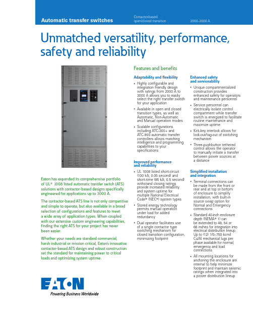
Unmatched versatility, performance, safety and reliabilityEaton has expanded its comprehensive portfolio of UL ா 1008 listed automatic transfer switch (ATS) solutions with contactor-based designs specifically engineered for applications up to 3000 A.The contactor-based ATS line is not only competitive and simple to operate, but also available in a broad selection of configurations and features to meet a wide array of application types. When coupled with our extensive custom engineering capabilities, finding the right ATS for your project has never been easier.Whether your needs are standard commercial,harsh industrial or mission critical, Eaton’s innovative contactor-based ATS design and robust construction set the standard for maintaining power to criticalloads and optimizing system uptime.Features and benefitsAdaptability and fl exibility•Highly configurable and integration friendly design with ratings from 2000 A to 3000 A allows you to easily select the right transfer switch for your application•Available in open and closed transition types, as well as Automatic, Non-Automatic and Manual operation modes •Scalable configurations including ATC-300+ and ATC-900 automatic transfer controllers allows matching intelligence and programming capabilities to your specificationsImproved performance and reliability•UL 1008 listed short-circuit (100 kA; 0.05 second) and short-time (85 kA; 0.5 second) withstand closing ratings provide increased reliability and system uptime for multiple National Electrical Code ா (NEC ா) system types •Stored energy technology permits manual operation under load for added redundancy•Dual operator facilitates use of a single contactor type switching mechanism forclosed transition configuration, minimizing footprintEnhanced safety and serviceability•Unique compartmentalized construction providesenhanced safety for operators and maintenance personnel •Service personnel can electrically isolate control compartment while transfer switch is energized to facilitate routine maintenance and maximize uptime•Kirk-key interlock allows for lock-out/tag-out of switching mechanism•Three-pushbutton tethered control allows the operator to manually initiate a transfer between power sources at a distanceSimplifi ed installation and integration•Terminal connections can be made from the front or rear and at top or bottom of enclosure to simplify installation, with built-in source swap option for Normal and Emergency connections•Standard 40-inch enclosure depth (NEMA ா 1) can be extended to 48, 54 or 66 inches for integration into electrical distribution lineup. Up to (12) 1/0–750 kcmil Cu/Al mechanical lugs per phase available for normal, emergency and load connections•All mounting locations for anchoring the enclosure are internal to help minimizefootprint and maintain seismic ratings when integrated into a power distribution lineupDesign featuresInnovativecompartmentalized design Eaton’s contactor-based ATS solutions are engineered for enhanced safety and uptime, with the front door of the ATS forming an isolatedcompartment that houses the automatic controller, control power transformer assembly, wire harnesses, relay logic, manual pushbutton controls, manual charging handle,terminal blocks and a variety of optional features to include a 2-position maintenance isolation switch (MIS).Upon opening the front door, service personnel can turn the MIS and electrically isolate the control compartment, while the transfer switch is energized. This innovativedesign enhances safety in the working environment when performing inspection or routine maintenance. Multiple operation modes and transition typesOperation is possible in three different modes: Automatic, Non-Automatic and Manual. In Automatic mode, a transfer is electrically initiated and operated via the controller.In Non-Automatic mode, a transfer is manually initiated and electrically operated using a door-mounted selector switch or via an optional tetheredremote control, which connects via a standard Ethernet cable. In Manual mode, a transfer is manually initiated and operated using integrally mountedpushbuttons located within an isolated compartment directly behind the front door.Further, the ATS can beconfigured as open or closed transition type. The opentransition type allows the user to select in-phase or delayed transition via programmable set points. The closed transition type can be configured to default to open transition if source synchronization doesn’t occur before a programmable delay timer expires.Tethered remote controlIntelligent ATS control Eaton’s new ATC-900 controller brings ease of use, adaptability, supervisory and programming capabilities to mission-critical applications. The 4.3-inch color TFT display provides simple arrow keys for quick screen navigation and easy viewing of event logs as well as recorded time-stamped events. Field configuration of programmable I/O allows user adaptability to special requirements.Multi-tap voltage selector Allows the transfer switch to be easily field configured for operation at different system voltages via a single quick-connect plug. Available system voltage group offerings include 208/240/480 Vac,220/380/415 Vac and 600 Vac.Multi-tap control power transformerContactor switching mechanismRobust double-throw switch construction includes dual operator and two-step stored energy technology. The operators can be charged electrically via motor or manually via handle. Once charged, stored energy allows for a complete transfer and re-transfer sequence to be performed. Manual controls and indication are integral to the design and many switching mechanism components are field replaceable. Selective coordinationTransfer switches can be configured with an optional UL 1008 listed short-time withstand closing rating of85 kA (0.5 seconds) that is ideal for emergency, legally required, critical operations data systems, and critical operations power systems requiring selectivecoordination per the NEC.Manual charginghandleManual operation controlsIsolated control compartmentATC-900automatic controllerMaintenanceisolation switchKirk-key interlockMulti-tapvoltageselectorLogic panel2EATON Automatic transfer switchesProduct selectionCatalog numbering system ATechnical specificationsDimensions and weightsNEMA 1NEMA 3R (controller and device panels mounted on inner door)A Dimension in inches (mm) and weight in lb (kg). Data is approximate and subject to change. Please reference product outline drawing(s) for latest information.B Standard depth extensions are available for integration into electrical distribution equipment line-up. Please contact your local Eaton sales representative for more details.Terminal information for external power conductorsA Standard mechanical lugs are UL listed, solderless screw-type Cu/Al. Number of conductors and size range shown is per pole.B Two-hole compression lug or bus provisions available upon request. Please contact your local Eaton sales representative for more details.C Only applies to wye system configuration with solid neutral. For four-pole, switched neutral configurations, the number and size of conductors supported will mimic Normal, Emergency and Loadinformation shown.A Some catalog number combinations may not be available. Please contact your local Eaton sales representative with any product configuration questions.B Non-automatic (open transition) type does not support open-inphase transition.3EATON Automatic transfer switchesEaton is a registered trademark.All other trademarks are property of their respective owners.Eaton1000 Eaton Boulevard Cleveland, OH 44122United States © 2016 EatonAll Rights Reserved Printed in USAPublication No. PA140009EN / Z18110April 2016Technical specificationsUL 1008 listed withstand closing ratingsATC-300+ and ATC-900 controller featuresA Modbus TCP/IP option requires use of Modbus RTU port.To learn more, contact your local sales representative or visit/atsCustom order engineeringIn many cases, standard product can be custom order engineered to meet your application needs. For additional information, please contact your local Eaton sales representative.Follow us on social media to get thelatest product and support information.。
E-VAC系列中压真空断路器

E-VAC 系列中压真空断路器伊顿电气的E-VAC 系列真空断路器融合了伊顿电气真空技术的卓越性能,集中体现了伊顿电气数十年配电系统方面丰富的设计和制造经验,具有可靠性高,操作方便,维护简单等特点,为中国用户提供了高性价比的产品。
符合IEC 、GB 、DL 等标准的规定 E-VAC 配用伊顿电气新一代的真空灭弧室,更适合电力系统的技术和运行条件 理想的触头材料和形状,保证小的截流值和稳定的接触电阻 零部件少,结构紧凑合理,确保操作更可靠、更安全 可理想的切合电阻、感性和容性负荷 在二次插头、底盘车、动触头以及接地方式等各方面的设计符合中国用户习惯,与国内主流中压开关柜KYN28柜型完全兼容产品使用条件周围空气温度不超过40℃,且在 24h 内测得的平均值不超过35℃。
最低周围空气温度为-15℃ 阳光辐射的影响可以忽略 周围空气没有明显的受到尘埃、烟、腐蚀性或可燃性气体、蒸汽或盐雾的污染 地震烈度不超过8度在二次系统中感应的电磁干扰的幅值不超过1.6kV技术特点E-VAC 采用成熟的弹簧操作机构,性能稳定、可靠,寿命长,操作简单,优秀的防腐蚀能力,寿命期内只需极少维护 E-VAC 采用了立式环氧绝缘筒可防御严酷环境的影响,使E-VAC 断路器适用于各种场合。
独特的触头材料和一次梅花触头应用,使E-VAC 断路器适用于中压系统的各种场合 按GB1984-2003中延长的电寿命E2级、延长的机械寿命M2级及容性电流开合具有非常低的重击穿概率C2级型式试验 外形尺寸和配柜联锁方式与国内主流中压开关柜KYN28柜完全兼容,通用性高,大大降低设计费用 产品装配采用工装保证尺寸的一致性,所有产品在出厂前均进行过标准柜的推柜试验,保证了产品的可互换性和通用性 所有产品出厂前经过数百次机械操作磨合试验,确保了产品性能处于最稳定的阶段 采用先进的进口测试设备,真实记录每一台产品的空载机械特性,并向用户提供这些特性曲线,确保产品质量的可靠性湿度条件应用领域在24h内测得的相对湿度平均值不超过95%在24h内测得的水蒸气压力平均值不超过2.2kPa月相对湿度平均值不超过90%月水蒸气压力平均值不超过1.8kPa主要规格与技术参数项目 化工工业石油工业管道工业海上开采造船工业造纸工业露天煤矿单位数值变电所,变电站水泥工业汽车工业发电厂纺织及食品工业冶金工业额定电压kV 12额定短时工频耐受电压(1 min)kV 42(相对地,相间) 48(断口)额定雷电冲击耐受电压(峰值)kV 75(相对地,相间) 85(断口)额定频率Hz 50额定电流 A 630 630 1250 1250 1600 1250 16001250 1600 2000 2000 2500 2000 25003150 4000(1) 3150 4000(1)额定短路开断电流kA 25 31.5 40 50额定短时耐受电流(4s)kA 25 31.5 40 50额定峰值耐受电流kA 63 80 100(2) 125额定短路关合电流kA63 80 100(2) 125机械寿命次20000, (50kA为10000次)额定电流开断次数次20000, (50kA为10000次)额定短路电流开断次数次E2(274)注:(1) 4000A需要强制风冷。
- 1、下载文档前请自行甄别文档内容的完整性,平台不提供额外的编辑、内容补充、找答案等附加服务。
- 2、"仅部分预览"的文档,不可在线预览部分如存在完整性等问题,可反馈申请退款(可完整预览的文档不适用该条件!)。
- 3、如文档侵犯您的权益,请联系客服反馈,我们会尽快为您处理(人工客服工作时间:9:00-18:30)。
kV
12
Hz
50
kV
42(相对地,相间)
48(断口)
kV
75(相对地,相间)
A
1600/2000
kA
31.5
85(断口)
1600/2000/ 2500/3150/4000*
40
kA
80
100
%
50
kA
31.5
40
kA
80
100
O-0.3s-CO-180s-CO
μΩ
≤35(1600~2000A) ≤25(2500A以上)
伊顿是多样化的工业制造公司,2007年销售额达130亿美元。伊顿在液 压、工业服务、移动通讯、航空设备、供电、电能质量,配电和监控、汽车引 擎系统、空气动力系统、燃油发电控制、智能燃油驱动系统和汽车安全领域居 全球领先地位。伊顿员工达79000名,产品客户遍布150个国家。更多的信息请 访问。
作为伊顿公司的第一大业务部门,电气集团2007年的销售额达到48亿 美元,电气集团在电气控制、配电、工业控制和电能质量的制造和服务领域位 于全球领先地位,在设计、研发、制造和应用方面上给予用户提供最优质的服 务以及最先进的产品。通过一系列的收购和兼并计划,伊顿电气集团有以下成 功的著名品牌,如:Westinghouse®,Holec®,Cutler-Hammer®, Heinemann®和Powerware®,Moeller®,Phoenixtec®,同时伊顿电气集团继 承并发扬了这些著名公司的技术和工程经验。伊顿持续坚持这些著名品牌的 传统和发扬她们的独特优点,为中国乃至全世界的客户提供有效的解决方案 和服务。详细情况可以访问:。
E -VAC完全满足中国电力用户需要
E-VAC真空断路器采用伊顿电气大爬距绝缘真空灭 弧室并增大了绝缘件的爬距,有效地保证了截流值小于3A, 使开断性能更为稳定。
E -VAC用途多样化
采用了立式环氧绝缘罩可防御严酷环境的影响,使 E-VAC断路器适用于各种场合。
独特的触头材料和一次梅花动触头应用,使E-VAC 断路器适用于中压系统的各种场合。
E -VAC系列真空断路器二次控制接线图
说明: 1.图示为断路器处于试验位置、未储能,分闸状态; 2.当操作电源为直流时,虚线框中的极性应相同。
防跳继电器(可选)
JP1~JP取消)
S9: 辅助开关(当断路器在工作位置时切换) S8: 辅助开关(当断路器在试验位置时切换) S2: 辅助开关 S1: 辅助开关(合闸弹簧蓄能后切换) QF: 辅助开关(分合操作时切换)
6
7
E -VAC系列真空断路器选型表
E -VAC系列真空断路器参数
柜体宽度 (mm)
断路器相间距 (mm)
800
210
1000
275
*4000A需强制风冷
弹簧操动机构技术参数
分闸电源(V) 合闸电源(V) 储能电机电源(V)
额定短路开断电流(kA) 25 31.5 31.5 40
额定工作电流(A) □630 □1250
□ 2过流 □V □V □V □V □所需数量
□ 3过流
□
A
8
我们拥有全球最大的、一直处于世界领先水平的真 空灭弧室工厂,并且是全球唯一一家拥有大容量高压实验 室的真空灭弧室厂。
我们的制造能力和设计研发始终处在领先的位置。
真空灭弧室和机构具有最佳配合
由于伊顿电气拥有先进的现代化EBS生产管理和在 工业界甚至全世界公认的技术专家,E-VAC真空断路器 都配有为中国市场专门开发生产的大爬距真空灭弧室,与 E-VAC简单可靠的机构的完美组合,使得E-VAC真空断 路器不但在性能、安全及功能等方面保持世界一流的水平, 而且使爬电绝缘距离大大增加,进一步提高了伊顿真空断 路器的绝缘水平、安全性及可靠性,完全满足了中国客户 不同应用场合的需求。
可选附件
储能手柄
小车摇手柄
升车
弹簧操动机构参数
储能电机技术参数
名称 额定工作电压(V) 电动机额定输入功率(W) 正常工作电压范围 在额定工作电压下储能时间(s)
分、合闸线圈技术参数
名称 额定工作电压(V) 合闸线圈额定工作电流(A) 分闸线圈额定工作电流(A)
正常工作电压范围
AC,DC110
参数
AC,DC220
伊顿电气的E-VAC系列真空断路器融合了伊顿电气 真空技术的卓越性能,集中体现了伊顿电气数十年配电系 统方面丰富的设计和制造经验,具有可靠性高,操作方便, 维护简单等特点,为中国用户提供了高性价比的产品。
符合DL、GB、IEC等标准的规定 配用伊顿电气新一代的真空灭弧室,更适合电力系统 的技术和运行条件 理想的触头材料和形状,保证小的截流值和稳定的接 触电阻 零部件少,结构紧凑合理,确保操作更可靠、更安全 可理想的切合电阻、感性和容性负荷 紧凑的本地化设计使断路器与中国市场的主流柜型完 全兼容
65 85%~110%额定工作电压
≤15
AC,DC110
参数
AC,DC220
2.0
1.0
1.8
0.9
合闸:80%-110%额定工作电压
分闸:65%~120%额定工作电压,小于30%额定工作电压时不分闸
2
3
技术数据(相距210mm)
额定电压 额定频率 额定 1 min 工频耐受电压 额定雷电冲击电压 额定电流 额定短时耐受电流(4s) 额定峰值耐受电流 额定短路开断电流直流分量 额定短路开断电流 额定短路关合电流 额定短路操作顺序 每相导电回路电阻 触头开距 分闸反弹幅值 平均合闸速度 平均分闸速度 合闸时间 分闸时间 触头合闸弹跳时间 三相触头合,分不同期性 相间中心距离 动、静触头允许磨损厚度 机械寿命
产品型号
120 E - VAC R 40 / 3150
额定电流 额定短路分断电流 R代表固定式,无代 表抽出式 IEC/GB型断路器 E:经济型 电压等级
湿度条件如下:
在24h内测得的相对湿度平均值不超过95% 在24h内测得的水蒸气压力平均值不超过2.2kPa 月相对湿度平均值不超过90% 月水蒸气压力平均值不超过1.8kPa
中压供配电系统中控制与保护的最佳选择
断路器所配操作机构是性能优异的弹簧储能机构,采 用模块化设计,使机构主件分布更优化、机构更简单、 性能更稳定。整个机构由三个模块组成:储能、合闸、 分闸。这三个部分组装维护非常简单,而储能机构由 棘轮机构、摆动装置及合闸弹簧组成,机构紧凑、小 巧。操作机构通常都配有手动储能装置与电动储能装 置,可实现自动重合闸功能。 手动储能操作机构的断路器通常设有手动分合操作按 钮,断路器位置指示器及弹簧机构储能状态指示器, 开关操作次数计数器,分励脱扣器辅助开关,位置和 故障信号等装置。 电动储能操作机构的断路器:增设有储能电机,分励 脱扣器,防跳继电器,储能电机脱扣器的辅助开关。 还可以根据具体要求提供以下附件:欠压脱扣器、过 流继电器等。
伊顿电气有限公司 苏州工业园区苏虹西路193号 苏州工业园区苏虹中路306号 Tel: 0512-67163728 62585099 Fax: 0512-67169535 62585076 Postcode: 215021
Partner
版本号:EESZ-MV-E-VAC-0805 本公司保留对样本资料的解释权和修改权, 且毋须另行通知. 2008.05
应用领域
化工工业 变电所,变电站 石油工业 水泥工业 管道工业 汽车工业 海上开采 冶金工业 造船工业 纺织及食品工业 造纸工业 发电厂 露天煤矿
1
技术创造历史
伊顿电气作为世界第一个真空灭弧室的制造者、真 空技术的先驱,我们研究、开发和生产真空灭弧室已有 70多年的历史,积累了极为丰富的经验。西屋的名字已 经成为质量和可靠的同名词。
25~31.5 25~31.5
31.5 31.5~40
40
210 275 638 652 640 650 433 626 ø35 280 598 76 78 637 508 277 40 210 275 638 652 640 650 433 626 ø49 280 598 76 78 637 508 277 40 210 275 638 652 640 650 433 626 ø55 280 598 76 78 637 508 277 40 275 310 838 852 838 850 361 680 ø79 295 586 77 88 698 536 377 0 275 310 838 852 838 850 361 680 ø109 295 586 77 88 698 536 377 0
分闸回路
K0:
M:
梅花触头与静触头啮合尺寸
闭锁回路
合闸回路
过流脱扣(A相) 过流脱扣(C相) 过流脱扣(B相)
电机回路
额定电流
额定短路
配柜宽度 (A)
开断电流(kA) P
H
ABCD
E
F
G
J
K LMN
RS T
800 800 800 1000 1000
630 1250 1600 1600~2000 2500~4000
4
kV
12
Hz
50
kV
42(相对地,相间)
48(断口)
kV
75(相对地,相间)
85(断口)
A
630/1250
630/1250/1600
kA
25
31.5
kA
63
80
%
50
kA
25
kA
63
31.5 80
O - 0.3s - CO-180s-CO
μΩ
≤60(630A)
≤50(1250A)
≤35(1600A)
E -VAC真空断路器几乎无须相应的维护 和保养