印刷线操作软件
各种GERBER文件处理CAM软件简介
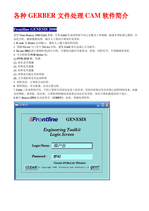
各种GERBER文件处理CAM软件简介Frontline GENESIS 2000采用Valor Genesis 2000 CAM系统,可将CAM作业流程依不同之层数及工料规格,做成多项标准之模块,自动化分析,编修数据处理,减少人工错误并增加作业效率。
1. D-code及Gerber自动输入,避免人工输入错误的风险。
2. 原稿Net list与工作片Net list比较,避免CAM设计造成之人为疏失。
3. On line DRC(设计规则检查)设计全程,可避免功能信号被更动,线宽、间距信号,不因编修而变更。
4. 可分析检查PCB Gerber如:(1) PWR GND断、短路(2) 钻孔是否遗漏(3) 焊垫是否遗漏(4) 防焊是否遗漏(5) 焊垫是否超出至防焊面(6) 文字或防焊是否沾到焊垫5. 制程误差,计算机自动补偿。
6. 特性阻抗,多层搭叠,自动计算分析。
7. CAM工作流程程序化,不因工程师不同而有品质上的差异。
资料在转换后传至外围之制程网络设备,如激光绘图机、成型机、钻孔机、计算机网络测试设备和自动比对光学机,皆在计算机数值控制下进行。
8.编写Genesis DFM自动化程式(SCRIPTS)高效、快捷处理资料。
ParCAM的功能ParCAM使用在Win95/Win98/Win2000/WinXP等操作系统中,对机器的配置要求很低,不需要像Genesis2000或UCAM等软件那样,必需要Win2000系统下才能运行,ParCAM最低的系统要求只是Windows95即可运行。
A: 介绍ParCAM的INPUT:可自动辨识的Aperture格式已高达559种。
可自动读入的图形格式:Standard Gerber formatRS-274D、RS-274XIPC-D-350、IPC-D-356、IPC-D-356AGDSIIMDADPF ( BARCO )IMARKDXF、HPGLOptrotech BackupODB++MENTOR Neutral fileGenCAM( 此为IPC推广之新世代CAM资料格式)Drill Tape:EXCELLON 1 & 2、HITACHI 1 & 2、TRUDRIL、Posalux、Sieb & Meyer特点:ParCAM 在读入资料时,系统可自行作资料格式之分类,操作者不必多一道手续,事前了解资料格式之内容及预作分类。
利用Protel设计制作专业级印刷电路板
上 ( 一 般文 印部提供转 印纸 , 如没 有可 到 网上 购买 或用
不 干 胶 纸 衬 底 , 即浅 黄 色 的表 面 光 滑 的那 一 面 ) 。
2 . 把对 贴 好 的敷铜 板 和转 印制放 在 一 平 坦 处 , 将 温 度 高达 2 0 0 ~C 以 上 的熨斗置 于 其上 片刻 。 自然 冷却后 揭
掉 转 印纸 。
3 .将 敷铜板 置 于 三 氯化铁 溶液 中 ,2 0 分钟后 取 出 即
可 。 为加快腐蚀速度可将溶液加热或搅动溶液 。 ( 注意
应用耐腐蚀容器 )其他与实验室制作方法相 同。
四 、结论
采用 以上 技术制作 的印刷板 精度高 ( 理 论 上 可达
到激光 打 印机 的分 辨率 ) 、 速 度快 、 成本 低 , 解 决 了设 计
吸附的墨粉受热融化 。 由于转 印纸 表面 异 常光滑 , 当温度 达到 2 0 0 ~C左 右时 , 它对墨 粉 的吸附力急剧下 降 , 使融化
的墨 粉完全 吸附到敷铜板上 , 待敷铜板 冷却后 ,就在其表
面形成 了牢 固的印刷线路 图 。 由于 墨粉对 三 氯化铁具有
良好的抗腐蚀性 所 , 以此 图形就是可靠的保护层 。 送 入 腐
2 .信号线宽度约
O .
5
m
m
,地 线 、 电源线应略宽 。
3 . 主要 信号线尽量 汇 聚于 板 中间 ,最 好 置 于地 线所
形 成 的闭环 内 ;尽量 避 免 长 距 离平 行 布线 ;信号 导 线 拐
角尽 量设 计成 圆形 、 圆弧 形 ,切忌 画 成直 角或锐角 。
4 .选用标准器件封装 。
不能物化为产 品 的问题
,为寻找差距
进一
、
eps线条操作流程
eps线条操作流程EPS(Encapsulated PostScript)是一种矢量图形格式,常用于印刷和出版领域。
EPS文件中包含了图形的矢量信息和文本信息,可以在不失真的情况下进行放大和缩小。
在印刷行业中,EPS文件通常用于制作标志、海报、名片等印刷品。
EPS线条操作是指在EPS文件中对线条进行编辑和处理的过程。
下面是EPS线条操作的流程:1. 打开EPS文件:首先,需要打开包含需要编辑的EPS文件。
可以使用Adobe Illustrator等专业的矢量图形编辑软件来打开EPS文件。
2. 选择线条工具:在编辑软件中,选择线条工具,可以是直线工具、曲线工具或者画笔工具,根据需要选择合适的工具。
3. 绘制线条:使用选定的线条工具,在EPS文件中绘制需要的线条。
可以根据设计要求绘制直线、曲线、圆弧等不同形状的线条。
4. 编辑线条:对绘制好的线条进行编辑,可以调整线条的粗细、颜色、样式等属性。
也可以对线条进行变形、旋转、复制等操作。
5. 添加文本:在需要的位置添加文本信息,可以是标题、标注、说明等内容。
调整文本的字体、大小、颜色等属性,使其与线条相匹配。
6. 组合线条和文本:将线条和文本组合在一起,形成完整的图形。
可以使用组合工具将线条和文本进行组合,方便后续的操作。
7. 导出文件:编辑完成后,将EPS文件导出为其他格式,如PDF、JPG等。
可以根据需要选择不同的导出格式,以便于后续的使用和分享。
总的来说,EPS线条操作流程包括打开文件、绘制线条、编辑线条、添加文本、组合图形和导出文件等步骤。
通过对EPS文件中的线条进行操作,可以实现各种设计要求,为印刷和出版领域提供高质量的图形素材。
GCCAM软件操作指南(80页精本大全)
第一部分GC-CAM简介GC-CAM是介于CAD与PCB制造之间的桥梁,可以对PCB制造所需数据,如线路、防焊、文字(GERBER)、加工程式(NC、ROUTER)等进行有效的处理,对初学者来说,不失为PCB CAM制作的利器。
1.1 导入和输出格式GC-CAM可以导入的数据类型:Gerber(RS-274-D及RS-274-X)、Drill(钻孔资料)、Rout (铣床资料)、HPGL、Emma/Quest等,可以根据自定义类型(GC-CAM自身提供的PDF编写格式)进行导入。
GC-CAM可以根据用户定义(PDF格式)输出所需类型,其可直接输出的格式有:DPF、IPC-D-350、FIRE、RS-274-X、EIE、SECMA、Escher-Grad、356(IPC-D-356)、HoloFlash等,也可绘图输出HPGL、Postscript、DMPL、Linotronic、AUTOCAD DXF等格式文件。
随着版本的更新,GC-CAM所能导入、输出的格式更多,兼容性更强。
1.2 GC-CAM功能及特点GC-CAM软件在Windows 下可以利用菜单、鼠标、键盘协同操作,方便灵活,可以实现多种功能,一些常用功能简列如下:⏹自动进行线路(TRACE)、焊盘(PAD)线宽及线距,单边铜,重叠,未终结的线路进行检查。
⏹孔自动校正,层对齐,Vent图案建立,铜箔面积计算。
⏹自动图面居中(PANEL方式下)。
⏹Coupons图案定义、插入。
⏹钻孔及铣床程式优化建立输出。
⏹检查输出各种格式,幷可自定义输出比例及各种参数。
⏹图层设置、拷贝、合幷,窗口多样化。
⏹多层资料编辑(拷贝、删除、移动、旋转、镜像、填充、隔离、自定义PAD图形替代等)、还原、文字建立、自动切割、层属性设置(正、负、相减图层)等等,以达到WYSIWYG (所见即所得)的效果。
⏹图层、D码、孔径表支持99层,多种颜色,支持多种形状的D码。
印刷软件中常用的快捷键和操作技巧
印刷软件中常用的快捷键和操作技巧在现代印刷业中,印刷软件的使用已经成为了必不可少的工具。
印刷软件的功能强大,但是如果只是简单地使用一些基本的功能,那么很难发挥其最大的效益。
本文将介绍一些印刷软件中常用的快捷键和操作技巧,帮助读者更加高效地使用印刷软件。
一、常用快捷键1. Ctrl + N:新建一个文件。
在印刷软件中,新建一个文件是最基本的操作之一。
通过使用这个快捷键,可以快速地新建一个文件,方便进行后续的操作。
2. Ctrl + O:打开一个已有的文件。
如果要编辑一个已有的文件,可以使用这个快捷键快速地打开它,而不需要通过菜单栏的“文件”选项来进行操作。
3. Ctrl + S:保存当前文件。
在编辑文件的过程中,经常需要保存文件以防止数据的丢失。
通过使用这个快捷键,可以快速地保存当前文件。
4. Ctrl + Z:撤销上一步操作。
在编辑文件的过程中,有时候会不小心进行了一些错误的操作。
通过使用这个快捷键,可以快速地撤销上一步操作,恢复到之前的状态。
5. Ctrl + C:复制选中的内容。
在编辑文件的过程中,有时候需要复制一些内容以供后续使用。
通过使用这个快捷键,可以快速地复制选中的内容。
6. Ctrl + V:粘贴复制的内容。
在编辑文件的过程中,有时候需要将之前复制的内容粘贴到其他地方。
通过使用这个快捷键,可以快速地粘贴复制的内容。
7. Ctrl + X:剪切选中的内容。
在编辑文件的过程中,有时候需要将选中的内容移动到其他地方。
通过使用这个快捷键,可以快速地剪切选中的内容。
8. Ctrl + A:全选当前文件中的内容。
在编辑文件的过程中,有时候需要对整个文件进行操作。
通过使用这个快捷键,可以快速地全选当前文件中的内容。
二、常用操作技巧1. 使用图层:印刷软件中的图层功能非常强大,可以将不同的元素分别放置在不同的图层中,方便后续的编辑和调整。
在设计文件时,可以根据需要创建多个图层,并将不同的元素放置在不同的图层中,以便于后续的操作。
常用电子CAD软件
常用电子CAD软件电子设计CAD软件及介绍电子设计工具层出不穷,目前进入我国并具有广泛影响的EDA软件有:ultiumderigner、EWB、PSPICE、OrCAD、PCAD、Protel、Viewlogic、Mentor、Graphic、Synopy、LSIlogic、Cadence、MicroSim、Protel、OrCAD、Viewlogic、PowerPCB、CadencePS、MentorGraphice的E某peditionPC、ZukenCadStar、Winboard/Windraft/Ive某-SPIC、PCBStudio、TANGO等等。
这些工具都有较强的功能,一般可用于几个方面,例如很多软件都可以进行电路设计与仿真,同时以可以进行PCB自动布局布线,可输出多种网表文件与第三方软件接口。
工具较多,无法一一介绍,下面按主要功能或主要应用场合,在我国影响较大,使用范围较广,功能强大的CAD软件进行分类介绍,按功能可分为电路设计与仿真工具、PCB设计软件、IC设计软件。
电路设计及仿真软件:主要软件有:SPICE/PSPICE、EWB、Matlab、SytemView、MMICAD。
1)SPICE(SimulationProgramwithIntegratedCircuitEmphai)是由美国加州大学推出的电路分析仿真软件,是20世纪80年代世界上应用最广的电路设计软件,1998年被定为美国国家标准。
1984年,美国MicroSim公司推出了基于SPICE的微机版PSPICE(Peronal—SPICE)。
现在用得较多的是PSPICE6.2,可以说在同类产品中,它是功能最为强大的模拟和数字电路混合仿真EDA软件,在国内普遍使用。
最新推出了PSPICE9.1版本。
它可以进行各种各样的电路仿真、激励建立、温度与噪声分析、模拟控制、波形输出、数据输出、并在同一窗口内同时显示模拟与数字的仿真结果。
常用版式设计软件

常用版式设计软件●文字处理与编辑软件←文字处理与编辑软件主要包括Microsoft Word、Microsoft Excel、AppleWorks等。
这些软件有强大的文字处理能力,并且有一些基本的排版功能,主要用于办公室中做一般的文字处理工作。
●商务排版软件←商务排版软件主要包括Adobe PageMaker、FreeHand和QuarkXpress等。
这类软件具备文字处理、简单绘图和普通排版的功能。
可以用这些软件制作商务简报、宣传手册以及简单的版式设计。
在过去很长的一段时间里,有这些排版软件就能够满足广大用户的基本需求。
●专业排版软件:←InDesign便是专业排版软件的代名词。
因为这一软件符合各类专业印刷出版的要求和标准。
并综合了PageMaker和QuarkXPress软件的优势,能够处理如杂志、报刊版面等复杂的设计,可以制作专业品质的精美印刷品。
随着印刷市场对于印刷物品质的更高要求,对于从事专业出版工作的用户来说,InDesign软件是首选。
InDesign软件介绍InDesign软件是Adobe公司研发的一款定位于专业排版领域的设计软件,是面向公司专业出版方案的新平台。
适用于制作报纸、杂志、宣传册、书籍、平面广告和电子杂志的图形图像编辑及排版。
将已处理好的文字、图片和图形等可视化信息元素,在版面布局上调整位置、大小,使版面布局条理化的过程。
按照稿本把文字、图版等排在一起拼成书版的版子,以供印刷。
桌面出版系统的工艺流程Indesign的工作流程InDesign为用户提供了正常、预览、出血和辅助信息区四种模式,并具有独自的特点。
正常模式:它能够在标准窗口中显示版面及所有可见网格、参考线、非打印对象、空白粘贴板等;预览模式,制作完成后,可进行效果的预览;出血模式:可以查看页面内容是否完整,以防在后期制作时将内容裁剪辅助信息区模式:显示为像剪切标志和用于最后输出的颜色分色名称等信息保留的空间。
ProtelDXP教程及PCB常识

2、PCB设计后的仿真分析阶段
在PCB的布局、布线过程中,PCB设计人 员需要对产品的信号完整性、电源完整性、 电磁兼容性、产品散热情况作出评估(即软 件仿真测试)。若评估的结果不能满足产品 的性能要求,则需要修改PCB图、甚至原理 设计,这样可以降低因设计不当而导致产品 失败的风险,在PCB制作前解决一切可能发 生的设计问题,尽可能达到一次设计成功的 目的。该流程的引入,使得产品设计一次成 功成为了现实
EDA简介
1、
Electronic Design Automation(EDA)---电子设计自动化。内容丰富、软 件较多。Protel是其中之一,其发展过程如下:TangoProtel for DosProtel for Windows1.0/1.5 Protel3.16 Protel98 Protel99 Protel99se Protel DXP 2、EDA主要内容: SCH:原理图设计 PCB:印刷电路板设计 PLD:可编程逻辑器件设计 SIM;电路仿真 SI: 信号完整性分析 3、学习目的: EDA是使用性极强的一门操作技能课,掌握操作技能;掌握Protel的基本操作技 巧学会设计SCH和PCB,了解SIM。
利用EDA工具,电子设计师可以从概念、 算法、协议等开始设计电子系统,大量工作 可以通过计算机完成,并可以将电子产品从 电路设计、性能分析到设计出PCB版图的整 个过程的计算机上自动处理完成。 现在对EDA的概念范畴用得很宽。包括在 机械、电子、通信、航空航天、化工、矿产、 生物、医学、军事等各个领域,都有EDA的 应用。目前EDA技术已在各大公司、企事业 单位和科研教学部门广泛使用。例如在飞机 制造过程中,从设计、性能测试及特性分析 直到飞行模拟,都可能涉及到EDA技术。本 书所指的EDA技术,主要针对电子电路设计、 PCB设计。
smt离线编程软件介绍

smt离线编程软件介绍iGSTforSMT smt坐标采集离线编程软件,是SST通用smt坐标采集软件的新一代产品,它包含了SST的所有功能并增加了GERBER文件坐标识别的功能,它是离线编程的辅助工具,GSTforSMT涵盖SMT生产所需坐标的三个主要的获取途径,1 GERBER文件自动识别,2 PCB的扫描,3 XY坐标的导入及BOM表的合并,它是一个三合一的工具软件,它们可以极大的加快SMT贴片程序编程的速度,并缩短生产线的停线时间.GSTforSMT smt坐标采集离线编程软件的作用就是利用客户提供的GERBER文件或PCB和BOM资料,通过自动计算分析获得SMT贴装的精确坐标,并自动分析丝印图层计算出贴装位置的丝印字符,还可以导入文本或EXCEL文件的BOM资料,最后分析组合后输出坐标文本文件给贴片机的编程软件,工程师在离线状态下用SMT编程软件能够完成元件坐标数据、元件数据库的编辑、生产线贴片料的分配,Feeder站位的排列、料站表的打印以及应的作业指导书。
GSTforSMT 通用smt 坐标采集软件充分吸取SST软件成功经验并,经过多个smt企业的使用,证明该软件对于smt企业的作用是非常有效和方便的。
它操作简单而且专一并且经过千锤百炼。
支持的机器,目前可以支持所有可以导入TXT坐标的SMT贴片机,有三星全系列,环球全系列,FUJI全系列,JUKI全系列,松下全系列等,直接生成贴片机程序,目前可以直接生成三星CP45的PCB程序和FUJI FLEXA 的JOB程序文件,支持自动调用元件数据库GSTforSMT smt坐标采集软件特点GERBER文件识别精确,从PCB的生产文件GERBER中直接计算出元件贴装坐标, 使用全新的算法,在字符识别上达到极高的识别率,GSTforSMT能识别出gerber 文件中95%以上的字符操作简便,只需按四个功能键就可以找出坐标和对应的丝印字符PCB扫描,支持PCB精细旋转校正和XY轴的变形校正,用PCB扫描也可以达到极高的精度,使用最新的图形技术,可实现PCB图片的无级旋转和无级缩放bom资料和cad数据的导入,支持各种错误的校验,并使用不同的颜色区分数据全中文全中文界面,不懂英文也可以操作了,再也不用拼命看英文的菜单了支持TXT文本格式和EXCEL格式的BOM资料,可直接导入合并到坐标数据中支持多种格式的坐标数据输出直接生成贴片机程序,目前可以直接生成三星CP45的PCB程序和FUJI FLEXA 的JOB程序文件,支持自动调用元件数据库,没有元件数据的新元件可以调用已经存在的元件数据生成,400个点的程式,20分钟就可以上机台已经不是梦想,GSTforSMT帮你把SMT编程中最耗时的三个阶段,坐标输入阶段,bom资料输入阶段,元件数据库制作阶段,所消耗的时间缩短到最小,极大的提高了生产效率GSTforSMT特点详解1 精确GSTforSMT从PCB的生产文件GERBER中直接计算出元件贴装坐标,所得到坐标是和设计坐标是一致的,不会因为人为的因素或其他因素而发生偏差,能达到极高的准确度,如果贴片机的进度足够准确,可以说基本不用校正就可以直接使用GSTforSMT软件产生的坐标进行生产,即使是使用PCB扫描方式,也可以通过自动旋转校正和XY轴校正来获取高精度的坐标数据2 字符搜索准确GSTforSMT 在字符搜索上采用全新的算法,在字符识别上达到极高的识别率,GSTforSMT能识别出gerber文件中95%以上的字符,如果GERBER文件使用的是常用字体,而不是形状怪异的字体,而且两个元件的焊盘间距超过一个字符宽度以上,GSTforSMT软件通常可以100%的正确搜索出所有字符并且坐标与字符的对应关系是正确的,当PCB很复杂,焊盘非常密,连字符都无法印下时,字符印刷在比较远的地方,GSTforSMT仍然可以搜索出所有字符,在字符与焊盘的对应关系上也可以达到很高的正确率,并且提供良好的操作方式,让用户直接点取正确地字符就可以修正错误,而不用手工输入,可以极大的加快获取坐标和贴装位置编号的速度.3 效率高GSTforSMT能有效的缩短SMT生产线换线时间。
线路板设计软件

线路板设计软件一、Protel 99se 线路板设计软件Protel99组成:1、原理图设计系统原理图设计系统是用于原理图设计的Advanced Schematic系统。
这部分包括用于设计原理图的原理图编辑器Sch以及用于修改、生成零件的零件库编辑器SchLib。
2、印刷电路板设计系统印刷电路板设计系统是用于电路板设计的Advanced PCB。
这部分包括用于设计电路板的电路板编辑器PCB以及用于修改、生成零件封装的零件封装编辑器PCBLib。
3、信号模拟仿真系统信号模拟仿真系统是用于原理图上进行信号模拟仿真的SPICE 3f5系统。
4、可编程逻辑设计系统可编程逻辑设计系统是基于CUPL的集成于原理图设计系统的PLD设计系统。
5、Protel99内置编辑器这部分包括用于显示、编辑文本的文本编辑器Text和用于显示、编辑电子表格的电子表格编辑器Spread。
Protel99主要特色:Protel99是基于Win95/Win NT/Win98/Win2000的纯32位电路设计制版系统。
Protel99提供了一个集成的设计环境,包括了原理图设计和PCB布线工具,集成的设计文档管理,支持通过网络进行工作组协同设计功能。
Protel99的主要特性如下:(1) Protel99系统针对Windows NT4/9X作了纯32位代码优化,使得Protel99设计系统运行稳定而且高效。
(2) SmartTool(智能工具)技术将所有的设计工具集成在单一的设计环境中。
(3) SmartDoc(智能文档)技术将所有的设计数据文件储存在单一的设计数据库中,用设计管理器来统一管理。
设计数据库以.ddb为后缀方式,在设计管理器中统一管理。
使用设计管理器统一管理的文档是在Protel99中新提出来的,以前版本中没有。
(4) SmartTeam(智能工作组)技术能让多个设计者通过网络安全地对同一设计进行单独设计,再通过工作组管理功能将各个部分集成到设计管理器中。
印能捷操作流程

精练文件 RGB 转四色选项
精练文件 折页选项
精练文件 专色转四色选项
创建拼版方案
做完前面的工作后,就可以拼大版了
这里输入版方案名称,一般为自反, 天地反,单面,内页,封面,骑马 订,锁线胶装,无线胶装等,根据 实际情况自定
创建拼版方案
这里输入该拼版方案的总 P 数
这 里 会 自 动 跳 转 到 preps 软 件,到 preps 中加入相应模版
讲解:人家天堂 QQ: 329186959 电话 :13588747199
登录
这里是客户端主界面,在这里点加 号找到文件夹下面的文件,双击打 开
这里是作业主界面,有三种状态 显示,分别为页面,印张,分色, 点击相应的图标就可显示相应的 状态。以下讲三种状太的区别
登录
界面显示
2. 界面显示
这里是页面状 态,可以看到文 件的页面的顺 序,分配页面(后 面详解)
创建拼版方案
在印能捷中工作完成后会跳转 到这里,贴上相应的模版
创建拼版方案 模版贴好后,打印到印能捷中
创建拼版方案 模版打印到印能捷中后,按顺序把文件拖到相应的页面
做完前面的工作后,切换到印张状态,选中 需要输出的印张,执行相应的输出选项。
输出处理
输出处理
在某些情况下只需输出某一颜色,在分色状态 下选中该颜色,执行相应的输出选项。
技巧: 如需添加多个文件可以按住 Ctrl 或 Shift 键,这 两个键该怎么用就不多说了。如需添加某一文 件夹中的所有文件,点全部添加就行了。
输入文件
文件添加成功以后在输入文件的下方可以 看到输入的文件名称及格式,文件大小等 信息
P-touch P700软件使用说明书
重要事项
本说明书的内容及本产品的规格如有变更,恕不另行通知。 Brother 公司保留在不另行通知的情况下,对其中所包含的规格和材料进行更改的权利,同时由于信任所引
用的材料所造成的损害 (包括结果性损害) ,包括但不限于印刷上的错误和其他与此出版物相关的错误 Brother 公司将不承担责任。 本说明书中的屏幕图像可能会因您的计算机操作系统和产品型号而有所不同。 在使用 P-touch 之前,请仔细阅读 P-touch 随附的所有文档,以获取安全和正确操作的相关信息。
6 如何更新 P-touch 软件
24
更新 P-touch Editor..................................................................................................................................24 更新固件 /P-touch Editor Lite...................................................................................................................26
brother公司保留在不另行通知的情况下对其中所包含的规格和材料进行更改的权利同时由于信任所引用的材料所造成的损害包括结果性损害包括但不限于印刷上的错误和其他与此出版物相关的错误brother公司将不承担责任
软件使用说明书
P-touch P700
本说明书的内容及本产品的规格如有变更,恕不另行通知。 Brother 公 司保留在不另行通知的情况下,对其中所包含的规格和材料进行更改的 权利,同时由于信任所引用的材料所造成的损害 (包括结果性损害), 包括但不限于印刷上的错误和其他与此出版物相关的错误 Brother 公司 将 不 承 担 责 任。本 说 明 书 中 的 屏 幕 图 像 可 能 会 因 您 的 操 作 系 统 或 P-touch 而有所不同。
用PROTEUS设计制作印刷电路板

用PROTEUS设计制作印刷电路板摘要:这份论文介绍了如何使用PROTEUS软件设计和制作印刷电路板(PCB),包括电路设计、尺寸布局、线路距离等相关内容。
通过PROTEUS软件,可以轻松生成PCB原理图,并进行切片的导出,最终生成PCB制造所需的Gerber文件。
本文将详细介绍PROTEUS软件在PCB设计和制造过程中的具体操作步骤。
关键词:PROTEUS,印刷电路板,设计,制作,Gerber文件正文:一、引言PCB(Printed Circuit Board)电路板是电子产品中非常重要的一个组成部分,其作用相当于各种元器件的桥梁,它将每个元器件之间的连接点通过导线和电路板来进行连接,使电路得以工作。
PCB通常由纸片和玻璃纤维布层嵌合而成。
为了方便大规模制造和维修,现在的电路板都采用机器制造加工,即通过将电路确定下来并进行自动化加工的方式来生产。
在这个过程中,PROTEUS软件则具有至关重要的作用。
下面,本文将详细介绍如何使用PROTEUS软件进行PCB的设计和制造过程。
二、PROTEUS软件介绍PROTEUS是一款由英国Labcenter开发的软件,主要用于虚拟设计和仿真电路。
利用该软件,电子工程师可以在一个完整的虚拟环境中完成电路设计、仿真和制造等一系列工作。
其中,PCB设计就是PROTEUS的其中之一重要的功能。
三、PCB设计步骤1. 建立 PCB 原理图首先,我们需要在PROTEUS中创建一个新的PCB工程。
为此,我们可以在“File > New Project”中选择“PCB Design”作为工程类型。
接着,我们需要在Proteus ISIS中进行PCB原理图设计,即将电路板上的各元件、线路、电源接口等添加进去,并设置它们之间的连接方式。
完成原理图设计后,我们还可以通过PROTEUS自带的随机填充功能,快速初始化PCBLayout中的线路位置。
2. 进行尺寸布局PCB原理图设计完成后,我们就需要按照设计要求进行PCB的尺寸布局,这是为了确保最终的线路完美贴合到PCB板上。
电子硬件工程师常用的10大工具软件

电子硬件工程师常用的10大工具软件
要想成为一位优秀的电子硬件工程师,必须要先把各种工具软件学习好,毕竟那是“吃饭的家伙”。
电子硬件工程师常用的10大工具软件
原理图设计:Orcad
PCB设计:Allegro、Mentor EE、Mentor PADS、AD
仿真分析:Signoise、Hspice、HFSS、ADS
阻抗计算:Polar
电子工程师工具鄙视链:Allegro →_→mentor EE →_→ mentor PADS →_→AltiumDesign(江湖传言,仅供参考。
)
接下来,我们来了解下Orcad、Allegro、Mentor PADS和ADS这四款软件。
1、Orcad
Orcad是一套在个人电脑的电子设计自动化套装软件,专门用来让电子工程师设计电路图及相关图表,设计印刷电路板所用的印刷图,及电路的模拟之用。
它是目前最常见、最流行的原理图设计工具之一,也是世界上使用最广的EDA软件。
功能:早在工作于DOS环境的ORCAD4.0,它就集成了电路原理图绘制、印制电路板设计、数字电路仿真、可编程逻辑器件设计等功能,而且它的界面友好且直观,它的元器件库也是所有EDA软件中最丰富的,在世界上它一直是EDA软件中的首选。
ORCAD公司在2000年七月与CADENCE公司合并后,更成为世界上最强大的开发EDA软件的公司,它的产品ORCAD世纪集成版工作于WINDOWS95与WINDOWSNT环境下,集成了电原理图绘制,印制电路板设计、模拟与数字电路混合仿真等功能,它的电路仿真的元器件库更达到了8500个,收入了几乎所有的通用型电子元器件模块。
TANGO——新型的电路板绘制软件
2.用户只要有了原理图,就可以自动生成印刷线路图、阻焊图和数控钻床驱动文件。
3.它有丰富的元件符号图形库和元件封装图形库,3千多种常用元件被按类存放在十几个库中。用户还可以扩充元件库或建立新库。它能绘制多种图样,还可以使用细线、粗线、虚线和总线四种连接线,电路板量多可达八层。
�
TANGO——新型的电路板绘制软件
吉林 王少华
1992-06-12
TANGO软件主要由原理图编辑软件(TANGO_SCHEMATIC)、印制板设计软件(TANGE)三个独立部分组成。该三部分既可以独立使用,又可以结合使用。它主要有以下几个特点:
4.在设计过程中,只要给出元件名称,就能在光标处出现元件符号图形。通过使用功能键,实现平行移动、旋转、修改和拷贝图形块。它还具有纠错功能,可以核对设计的电路图是否正确,并加以改正。
使用TANGO软件,使电路设计变得简便、迅速,是广大电路设计者不可多得的有利工具。
印刷格线的好方法
印刷格线的好方法
印刷格线的好方法取决于印刷的应用程序和所需的准确性。
以下是一些常见的方法:
1.使用网格纸:网格纸是一种有网格图案的纸张。
可以使用网格纸来创建印刷
格线,然后将其复制到印刷品上。
网格纸是一种简单、经济实惠的方法来创建印刷格线。
2.使用光栅扫描仪:光栅扫描仪是一种可以将图像转换为数字格式的机器。
可
以使用光栅扫描仪来扫描现有的印刷格线,然后将其使用在其他印刷品上。
光栅扫描仪是一种准确的方法来创建印刷格线,但它可能比较昂贵。
3.使用计算机软件:计算机软件可以用于创建印刷格线。
有许多不同的软件程
序可用于此目的,计算机软件是一种灵活的方法来创建印刷格线,但它可能需要一些学习时间才能掌握。
以下是一些创建印刷格线的具体建议:
●选择合适的网格大小:网格大小取决于印刷品的尺寸和所需的准确性。
一般
来说,较大的网格更适合较大的印刷品,较小的网格更适合较小的印刷品。
●使用合适的颜色:印刷格线的颜色应与印刷品的背景颜色相差很大,以便易
于看到。
●确保印刷格线清晰:印刷格线应清晰可见,以便易于使用。
EWB电路仿真软件使用说明
EWB电路仿真软件使用说明EWB电路仿真软件一、软件简介随着电子技术和计算机技术的发展,电子产品已与计算机紧密相连,电子产品的智能化日益完善,电路的集成度越来越高,而产品的更新周期却越来越短。
电子设计自动化(EDA)技术,使得电子线路的设计人员能在计算机上完成电路的功能设计、逻辑设计、性能分析、时序测试直至印刷电路板的自动设计。
EDA是在计算机辅助设计(CAD)技术的基础上发展起来的计算机设计软件系统。
与早期的CAD软件相比,EDA软件的自动化程度更高、功能更完善、运行速度更快,而且操作界面友善,有良好的数据开放性和互换性。
电子工作平台Electronics Workbench (EWB)(现称为MultiSim) 软件是加拿大Interactive Image Technologies公司于八十年代末、九十年代初推出的电子电路仿真的虚拟电子工作台软件,它具有这样一些特点:(1)采用直观的图形界面创建电路:在计算机屏幕上模仿真实实验室的工作台,绘制电路图需要的元器件、电路仿真需要的测试仪器均可直接从屏幕上选取;信号源库基本器件库二极管库模拟集成电路库指示器件库仪器库三、Electronics Workbench 基本操作方法介绍1.创建电路(1)元器件操作元件选用:打开元件库栏,移动鼠标到需要的元件图形上,按下左键,将元件符号拖拽到工作区。
元件的移动:用鼠标拖拽。
元件的旋转、反转、复制和删除:用鼠标单击元件符号选定,用相应的菜单、工具栏,或单击右键激活弹出菜单,选定需要的动作。
元器件参数设置:选定该元件,从右键弹出菜单中选Component Properties可以设定元器件的标签(Label)、编号(Reference ID)、数值(Value)和模型参数(Model)、故障(Fault)等特性。
说明:①元器件各种特性参数的设置可通过双击元器件弹出的对话框进行;②编号(Reference ID)通常由系统自动分配,必要时可以修改,但必须保证编号的唯一性;③故障(Fault)选项可供人为设置元器件的隐含故障,包括开路(Open)、短路(Short)、漏电(Leakage)、无故障(None)等设置。
SMD贴片元件生产用湿法流延、印刷线使用说明
SMD贴片电子元件基板流延成型线设备一、流延成型线结构1、流延成型线结构主要由基板传动线、流延机构、滑块机构、烘箱设备、冷却设备组成。
2、基板传送线:把处理后的基板传送到烘干设备和冷却设备。
3、滑块机构:滑块机构是用真空吸盘吸住基板从送板处平稳地以一定速度把基板运送到接板处的结构。
4、流延设备、烘干设备、冷却设备的控制与基板传送线、滑块机构的控制分开单独控制。
二、流延工艺原理基板传送线在系统启动后一直运行,流延设备、烘干设备、冷却设备等在系统启动后独立工作。
当基板在传送线上传送到送板处,来板传感器感应到有板信号,延时后旋转汽缸旋转摆臂抬起到水平位置,真空发生器开启,当真空感应开关感应到压力吸盘压力降到设定值,且接板处基板已离去,滑块按预设运动曲线运动到终点,真空发生器关闭,吸盘松开,摆臂回到原始位置,然后滑块后退到起始点等待,如送板处感应到基板信号,滑块循环执行下一运动过程。
三、控制系统简介1.基板传送线采用4台三菱E520系列变频器拖动普通三相异步电机控制辊道运行速度。
各段辊道速度通过控制柜上的变频器操作面板进行设定。
2.滑块机构控制系统硬件结构:F940GOT+FX0-M24MT1J2S-100A SFS1023.滑块机构控制系统软件设计:(1) HMI的设计:HMI有运行控制、参数设置、输入监测、输出监控、报警显示等画面。
运行控制页面:可进行滑块系统自动运行和手动运行控制。
参数输入页面:可对当前移动的基板数量进行统计。
输入监测页面:可对输入信号实时显示。
输出监测页面:可对输出信号实时监控。
报警显示页面:报警发生时,相应的报警信息页面自动弹出,当报警故障排除时,报警页面消失,回到运行页面。
(2)PLC的程序设计思路:三菱FX1N系列PLC有两个脉冲元件Y0、Y1,可输出最大100KHz的脉冲。
同时使用脉冲指令PLSR或PLSV,在Y0和Y1输出端得到各自独立的脉冲输出。
输出脉冲可用于控制驱动步进电机或伺服电机。
DEK印刷机操作培训资料(1)
惠州市蓝微电子有限公司
BLUEWAY ELECTRONIC CO .,LTD 中国·广东·惠州·仲恺国家高新技术产业开发区16#小区
目录
• 一、设备外观介绍 • 二、开关机流程 • 三、转线流程与设备参数调试 • 四、新程序编辑及注意事项
安全门盖
急停按钮 前门盖
一、设备外观介绍
★在基板下摆放好tooling(注意:tooling不要放进轨道下面或停板感应器正下方,否则机器会 报错),放置完成后降到初始位置退出基板。
⑤设置基准点.
四、新程序编辑
在Setup画面下点击基准点按钮进入,再点建立基准点按钮进入
★点基准点-板子1,相机会找基板第一个基准点,调整好基准点的位置,如果基准点为非圆形 则可以进行手工设置。自动学习后会对识别后的mark点给出评测分数。依次对4个mark进 行自动学习,通过后点退出,相机会再识别一次后自动保存数据。
在设置界面中,先装载PCB,再点 击“安装丝网”,之后点击“基准点” 图标,进入基准点设置界面。
四、新程序编辑
如何制作一个新程式并进行生产.
①调用Default程式,回到Setup画面点击建立新产品按钮,输入自己定义的程式名。
四、新程序编辑
②在Setup画面中输入板长,板宽,板厚,基板mark点的坐标,刮刀压力等参数。点击白色区 会弹出快速编辑菜单。箭头表示可修改的范围。如下图所示:
①
在主操作界面选择“产品设定”,进 入设置界面
在设置界面中选择“调用程序”。
②
选择对应的程序,且点击“调用” 在升降平台上按装顶针,安装时避
图标。
免与两边轨道发生接触,且居中展开。
三、进行PCB支撑
放入PCB板,放入前请确认与作业 指导书方向一致。
印刷厂穿线机操作流程
印刷厂穿线机操作流程下载温馨提示:该文档是我店铺精心编制而成,希望大家下载以后,能够帮助大家解决实际的问题。
文档下载后可定制随意修改,请根据实际需要进行相应的调整和使用,谢谢!并且,本店铺为大家提供各种各样类型的实用资料,如教育随笔、日记赏析、句子摘抄、古诗大全、经典美文、话题作文、工作总结、词语解析、文案摘录、其他资料等等,如想了解不同资料格式和写法,敬请关注!Download tips: This document is carefully compiled by theeditor. I hope that after you download them,they can help yousolve practical problems. The document can be customized andmodified after downloading,please adjust and use it according toactual needs, thank you!In addition, our shop provides you with various types ofpractical materials,such as educational essays, diaryappreciation,sentence excerpts,ancient poems,classic articles,topic composition,work summary,word parsing,copy excerpts,other materials and so on,want to know different data formats andwriting methods,please pay attention!以下是一般印刷厂穿线机的操作流程:1. 准备工作确保穿线机周围环境整洁,无杂物干扰。
- 1、下载文档前请自行甄别文档内容的完整性,平台不提供额外的编辑、内容补充、找答案等附加服务。
- 2、"仅部分预览"的文档,不可在线预览部分如存在完整性等问题,可反馈申请退款(可完整预览的文档不适用该条件!)。
- 3、如文档侵犯您的权益,请联系客服反馈,我们会尽快为您处理(人工客服工作时间:9:00-18:30)。
Baccini S.p.a. - Via Postumia Ovest, 244. Olmi di S. Biagio di C. Treviso – ItalyWeb: http:// E-mail: baccini@interbusiness.it Tel. :+39 0422 892101 Fax :+39 0422 892238File: Item 1 Software menu.doc 1印刷1自动印刷软件菜单-1.文件1.1.打开设备运行的数据文件该页用来导入运行所需要的数据文件在这一界面里,用户可选择包含印刷工艺参数、设备参数,设备运转选项和图象采集系统校正的数据文件。
在对话框中选择程序名后,按下OPEN(打开)按钮将导入文件,CANCEL(取消)按钮将退出窗口。
1.2.文件保存这个命令将设备最后运行的工艺参数和设备参数保存在DATA文件夹下1.3.文件另存保存工作文件.在这一界面里,你可选择数据文件或者输入一个新文件名,来保存印刷参数、运转选项和图象采集系统校正。
选择数据文件后,按下SAVE(保存)按钮或CANCEL(取消)按钮将退出窗1.4.退出利用这个命令你可关闭设备运行程序并进入到WINDOWS NT桌面,只有通过高级密码才能关闭这个程序。
2. 设备选项21. 运转运转界面包括的参数设置不是细节上的数字调整,而是某些设备功能的启用或取消。
例如:是否启用印刷功能、是否使用载片蓝推片装置、是否让烘干炉加热等等。
在这一界面里,选项的详细说明如下1. Enable Magazine Loader运行载片蓝装载装置:当取消这一功能时,印刷一的载片蓝装载装置包括传送及推片动作将停止2. Enable Printing (password required)运行印刷(需要密码):当取消这一选项时,印刷动作被跳过即印刷X轴11MG,Y轴12MG,THATA轴13MG,Z轴14MG 印刷头16MG这些马达停止动作,但硅片在工作台上仍执行位置校正动作(假设在51页上的‘ALIGNMENT定位’功能被启用)和出片,仅仅不被印刷,3. Enable Flip-Over运行翻片器:when disabled, the Flip-Over does not work and the cell is not flipped before being processed by the item 2.当取消这一选项时,硅片进入下道工序时就没有翻片动作4. Enable Load Breakage 运行碎片检查: when disabled, the Flip-Over does not check if the wafer, before of table nests, is broken.当取消这一选项时,如果硅片在工作台之前被损坏时,翻转不检查5. Enable Oven Heating (password required)运行烘干(须提供密码): this option enables or disables the oven heating elements.这一选项使能或取消烘箱加热6. Enable Unload Oven使能卸载烘箱中的晶片: this option enables or disables the unload function. In this mode the machine unload all pieces from the oven and will stop the loader item of the machine.本选项使能或取消卸载功能。
在这种模式下机械从烘箱卸载所有晶片并停止机械的装载项目7. Enable Bypass Oven使能旁路烘箱: this is a useful option when the operator wants to run the machine withoutloading pieces on the trays in the oven (directly to the final furnace).当烘箱中的盘子未装硅片操作者想运行机器时,这是一个非常有用的选项8.Dispenser分配者: it is possible to set the frequency at which the loading of paste is automatically activated.Zero (0) means disabling the dispenser. The field ―Pieces printed‖ shows the number of pieces printedafter the last dispenser activation. The dispenser can be also activated in manual mode by pressing theproper button on the switchboard.设置频率是可能的,以这个频率糨糊装载自动被激活。
0意味着取消分配。
在最后激活后,区域‘印刷晶片’显示出已印刷片数。
通过开关面板上的手动按钮也可激活分配者9. Enable Wafer Alignment (password required)使能硅片调整: this option allows the cell to be aligned by cameras before print procedure. Every cell will be printed in the same position independently on the physicalposition it has been loaded on the table. If the o ption is disabled the position of the piece won‘t bechecked.本选项允许在印刷程序通过相机调整硅片。
每个硅片将在同一独立的位制被印刷,而这一位置是它被放在工作台上的自然位置。
如果该项被取消硅片位置将不被检测10. Enable Screen Alignment (password required)使能印刷网调整(提供密码): this option causes the fiducial marks on the screen to be located whenever the screen is changed or simply unlocked and locked.无论何时印刷网被改变或被锁定、解锁,本选项都能使坐标标在印刷网上11. Check Breakage Before印刷前碎片检测: this option enable/disable the possibility to check, the cell before of the print operation, if there are some breakage parts in the cell.本项使能或取消硅片印刷操作之前的碎片检测12. Check Breakage After印刷后碎片检测: this option enable/disable the possibility to check, the cell after the printing if there are some breakage parts in the cell.本项使能或取消硅片印刷操作之后的碎片检测13. Paper Change纸的更换: this is a ―watchdog‖ counter. It means that when the number of pieces printed in anyposition get the number set in the field ―Num‖ the machine stops warning the operator about changingthe paper in that position. Setting 0 (zero) disables the ―watchdog‖.这是一个监视中心。
它意味着当某个位置被印刷硅片的数目达到‘NUM数目’区设定值后,机器将停止并警告操作者更换相应位置上的纸。
设置‘0’将取消看门狗14. Single Nest单一位置: enables the single nest mode. In other words it is possible to force the machine to printonly in a selected position. In normal conditions 0 (zero) must be set (all positions). This function has notused in this machine.使能单一模式,即强迫机器仅在一个选择的位置上印刷,正常条件下必须设置成‘0’(在所有位置上印刷),在这台机器上没有这项功能。
15. Piece dimension片子尺寸:13.1:Length长and Width宽: in these fields the two dimensions of the cell (in micrometers ) are displayed.They can be modified only when machines A and B are both in manual mode.在这个区域显示了硅片的两个尺寸,当机器A和B都在手动模式时,他们能被修改。
13.2:Change piece size改变尺寸: pressing this button the machine will adjust the position of the axis accordingto the values set on the Length and Width fields. This operation can be done only in manual mode.Then the machine must be reset.按下这个按钮机器将根据设定值(LENGTH、WIDTH)调整轴的位置。
该操作只能在手动模式时进行,之后机器必须被重新安排16. Cycle Time (password required)循环时间(提供密码): the production rate of the machine is determined by the walking beam cycle time. The operator can set that time in the bottom right box of the page. On the left box, onthe same page, it is possible to read the real cycle time for both the walking beams.步进梁的循环时间决定了机器的生产速度。
